Article

Regularities of Brittle Fracture Zone Formation in the Zone of Dyke Around Horizontal Mine Workings

Department of Construction of Mining Enterprises and Underground Structures, Empress Catherine II Saint Petersburg Mining University, 2, 21st Line, St. Petersburg 199106, Russia
*
Author to whom correspondence should be addressed.
Submission received: 17 February 2025 / Revised: 18 April 2025 / Accepted: 24 April 2025 / Published: 28 April 2025
(This article belongs to the Section Chemical, Civil and Environmental Engineering)

Abstract

:
Mine development in complex geological conditions is associated with the risk of mine stability loss. Geological features such as dykes are characterized by higher strength and a tendency to undergo brittle fracture under the influence of the tectonic component of stress. In this study, numerical simulations were conducted to analyze the zone of influence of the dyke and the extent of brittle fracture zones on the hanging and footwall sides relative to the dyke. The results indicate that the dyke’s influence zone increases when the dyke is situated in a gentle slope, and the size of the brittle fracture zone depends on the hanging and footwall sides of the rocks, as well as the dip angle of the dyke to 30%. It was observed that the rate of change in the brittle fracture zone varies non-linearly with increasing stress level and then stabilizes once the stress reaches the ultimate strength of the material. Consequently, the design of mine workings requires adjustments in support methods and stability assurance techniques within the dyke’s influence zone.

1. Introduction

The stability of underground excavations in complex geological settings is recognized as a critical challenge in modern geomechanics. This challenge is exacerbated by the increasing depth of mining operations, which leads to rock strengthening, elevated stress levels, and complex geological configurations [1,2,3]. Brittle failure phenomena, including rockbursts and spalling, are of particular concern in hard rock masses due to their potential to compromise excavation stability [4,5,6]. Consequently, the design of mine workings in tectonically stressed environments requires both geological expertise and predictive methodologies for structural integrity.
A significant complicating factor is the intersection of excavations with geological structures exhibiting sharp contrasts in strength properties [7,8,9]. Among these, dykes—subvertical magmatic intrusions—are highlighted for their distinct mechanical behavior and influence on stress redistribution. It has been demonstrated that dyke strength often differs markedly from that of the surrounding rock [10,11,12], with stress concentrations observed near lithological boundaries. Deformation patterns during tunnel advancement through heterogeneous zones have been analyzed [13], and the impact of structural elements on stability has been extensively documented [14,15,16]. For example, excavations in stratified rock masses have been studied [17,18], and tunnel stability in layered strata has been numerically evaluated [19]. The effects of weakened zones and tectonic discontinuities have been investigated through physical [20] and numerical [21] approaches, while stress fields near competent layers [22] and local heterogeneities [23] have been characterized. Even in non-rock media, tunnel lining behavior under multilayered conditions has been examined [24]. However, the unique mechanical role of dykes—characterized by high stiffness and strength—in brittle failure zone formation remains insufficiently understood, as their behavior contrasts with weaker geological features.
Theoretical and practical frameworks for analyzing failure mechanisms in complex rock masses have been developed [25,26,27]. Brittle failure theories are rooted in fracture mechanics principles, including Griffith’s model [28] that linked brittle failure to energy exceeding the crack formation energy. According to his criterion, the critical stress is defined as follows:
σ c = 2 E γ π l
where E is the elastic modulus, γ is the specific surface energy of the fracture, and l is half the crack length, following Irwin’s stress intensity factor concept characterizing the stress state at the crack tip [29]. At the macro-scale, the Hoek–Brown criterion [30,31,32], integrated with the Geological Strength Index (GSI), has been widely adopted for stability assessments alongside rock mass classification systems [33,34,35].
Despite these advancements, predicting brittle failure zones in dyke-intersected rock masses remains challenging, particularly in quantifying lithological contrasts on failure localization [36,37,38,39]. Case studies of rockbursts and fracturing provide empirical insights but often fail to isolate dyke-specific effects. Thus, the relationship between dyke parameters (geometry, mechanical properties) and failure zone development has not been systematically established.
The development of numerical simulation has significantly expanded the possibilities of analyzing natural and experimental data on brittle fractures. As the computational problems become more and more complex, various software packages implementing the finite element method, discrete element method, finite difference method, and their combinations are used for their solution [40,41,42]. In order to obtain reliable simulation results, it is necessary to select a model that satisfactorily describes the process of deformation of the medium, and in particular, its behavior in the limiting stage, where unstrengthening occurs. In this regard, models describing the de-strengthening play a key role. Thus, in study [43], a phenomenological approach to modeling rock weakening was proposed based on changes in strength parameters depending on the magnitude of accumulated plastic deformations. The work [44,45,46] considers various variants of realization of rock destressing models, including linear, steppe and exponential dependence of strength parameters on strain. In [47], weakening is modeled by reducing the Geological Strength Index (GSI) of the rock mass, which represents an empirical approach that can be convenient for practical applications. The study [48] proposed an elastic–plastic model based on the Hock–Brown criterion, taking into account brittle fracture, which allows for modeling the instantaneous strength reduction when the ultimate stress values are reached and can be used to describe dynamic fracture processes. In turn, ref. [49] proposes the use of a hardening/unstrengthening medium model, where material degradation occurs as plastic deformations accumulate, which makes it possible to account for gradual changes in strength parameters. In this regard, the use of models describing progressive weakening appears to be the most justified approach for addressing the tasks at hand.
In the conducted studies, the formation of brittle fracture zones near single excavations and junctions in homogeneous geological structures was examined. The capabilities of modern numerical modeling software, combined with the analysis of field data, enable more accurate predictions of rock mass behavior during the construction of mine workings.
To address this gap, a numerical modeling approach has been employed in this study to investigate brittle failure mechanisms in horizontal excavations intersecting dykes. The influence of dyke–host rock strength contrasts, dyke thickness, and intersection angles on failure zone morphology was analyzed. Stress–strain evolution and failure processes in heterogeneous media have been simulated, with the results aimed at advancing predictive models for structurally complex rock masses.

2. Materials and Methods

Numerical modeling, a widely accepted method of geomechanical problem-solving, was employed to determine the parameters of brittle failure zones in this study [50,51,52]. This approach enables the stepwise assessment of stress–strain evolution and brittle failure zone formation while explicitly incorporating the investigated variables [53,54,55]. A multi-variant modeling framework was implemented using the Abaqus CAE. The numerical experiments accounted for dyke geometry parameters (thickness and dip angle) and tectonic stress conditions. Strength degradation parameters and rock strength characteristics were held constant across all models.
The extent and intensity of brittle failure zones were derived from a rock failure model based on the Coulomb–Mohr plasticity criterion, with post-peak behavior defined by functional dependencies of plasticity parameters on accumulated deformation magnitudes [56]. Variations in cohesion and internal friction angle during deformation are illustrated in Figure 1.
In the numerical calculations, a modified Mohr–Coulomb model was adopted, accounting for changes in cohesion and the internal friction angle as plastic deformations develop. The weakening of the rock occurs at the conditional moment of microcrack development in the rock mass [57]. For rocks of the Khibiny massive, as proved in [58], the best convergence has the laws of strengthening/unstrengthening proposed by Renami M.D. and Martin S.D. [59]:
c m o b = c r + c i c r 2 2 1 + exp 5 ε p ε p r
φ m o b = φ i + φ r φ i 2 1 + exp 5 ε p ε p r 1
where c i , φ i are the initial cohesion and friction angle, respectively; c r , φ r are the residual cohesion and friction angle, respectively; ε p is the plastic strain; and ε p r is the plastic strain at which cohesion and the friction angle approach the residual value (within 1%).
Prior to investigating the influence of dyke parameter variability on the relative size of brittle failure zones, model verification was performed. This verification was based on a representative sample of field data derived from monitoring isolated mine workings at various horizons, where dome formation was observed due to localized stress–strain state alterations along the excavation contour (Figure 2).
A numerical model of a horizontal mine working intersecting a dyke was developed. Model parameters were calibrated to ensure alignment between the simulated stress state and the relative brittle failure zone dimensions with field observations (Figure 3).
Following successful verification, the study transitioned to investigating the influence of dyke thickness and dip angle on the stability of unsecured horizontal mine workings to predict brittle failure zone dimensions. The derived model parameters are summarized in Table 1. The extent of plastic deformation zones was used to delineate the boundaries of brittle failure, as these regions reflect the critical transition from elastic to post-peak rock behavior.
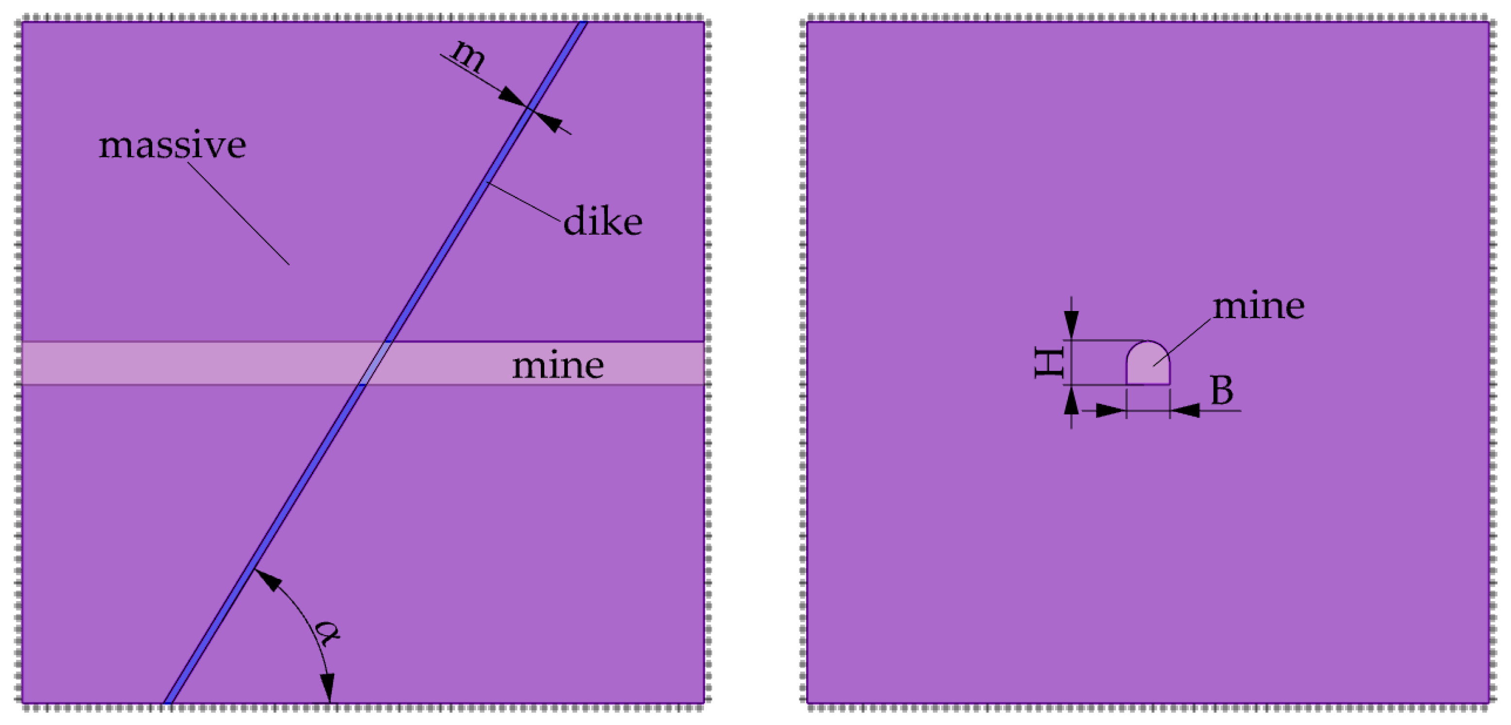
A numerical modeling approach was employed to predict the spatial dimensions of brittle failure zones in three-dimensional space. The initial stress state was defined using a stress field where the minimum principal stress (σ3) aligned with the vertical direction, the intermediate principal stress (σ2) was oriented along the excavation axis, and the maximum principal stress (σ1) acted perpendicular to this axis. Boundary conditions for the numerical model were constrained by restricting displacements along all domain edges. C3D10 elements were utilized for meshing, and the finite element method (FEM) was applied to assess the influence of the dyke on the stability of the non-conforming rock face. The model dimensions were selected to eliminate boundary effects on the studied parameters. The excavation cross-section measured 5.1 m × 5.1 m, traversing the rock mass and intersecting the dyke (Figure 2). The dip angle of the dyke ranged from 150 to 900, while its thickness varied from 0.05 B to 1 B (where B is the excavation width).
The stress–strain state was simulated in two stages:
  • Initial stress initialization: The in situ stress field was applied to the undisturbed rock mass.
  • Excavation simulation: Sequential removal of elements corresponding to the advancing excavation.
The dyke–rock mass interface was modeled as a hard contact to replicate lithological bonding conditions.

3. Results

The results obtained a set of data on the formation of the brittle fracture zone both in the rock mass and in the zone of dyke influence. The relative size of the brittle fracture zone in the instrumental experiments was understood as the ratio between the actual height of the excavation and the design height. The relative stress state indicator is understood as the ratio between the actual stress and the uniaxial compression strength of the rock. A characteristic feature of brittle fracture zones was the formation of a V-shaped arch in the roof of the excavation.
Analyzing the data of the surveyor’s surveys, one can notice that the values in different parts of the space vary quite widely. This is due to the fact that the considered sample is oriented differently with respect to the stress–strain state of the mass, as well as the geological conditions, which is typical for the conditions of Khibiny deposits.
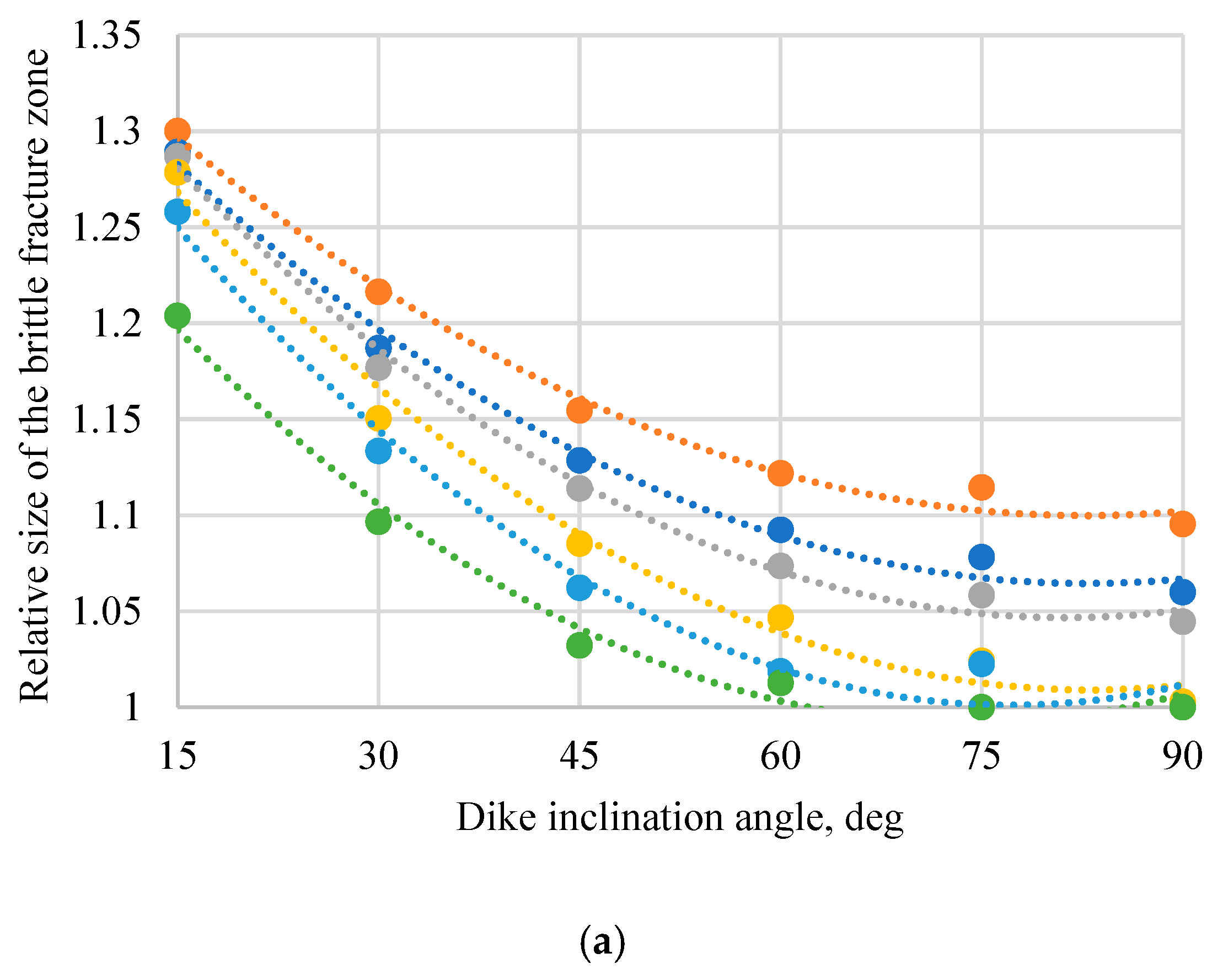
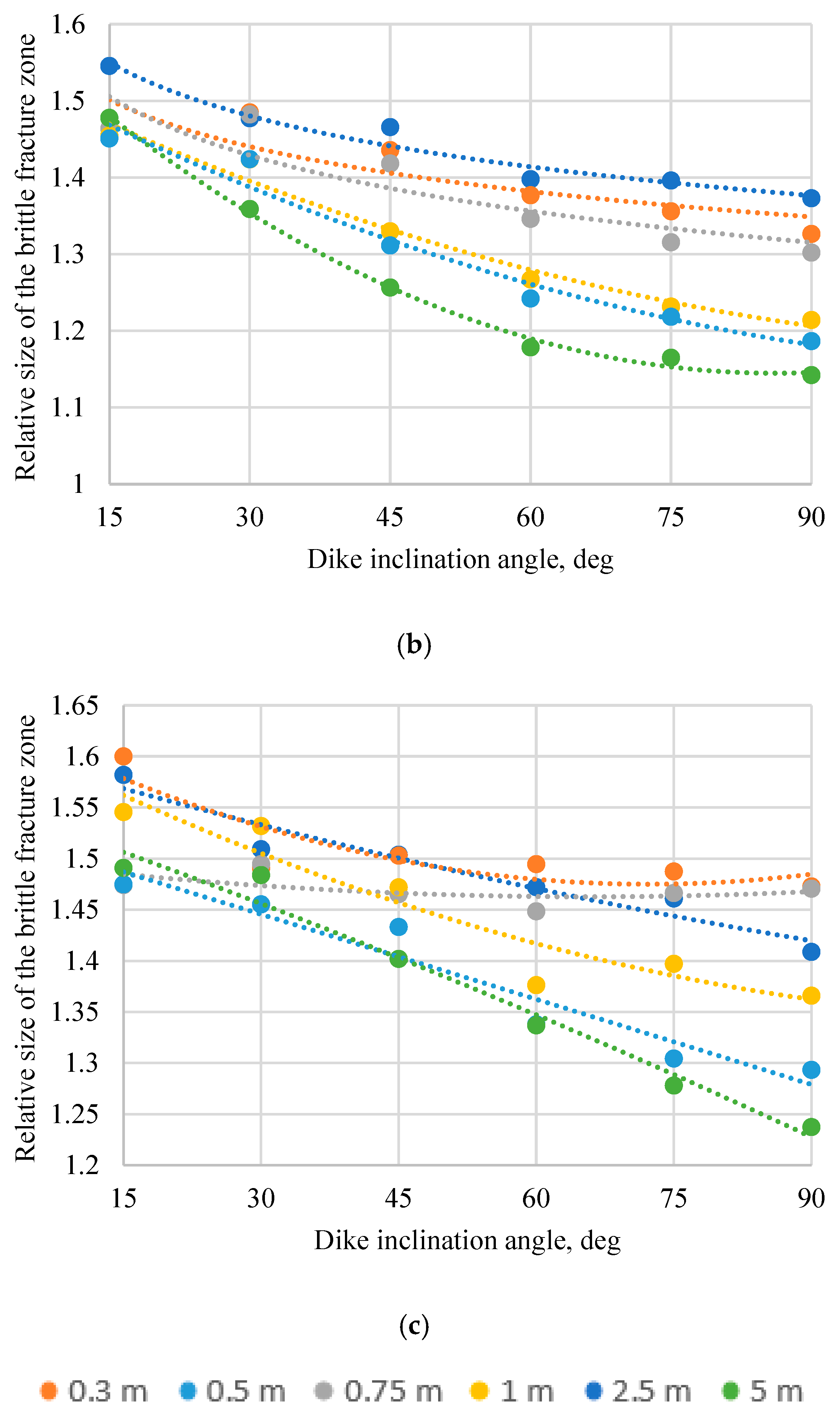
The numerical model, incorporating a custom program into commercial software, evaluates brittle failure zone dimensions by varying the cohesion and friction angles as deformations progress. The results of numerical modeling of the size of the brittle fracture zone as a function of the initial stress state are shown in Figure 4.
Figure 4 illustrates the variation in the brittle failure zone size depending on the initial stress field, dyke thickness, and dip angle. The coefficient of determination (R2) was found to range between 0.75 and 0.97, indicating the quality of the model’s predictive capability for estimating brittle failure zone dimensions under varying geomechanical conditions. All plots demonstrate that an increase in the horizontal stress component leads to expansion of the brittle failure zone within the dyke, with the most significant changes occurring between stress ratios of 2:1.5:1 and 3:1:1. The size of the brittle failure zone within the dykes (Figure 4) was found to exhibit a pronounced dependence on their geometric parameters and initial stress state. For thin dykes (0.3 m thickness) with a dip angle of 15° under a stress ratio of 4:2:1, the relative failure zone size reached 1.72. In contrast, an increase in dyke thickness to 5.0 m reduced this parameter to 1.11. An angular dependence was also observed: the failure zone decreased by 20–25% as the dip angle increased to 90°, a phenomenon attributed to the homogenization of stress distribution near the subvertical geological structures.
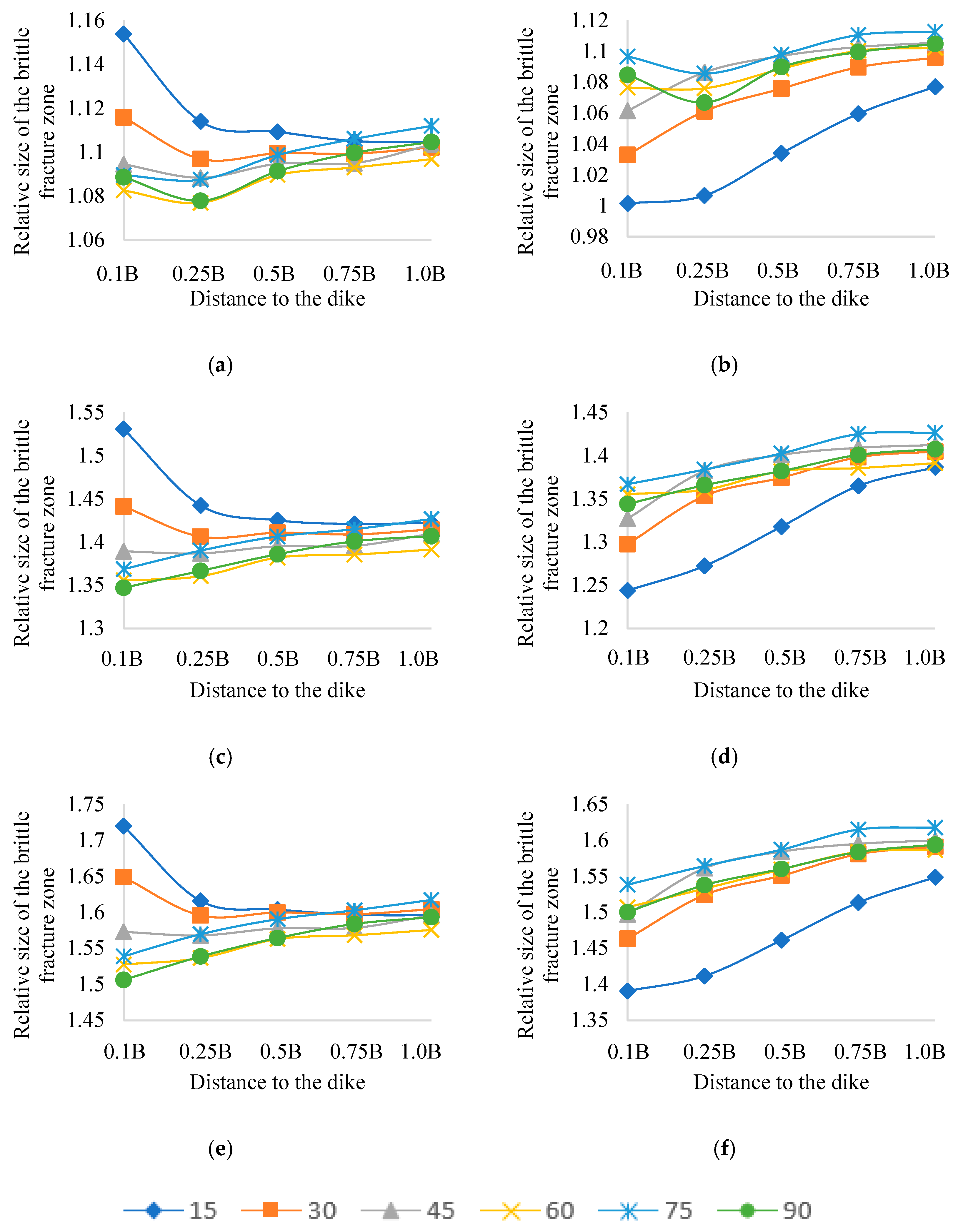
The host rock mass within the dyke’s influence zone (Figure 5, Table 2, Table 3 and Table 4) is characterized by asymmetric development of failure zones, attributed to the redistribution of tectonic stresses. At a dip angle of 15°, the failure zone in the hanging wall exceeds that in the footwall by a factor of 1.35. However, increasing the dip angle to 90° eliminates the asymmetry, equalizing the ratio to 1.0.
An increase in dyke thickness from 0.3 m to 2.5 m reduces the failure zone in the hanging wall by 18–25%, a phenomenon explained by stress redistribution within the stiffer intrusive body. Expansion of the horizontal stress component ratio from 2:1.5:1 to 4:2:1 results in a 44–60% enlargement of the failure zone. Growth cessation occurs at the critical threshold (σ/σc > 0.8), identified in Figure 3, due to the attainment of the rock mass’s ultimate equilibrium state.
The results of predicting brittle fracture zones using the modified Mohr–Coulomb model, accounting for rock weakening, showed good agreement between field observations and numerical experiments.

4. Conclusions

This study investigated the brittle failure zones of mine workings influenced by dykes composed of stronger rocks within tectonically stressed rock masses. Numerical modeling accounted for rock strength degradation but excluded hydrogeological, thermal, and operational factors. The evaluation considered dykes of varying geometries, stress states, thicknesses, and dip angles. The results demonstrated that shallow-dipping dykes (angles below 30°) generate the largest brittle failure zones within the dyke and hanging wall due to localized stress concentrations from stress redistribution. Minimal failure was observed in the footwall, where stresses are redistributed into the stiffer dyke.
The formation of brittle failure zones near dykes depends on the interplay of dyke geometry, mechanical properties, and initial stress conditions. Thin dykes (<0.5 m) with dip angles below 30° and dominant horizontal stresses exhibited maximum failure zones (up to 1.72). The host rock showed significant failure asymmetry (30–35% for thin dykes at 15° dip), requiring tailored stabilization strategies. Increasing horizontal stress ratios (2:1.5:1 to 4:2:1) caused nonlinear failure zone expansion (44–60%), with growth ceasing at critical stress thresholds (σ/σc > 0.8, Figure 3), marking the rock mass’s equilibrium. Asymmetric stress distributions at dyke–rock contacts, driven by mechanical contrasts, were identified as destabilizing factors.
The derived correlations for assessing stability in dyke-affected zones provide critical insights. The numerical model enhanced prediction reliability and serves as a foundation for designing support systems in horizontal workings. Dyke geometry (thickness, dip angle) and initial stress state influenced the failure zone size by up to 30% and 60%, respectively, necessitating their integration into support system design.
Key recommendations include minimizing intersection angles with dykes to above 60°, implementing reinforced supports in high-stress regimes (σ123 = 4:2:1), and adopting stress-relief measures. A classification system was proposed:
Category A (failure zone ≤ 1.15, asymmetry < 5%) applies to thick dykes (>2.5 m) intersected at angles > 60° under stress ratios of 2:1.5:1.
Category B (failure zone > 1.7, asymmetry 30–35%) corresponds to thin dykes (<0.5 m) with angles < 30° and stress ratios of 4:2:1.
This study highlights the need to account for dyke orientation and thickness in stability assessments. Limitations include the exclusion of hydrogeological and thermal factors, which should be addressed in future research to refine predictive models.

Author Contributions

Conceptualization, P.A.D. and P.B.; methodology, P.B.; validation, P.A.D.; formal analysis, P.A.D.; investigation, P.B.; resources, P.B.; data curation, P.B.; writing—original draft preparation, P.B.; writing—review and editing, P.A.D.; visualization, P.B.; supervision, P.A.D.; project administration, P.A.D. All authors have read and agreed to the published version of the manuscript.

Funding

This research received no external funding.

Institutional Review Board Statement

Not applicable.

Informed Consent Statement

Informed consent was obtained from all subjects involved in the study. Written informed consent has been obtained from the patients to publish this paper.

Data Availability Statement

Data are contained within the article.

Conflicts of Interest

The authors declare no conflicts of interest.

References

  1. Zhang, J.; Kuang, M.; Zhang, Y.; Feng, T. Evaluation and analysis of the causes of a landslide and treatment measures during the excavation of a tunnel through a soil-rock interface. Eng. Fail. Anal. 2021, 130, 105784. [Google Scholar] [CrossRef]
  2. Do, N.A.; Dias, D.; Dinh, V.D.; Tran, T.T.; Dao, V.C.; Dao, V.D.; Nguyen, P.N. Behavior of noncircular tunnels excavated in stratified rock masses—Case of underground coal mines. J. Rock Mech. Geotech. Eng. 2019, 11, 99–110. [Google Scholar] [CrossRef]
  3. Yin, X.; Zhang, A.; Zhang, X. A Review of the Influence of Microscopic Characteristics on the Progressively Brittle Failure of Foliated Rocks Subjected to Compression Loading. Geotech. Geol. Eng. 2022, 40, 1663–1673. [Google Scholar] [CrossRef]
  4. Belyakov, N.A.; Emelyanov, I.A. Inclusion of rock mass fracturing in determination of in situ stress state by overcoring using multi-component displacement sensor. MIAB Min. Inf. Anal. Bull. 2024, 145–164. (In Russian) [Google Scholar] [CrossRef]
  5. Besimbayeva, O.G.; Khmyrova, E.N.; Tutanova, M.S.; Flindt, N.; Sharafutdinov, R.R. Modern data analysis technologies used for geomechanical monitoring. Review. Kompleks. Ispolz. Miner. Syra = Complex Use Miner. Resour. 2023, 326, 5–15. [Google Scholar] [CrossRef]
  6. Falmagne, V.; Doucet, C.; Yergeau, D.; St-Onge, N.; Durham, C.; Jacobs, R.; Pyy, A.; Heller, A. Seismic response of large-scale to medium-scale geological structures in deep mines. Deep Mining 2024. In Proceedings of the 10th International Conference on Deep and High Stress Mining, Australian Centre for Geomechanics, Perth, Australia, 24–26 September 2024; Andrieux, P., Cumming-Potvin, D., Eds.; pp. 153–170. [Google Scholar] [CrossRef]
  7. Thiele, S.T.; Cruden, A.R.; Micklethwaite, S. Failure of load-bearing dyke networks as a trigger for volcanic edifice collapse. Commun. Earth Environ. 2023, 4, 382. [Google Scholar] [CrossRef]
  8. Thiele, S.T.; Cruden, A.R.; Zhang, X.; Micklethwaite, S.; Matchan, E.L. Reactivation of Magma Pathways: Insights from Field Observations, Geochronology, Geomechanical Tests, and Numerical Models. J. Geophys. Res. Solid Earth 2021, 126, e2020JB021477. [Google Scholar] [CrossRef]
  9. Bakhtavar, E.; Abdollahisharif, J.; Mohammadi, D. Analysis and improvement of blasting operation in porphyry, diorite dyke, and trachyte Sungun zones: In-situ investigations. Int. J. Min. Geo-Eng. 2022, 56, 19–24. [Google Scholar] [CrossRef]
  10. Gay, N.C. In-situ stress measurements in Southern Africa. Tectonophysics 1975, 29, 447–459. [Google Scholar] [CrossRef]
  11. Sudhishna, P.N.R.L.; Mondal, S.; Mondal, T.K.; Das, G. Study of restricted fractures in veins and dykes, and associated stress distribution. J. Earth Syst. Sci. 2024, 133, 31. [Google Scholar] [CrossRef]
  12. Alekseev, A. Face deformation in tunneling in the zone of structural and mechanical heterogeneity. Min. Inf. Anal. Bull. 2018, 12, 48–56. [Google Scholar] [CrossRef]
  13. Basalaeva, P.; Kuranov, A.D. Influence of dip angle of lithologically nonuniform interburden on horizontal mine opening stability during driving. MIAB Min. Inf. Anal. Bull. 2024, 3, 17–30. (In Russian) [Google Scholar] [CrossRef]
  14. Pospehov, G.B.; Norova, L.P.; Izotova, V.A. Comparing the methods of grain size analysis of gypsum-containing sulfuric acid wastes neutralized with limestone. Sustain. Dev. Mt. Territ. 2024, 16, 1729–1742. (In Russian) [Google Scholar] [CrossRef]
  15. Belikov, A.A.; Beliakov, N.A. Method of numerical modeling of rheological processes on the contour of single mine working. MIAB Min. Inf. Anal. Bull. 2024, 1, 94–108. [Google Scholar] [CrossRef]
  16. Yang, L.; Sharafisafa, M.; Shen, L. On the fracture mechanism of rock-like materials with interbedded hard-soft layers under Brazilian tests. Theor. Appl. Fract. Mech. 2021, 116, 103102. [Google Scholar] [CrossRef]
  17. Wang, J.; Deng, X.; Cao, W. Numerical Analysis on the Stability of Layered Surrounding Rock Tunnel Under the Conditions of Different Inclination Angle and Thickness. Am. J. Traffic Transp. Eng. 2019, 4, 67–74. [Google Scholar] [CrossRef]
  18. Sun, X.; Chen, F.; Miao, C.; Song, P.; Li, G.; Zhao, C.; Xia, X. Physical modeling of deformation failure mechanism of surrounding rocks for the deep-buried tunnel in soft rock strata during the excavation. Tunn. Undergr. Space Technol. 2018, 74, 247–261. [Google Scholar] [CrossRef]
  19. Rong, P.; Zuo, Y.; Lin, J.; Chen, Q.; Zheng, L.; Jin, K. Study of mechanical properties and failure characteristics of combined rock mass with weak interlayer. Géoméch. Geophys. Geo-Energy Geo-Resour. 2022, 8, 89. [Google Scholar] [CrossRef]
  20. Nunes, M.; Meguid, M. A study on the effects of overlying soil strata on the stresses developing in a tunnel lining. Tunn. Undergr. Space Technol. 2009, 24, 716–722. [Google Scholar] [CrossRef]
  21. Protosenya, A.G.; Veselova, A.V.; Kotikov, D.A. Assessment of stress concentration in neighborhood of karst voids during ore mining. MIAB Min. Inf. Anal. Bull. 2024, 2, 5–22. (In Russian) [Google Scholar] [CrossRef]
  22. Zhang, D.-M.; Huang, H.-W.; Hu, Q.-F.; Jiang, F. Influence of multi-layered soil formation on shield tunnel lining behavior. Tunn. Undergr. Space Technol. 2015, 47, 123–135. [Google Scholar] [CrossRef]
  23. Karasev, M.A.; Petrushin, V.V. Methodological issues in determination of initial parameters for modeling deformation of rock salt as a polycrystalline discrete medium. MIAB Min. Inf. Anal. Bull. 2024, 9, 47–64. [Google Scholar] [CrossRef]
  24. Kozyrev, A.A.; Enyutin, A.N.; Maltsev, V.A.; Semenova, I.E. Procedure for regional prediction of rockburst hazard and rock mass behavior, and for selection of technical solutions towards safe and efficient mining. In Innovatsionnyy Potentsial Kol’skoy Nauki [The Innovative Potential of the Kola Science]; Izd-vo KNTS RAN: Apatity, Russia, 2005; pp. 52–56. [Google Scholar]
  25. Trushko, V.L.; Baeva, E.K.; Blinov, A.A. Experimental Investigation on the Mechanical Properties of the Frozen Rocks at the Yamal Peninsula, Russian Arctic. Eng 2025, 6, 76. [Google Scholar] [CrossRef]
  26. Wawersik, W.; Fairhurst, C. A study of brittle rock fracture in laboratory compression experiments. Int. J. Rock Mech. Min. Sci. Géoméch. Abstr. 1970, 7, 561–575. [Google Scholar] [CrossRef]
  27. Kota, V.K.; Juneja, A.; Bajpai, R.K.; Srivastava, P. Stability Assessment of Cross-Tunnels in Jointed Rock Using Discrete Element Method. In Proceedings of the Indian Geotechnical Conference, Surat, India, 19–21 December 2019; Lecture Notes in Civil Engineering. Patel, S., Solanki, C.H., Reddy, K.R., Shukla, S.K., Eds.; Springer: Singapore, 2021; Volume 137. [Google Scholar] [CrossRef]
  28. Griffith, A.A. VI. The phenomena of rupture and flow in solids. Philos. Trans. R. Soc. Lond. Ser. A Contain. Pap. A Math. Or Phys. Character 1921, 221, 582–593. [Google Scholar]
  29. Irwin, G.R. Analysis of Stresses and Strains Near the End of a Crack Traversing a Plate. J. Appl. Mech. 1957, 24, 361–364. [Google Scholar] [CrossRef]
  30. Hoek, E.; Brown, E.T. The Hoek–Brown failure criterion and GSI–2018 edition. J. Rock Mech. Geotech. Eng. 2019, 11, 445–463. [Google Scholar] [CrossRef]
  31. Hoek, E.; Carranza-Torres, C.; Corkum, B. Hoek-Brown failure criterion—2002 edition. In Proceedings of the Fifth North American Rock Mechanics Symposium, Toronto, ON, Canada, 7–10 July 2002; Volume 1, pp. 267–273. [Google Scholar]
  32. Verbilo, P.E.; Iovlev, G.A.; Belyakov, N.A. Parameter selection for the Hoek–Brown model with softening of rock mass based on laboratory experiments on rock samples and discrete numerical simulations of jointed rock mass. MIAB Min. Inf. Anal. Bull. 2025, 2, 57–77. (In Russian) [Google Scholar] [CrossRef]
  33. Suresh, S. Fatigue of Materials, 2nd ed.; Cambridge University Press: Cambridge, UK, 1998. [Google Scholar] [CrossRef]
  34. Anderson, T.L.; Anderson, T.L. Fracture Mechanics: Fundamentals and Applications; CRC Press: Boca Raton, FL, USA, 2005. [Google Scholar]
  35. Lisjak, A.; Liu, Q.; Zhao, Q.; Mahabadi, O.K.; Grasselli, G. Numerical simulation of acoustic emission in brittle rocks by two-dimensional finite-discrete element analysis. Geophys. J. Int. 2013, 195, 423–443. [Google Scholar] [CrossRef]
  36. Trushko, V.L.; Rozanov, A.O.; Saitgaleev, M.M.; Petrov, D.N.; Ilinov, M.D.; Karmanskii, D.A.; Selikhov, A.A. Acoustic emission criteria for analyzing the process of rock destruction and evaluating the formation of fractured reservoirs at great depths. J. Min. Inst. 2024, 269, 848–858, EDN EGOJFL. [Google Scholar]
  37. Bieniawski, Z. Determining rock mass deformability: Experience from case histories. Int. J. Rock Mech. Min. Sci. Géoméch. Abstr. 1978, 15, 237–247. [Google Scholar] [CrossRef]
  38. Zhang, J.; Yu, Q.; Li, Y.; Pan, Z.; Liu, B. Hydraulic Fracture Vertical Propagation Mechanism in Interlayered Brittle Shale Formations: An Experimental Investigation. Rock Mech. Rock Eng. 2023, 56, 199–220. [Google Scholar] [CrossRef]
  39. Joughin, W. Managing geotechnical uncertainty and risk in mining. J. S. Afr. Inst. Min. Met. 2023, 123, 435–444. [Google Scholar] [CrossRef]
  40. Karasev, M.; Astapenka, T. Assessment of the Influence of Formation Conditions of Embankments and Spoil Heaps on Their Stability When Dumped on Clay-Salt Slurries. Eng 2025, 6, 2. [Google Scholar] [CrossRef]
  41. Garashchenko, Z.; Teremetskaya, V.; Gabov, V. Mining of coal pillars using unified excavation modules with local faces. Min. Ind. J. (Gorn. Promishlennost) 2024, 5S, 151–157. (In Russian) [Google Scholar] [CrossRef]
  42. Bažant, Z.P.; Zi, G. Microplane constitutive model for porous isotropic rocks. Int. J. Numer. Anal. Methods Géoméch. 2002, 27, 25–47. [Google Scholar] [CrossRef]
  43. Loseva, E.; Lozovsky, I.; Zhostkov, R. Refining Low Strain Pile Integrity Testing for Minor Flaw Detection with Complex Wavelet Transform. Civ. Eng. J. 2024, 10, 3194–3207. [Google Scholar] [CrossRef]
  44. Protosenya, A.G.; Kumov, V.V. Effect of soil body structure of mixed-type tunnel face on shape and size of subsidence trough on ground surface. Min. Informational Anal. Bull. 2024, 4, 5–21. (In Russian) [Google Scholar] [CrossRef]
  45. Chen, J.; Gu, S.; Zhou, X. The effects of weak interlayers on the dynamic mechanical properties and failure behaviours of rocks: A combined numerical and experimental analysis. Int. J. Impact Eng. 2023, 180, 104680. [Google Scholar] [CrossRef]
  46. Collins, I. A systematic procedure for constructing critical state models in three dimensions. Int. J. Solids Struct. 2003, 40, 4379–4397. [Google Scholar] [CrossRef]
  47. Vermeer, P.A.; De Borst, R. Non-Associated Plasticity for Soils, Concrete and Rock. In Physics of Dry Granular Media; NATO ASI Series; Herrmann, H.J., Hovi, J.P., Luding, S., Eds.; Springer: Dordrecht, The Netherlands, 1998; Volume 350, pp. 163–196. [Google Scholar]
  48. Cai, M.; Kaiser, P.; Tasaka, Y.; Minami, M. Determination of residual strength parameters of jointed rock masses using the GSI system. Int. J. Rock Mech. Min. Sci. 2007, 44, 247–265. [Google Scholar] [CrossRef]
  49. Alejano, L.; Alonso, E.; Rodríguez-Dono, A.; Fernández-Manín, G. Application of the convergence-confinement method to tunnels in rock masses exhibiting Hoek–Brown strain-softening behaviour. Int. J. Rock Mech. Min. Sci. 2010, 47, 150–160. [Google Scholar] [CrossRef]
  50. Hajiabdolmajid, V.; Kaiser, P.; Martin, C. Modelling brittle failure of rock. Int. J. Rock Mech. Min. Sci. 2002, 39, 731–741. [Google Scholar] [CrossRef]
  51. Liu, Y.; Tang, D.; Xu, H.; Zhao, T.; Hou, W. Effect of interlayer mechanical properties on initiation and propagation of hydraulic fracturing in laminated coal reservoirs. J. Pet. Sci. Eng. 2022, 208, 109381. [Google Scholar] [CrossRef]
  52. Cai, W.; Deng, J.; Feng, Y.; Lin, H.; Tanko, M.O.; Ma, C. Developing a geomechanics-modeling based method for lost circulation risk assessment: A case study in Bohai Bay, China. J. Pet. Sci. Eng. 2022, 210, 110045. [Google Scholar] [CrossRef]
  53. Huang, Y.; Yin, X.; Yan, E.-C.; Li, Y.; Song, K. Brittle Failure Modes and Mechanisms in Foliated Rock Under Uniaxial Compression: Laboratory Testing and Particle Flow Modeling. Geotech. Geol. Eng. 2024, 42, 2861–2880. [Google Scholar] [CrossRef]
  54. Zhao, H.; Deng, B.; Zhang, D.; Li, M.; Song, Z. Influence of weak interlayer thickness on mechanical response and failure behavior of rock under true triaxial stress condition. Eng. Fail. Anal. 2024, 162, 108419. [Google Scholar] [CrossRef]
  55. Cong, R.; Yang, R.; Li, G.; Huang, Z.; Gong, Y.; Jing, M.; Lu, M. Geomechanical Properties of Thinly Interbedded Rocks Based on Micro- and Macro-Scale Measurements. Rock Mech. Rock Eng. 2023, 56, 5657–5675. [Google Scholar] [CrossRef]
  56. Wang, H.; Zhao, W.; Sun, D.; Guo, B. Mohr-Coulomb Yield Criterion in Rock Plastic Mechanics. Chin. J. Geophys. 2012, 55, 733–741. [Google Scholar] [CrossRef]
  57. Gospodarikov, A.P.; Trofimov, A.V.; Kirkin, A.P. Evaluation of deformation characteristics of brittle rocks beyond the limit of strength in the mode of uniaxial servohydraulic loading. J. Min. Inst. 2022, 256, 539–548. [Google Scholar] [CrossRef]
  58. Korchak, P. Geomechanical prediction of growth of brittle fracture zones in the vicinity of underground excavations in over-stress rock mass. Min. Informational Anal. Bull. 2021, 5, 85–98. [Google Scholar] [CrossRef]
  59. Renani, H.R.; Martin, C.D. Cohesion degradation and friction mobilization in brittle failure of rocks. Int. J. Rock Mech. Min. Sci. 2018, 106, 1–13. [Google Scholar] [CrossRef]
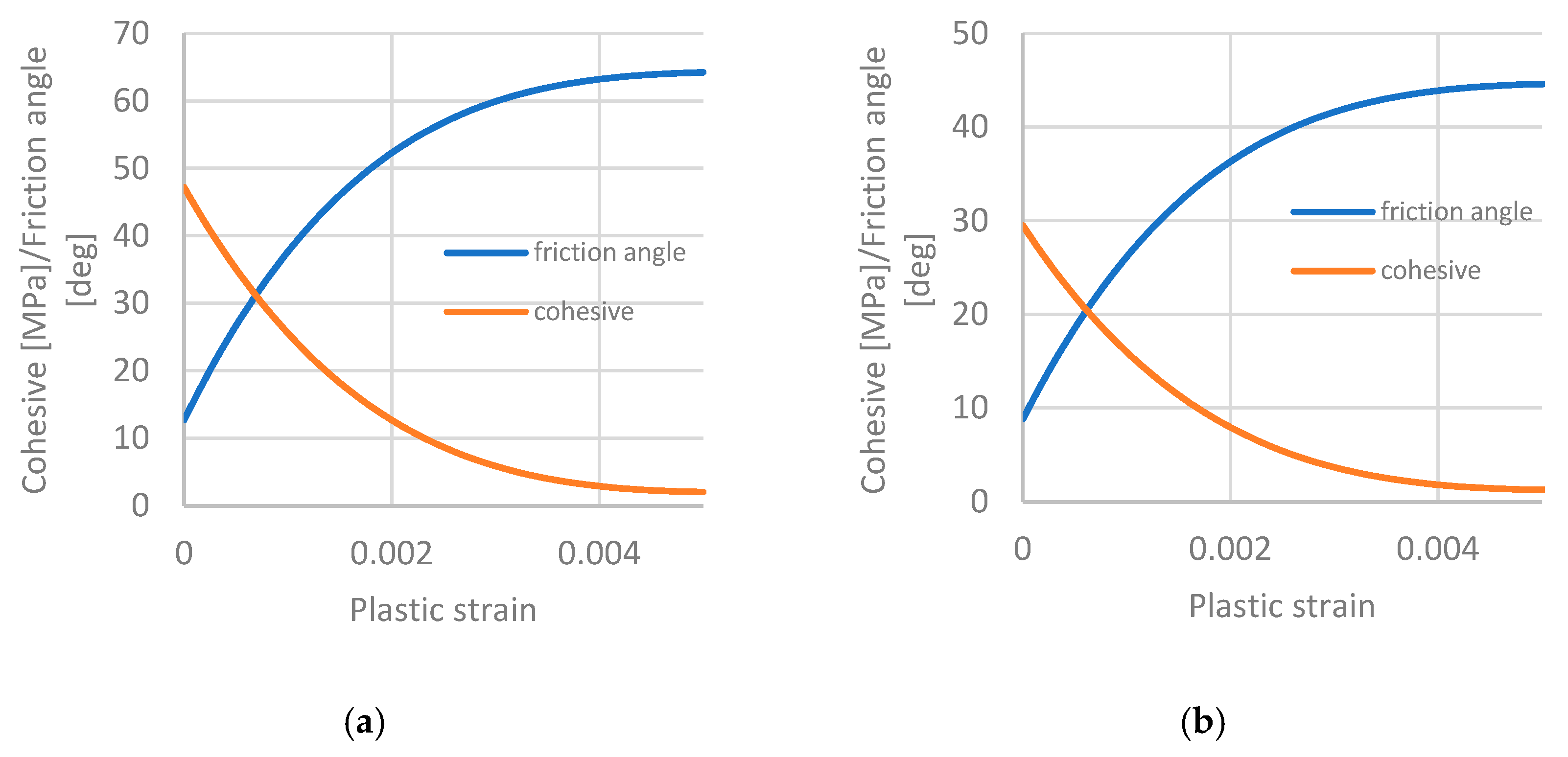
Figure 1. Diagram of the softening model parameters: (a) dykes; (b) rock mass.
Eng 06 00091 g001
Figure 2. Calculation diagram for excavations.
Eng 06 00091 g002
Figure 3. Graph of dependence of the size of brittle fracture zones on the stress state on the excavation contour.
Eng 06 00091 g003
Figure 4. Diagram of stress–strain state formation on the mine contour depending on the dyke thickness and its dip angle (in the dyke zone) at different types of stress state: (a) 2:1.5:1; (b) 3:1:1; (c) 4:2:1.
Eng 06 00091 g004aEng 06 00091 g004b
Figure 5. Relative size of the brittle fracture zone in the dyke influence zone at a dyke thickness of 0.3 m as a function of dyke inclination angle on the hanging side and on the recumbent side at a stress state of 2:1.5:1 (a,b), 3:1:1 (c,d), 4:2:1 (e,f).
Eng 06 00091 g005
Table 1. Parameters of the deformation model.
Rock ParameterUnitMassiveDyke
Modulus of deformation of rock, EGPa1070
Poisson’s ratio, υ-0.230.23
Compressive strength, σMpa120300
Initial cohesion, ciMpa29.547.2
Residual cohesion, crMpa1.22.06
Initial friction angle, φidegrees8.812.7
Residual friction angle, φrdegrees44.864.2
Table 2. Range of variation in the size of the brittle fracture zone under a stress ratio of 2:1.5:1.
Thickness of the Dyke
0.3 m0.5 m0.75 m1.0 m2.5 m5.0 m
0.1 B1.08–1.16/
1.00–1.085
1.07–1.165/
0.96
1.059–1.168/
0.95–1.06
1.11–1.24/
0.99–1.108
1.02–1.15/
0.91–1.02
1.00–1.11/
0.91–1.2
0.25 B1.06–1.11/
1.00–1.067
1.07–1.11/
0.99
1.06–1.109/
0.97–1.059
1.121–1.18/
1.03–1.123
1.028–1.109/
0.93–1.026
1.02–1.07/
0.93–1.015
0.5 B1.09–1.10/
1.03–1.09
1.07–1.10/
1.01–1.07
1.077–1.099/
1.002–1.076
1.147–1.17/
1.06–1.148
1.05–1.08/
0.97–1.05
1.043–1.057/
0.96–1.04
0.75 B1.10/
1.05–1.099
1.09–1.10/
1.03–1.09
1.088–1.097/
1.034–1.089
1.17/
1.099–1.159
1.066–1.079/
1.00–1.068
1.055–1.058/
0.99–1.059
1.0 B1.105–1.11/
1.077–1.11
1.10/
1.06–1.10
1.095–1.1/
1.049–1.1
1.17–1.176/
1.12–1.176
1.075–1.077/
1.02–1.08
1.053–1.068/
1.01–1.078
Table 3. Range of variation in the size of the brittle fracture zone under a stress ratio of 3:1:1.
Thickness of the Dyke
0.3 m0.5 m0.75 m1.0 m2.5 m5.0 m
0.1 B1.53–1.346/
1.24–1.344
1.52–1.54/
1.19–1.53
1.52–1.30/
1.17–1.30
1.52–1.31/
1.15–1.30
1.44–1.37/
1.10–1.43
1.37–1.20/
1.08–1.19
0.25 B1.44–1.366/
1.27–1.365
1.42–1.599/
1.24–1.592
1.41–1.34/
1.21–1.33
1.41–1.34/
1.21–1.33
1.36–1.48/
1.14–1.22
1.33–1.26/
1.13–1.25
0.5 B1.425–1.375/
1.32–1.369
1.39–1.63/
1.29–1.62
1.39–1.36/
1.26–1.36
1.39–1.36/
1.25–1.36
1.34–1.32/
1.19–1.31
1.31–1.30/
1.17–1.29
0.75 B1.42–1.38/
1.32–1.39
1.39–1.638/
1.32–1.65
1.39–1.38/
1.31–1.38
1.39–1.38/
1.30–1.38
1.34/
1.25–1.35
1.31–1.33/
1.23–1.33
1.0 B1.422–1.406/
1.386–1.407
1.39–1.65/
1.36–1.65
1.387–1.385/
1.33–1.384
1.39/
1.33–1.40
1.34–1.36/
1.27–1.37
1.31–1.34/
1.25–1.36
Table 4. Range of variation in the size of the brittle fracture zone under a stress ratio of 4:2:1.
Thickness of the Dyke
0.3 m0.5 m0.75 m1.0 m2.5 m5.0 m
0.1 B1.72–1.51/
1.39–1.50
1.82–1.54/
1.39–1.54
1.74–1.47/
1.27–1.46
1.79–1.49/
1.33–1.48
1.69–1.37/
1.20–1.37
1.59–1.34/
1.17–1.34
0.25 B1.61–1.54/
1.41–1.54
1.69–1.60/
1.46–1.59
1.60–1.51/
1.33–1.50
1.66–1.56/
1.39–1.56
1.55–1.43/
1.26–1.43
1.50–1.41/
1.23–1.40
0.5 B1.60–1.564/
1.46–1.56
1.66–1.63/
1.52–1.62
1.58–1.61/
1.39–1.61
1.65–1.62/
1.44–1.62
1.53–1.48/
1.32–1.47
1.48–1.46/
1.30–1.46
0.75 B1.59–1.58/
1.51–1.58
1.66–1.64/
1.56–1.65
1.57–1.65/
1.46–1.64
1.64–1.66/
1.51–1.64
1.53–1.51/
1.40–1.51
1.48–1.49/
1.37–1.49
1.0 B1.59/
1.55–1.59
1.66–1.65/
1.61–1.65
1.57–1.67/
1.49–1.67
1.64–1.67/
1.56–1.67
1.52–1.54/
1.42–1.55
1.48–1.52/
1.40–1.52
Disclaimer/Publisher’s Note: The statements, opinions and data contained in all publications are solely those of the individual author(s) and contributor(s) and not of MDPI and/or the editor(s). MDPI and/or the editor(s) disclaim responsibility for any injury to people or property resulting from any ideas, methods, instructions or products referred to in the content.