Article

Intensification of Thermal Performance of a Heat Exchanger Tube with Knitted Wire Coil Turbulators Installed

1
School of Industrial and Engineering Technology, Mahanakorn University of Technology, Bangkok 10530, Thailand
2
Engineering Innovation Unit, Graduate School of Regional Innovation Studies, Mie University, Tsu 514-8507, Mie, Japan
3
Department of Mechanical Engineering, Faculty of Engineering, Mie University, Tsu 514-8507, Mie, Japan
4
Department of Mechanical Engineering, Faculty of Engineering, Aichi Institute of Technology, Toyota 470-0392, Aichi, Japan
5
School of Engineering, King Mongkut’s Institute of Technology Ladkrabang, Bangkok 10530, Thailand
6
Heat Pipe and Thermal Tool Design Research Unit (HTDR), Faculty of Engineering, Mahasarakham University, Maha Sarakham 44150, Thailand
*
Author to whom correspondence should be addressed.
Eng 2025, 6(12), 337; https://doi.org/10.3390/eng6120337
Submission received: 13 September 2025 / Revised: 10 November 2025 / Accepted: 19 November 2025 / Published: 26 November 2025
(This article belongs to the Section Chemical, Civil and Environmental Engineering)

Abstract

This study reports on heat transfer augmentation by knitted wire coil turbulators in a fully developed turbulent regime. Four knitted wire coil turbulators with different wire loop number densities (N = 6, 8, 10, and 12 loops per pitch, with 1.0 pitch = 6.8 mm) were tested. Each was made by winding a 0.7 mm copper wire around a 1.0 mm core rod. Experiments were conducted under a constant 600 W/m2 wall heat flux. The flow behaviors observed through a dye injection technique revealed that the wire coil induced secondary flows and developed shear layers, contributing to enhanced heat transfer. Heat transfer improved with increasing wire loop number density. Application of knitted wire coil turbulators increased the Nusselt number (Nu) by 86, 95.4, 103.2, and 109.3% for N = 6, 8, 10, and 12, respectively. This corresponded to increased friction factors (f) by 1.77, 1.97, 2.15, and 2.31 times, respectively. The tube with coils having N = 12 yielded the highest thermal performance index (TPI), 1.4, at a Reynolds number of 5000. The empirical correlations for Nu, f, and TPI showed deviations within ±2.1, ±0.68, and ±2.28%, respectively.

1. Introduction

The increasing energy consumption in thermal processes involving heat exchanger applications necessitates a search for innovative heat transfer enhancements aimed at improving thermal performance. In response, new heat transfer augmentation technologies have been developed and widely implemented [1,2,3]. A key challenge in designing heat transfer enhancement devices for heat exchangers is to achieve a compact design that can handle high heat fluxes while minimizing pumping power. Among the most popular heat transfer enhancement (HTE) techniques are turbulent generators, which have been extensively studied and applied in industrial processes. Turbulators with diverse shapes and configurations have been developed for better HTE solutions. One of the promising HTE devices are wire meshes. They are effective due to their exceptionally large specific surface area in heat exchangers [3,4,5,6,7,8,9,10]. The key advantages of wire mesh/coils over other enhancement devices, such as fins or turbulators, are their lightweight and flexibility, allowing for easy integration into existing systems with no significant modifications. Additionally, wire mesh/coils offer a low pressure drop compared to other enhancement techniques, ensuring efficient heat transfer with minimal pumping power requirements.
Extensive investigations have been conducted since the early 20th century to analyze the thermohydraulic performance within tubes containing various wire-matrix turbulators, including wire coils, wire meshes, wire rods, and twisted wire brushes. Hong et al. [11] proposed the use of wire coils arranged in different configurations, including uniform pitch, varying pitches, and gradually varying widths. Their results revealed that wire coils with varying pitch and gradually varying widths achieved higher heat transfer and friction factors than those with uniform pitch. Among these, a wire coil with a gradually varying width exhibited the highest thermohydraulic performance factor, reaching 1.14. Eiamsa-ard et al. [12] fabricated tandem wire coil elements for use in a square duct for 4000 ≤ Re ≤ 25,000. In addition to a full-length coil, they analyzed 1.0D and 2.0D length coil elements installed in tandem with varying free-space lengths inside the duct. At a Re of 4000, the maximum enhancement factors of the full-length, 1.0D and 2.0D coils, were approximately 1.33, 1.25 and 1.24, respectively. Abdul Hamid et al. [13] investigated the combined effects of wire coil inserts and TiO2-SiO2 nanofluids on heat transfer enhancement and thermohydraulic performance. The nanofluid concentrations ranged from 0.5 to 3.0%, while the wire coil inserts were designed with pitch-to-diameter (P/D) ratios varying between 0.83 and 4.17. They found that the optimal thermohydraulic performance factor was achieved with a wire coil having a pitch ratio of 1.5 and a nanofluid containing 2.5% TiO2-SiO2 particles by volume. Dyga and Płaczek [14] reported that wire mesh packing significantly enhanced the heat transfer coefficient. Under the specific conditions of their research, the overall energy achieved using wire mesh packing reached approximately 40%. Xing et al. [15] applied a suspended mesh cylinder inside a tube. The suspended mesh directed fluid to the near-wall region, resulting in a larger velocity gradient near the tube surface. This greater velocity gradient significantly enhanced heat transfer, with augmentation reaching 1.84 in the transition flow regime. Liu et al. [16] examined the effects of sintered woven wire mesh on flow and heat transfer characteristics. A larger porosity resulted in higher permeability and a lower inertial coefficient. However, porosity had an insignificant impact on thermohydraulic behavior. Kurian et al. [17] compared the performance of stainless-steel wire mesh stacks with an in-house-made metal foam. Their results suggested that the wire mesh outperformed the metal foam, enhancing heat transfer by 28%, corresponding to a 2.25-fold improvement over the bare heat exchanger. Fu et al. [18] employed a sprayed wire mesh with varying porosities and wire diameters using an aluminum mesh created through a twin-wire thermal spraying system. The results suggested that the sprayed wire mesh achieved up to 77% of the ideal fin model performance, making it suitable for compact heat exchanger designs. Kotresha and Gnanasekaran [19] numerically investigated the performance of brass wire mesh porous media with porosities ranging from 0.77 to 0.85. Their findings indicated that the brass wire mesh enhanced heat transfer by up to twice that of a channel with no wire mesh. A wire mesh with a porosity of 0.85 outperformed those with porosities of 0.77 and 0.81 in heat transfer improvement, achieving 1.86- and 1.41-times higher performance, respectively. The mesh with a porosity of 0.85 demonstrated the best overall thermal performance among the tested porosities.
Sayed et al. [20] used three wire mesh modules featuring different mesh spacings in a liquid-to-air cross-flow. Heat transfer enhancements were observed for all wire mesh modules, with a volumetric heat transfer coefficient increase of up to 114% compared to the bare module. Nanan et al. [21] packed wire-rod bundles having different pitches and wire-rod counts per bundle in a round tube for heat transfer augmentation. Heat transfer increased with greater numbers of wire rods per bundle and smaller pitches, with enhancements reaching 69% for heat transfer and 353% for friction factors. Naphon and Suchana [22] applied twisted wire brushes of varying densities. They reported that increasing the density of full-length twisted wires enhanced heat transfer and Nusselt number, with the 300-wire insert giving the best results. Full-length inserts provided higher heat transfer than regularly spaced ones. Bhuiya et al. [23] reported that using a twisted wire brush enhanced heat transfer by up to 2.15 times, with thermohydraulic performance reaching a maximum value of 1.85, indicating a significant improvement in overall efficiency. Yu et al. [24] developed wire coils with different cross-sections (circular, equilateral, and square) for use in a twisted tube. The compound system enhanced the heat transfer rate by up to 45.9%. However, the overall thermal performance decreased due to a high friction factor, which increased by up to 675%. Dang and Wang [25] numerically assessed the performance of twined coils under laminar flow conditions. The twined coil induced secondary flow and fluid mixing, resulting in heat transfer and friction factor enhancements of 12–38 and 7.7–18 times, respectively. The thermal performance factor reached 2.16 at a Reynolds number of 1000. Keklikcioglu and Ozceyhan [26] employed convergent, convergent-divergent, and divergent conical wire coils in an ethylene glycol-water flow. Among the configurations, the divergent wire coil demonstrated the best thermal performance factor, as high as 1.62. Chompookham et al. [27] investigated the heat transfer characteristics of a heat exchanger equipped with a serrated wire coil at various coil diameter ratios and pitch ratios. They reported that heat transfer was augmented as the pitch ratio decreased and the coil diameter ratio rose. The pressure loss decreased as both the pitch and coil-diameter ratios increased. A serrated wire coil was found to increase the heat transfer and friction factor over plain tubes by up to 2.46 and 8.16 times, respectively, while the highest thermal performance was around 1.41 with a pitch ratio of 0.1969 and a diameter ratio of 0.94. Subirana et al. [28] examined the flow structure and heat transfer behaviors in a helical coil with varied pitch and blockage ratios in the laminar and transitional flow regimes. They found that the wire coil promoted continuous separation and reattachment of the boundary layer, disrupting the flow along the tube wall, thereby enhancing heat transfer. Hashemian et al. [29] used a multi-objective approach to examine the thermal performance of a helically coiled tube equipped with a helical wire. The results showed that the exergy efficiency inside the helical tube for single-phase flow was 87% greater than that of the helically coiled tube equipped with a helical wire. Hong et al. [30] investigated the heat transfer, friction factor, and thermal performance characteristics in a transverse corrugated tube equipped with twin/triple wire coils at various spacing ratios (S/D). Their findings indicated that the use of transverse corrugated tubes with wire coils significantly enhanced heat transfer, resulting in greater pressure losses compared to plain tubes. This was achieved by obtaining Nusselt number ratios of up to 2.6 and friction factor ratios of up to 21.3. The maximum thermal performance was approximately 1.09 for the traverse corrugated tube with twin wire coils at S/D = 18, whereas the performance for the traverse corrugated tube alone was about 1.26.
This review highlights various wire turbulators that enhance heat transfer performance, including mesh cylinders [15], sintered woven wire meshes [16], wire mesh heat exchangers [17], sprayed wire meshes [18], wire mesh blocks [19], wire-rod bundles [21], twisted wire brushes [22], twisted oval tubes [24], serrated wire coils [27], helically coiled pipes with helical wire inserts [29], and transverse corrugated tubes equipped with twin/triple wire coils [30] as depicted in Figure 1 and Table 1. This study specifically investigates a heat transfer tube equipped with knitted wire coil inserts. These inserts are flexible, allowing modifications to achieve an optimal balance between enhanced heat transfer and pressure drop, providing valuable insights into their design optimization and performance characteristics. An experimental investigation was conducted to evaluate the effects of wire loop densities (N = 6, 8, 10, and 12 loops per pitch, where 1.0 pitch = 6.8 mm, on heat transfer, pressure loss, thermal performance index (TPI), and flow behavior using dye techniques. The results from the tube with knitted wire coil inserts are compared to those with no inserts.
Figure 1. Various reported heat transfer enhancement devices. (a) Coiled wire [3]; (b) Conical spring [4]; (c) Triangle cross-sectioned coiled-wire [6]; (d) Wire-rod bundle [21]; (e) Wire coil [24]; (f) Convergent-divergent conical wire coils [26]; (g) Serrated wire coil [27]; (h) Corrugated tube fitted with wire coils [30].
Eng 06 00337 g001

2. Experimental Description

2.1. Knitted Wire Coil Turbulators

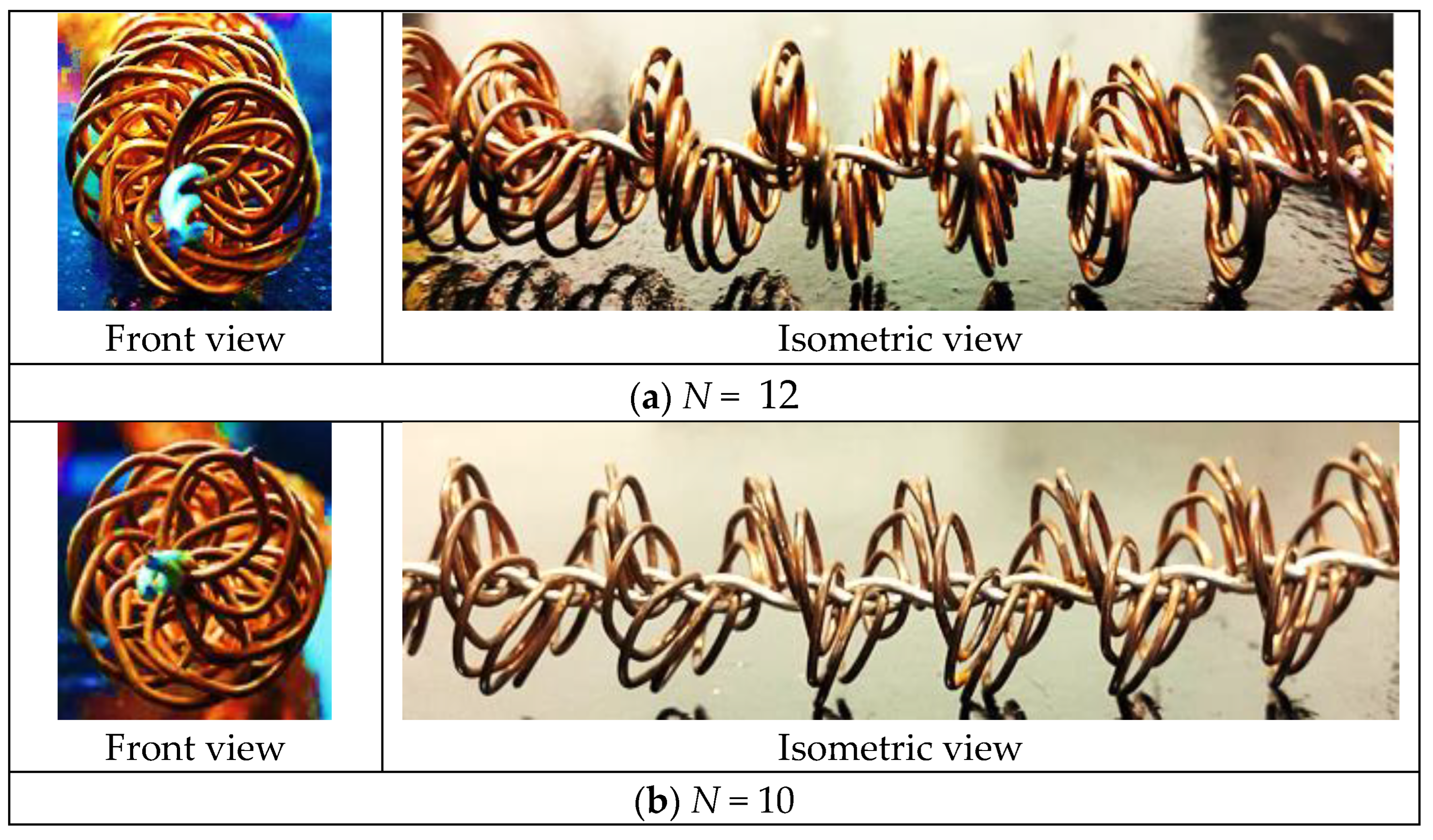
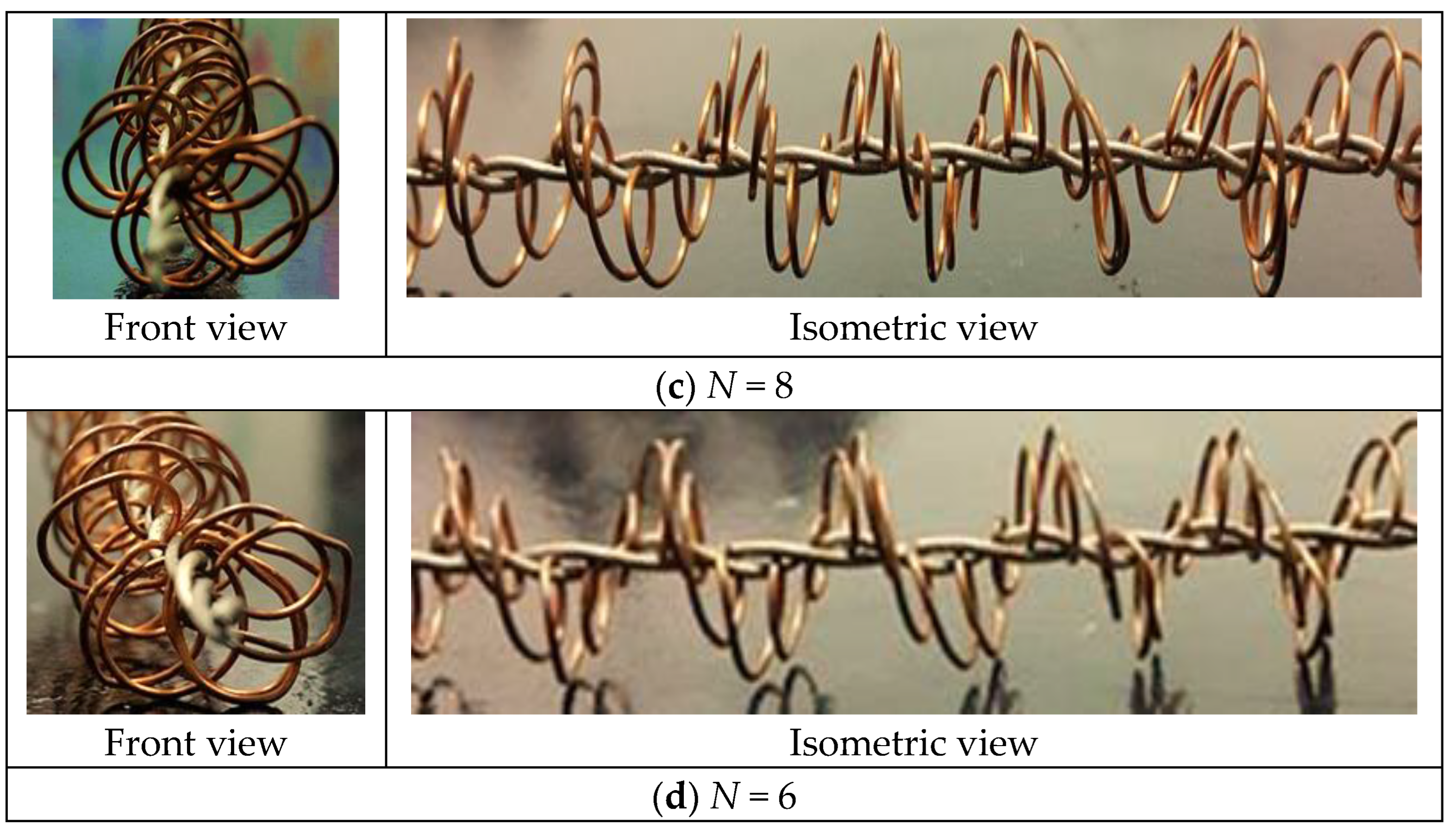
The knitted wire coil turbulators were made of 0.7 mm diameter copper wires wound around 1.0 mm diameter flexible core rods, as depicted in Figure 2 and Figure 3. Fabrication began by forming the copper wire into helical turns and inserting it into the gap between two twisted central core rods, shaping it into the desired looped or petal-like pattern. Prior to assembly, the wire positions were pre-marked using a circular template based on CAD design to guarantee uniform spacing and alignment. The wire loop density (N) was varied at 6, 8, 10, and 12 loops per pitch (1.0 pitch = 6.8 mm). For experimental analysis, the knitted wire coil turbulators were inserted into a 19 mm inner diameter heat exchanger tube, maintaining a constant 600 W/m2 wall heat flux.
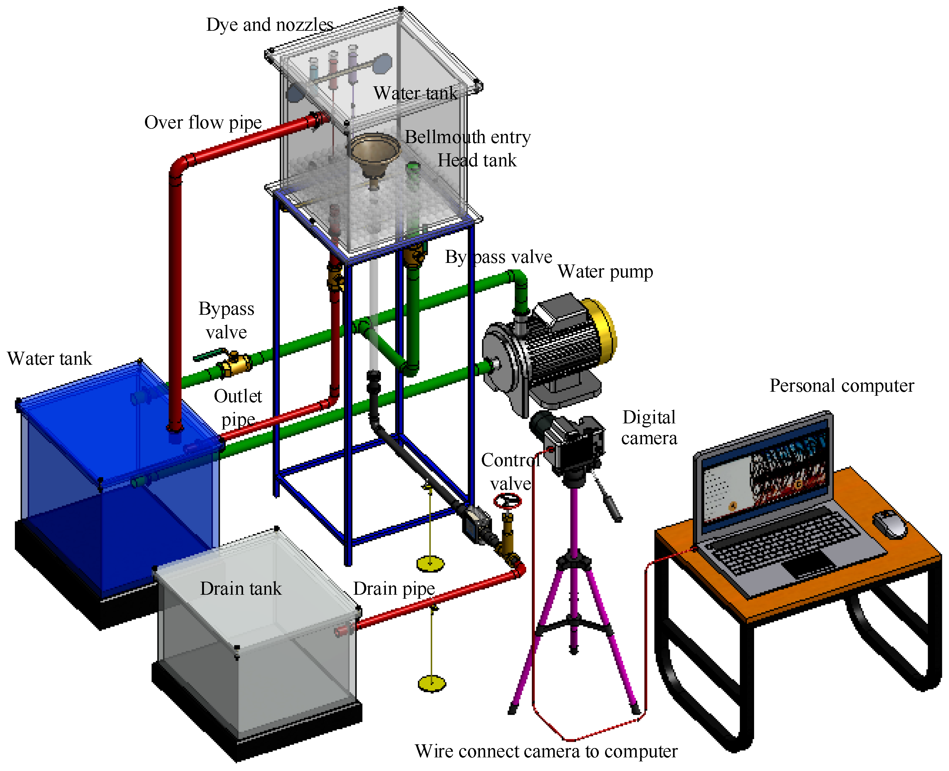
In the current experimental study, two methods of experimental setups were employed. Initially, the flow visualization in the laminar flow region of Reynolds number 1000, transition flow of Reynolds number 2500, and turbulent flow of Reynolds number 5000 is investigated using the dye visualization setup (Figure 4, Figure 5 and Figure 6). Secondly, the heat transfer test apparatus (Figure 7) is employed to investigate the heat transfer, friction factor and thermal performance index characteristics in the turbulent flow region with a Reynolds number between 5000 and 15,000.

2.2. Flow Visualization Setup

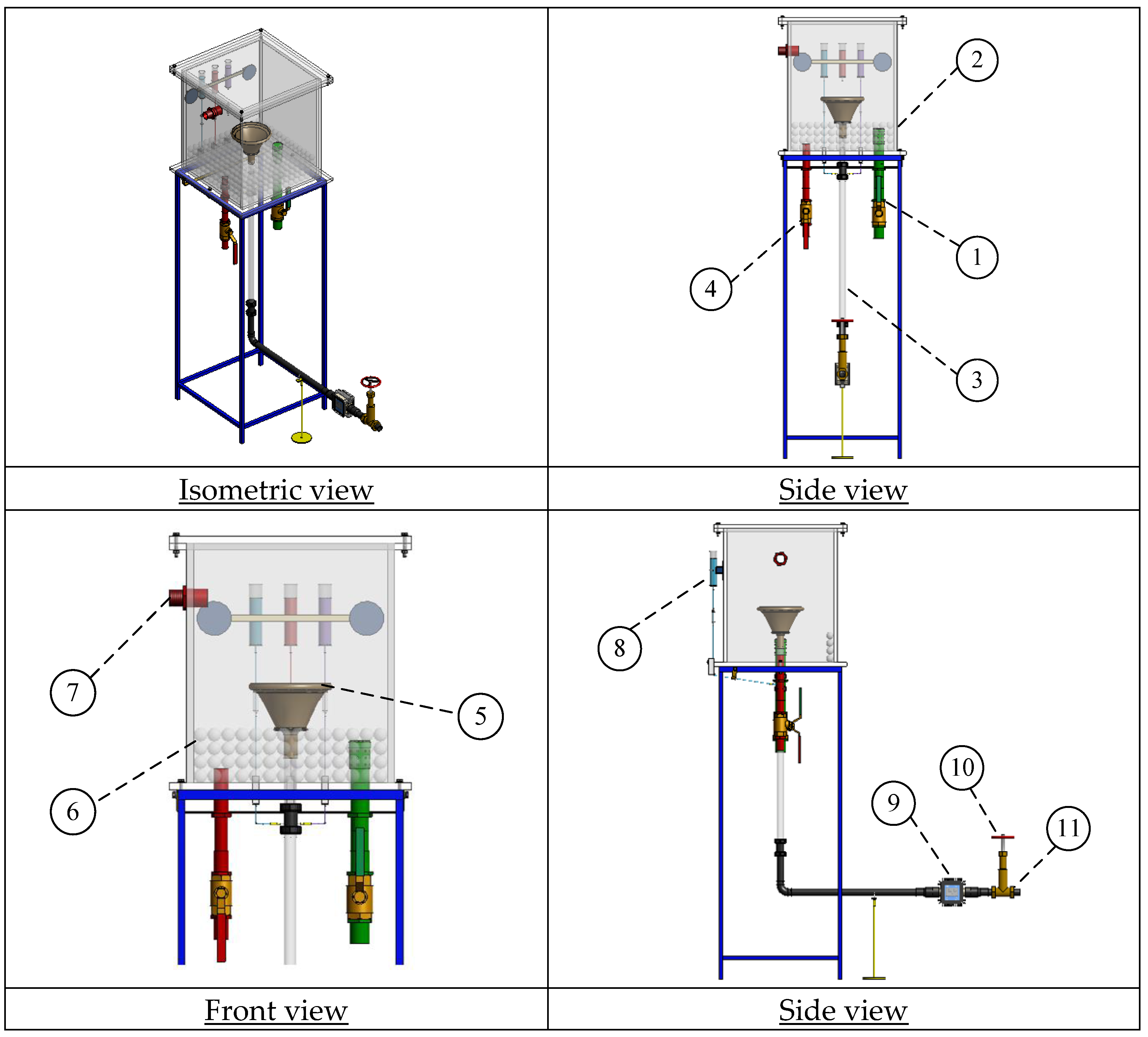
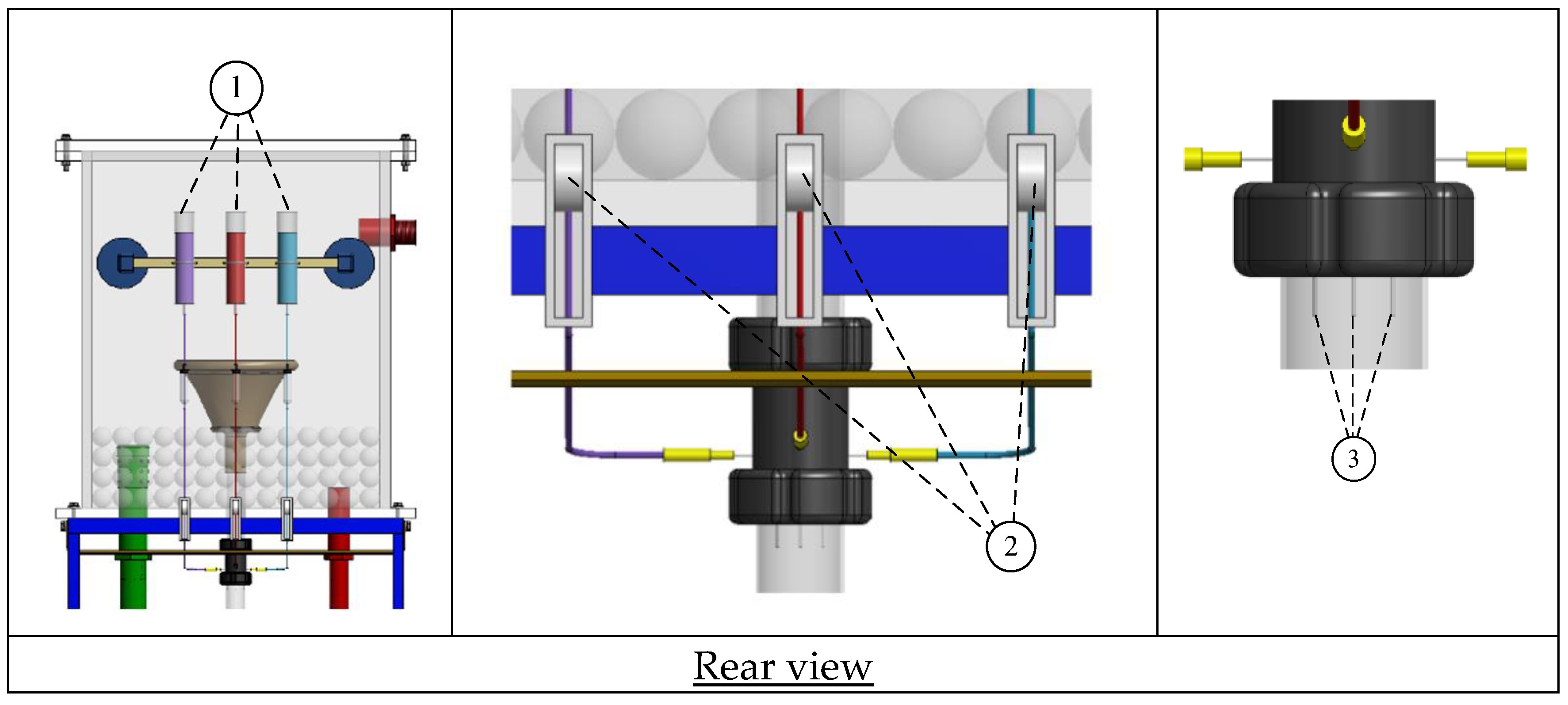
The flow characteristics in a round tube with knitted wire coil turbulators were examined using a dye injection method. Figure 4, Figure 5 and Figure 6 illustrate the details of the experimental setup. The apparatus included (1) an inlet pipe, (2) an overhead pipe, (3) an acrylic pipe, (4) an outlet pipe, (5) a bellmouth entry, (6) a glass ball, (7) an overflow pipe, (8) a dye system consisting of three dye tanks (red, blue, and violet) with needle valves to control dye injection rates, (9) a digital turbine flow meter, (10) a flow control valve, and (11) a drain pipe. Marbles were placed in the water reservoir to minimize ripples in the test setup. Additionally, spittoon tubing was installed at the inlet to ensure a uniform water flow into the test section. The test tube was a 1000 mm long acrylic tube with a 19 mm outer diameter and a 17.5 mm inner diameter. The experiments began by filling the dye tanks, adjusting the valves to regulate the dye injection rate, and controlling the opening and closing of the test section to introduce dye into the test vessel. Tests were conducted at three different Reynolds numbers, 1000, 2500, and 5000.

2.3. Experimental Heat Transfer Apparatus

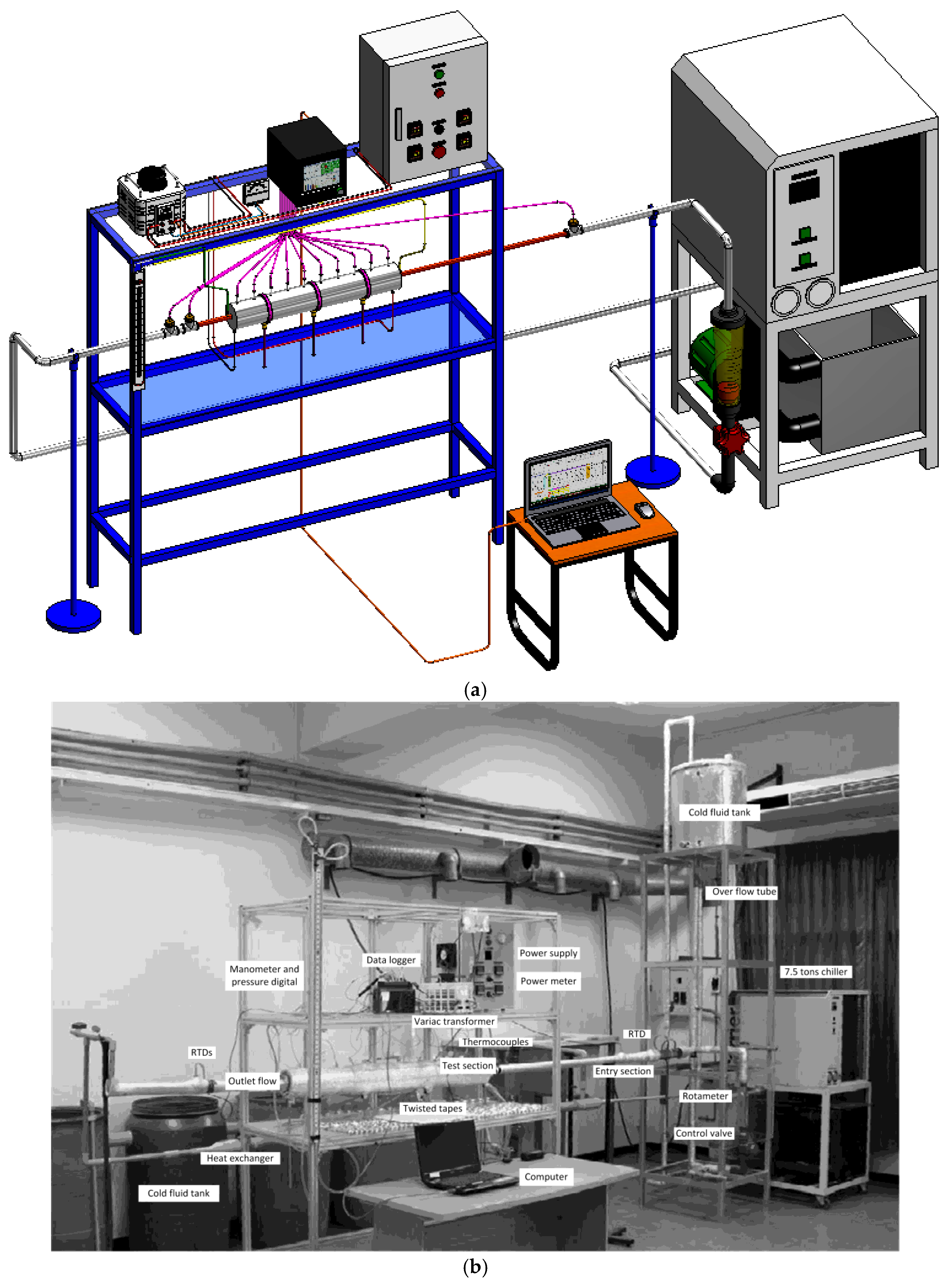
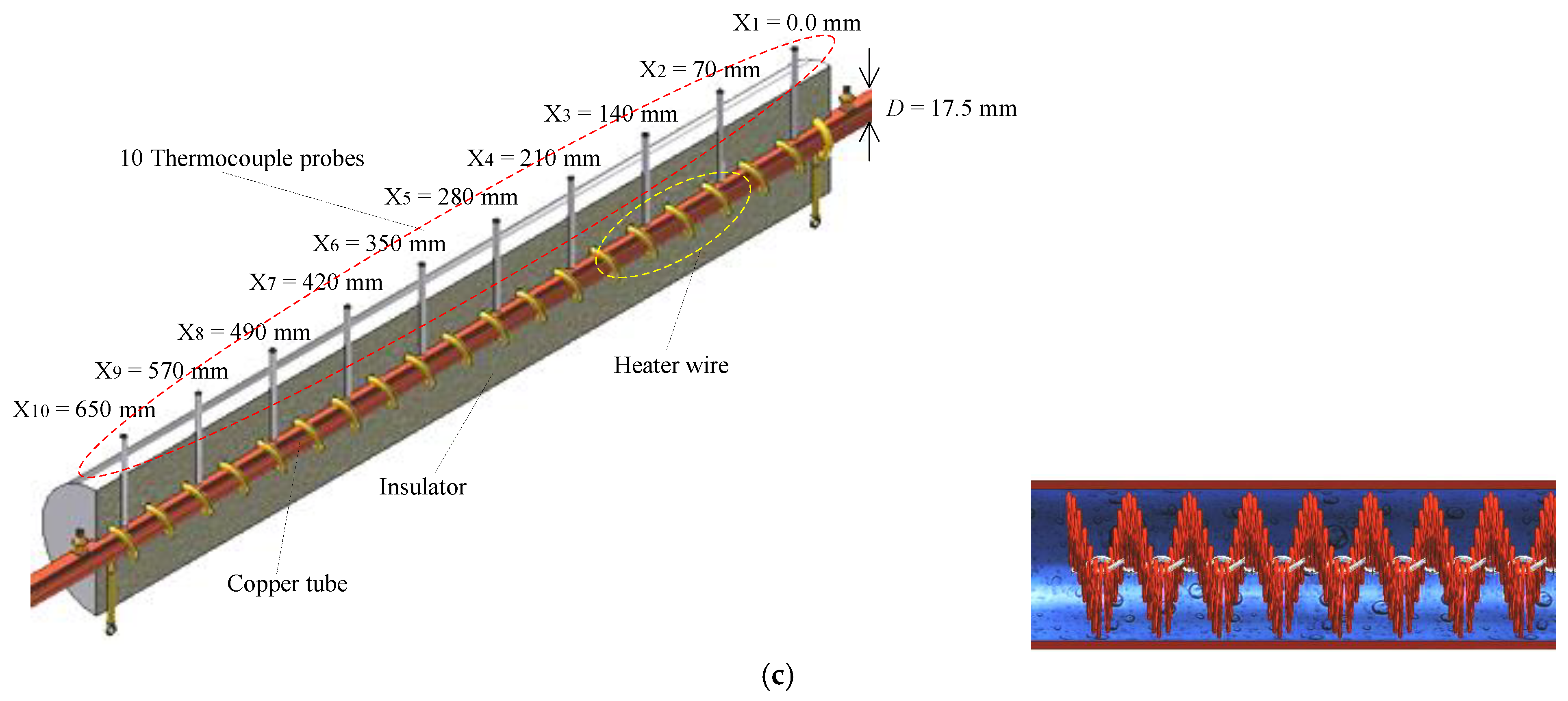
Figure 7 presents a schematic diagram of the apparatus used in the current work. The equipment in the setup included a heat exchanger tube (test section), electric heater (heat source), data logger, Variac transformer, centrifugal water pump, and water chiller. The heat exchanger tube was constructed from a 1.5 mm thick and 19 mm diameter circular copper tube. It comprised three sections: a 1.2 m (63D) calm section, a 1.0 m (53D) test section, and a 0.4 m (21D) outlet section. The 40D long calm section was sufficient to minimize upstream disturbances. In the experiments, the heater wire was coiled around the test tube with a consistent pitch length of 70 mm throughout the test section, where thermocouples were positioned along the test tube between the heater wire coils. Figure 6 illustrates the placement of seventeen type-T thermocouples for measuring local surface wall temperatures and resistance temperature detectors (RTDs) to monitor the inlet and outlet water temperatures (Ti and To). Four RTDs were used to ensure accurate inlet and outlet water temperature measurements—one at the tube core (Ti) and three at different radial locations to evaluate temperature variations. The measurement uncertainties for RTDs and type-T thermocouples were ±0.5 and 0.5 °C, respectively. The water volumetric flow rate was measured using a rotameter positioned upstream of the water chiller. It was adjusted to achieve the desired Reynolds number (5000 ≤ Re ≤ 15,000). This study examines the turbulent zone characterized by an initial Reynolds number of 5000 to 20,000. The test section was insulated with fiberglass along its axial length to minimize heat losses to the environment. A constant wall heat flux condition was maintained by supplying a 3.0-Amp steady current through an electric heater wire wrapped along the test section. Thermocouples were embedded in 0.5 mm V-shaped grooves and securely soldered to ensure optimal contact with the tube wall. Following soldering, high-temperature silicone insulation was applied to the grooves to shield the thermocouples from direct heat exposure. All experimental measurements were conducted under steady-state conditions. Steady-state conditions were assumed when all temperature readings at the inlet, outlet, and wall positions varied by less than ±0.2 °C over a 10 min period, and the electrical power input and mass flow rate remained constant. Furthermore, Table 2 and Table 3 have comprehensive information relating to knitted wire coils and the test conditions.
The module for temperature and pressure measurement is divided into two subsystems. Utilizing a constant-temperature plenum, the inlet water temperature was maintained at 25 °C. Water/Fluid temperatures were measured at both the inlet and exhaust using Pt100 RTDs (accuracy ±0.12 °C). The inlet RTD was installed at the centerline of the plenum outlet (r/D = 0.0), and three outlet RTDs were installed radially along the tube (r/D = 0, 0.3, and 0.45). In order to reduce the impact of radial temperature gradients, the arithmetic mean of the measurements at both the inlet and the outlet was implemented. Ten T-type thermocouples were distributed equally along the axial orientation of the test section, from 700 mm (40D) downstream of the inlet to 350 mm (20D) upstream of the outlet. To improve thermal contact, every thermocouple was placed into a blind hole with a diameter of 1.0 mm that was drilled to a depth of 0.33 mm, which was two-thirds of the wall thickness. The hole was then filled with thermal conductivity (k ≥ 1.2 W/m·K). Three auxiliary thermocouples were positioned at 120° intervals around the midsection of the tube to confirm circumferential temperature uniformity. A dual-gauge parallel monitoring strategy was utilized by the pressure measurement system. The overall pressure drop was measured using a pressure differential gauge (±1.0 Pa accuracy), while static pressures at both the inlet and the outlet were monitored using a digital pressure gauge (±0.1% accuracy). The total uncertainty in the pressure drop measurement was assured by comparison of the two readings, which was less than ±0.5%. Signals from the thermocouples, RTDs, power meter, and pressure gauges were simultaneously recorded by a multi-channel data recorder at a sampling interval of 1 s. Steady-state conditions were considered to have been achieved when the water temperature fluctuation remained within ±1.0 °C/min and the wall temperature difference within ±0.5 °C/min for a minimum of 30 s. In order to eliminate transient effects, data were collected continuously for 10 min after steady-state was attained, with the exception of the initial 2 min. The representative data point for each operating condition was the arithmetic mean of the remaining 8 min.

3. Data Reduction

In heat transfer enhancement research, data reduction is essential for evaluating key performance parameters, including the Nusselt number (Nu), friction factor (f), and thermal performance index (TPI). The Nusselt number, which represents the ratio of convective to conductive heat transfer, is calculated based on experimental temperature measurements. The friction factor, indicating flow resistance and pressure drop, is determined using measured pressure differentials across the test section. The performance factor assesses the overall efficiency of heat transfer enhancement by considering both heat transfer improvements and associated pressure losses.

3.1. Heat Transfer Evaluation

The mass flow rate of water is
m ˙ = ρ V .
where ρ is the water density, and V . is the volumetric flow rate.
The mean water velocity (U) is
U = ρ A m ˙
where ρ is the water density at the bulk water temperature, and A is the inlet cross-sectional area of the test section.
The Reynolds number is calculated from
Re = ρUD/μ
where D is the characteristic length and μ is the dynamic viscosity of water.
Qwater is calculated from the temperature difference:
Q water   =   m ˙ C p ( T o T i )
where Cp is the specific heat of water, Ti and To are the inlet and outlet temperatures of water, respectively.
The total heat generated under a constant wall heat flux is given by
Qt = V I
where V is the input voltage and I is the current.
The thermal equilibrium test found that the maximum difference between the heat from the electric source (Qt = V I) and the heat gained by the water (Qwater) is 7.2%. The heat gained by the water (Qwater) is assumed to be convective heat transfer (Qconv) under a steady state:
Qwater = Qconv
where
Q c o n v = h A ( T ~ w T b )
and T ~ w is an average of the surface wall temperatures (Tw) of the test section. A is the internal surface area of the heated tube.
T ~ w = Σ T w / 10
And
Tb = (To + Ti)/2
In Equations (4) and (7), an average heat transfer coefficient (h) can be obtained from
h = m ˙ C p ( T o T i ) / A ( T ~ w T b )
The average Nusselt number (Nu) is estimated from
Nu = hD/k

3.2. Friction Factor Evaluation

The pressure drop (ΔP) across the length of the test section (L) was used to calculate the friction factor (f) as
f = 2ΔPD/ρ L U2

3.3. Thermal Performance Index (TPI) Evaluation

The thermal performance index (TPI) considers not only the increased heat transfer but also the pressure drop penalty when calculating the efficiency of techniques for enhancing heat transfer. It is useful for evaluating the overall efficiency of a heat transfer system as it quantifies the trade-off between thermal enhancement and increased flow resistance. A higher thermal performance index (TPI) shows that a strategy successfully balances better heat transfer and lower friction losses. The concept described in [31] is implemented to compute the thermal performance index (TPI) at a constant pumping power.
TPI = (Nu/Nup)(f/fp)−1/3
where Nup and fp are the Nusselt number and friction factor for a circular tube with/without knitted wire coil turbulators installed, respectively.
Uncertainty analysis was performed using the McClintock method [32]. The uncertainties for the dimensionless Nusselt number (Nu) and the friction factor (f) were estimated at ±4.1 and ±3.4%, respectively. Table 4 presents all measured parameters along with the uncertainty analysis results.
Nusselt number (Nu):
Δ N u N u = 1 N u h N u Δ h 2 + D N u Δ D 2 + k N u Δ k w a t e r 2 0.5 = Δ h h 2 + Δ D D 2 0.5
where h = q T w T b
Δ h h = 1 h h q Δ q 2 + h T w Δ T w 2 + h T b Δ T b 2 0.5 = Δ q q 2 + Δ T w T w T b 2 + Δ T b T w T b 2 0.5
where q = 0.5 π D L V 2 / R + m ˙ C p T o T i
Friction factor (f):
Δ f f = 1 f f Δ P Δ Δ P 2 + f L Δ L 2 + f D Δ D 2 + f R e ( ) R e 2 0.5 = Δ Δ P Δ P 2 + Δ L L 2 + 3 Δ D D 2 + 2 Δ R e R e 2 0.5
where Δ Δ P Δ P = Δ h h and Δ R e R e = Δ m ˙ m ˙ 2 + Δ D D 2 0.5 .

4. Results and Discussion

This section presents the results and discussion on the thermal performance improvements achieved using knitted wire coil turbulators. Key dimensionless parameters, including the Nusselt number (heat transfer rate), friction factor (pressure drop), and overall thermal efficiency, are reported and analyzed. A thorough examination of the experimental data provides valuable insights into the effectiveness of knitted wire coil turbulators in optimizing heat exchanger design and enhancing energy efficiency.

4.1. Flow Visualization Results

4.1.1. The Tube Without Turbulator

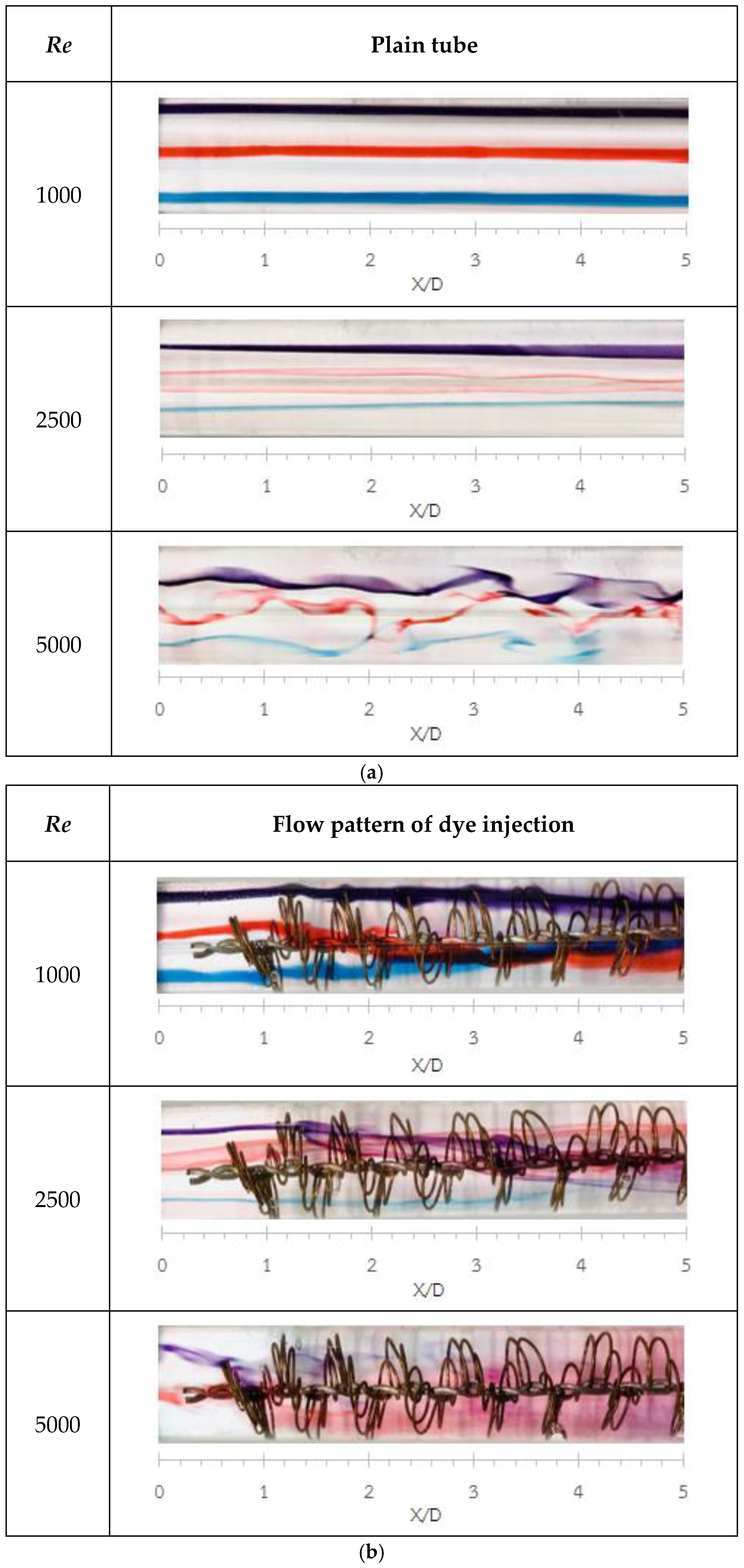
The flow behaviors in a tube with no turbulator assessed using a dye injection technique at Reynolds numbers (Re) of 1000, 2500, and 5000 are shown in Figure 8a. At Re = 1000, the flow is smooth and stable, with well-defined, parallel dye streaks indicating laminar behavior. At Re = 2500, small disturbances and waviness appear, marking the onset of transition. Finally, at Re = 5000, the flow becomes fully turbulent, with chaotic mixing, vortices, and irregular patterns.

4.1.2. The Tube with Knitted Wire Coil Turbulators

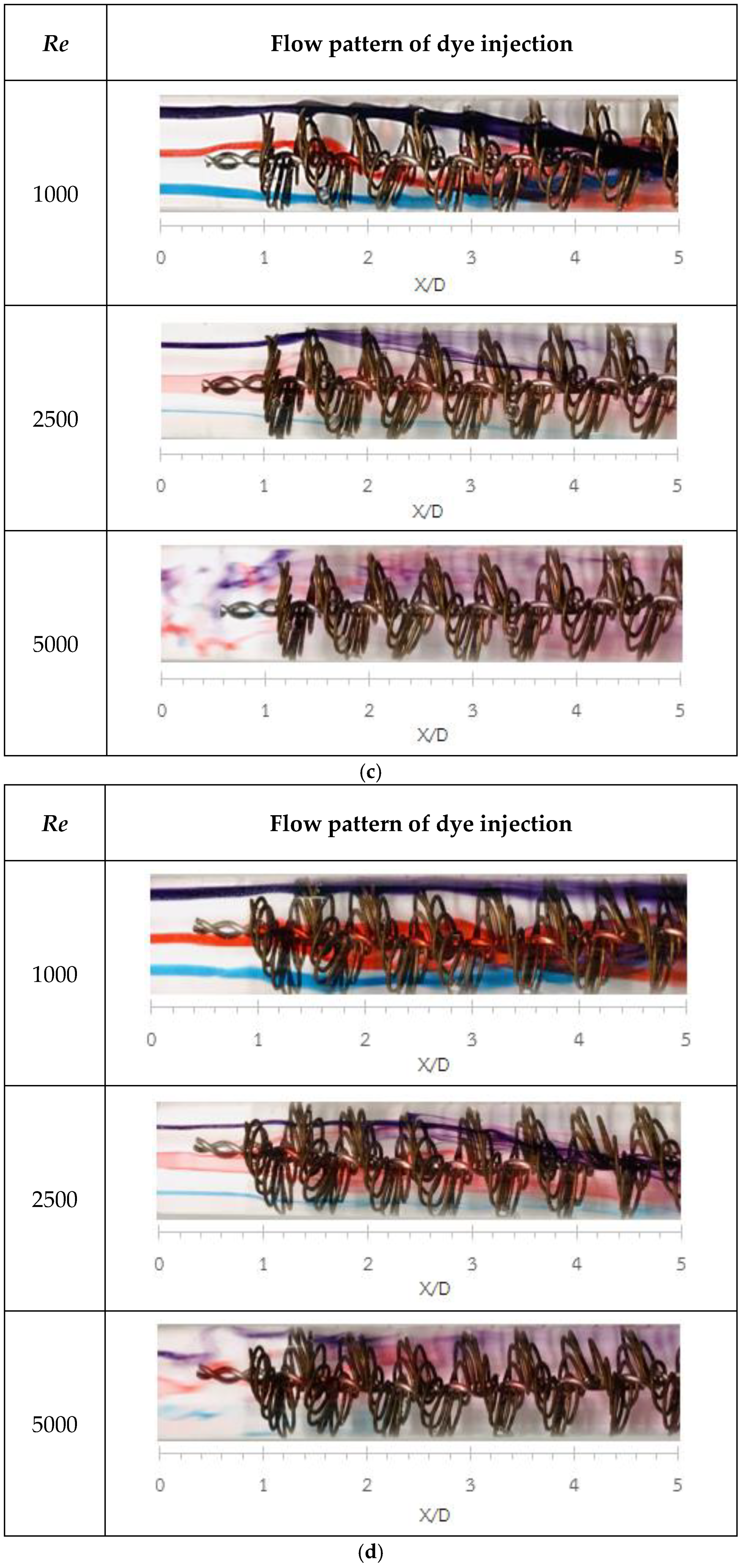
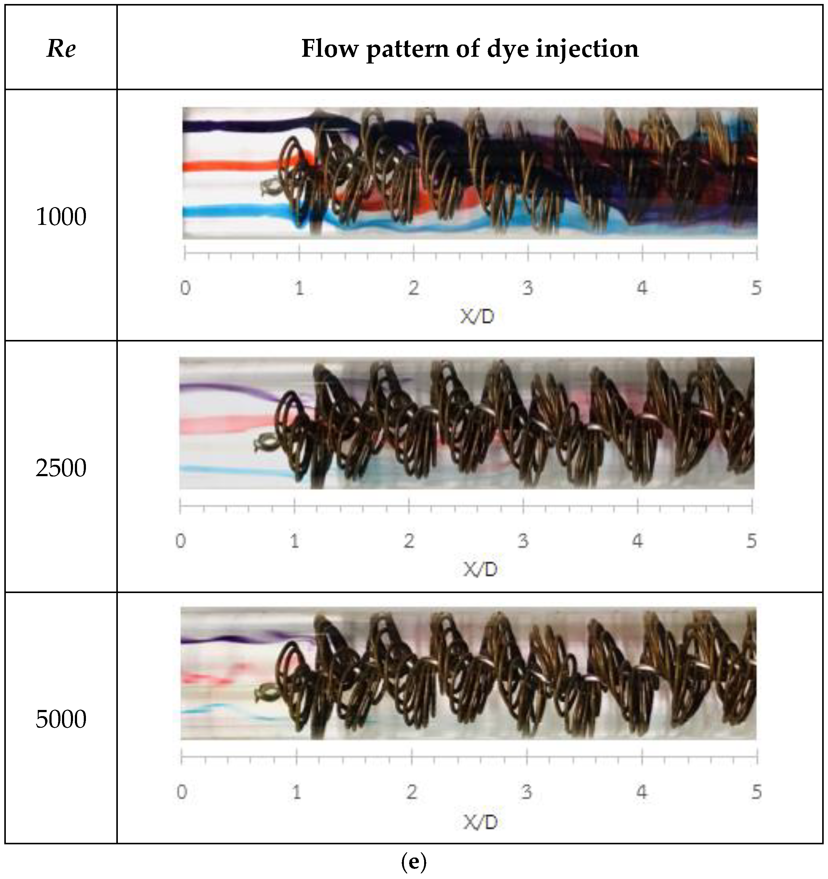
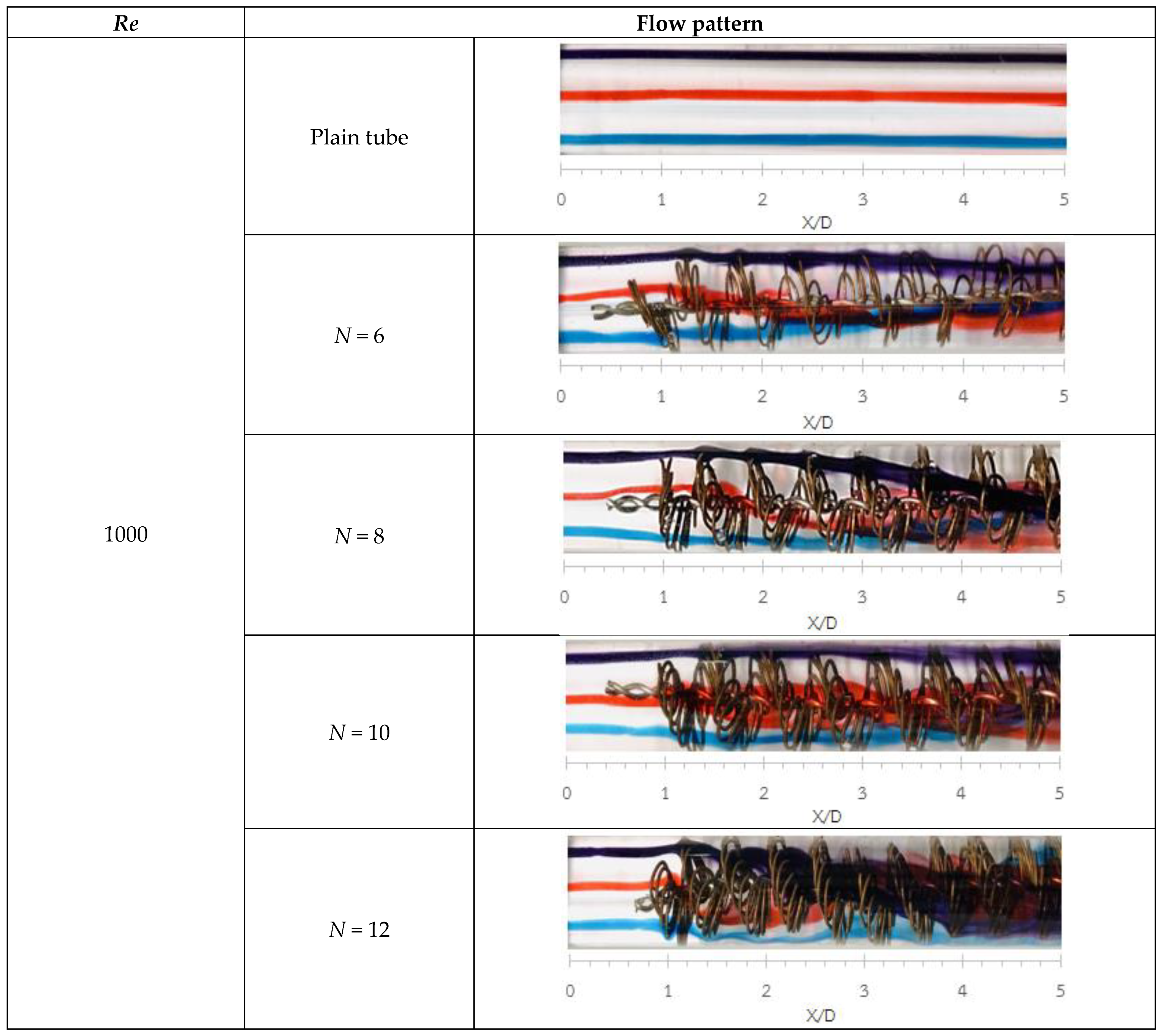
Figure 8b–d and Figure 9 illustrate the flow behavior in tubes equipped with knitted wire coil turbulators at wire loop number densities (N) of 6, 8, 10, and 12 loops. These experiments were conducted at Reynolds numbers of 1000, 2500, and 5000. The results indicate that flow characteristics varied based on the wire loop number density (N) and Reynolds number. At a Reynolds number of 1000 and N = 6, the dye streams showed only slight deviation from the main flow direction and remained relatively uniform within the range of X/D = 0.0–5.0. As N increased to 8 and 10, the dye streams exhibited greater deviation and dispersion; however, the original dye colors remained distinct with minimal mixing. When N was further increased to 12, the dye became noticeably dispersed within X/D = 1.0–3.0, and beyond X/D = 3.0, the colors gradually merged, forming new blended shades. At Re = 2500 and N = 6.0, the dye streaks began to disperse immediately upon impinging on the wire coil at X/D = 1.0, with clear mixing observed when X/D ≥ 3.0. Increasing N to 8 and 10 resulted in stronger dye dispersion and enhanced mixing, although the original color of the streaks could still be identified for X/D ≤ 2. When N = 12, intensive mixing occurred from X/D = 1.0, and beyond X/D = 2.0, the dye streams merged completely, producing distinct new color tones. At Re = 5000, the dye streams for all N values mixed almost instantaneously upon striking the wire coil at X/D = 1.0. The rate and intensity of color blending increased progressively with higher N, indicating stronger flow disturbance and enhanced mixing effectiveness.
These observations confirm that increasing both N and Re intensifies flow turbulence, promotes dye spreading, and strengthens the interaction between adjacent streams—resulting in significantly improved mixing performance.
Figure 10 illustrates the flow patterns in a tube equipped with a knitted wire coil turbulator at different axial locations. In the upstream region (X/D < 1.0), the velocity profile remained relatively uniform before reaching the turbulator. As the flow approached the turbulator at X/D ≈ 1.0, it began to interact with the structure, generating localized disturbances. Between X/D ≈ 1.0–3.0, the wire coil induced secondary flows, increasing turbulence intensity. Additionally, shear layers developed, contributing to enhanced heat transfer. Further downstream, in the region of X/D ≈ 3.0–5.0, the turbulent structures continue to evolve, resulting in increasingly chaotic flow behavior. In the fully developed region (X/D ≈ 5.0–10), the flow became fully chaotic, leading to excellent mixing between the fluid at the tube center and the wall, thereby enhancing heat transfer.

4.2. Validation of a Plain Tube

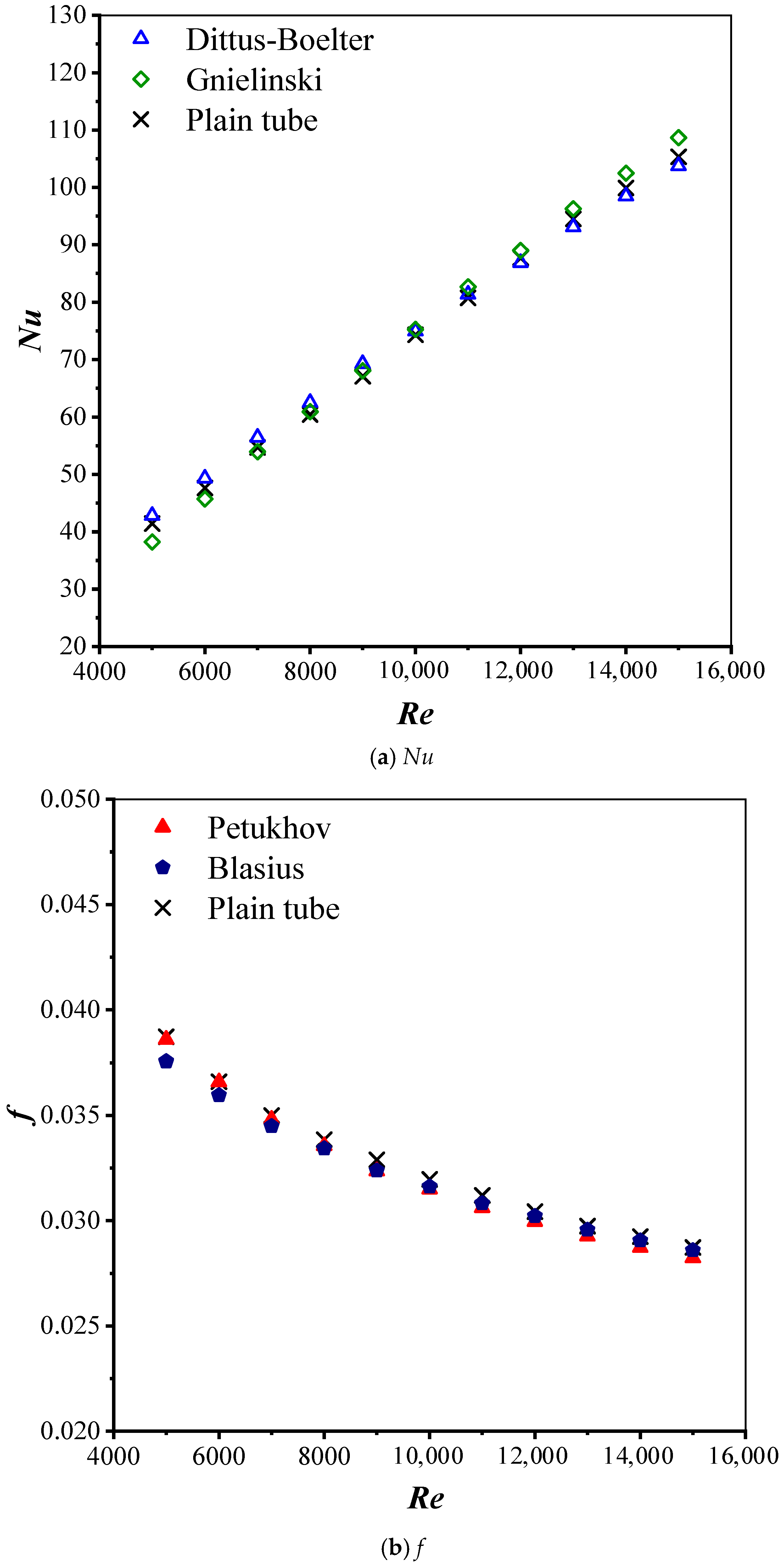
The experimentally obtained Nusselt number and friction factor data for the tube with no turbulators were validated using standard correlations to assess the reliability of the setup. The Nusselt number results were compared with the standard empirical correlation by Dittus-Boelter [33].
f = 0.316 Re 0.25
The friction factor (f) results were compared with the Blasius correlation [33] under similar conditions:
f = 0.316 Re 0.25
Figure 11a,b demonstrate good agreement between the experimental results of the present data and standard correlations, with deviations not exceeding 3.9% for the Nusselt number (Nu) and 5.2% for the friction factor (f). This finding confirms the reliability of the experimental data and setup. Consequently, the experimental results of the plain tube serve as a valid reference for assessing the performance of tubes with knitted wire coil turbulators.

4.3. Heat Transfer Results

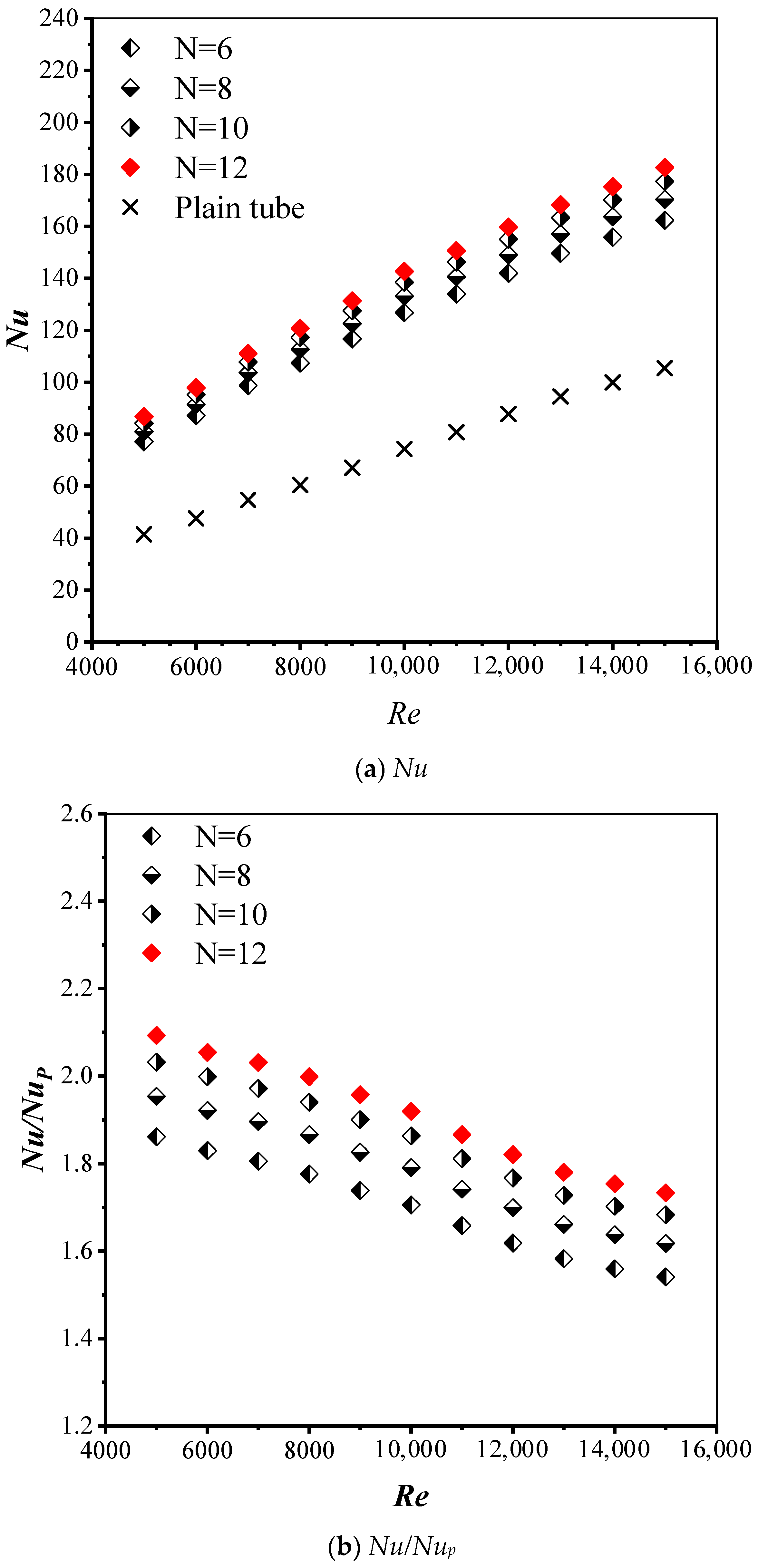
The effect of knitted wire coil turbulators with different wire loop number densities (N = 6, 8, 10, and 12) on the heat transfer rate is presented in Figure 12a,b. As expected, the turbulators significantly enhanced the heat transfer rate (Nusselt number). The Nusselt number increased with higher wire loop number densities (N) and Reynolds numbers (Re). These results align well with the flow behaviors observed using the dye injection technique, discussed in Section 4.1. Compared to the plain tube, the use of knitted wire coil turbulators with N = 6, 8, 10, and 12 led to increased Nusselt numbers by 86.1, 95.4, 103.2, and 109.3%, respectively. Turbulators with N = 12 outperformed those with N = 6, 8, and 10 by 12.5, 7.17, and 3%, respectively. This can be attributed to the greater secondary flows generated by denser knitted wire coils, which subsequently interact with one another, leading to stronger turbulence and enhanced heat transfer.
Additionally, the Nusselt number increased with the Reynolds number. As the Reynolds number rises, the flow becomes more turbulent, enhancing fluid mixing and improving convective heat transfer between the fluid and the surface. This leads to a higher heat transfer rate, reflected by an increased Nusselt number. However, the ratio of the Nusselt number with turbulators to that with no turbulator (Nu/Nup) tended to decrease with the Reynolds number since heat transfer is already relatively efficient at higher Reynolds numbers. As the flow becomes more turbulent, the heat transfer improvement from enhancement techniques diminishes, leading to a reduction in the enhancement ratio despite the higher Nusselt number.

4.4. Friction Factor Results

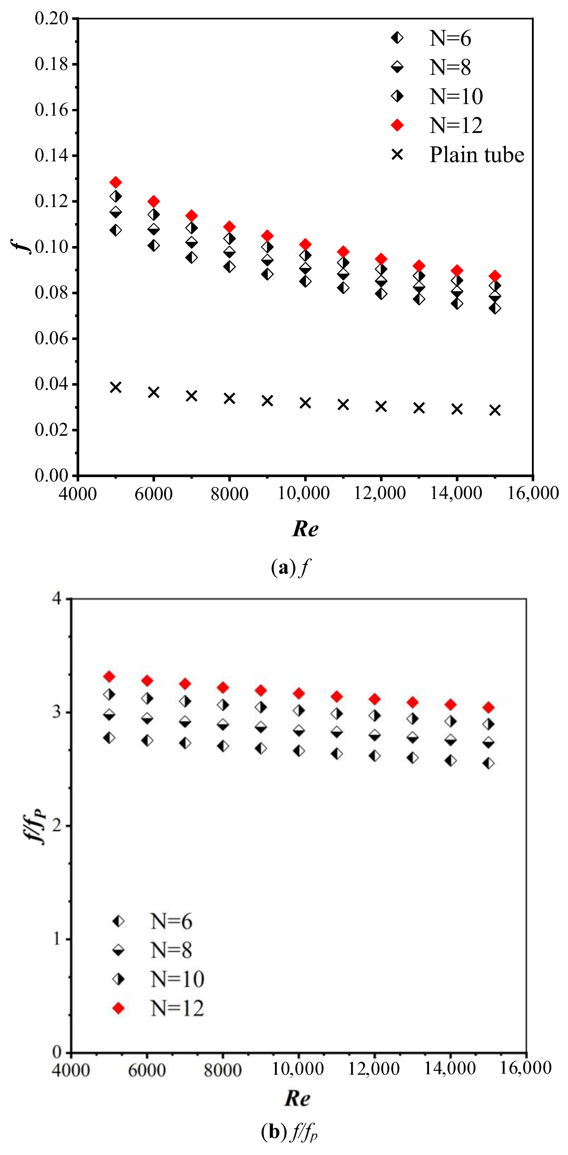
Figure 13a,b present the friction factor results over the studied Reynolds number range for a tube fitted with knitted wire coil turbulators at different wire loop number densities (N = 6, 8, 10, and 12). Increasing the Reynolds number (Re) caused a slight reduction in the friction factor (f) and the ratio of the friction factor with a turbulator to that without one (ft/fp). The presence of knitted wire coil turbulators significantly increased friction factors by disrupting the laminar boundary layer, inducing turbulence, and enhancing momentum exchange and shear stress. This led to a higher pressure drop and flow resistance. Additionally, the friction factor increased with wire loop number density (N). The friction factors for tubes with knitted wire coil turbulators at N = 6, 8, 10, and 12 were 1.77, 1.97, 2.15, and 2.31 times greater than that of a plain tube, respectively. At N = 12, the friction factor enhancements were 19.42, 11.54, and 5.06% greater compared to N = 6, 8, and 10, respectively. This increase is attributed to the greater blockage effect at higher wire loop number densities.

4.5. Thermal Performance Index Results

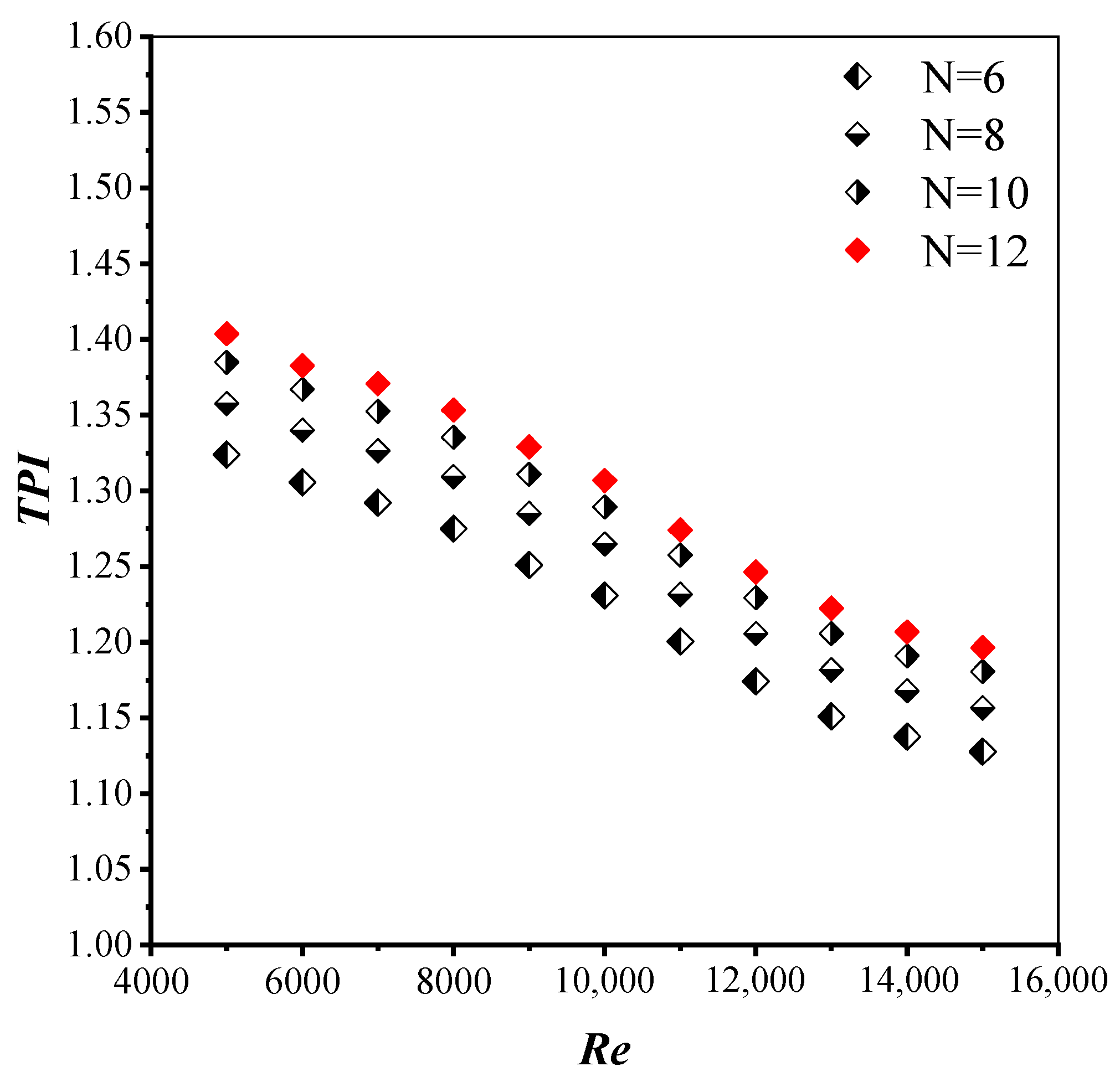
Figure 14 illustrates the thermal performance index (TPI) results for a tube fitted with knitted wire coil turbulators at different wire loop number densities (N = 6, 8, 10, and 12). The TPI values were evaluated under constant pumping power using Equation (13). In general, TPI decreased with increasing Reynolds numbers due to a significantly greater pressure drop, which outweighed the heat transfer improvement. However, all knitted wire coil turbulators had TPI values above unity throughout the Reynolds number range, demonstrating their effectiveness in energy savings. At constant Reynolds numbers, the TPI increased with wire loop number density. The knitted wire coil turbulators with N = 6, 8, 10, and 12 achieved maximum TPI values of 1.32, 1.36, 1.38, and 1.4, respectively. The highest density (N = 12) outperformed N = 6, 8, and 10 by approximately 6.23, 3.46, and 1.4%, respectively. The maximum TPI, 1.4, was observed at a Reynolds number of 5000 for the tube with N = 12.
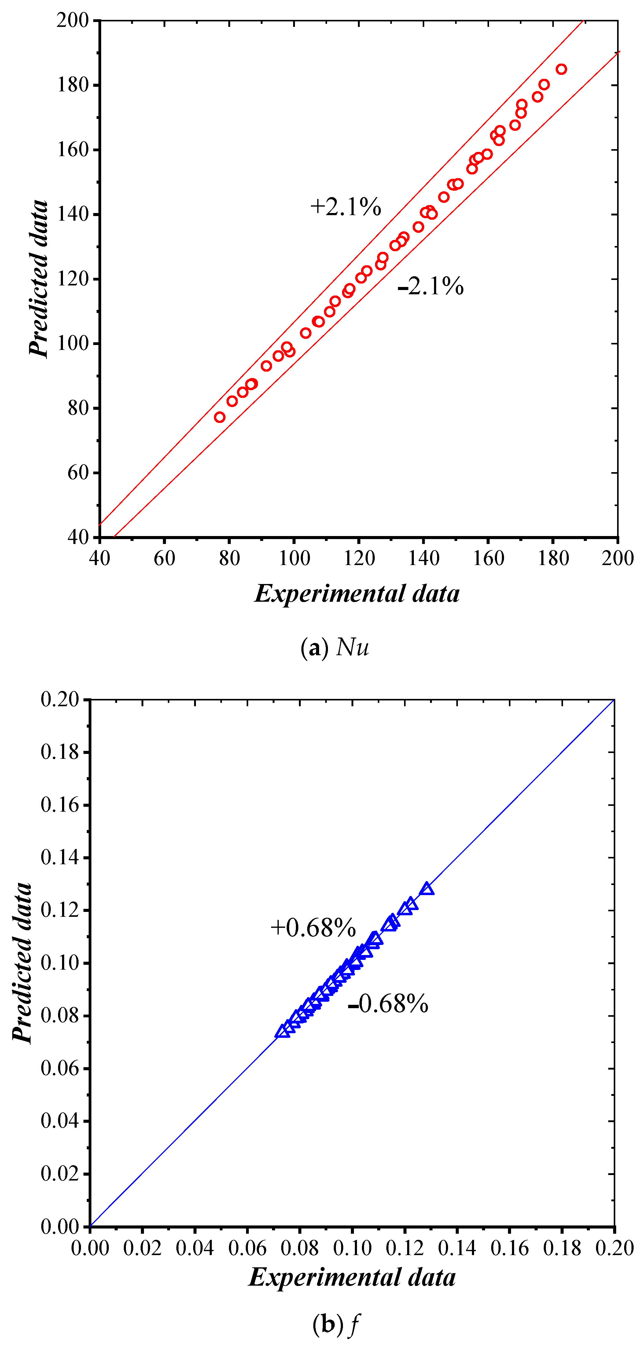
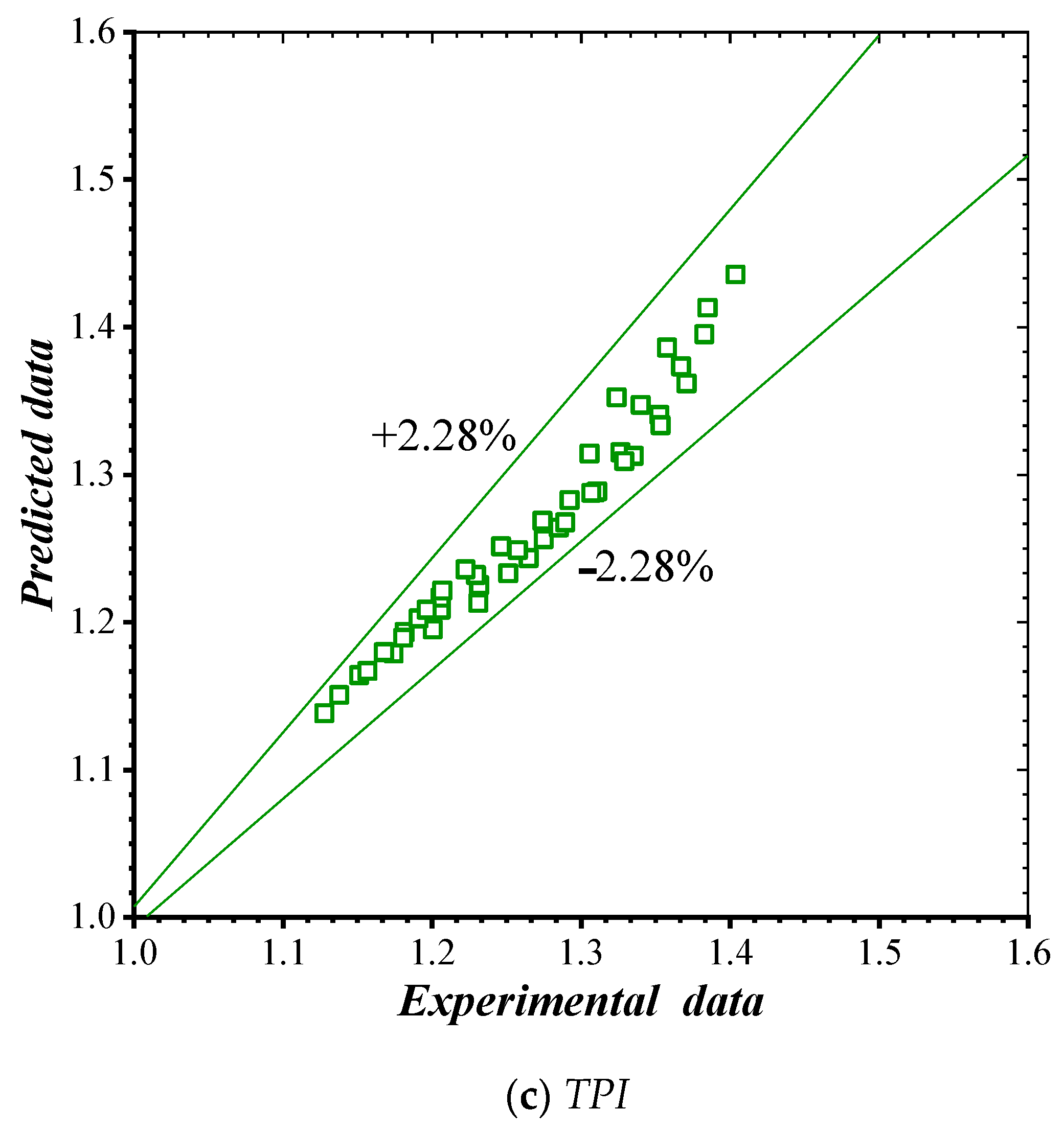
Least squares regression analysis was employed to establish experimental correlations for the Nusselt number (Nu), friction factors (f), and thermal performance index (TPI) using a tube mounted with knitted wire coil turbulators. This methodology employed water as the test fluid under turbulent conditions with Reynolds numbers ranging from 5000 to 15,000, heat flux at 600 W/m2, and wire loop number densities (N = 6, 8, 10, and 12 loops per pitch) as the independent variable.
N u = 0.097 Re 0.67 Pr 0.4 N 0.16
f = 1.29 Re 0.35 N 0.25
T P I = 4.41 Re 0.157 N 0.09
The Nusselt number values obtained from Equation (19), the friction factor from Equation (20), and the thermal performance index (TPI) from Equation (21) for the turbulent regime (5000 ≤ Re ≤ 15,000) are compared with the present experimental data and shown in Figure 15a–c. The fitted values match the experimental results within ±2.1% for the Nusselt number, ±0.7% for the friction factor, and ±2.28% for the thermal performance index (TPI).

4.6. Comparison with Works

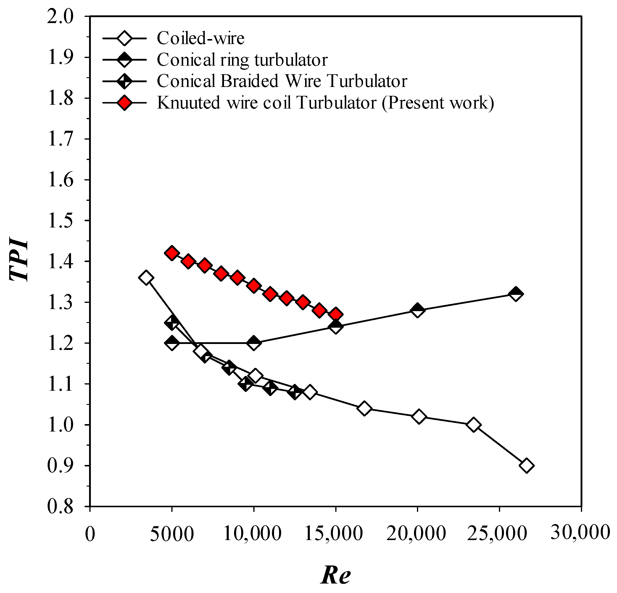
The thermal performance index of the knitted wire coil turbulators at wire loop number densities (N = 12 loops) is compared to that of previous modified turbulators, including the coiled-wire [6], conical ring turbulator [34], and conical braided wire turbulator [35]. Figure 16 illustrates this comparison. A comparison was conducted between all of the turbulators that have been identified at a comparable Reynolds number (Re). The thermal performance index of the present work is higher than that of other turbulators at low Reynolds numbers, as evidenced by the figure. Conversely, in the turbulent flow region, the present work has the lowest thermal performance index, which is lower than that of the conical ring turbulator [34]. It is intriguing to observe that the thermal performance index of knitted wire coil turbulators is greater than unity for all Reynolds numbers investigated. This suggests that they can be utilized effectively for energy conservation and compactness objectives in comparison to other modified turbulators. It is evident that the thermal performance index of the present knitted wire coil turbulators is significantly constrained by the presence of high flow obstruction or friction.
It is crucial to note that the knitted wire coil turbulator shape exhibits not only exceptional thermal performance but also practical advantages in terms of fabrication. The design necessitates only a meshing wire. This simplicity results in increased feasibility for commercial-scale heat exchanger applications, where effectiveness and manufacturing simplicity are critical factors. In light of this, the knitted wire coil design for a turbulator is a greatly prospective approach for the development of potential thermal technology.

5. Conclusions

The influences of knitted wire coil turbulators on heat transfer augmentation for 5000 ≤ Re ≤ 15,000 are reported. Knitted wire coil turbulators with different wire loop number densities (N = 6, 8, 10, and 12) were examined using water as a working fluid. Based on this investigation, the key conclusions are summarized below.
The use of knitted wire coil turbulators significantly increased the Nusselt number (Nu) and friction factor (f).
Increasing the wire loop number density (N) enhanced the heat transfer rate, friction loss, and thermal performance index (TPI).
Compared to the case with no turbulator, the use of knitted wire coil turbulators with N = 6, 8, 10, and 12 increased the Nusselt number by 86.1, 95.4, 103.2, and 109.3%, respectively.
The friction factors for tubes with knitted wire coil turbulators at N = 6, 8, 10, and 12 were 1.77, 1.97, 2.15, and 2.31 times higher than that of a plain tube, respectively.
The maximum TPI values achieved for knitted wire coil turbulators with N = 6, 8, 10, and 12 were 1.32, 1.36, 1.38, and 1.4, respectively, with N = 12 outperforming N = 6, 8, and 10 by approximately 6.23, 3.46, and 1.4%, respectively.

Author Contributions

Conceptualization, K.W., V.C. and S.E.-a.; methodology, K.W. and P.P.; software, P.P.; validation, K.W. and P.P.; formal analysis, K.W. and V.C.; investigation, K.W. and T.S.W.; data curation, K.W.; writing—original draft preparation, K.W., and V.C.; writing—review and editing, T.S.W.; visualization, K.W., P.P. and V.C.; supervision, N.M., M.H. and S.E.-a.; project administration, V.C.; funding acquisition, V.C. All authors have read and agreed to the published version of the manuscript.

Funding

This research was funded by School of Engineering, King Mongkut’s Institute of Technology Ladkrabang grant number [2568-02-01-026] and The APC was funded by [King Mongkut’s Institute of Technology Ladkrabang].

Institutional Review Board Statement

Not applicable.

Informed Consent Statement

Not applicable.

Data Availability Statement

The raw data supporting the conclusions of this article will be made available by the authors on request.

Acknowledgments

The authors acknowledge with appreciation the School of Engineering, King Mongkut’s Institute of Technology Ladkrabang for financial support of this research (Grant No. 2568-02-01-026).

Conflicts of Interest

On behalf of all authors, the corresponding author states that there are no conflicts of interest.

Nomenclature

TPIThermal performance index
ATest cross-section area, m2
CpSpecific heat at constant pressure, J/kg K
DTest section diameter, m
fFriction factor
hHeat transfer coefficient, W/m2 K
IElectrical current, Amps
kThermal conductivity, W/m K
LLength of the test section, m
m ˙ Mass flow rate of water, kg/s
NuNusselt number
ΔPPressure drop, Pa
PrPrandtl number
q Heat flux, W/m2
QHeat transfer rate, W
QconvConvective heat transfer, W
QtTotal heat generated under constant wall heat flux, W
QwHeat absorbed by the water, W
ReReynolds number
TTemperature, K
T ~ Average temperature, K
UVelocity, m/s
VInput voltage, volt
V . Volume metric flow rate, m3/s
Greek symbols
ΔPPressure drop, Pa
μWater dynamic viscosity, Ns/m−2
ρWater density, kg/m3
Subscripts
bBulk
iInlet
oOutlet
pPlain tube
wWall

References

  1. Fan, A.; Deng, J.; Guo, J.; Liu, W. A Numerical Study on Thermo-Hydraulic Characteristics of Turbulent Flow in a Circular Tube Fitted with Conical Strip Inserts. Appl. Therm. Eng. 2011, 31, 2819–2828. [Google Scholar] [CrossRef]
  2. Govindasamy, M.; Ezhumalai, M.; Dhairiyasamy, R.; Varshney, D.; Singh, S.; Gabiriel, D. Comprehensive Investigation into the Thermal Performance of Nanofluid-Enhanced Heat Pipes for Advanced Thermal Management Systems. Eng 2025, 6, 55. [Google Scholar] [CrossRef]
  3. Gunes, S.; Ozceyhan, V.; Buyukalaca, O. The Experimental Investigation of Heat Transfer and Pressure Drop in a Tube with Coiled Wire Inserts Placed Separately from The Tube Wall. Appl. Therm. Eng. 2010, 30, 1719–1725. [Google Scholar] [CrossRef]
  4. Karakaya, H.; Durmus, A. Heat Transfer and Exergy Loss in Conical Spring Turbulators. Int. J. Heat Mass Transf. 2013, 60, 756–762. [Google Scholar] [CrossRef]
  5. San, J.Y.; Huang, W.C.; Chen, C.A. Experimental Investigation on Heat Transfer and Fluid Friction Correlations for Circular Tubes with Coiled-Wire Inserts. Int. Commun. Heat Mass. Transf. 2015, 6, 8–14. [Google Scholar] [CrossRef]
  6. Keklikcioglu, O.; Ozceyhan, V. Experimental Investigation on Heat Transfer Enhancement in a Circular Tube with Equilateral Triangle Cross Sectioned Coiled-Wire Inserts. Appl. Therm. Eng. 2018, 131, 686–695. [Google Scholar] [CrossRef]
  7. Nanan, K.; Yongsiri, K.; Wongcharee, K.; Thianpong, C.; Eiamsa-ard, S. Heat Transfer Enhancement by Helically Twisted Tapes Inducing Co- and Counter-Swirl Flows. Int. Commun. Heat Mass. Transf. 2013, 46, 67–73. [Google Scholar] [CrossRef]
  8. Akhavan-Behabadi, M.A.; Kumar, R.; Salimpour, M.R.; Azimi, R. Pressure Drop and Heat Transfer Augmentation Due to Coiled Wire Inserts During Laminar Flow of Oil Inside a Horizontal Tube. Int. J. Therm. Sci. 2010, 49, 373–379. [Google Scholar] [CrossRef]
  9. Ozceyhan, V.; Gunes, S.; Buyukalaca, O.; Altuntop, N. Heat Transfer Enhancement in a Tube Using Circular Cross Sectional Rings Separated From Wall. Appl. Therm. Eng. 2006, 83, 280–298. [Google Scholar] [CrossRef]
  10. Gunes, S.; Ozceyhan, V.; Buyukalaca, O. Heat Transfer Enhancement in a Tube with Equilateral Triangle Cross Sectioned Coiled Wire Inserts. Exp. Therm. Fluid Sci. 2010, 34, 684–691. [Google Scholar] [CrossRef]
  11. Hong, Y.; Du, J.; Wang, S.; Huang, S.M.; Ye, W.B. Heat Transfer and Fluid Flow Behaviors in aTube with Modified Wire Coils. Int. J. Heat Mass Transf. 2018, 124, 1347–1360. [Google Scholar] [CrossRef]
  12. Eiamsa-ard, S.; Koolnapadol, N.; Promvonge, P. Heat Transfer Behavior in a Square Duct with Tandem Wire Coil Element Insert. Chin. J. Chem. Eng. 2012, 20, 863–869. [Google Scholar] [CrossRef]
  13. Abdul Hamid, K.; Azmi, W.H.; Mamat, R.; Sharma, K.V. Heat Transfer Performance of Tio2–Sio2 Nanofluids in a Tube with Wire Coil Inserts. Appl. Therm. Eng. 2019, 152, 275–286. [Google Scholar] [CrossRef]
  14. Dyga, R.; Płaczek, M. Efficiency of Heat Transfer in Heat Exchangers with Wire Mesh Packing. Int. J. Heat Mass Transf. 2010, 53, 5499–5508. [Google Scholar] [CrossRef]
  15. Xing, F.; Xie, J.; Xu, J. Modulated Heat Transfer Tube with Mesh Cylinder Inserted. Int. Commun. Heat Mass. Transf. 2014, 56, 15–24. [Google Scholar] [CrossRef]
  16. Liu, Y.; Xu, G.; Luo, X.; Li, H.; Ma, J. An Experimental Investigation on Fluid Flow and Heat Transfer Characteristics of Sintered Woven Wire Mesh Structures. Appl. Therm. Eng. 2015, 80, 118–126. [Google Scholar] [CrossRef]
  17. Kurian, R.; Balaji, C.; Venkateshan, S.P. Experimental Investigation of Near Compact Wire Mesh Heat Exchangers. Appl. Therm. Eng. 2016, 108, 1158–1167. [Google Scholar] [CrossRef]
  18. Fu, Y.; Wen, J.; Zhang, C. An Experimental Investigation on Heat Transfer Enhancement of Sprayed Wire-Mesh Heat Exchangers. Int. Commun. Heat Mass. Transf. 2017, 112, 699–708. [Google Scholar] [CrossRef]
  19. Kotresha, B.; Gnanasekaran, N. Determination of Interfacial Heat Transfer Coefficient for The Flow Assisted Mixed Convection Through Brass Wire Mesh. Int. J. Therm. Sci. 2019, 138, 98–108. [Google Scholar] [CrossRef]
  20. Sayed, M.A.; ELdein Hussin, A.M.T.A.; Mahmoud, N.A.; Aboelsoud, W. Performance Evaluation of Wire Mesh Heat Exchangers. Appl. Therm. Eng. 2020, 169, 114891. [Google Scholar] [CrossRef]
  21. Nanan, K.; Pimsarn, M.; Jedsadaratanachai, W.; Eiamsa-ard, S. Heat Transfer Augmentation Through the Use of Wire-Rod Bundles Under Constant Wall Heat Flux Condition. Int. Commun. Heat Mass. Transf. 2013, 48, 133–140. [Google Scholar] [CrossRef]
  22. Naphon, P.; Suchana, T. Heat Transfer Enhancement and Pressure Drop of the Horizontal Concentric Tube with Twisted Wires Brush Inserts. Int. Commun. Heat Mass. Transf. 2011, 38, 236–241. [Google Scholar] [CrossRef]
  23. Bhuiya, M.M.K.; Chowdhury, M.S.U.; Islam, M.; Ahamed, J.U.; Khan, M.J.H.; Sarker, M.R.I.; Saha, M. Heat Transfer Performance Evaluation for Turbulent Flow Through a Tube with Twisted Wire Brush Inserts. Int. Commun. Heat Mass. Transf. 2012, 39, 1505–1512. [Google Scholar] [CrossRef]
  24. Yu, C.; Zhang, H.; Wang, Y.; Zeng, M.; Gao, B. Numerical Study on Turbulent Heat Transfer Performance of Twisted Oval Tube with Different Cross Sectioned Wire Coil. Case Stud. Therm. Eng. 2020, 22, 100759. [Google Scholar] [CrossRef]
  25. Dang, W.; Wang, L.B. Convective Heat Transfer Enhancement Mechanisms in Circular Tube Inserted with a Type of Twined Coil. Int. Commun. Heat Mass. Transf. 2021, 169, 120960. [Google Scholar] [CrossRef]
  26. Keklikcioglu, O.; Ozceyhan, V. Heat Transfer Augmentation in a Tube with Conical Wire Coils Using a Mixture of Ethylene Glycol/Water as a Fluid. Int. J. Therm. Sci. 2022, 171, 107204. [Google Scholar] [CrossRef]
  27. Chompookham, T.; Chingtuaythong, W.; Chokphoemphun, S. Influence of a Novel Serrated Wire Coil Insert on Thermal Characteristics and Air Flow Behavior in a Tubular Heat Exchanger. Int. J. Therm. Sci. 2022, 171, 107184. [Google Scholar] [CrossRef]
  28. Subirana, A.M.; Solano, J.P.; Herrero-Martín, R.; García, A.; Pérez-García, J. Mixed Convection Phenomena in Tubes with Wire Coil Inserts. TSEP 2023, 42, 101839. [Google Scholar]
  29. Hashemian, M.; Jafarmadar, S.; Ayed, H.; Wae-hayee, M. Thermal-Hydrodynamic and Exergetic Study of Two-Phase Flow in Helically Coiled Pipe with Helical Wire Insert. Case Stud. Therm. Eng. 2022, 30, 101718. [Google Scholar] [CrossRef]
  30. Hong, Y.; Du, J.; Wang, S.; Ye, W.B.; Huang, S.M. Turbulent Thermal-Hydraulic and Thermodynamic Characteristics in a Traverse Corrugated Tube Fitted with Twin and Triple Wire Coils. Int. J. Heat Mass Transf. 2019, 130, 483–495. [Google Scholar] [CrossRef]
  31. Webb, R.L.; Kim, N.H. Principles of Enhanced Heat Transfer, 2nd ed.; Taylor & Francis: New York, NY, USA, 2005; p. 785. [Google Scholar]
  32. Kline, S.J.; McClintock, F.A. Describing Uncertainties in Single Sample Experiments. Mech. Eng. 1953, 75, 3–8. [Google Scholar]
  33. Bergman, T.L.; Lavine, A.S.; Incropera, F.P.; Dewitt, P.D. Fundamentals of Heat and Mass Transfer, 7th ed.; John Wiley & Sons, Inc.: Hoboken, NJ, USA, 2011. [Google Scholar]
  34. Wang, H.; Al-amir, Q.R.; Jasim, D.J.; Ayed, H.; Mouldi, A.; Deifalla, A.; Mahariq, I. Enhancing the Heat Transfer Efficiency of an Engine Heat Exchanger Through the Utilization of an Innovative Conical Braided Wire Turbulator. Case Stud. Therm. Eng. 2024, 61, 104873. [Google Scholar] [CrossRef]
  35. Rinik, R.A.; Bhuiyan, A.A.; Karim, M.R. Enhancement of Heat Transfer Using Elliptical Twisted Inner Pipe with Convergent Conical Ring Turbulator for Turbulent Flow in Double Pipe Heat Exchanger. Int. J. Therm. Sci. 2025, 210, 109558. [Google Scholar] [CrossRef]
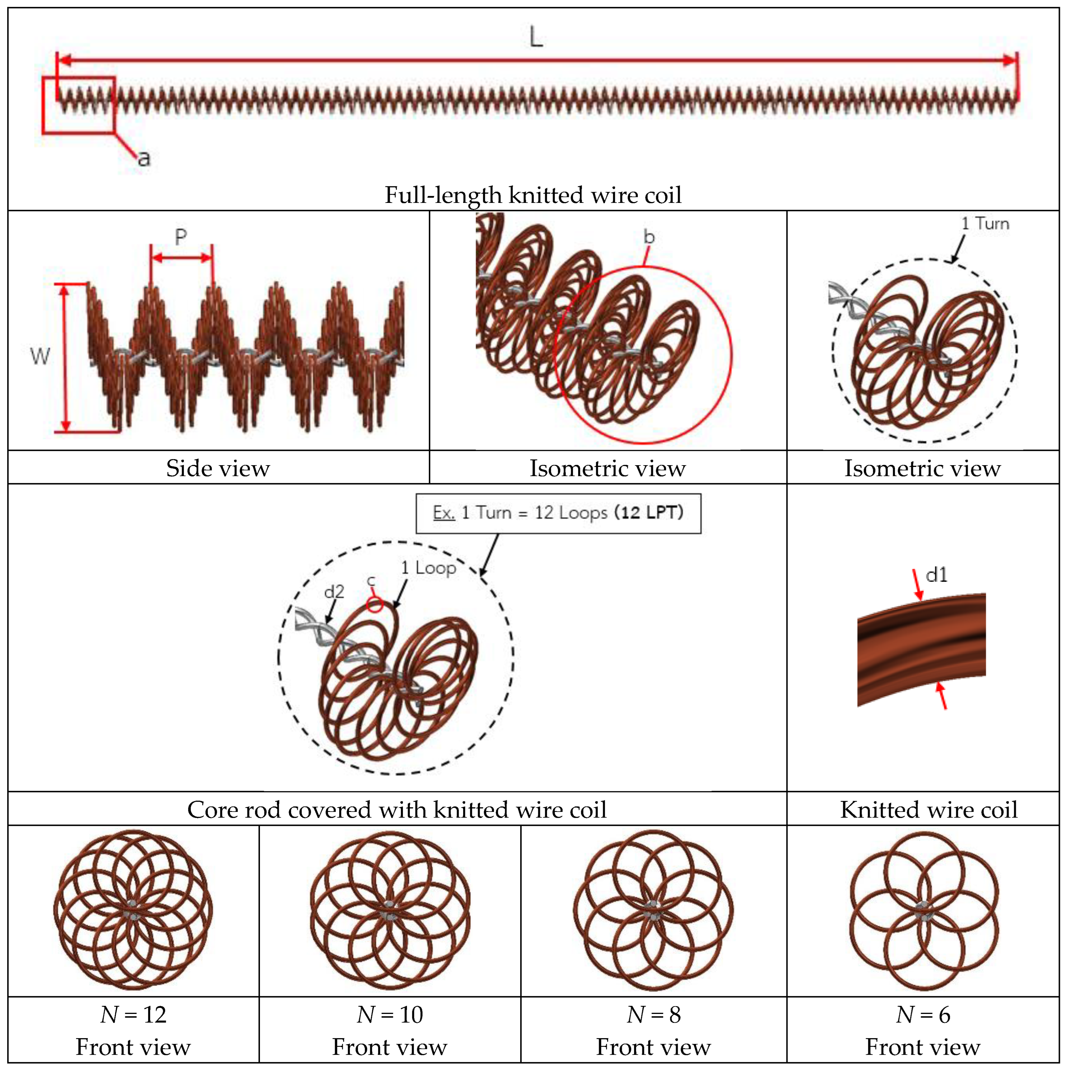
Figure 2. Details of knitted wire coil turbulator geometries.
Eng 06 00337 g002
Figure 3. Images of knitted wire coil turbulators with various numbers of loops per pitch (N = 6, 8, 10, and 12).
Eng 06 00337 g003aEng 06 00337 g003b
Figure 4. Flow visualization setup and facility: water pump, bellmouth entry, digital camera, personal computer, water tank, drain tank, drain pipe, control valve, and bypass valve.
Eng 06 00337 g004
Figure 5. Details of the flow visualization apparatus: (1) inlet pipe, (2) over head pipe, (3) acrylic pipe, (4) outlet pipe, (5) bellmouth entry, (6) glass ball, (7) over flow pipe, (8) dye system, (9) flow meter, (10) control valve and (11) Exit tube.
Eng 06 00337 g005
Figure 6. Details of the dye injection system: (1) dye reservoir, (2) dye flow control valve, and (3) dye injection needle.
Eng 06 00337 g006
Figure 7. Details of the heat transfer apparatus: uniform heat flux tube, cooling tank, water pump, rotameter, T-type thermocouples, RTDs, data logger, controller box, Variac transformer, Watt meter, U-tube manometer and digital pressure manometer, and computer. (a) Heat transfer diagram setup. (b) Photograph of experimental setup. (c) Uniform heat flux tube fitted with thermocouples and a tube with a knitted wire coil turbulators inserted.
Eng 06 00337 g007aEng 06 00337 g007b
Figure 8. Flow pattern in a plain tube with/without a knitted wire coil turbulator using a dye injection technique. (a) Plain tube. (b) Tube fitted with knitted wire coil turbulator, N = 6. (c) Tube fitted with knitted wire coil turbulator, N = 8. (d) Tube fitted with knitted wire coil turbulator, N = 10. (e) Tube fitted with knitted wire coil turbulator, N = 12.
Eng 06 00337 g008aEng 06 00337 g008bEng 06 00337 g008c
Figure 9. Flow pattern in a plain tube with/without a knitted wire coil turbulator using a dye injection technique. Flow pattern in a tube with a knitted wire coil turbulator at various numbers of loops (N).
Eng 06 00337 g009
Figure 10. Flow pattern in a plain tube with a knitted wire coil turbulator at different dye injection locations. (a) X/D = 0.0–1.0; (b) X/D = 1.0–5.0; (c) X/D = 5.0–10.0.
Eng 06 00337 g010
Figure 11. Validation test of the Nusselt number and friction factor of a plain tube.
Eng 06 00337 g011
Figure 12. Effect of knitted wire coil turbulators on the Nusselt number.
Eng 06 00337 g012
Figure 13. Effect of knitted wire coil turbulators on the friction factor.
Eng 06 00337 g013
Figure 14. Effect of knitted wire coil turbulators on the thermal performance index.
Eng 06 00337 g014
Figure 15. Predicted values versus experimental results.
Eng 06 00337 g015aEng 06 00337 g015b
Figure 16. Comparison work with coiled-wire [6], conical ring turbulator [34], and conical braided wire turbulator [35].
Eng 06 00337 g016
Table 1. Summary of previous work.
AuthorsSummary of Experimental Circular Tube Thermal Performance Index (TPI)
Fan et al. [1]Numerical study of a circular tube with conical strip inserts for turbulent flow (Re = 12,000–42,000). Larger slant angles and smaller pitches improved heat transfer but increased resistance, with slant angle having a stronger influence.
Gunes et al. [3]Coiled wire inserts (Re = 4105–26,400). Results showed Nu/Nup = 2.38–3.03, f/fp = 7.13–8.22, and TPI ≈ 1.51. Optimal performance occurred at P/D = 1.0, s = 1.0 mm, Re ≈ 4220, giving ~50% higher efficiency than the smooth tube. Decreasing the pitch ratio and wall gap enhanced both Nusselt number and friction factor
Karakaya and Durmus [4]Conical spring turbulators (CST) at angles of 30°, 45°, and 60° (Re = 10,000–34,000). The inserts enhanced heat transfer and increased pressure drop compared to a smooth tube. Optimal conditions were found at moderate spring angles, where Thermal performance index and exergy efficiency were improved. Conical-shaped springs with a 30° cone angle exhibited the highest heat transfer enhancement.
Keklikcioglu and Ozceyhan [6]Triangular coiled-wire inserts placed 1 mm from the wall (Re = 2851–27,732). The best configuration (e/D = 0.0892, P/D = 1.0) achieved Nu/Nup = 2.12–3.41, f/fp = 4.2–8.8, and TPI ≈ 1.68, showing ~18% higher enhancement than earlier wire designs. The optimal configuration (e/D = 0.089, P/D = 1.0) achieved up to 1.68 times higher thermal performance than a smooth tube.
Nanan et al. [7]Helically twisted tape inserts inducing co- and counter-swirl flows (Re = 6000–20,000). Results showed Nu/Nup = 2.82–3.29, f/fp = 33.2–36.7, and TPI ≈ 1.29. Counter-swirl tapes gave higher heat transfer but lower overall efficiency, while co-swirl tapes provided better thermal performance index at larger pitch ratios. Helically twisted tapes inducing co-swirl flows achieved higher thermal performance factors than counter-swirl tapes, while reducing pitch ratios increased Nusselt number and friction factor but lowered thermal performance.
Akhavan-Behabadi et al. [8]Double-pipe heat exchanger with coiled wire inserts during oil heating (Re based on oil flow). Wire diameters of 2.0 and 3.5 mm with pitches of 12–69 mm were tested. The inserts significantly increased the heat transfer coefficient and friction factor compared to a smooth tube. Empirical correlations for Nu/Nup and f/fp were developed, predicting results within ±20%, with optimal performance at smaller pitch and larger wire diameter. Wire coil inserts with smaller wire diameters demonstrated superior thermal performance, particularly at low Reynolds numbers, while variations in coil pitch had only a minor influence on heat transfer enhancement.
Gunes et al. [10]Triangular coiled-wire inserts placed 1 mm from the wall (Re = 3500–27,000). Results showed Nu/Nup = 2.12–3.41 and f/fp = 4.2–8.8. The best performance occurred at a/D = 0.0892, P/D = 1, Re ≈ 3858, with ~36.5% overall enhancement, especially effective at low Reynolds numbers for compact heat exchanger design. Increasing wire thickness and decreasing pitch ratio improved heat transfer, with the highest overall enhancement efficiency of 36.5% achieved at a/D = 0.0892 and P/D = 1.0 for a Reynolds number of 3858
Hong et al. [11]Wire coil (WC) inserts of uniform, varying pitch, and gradually varying width (Re = 6000–20,000). Heat transfer was enhanced with Nu/Nup = 1.46–2.49 and friction factor increased to f/fp = 8.36–18.62. The highest TPI ≈ 1.14 was achieved for uniform pitch WCs at p/d = 1.034, while varying pitch and width provided no further efficiency improvement despite higher Nu.
Nanan et al. [21]Wire-rod bundle turbulators (Re = 6000–20,000). Results showed Nu/Nup = 1.04–1.69 and f/fp = 2.56–4.53, depending on rod number and pitch ratio. The TPI ≈ 1.02 was achieved at high rod numbers with low pitch ratios, indicating minor efficiency gains but consistent enhancement trends. Increasing the number of wires and reducing the pitch ratio improved the Nusselt number and thermal performance.
Naphon and Suchana [22]Concentric tube heat exchanger with twisted wire brush inserts (Re = 6000–20,000). Increasing brush density (100–300 wires/cm) enhanced heat transfer but also caused significant pressure loss. Compared to the plain tube, heat transfer rose markedly (Nu/Nup > 1) while friction increased substantially, with no optimal TPI beyond unity due to high flow resistance. Increasing the density of full-length twisted wires enhanced heat transfer and Nusselt number, with the 300-wire insert giving the best results.
Bhuiya et al. [23]Twisted wire brush inserts (Re = 7200–50,200). Heat transfer and friction were significantly enhanced, with Nu/Nup ≈ 2.15 and f/fp ≈ 2.0 over the plain tube. The TPI ≈ 1.85 was obtained at higher wire densities, confirming strong thermo-hydraulic improvement under constant blower power.
Chompookham et al. [27]Serrated wire coil (SWC) inserts combining coiled wire and V-shaped ribs (Re = 5114–14,752). Heat transfer increased with decreasing pitch and larger coil diameter, giving Nu/Nup = 1.75–2.46 and f/fp = 3.31–8.16. The maximum TPI ≈ 1.41 was achieved at DC = 47.9 mm, PC = 10 mm, Re = 5114, confirming SWC as a more effective turbulator than conventional coils. Smaller pitch lengths and larger coil diameters improved heat transfer enhancement.
Hashemian et al. [29]Helically coiled tubes with helical wire inserts under single-phase (water) and two-phase (air–water) flow. Water flow rates of 2–8 L/min and air flow rates of 1.0–5.0 L/min were tested (VF = 0.11–0.714). Results showed enhanced heat transfer but increased pressure drop, with exergy efficiency reduced by up to 87% when inserts were used in single-phase flow. Optimal use was suggested for two-phase flow with turbulator where heat transfer improvement outweighs friction losses. For single-phase flow, exergy efficiency is higher without a turbulator.
Hong et al. [30]Traverse corrugated tubes (TCTs) with twin and triple wire coil (WC) inserts (Re = 6000–18,000). Heat transfer rose with coil number and reduced spacing, giving Nu/Nup = 1.74–2.61 and f/fp = 4.57–21.34. The maximum TPI ≈ 1.09 was found for twin WCs at S/D = 18.1, while the TCT alone reached TPI ≈ 1.26. Entropy analysis showed reduced Bejan number, with the lowest augmented entropy generation at triple WCs, S/D = 0.0, Re ≈ 6428. Heat transfer improved with more coils and smaller spacing, though the best overall performance occurred with twin WCs at the largest spacing
Table 2. Details of knitted wire coil turbulator geometries.
ListValueUnit
Cross-sectional diameter (D)17.5mm
Length of knitted wire coil (L)650mm
Pitch of knitted wire coil (P)6.8mm
Pitch ratio (P/D)0.9-
Diameter of wire (d1)0.7mm
Diameter of core rod (d2)1.0mm
Number of loops per pitch (N)6, 8, 10, and 12-
Table 3. Details of the test section.
ListValueUnit
Test section length650mm
Overall test section length1700mm
Entry length700mm
Exit length350mm
Inner diameter of test tube (Di)17.5mm
Thickness of test tube (δ)1.0mm
MaterialCopper
Table 4. Experimental uncertainties.
VariableUncertainties (%)
Air flow velocity, U±2.98
Air viscosity, µ±0.07
Pressure, P±4.1
Ammeter, I±2.2
Air temperature, T±0.14
Thermal conductivity, k±0.37
Voltmeter, V±0.97
Disclaimer/Publisher’s Note: The statements, opinions and data contained in all publications are solely those of the individual author(s) and contributor(s) and not of MDPI and/or the editor(s). MDPI and/or the editor(s) disclaim responsibility for any injury to people or property resulting from any ideas, methods, instructions or products referred to in the content.