Article

Development of a Methodology for Seismic Design of Framed Steel Structures Incorporating Viscous Dampers

by
Panagiotis Diamantis
1,
Panagiota Katsimpini
1,2,* and
George D. Hatzigeorgiou
2
1
Department of Civil Engineering, School of Engineering, University of the Peloponnese, GR-26334 Patras, Greece
2
School of Science and Technology, Hellenic Open University, GR-26335 Patras, Greece
*
Author to whom correspondence should be addressed.
Eng 2025, 6(11), 308; https://doi.org/10.3390/eng6110308
Submission received: 11 September 2025 / Revised: 26 October 2025 / Accepted: 29 October 2025 / Published: 4 November 2025
(This article belongs to the Section Chemical, Civil and Environmental Engineering)

Abstract

This study develops empirical equations relating viscous damping ratios (ξ) and damper coefficients (c) in steel structures for seismic design applications. The objective is to establish predictive formulas that enable conversion between equivalent viscous damping ratios and physical damper characteristics through dynamic analysis. This research employs a two-phase analytical methodology on steel building frameworks. Initially, inherent viscous damping ratios are incrementally varied from 3% to 40% to establish baseline response characteristics. Subsequently, supplemental damping devices are integrated with damper coefficients (c) adjusted according to manufacturer specifications. Linear time-history analyses are conducted for both configurations to determine equivalent damping relationships, with a particular focus on Interstory Drift Ratios (IDR) and Peak Floor Accelerations (PFA) as key seismic demand parameters. By comparing response quantities between inherent and supplemental damping scenarios, empirical relationships linking physical damper coefficients with equivalent viscous damping ratios are formulated. The resulting equations provide practicing engineers with a practical tool for estimating damper specifications based on target damping levels in steel structures. The formulations are derived from linear time-history analysis of steel frame configurations and are applicable within the scope of linear elastic response and viscous damper behavior consistent with typical design conditions.

1. Introduction

Throughout the last decade, extensive research initiatives and investigations have focused on passive damping technologies that use dampers. These studies have shown promising results for controlling and reducing the response of steel structures during earthquakes. Multiple investigations [1,2,3,4,5,6,7] have examined various systems and mechanisms using both viscous dampers and linear as well as non-linear configurations. The concept of additional damping is based on energy dissipation principles [8,9,10,11,12]. During earthquakes, ground movements transfer kinetic energy to buildings, which must be absorbed or dissipated to prevent damage or collapse. Traditionally, seismic design has relied on the inherent damping characteristics of building materials and the ductile response of structural components to manage this energy.
The potential of additional damping technologies extends beyond improving structural safety; they also help lower building costs, and since the requirement for post-earthquake restoration is significant they help enhancing the overall durability of urban regions [13,14,15,16,17,18]. Recent innovations in materials engineering, control systems, and computational methodologies have facilitated the development of more refined damping mechanisms. [19,20,21]. In 2015, Silwal et al. [22] introduced a hybrid passive control mechanism and assessed its effectiveness in improving the response of steel frames under various seismic hazard intensities. The superelastic viscous damper (SVD) they developed includes shape memory alloy (SMA) cables for self-centering capability and a viscoelastic (VE) damper made of two layers of butyl-based high damping elastomeric material to enhance energy dissipation performance.
Selecting and sizing damping mechanisms is crucial for integrating additional damping systems into the seismic design of structures. Lavan and Amir [23] illustrated that engineers need to assess various factors, such as the dynamic characteristics of a structure, anticipated seismic loads, and desired performance objectives. Güllü et al. [24] pointed out that the selection of damper type—be it viscous, viscoelastic, or friction-based—relies on its attributes and compatibility with structural requirements. Furthermore, research conducted by Nabid et al. [25] indicated that the quantity, dimensions, and positioning of dampers within the structure are vital for optimizing their effectiveness in mitigating seismic responses. Wang and Mahin [26] stressed that the sizing approach must take into account practical limitations such as installation space constraints, architectural specifications, and maintenance accessibility. Their study highlights the significance of these practical factors in the design process.
Recently, the pace of development for innovative seismic protection mechanisms has increased, particularly in relation to the seesaw system, recognized for its exceptional approach to controlling structural responses [27,28,29,30,31]. The seesaw mechanism incorporates a central pivot point that balances the structure [30,31,32]. The effectiveness of the seesaw system has been substantiated through numerical modeling and experimental investigations, confirming its applicability for both new construction and the rehabilitation of existing structures [32].
Mo et al. [33] introduced a novel type of air spring-lead rubber bearing (AS-LRB) three-dimensional seismic isolation device that provides both horizontal and vertical seismic isolation. The findings indicate that the air spring (AS) within the AS-LRB is responsible for vertical seismic isolation, while the lead rubber bearing (LRB) is tasked with horizontal seismic isolation. Mo et al. [34] note that the stacked modular steel building (SMSB) is extensively utilized in China due to its quick assembly, cost efficiency, and environmental advantages. The seismic isolation technology, especially the air spring-lead rubber bearing (AS-LRB) developed by the Mo et al. [34], presents a viable solution to improve the resilience of SMSB.
In their 2016 research, Banazadeh and Ghanbaru [35] conducted a comparative analysis of the seismic performance during the collapse of steel moment-resisting frames (MRFs) with identical additional damping ratios while equipped with linear and non-linear viscous dampers. They determined the properties of linear (α = 1) and nonlinear (α = 0.5) dampers, assuming equivalent damping ratios (20% for 6 and 8-story models and 25% for the 12-story model).
Hatzigeorgiou’s investigation [36] presents a simple and effective method for calculating DMF in single-degree-of-freedom systems. The study recommends empirical equations for displacement, velocity, and acceleration response spectra, considering four different soil conditions from hard rock to soft soil. It confirms that, contrary to many seismic code assumptions, DMF is significantly influenced by the structural vibration period, and there are significant challenges in applying the same modification factor to estimate maximum displacement, velocity, and seismic forces.
Hatzigeorgiou and Pnevmatikos [37] studied the inelastic response behavior of structures with supplemental viscous dampers under near-source pulse-like ground movements. It is well understood that damper design requires thorough evaluation of maximum seismic velocities or maximum damping forces. To simplify methods like dynamic inelastic analysis, this study presents a straightforward and effective method for evaluating these maximum values using the inelastic velocity ratio. This ratio acts as a modification factor that allows for the assessment of maximum inelastic velocity or damping force based on their elastic counterparts.
Logotheti et al. [38] developed a basic equation to calculate inter-storey velocities of steel-framed structures at specific inter-storey drift levels. The proposed formula is statistically derived from variations in floor relative velocity results along the height of the structure. These results come from non-linear inelastic time history analyses conducted on multiple planar steel moment-resisting frames. The proposed equation can be used in seismic retrofitting, especially for sizing linear or non-linear viscous dampers to be installed in steel frames. They provide a detailed numerical example and conclusions regarding the accuracy and potential uses of inter-storey velocity.
Mavroeidakos et al. [39] examined the seismic performance of steel structures equipped with both linear and nonlinear viscous dampers that may have variable capacity. Specifically, nonlinear time history analyses were performed on two three-dimensional steel buildings using several recorded seismic motions. Initially, they assumed a uniform distribution of viscous dampers throughout the building height and determined the damping coefficients for sizing the dampers. They then conducted nonlinear time history analyses assuming either linear or non-linear viscous dampers operating at 80%, 100%, and 120% of their capacity.
In terms of cost-effectiveness, Kolour et al. [40] proposed a life-cycle optimization strategy that reconciles initial costs with long-term advantages. This strategy encompasses the development of probabilistic cost–benefit models that consider regional seismic hazard levels and the integration of sustainability metrics into the decision-making process. Moreover, recent developments in artificial intelligence and machine learning have resulted in groundbreaking solutions for optimizing damper design. Gharagoz et al. [41] illustrated the use of deep learning algorithms for a real-time modification in damper properties based on structural response data.
To address challenges related to code compliance, Wen et al. [42] introduced a performance-based design framework that connects various international standards. Their approach includes the creation of project-specific acceptance criteria that fulfill multiple code requirements, as well as the implementation of hybrid testing protocols that cater to both component and system-level performance.
The optimization of damper placement and sizing has been extensively studied through various methodologies. Takewaki [43] presented comprehensive procedures for optimal selection and placement of passive control systems, combining theoretical frameworks with practical applications. Aydin et al. [44] investigated optimal damper placement using transfer function approaches, demonstrating that base shear force minimization can be an effective objective function for seismic rehabilitation. Lavan [45] developed a continuum approach for viscously coupled shear walls, revealing that system damping ratio serves as a convenient parameter controlling response reduction across different building heights. Palermo et al. [46] proposed a direct procedure for determining damper characteristics capable of providing prescribed damping ratios in moment-resisting frames. Recent advances in design methodologies have also emphasized the importance of ensuring global collapse mechanisms to maximize energy dissipation capacity, as demonstrated by Montuori and Muscati [47,48] through the Theory of Plastic Mechanism Control, which prevents undesired failure modes such as soft-story mechanisms.
Recent advancements in viscous damper technology have further expanded their application in seismic protection of steel structures. Numerous studies have demonstrated significant progress in damper design optimization [49,50,51,52], smart damping systems with adaptive capabilities [53,54,55,56,57,58], and novel installation strategies [59,60,61] that enhance both effectiveness and constructability. These recent developments emphasize the growing importance of supplemental damping as a mainstream seismic protection strategy, particularly for urban structures where performance-based design criteria demand reliable control of both drift and acceleration responses [62,63]. Contemporary research has also focused on life-cycle performance assessment of damper-equipped structures, considering not only initial seismic resistance but also long-term durability and maintenance requirements [64,65,66,67,68,69].
Figure 1 depicts the comprehensive framework of seismic protection strategies, highlighting the significance of supplementary damping systems in the broader context of structural control techniques [70].
Despite the extensive research on viscous damping systems and the demonstrated effectiveness of various optimization methodologies, a critical gap remains in current design practice: the lack of readily applicable, closed-form relationships that directly connect damping characteristics to structural response parameters without requiring iterative computational procedures. Existing approaches, whether based on energy dissipation principles, optimization algorithms, or performance-based frameworks, typically necessitate complex trial-and-error processes involving repeated nonlinear time-history analyses to achieve target performance levels. This computational burden poses significant challenges for practicing engineers, particularly during preliminary design stages or when rapid seismic assessment of existing structures is required. Furthermore, while numerous studies have investigated optimal damper placement and sizing strategies, the majority focus on specific case studies or require sophisticated optimization routines that may not be easily transferable across different structural configurations.
The present study addresses this knowledge gap by developing empirical equations derived from a comprehensive parametric investigation of numerous analytical cases, providing engineers with practical design tools that enable direct prediction of required damping coefficients based on specified performance criteria for steel frame buildings, thereby eliminating the need for iterative computational cycles during the preliminary design phase. More specifically, aim of this paper is to create relationships between viscous damping characteristics and structural response parameters for both 3-story and six-story steel frame buildings. By examining 1190 analytical cases with various damping configurations and seismic loading scenarios, a comprehensive database is built that aids in predicting crucial structural response quantities like inter-story drift ratios, peak floor accelerations, and top floor displacements. These results emphasize the need for further research to integrate additional parameters, including natural frequency characteristics and higher-order dynamic effects, to refine the accuracy of our proposed formulations. Still, the methodology that was developed and the empirical relationships have been established provide a robust foundation for future studies and practical design tools for engineers involved in seismic retrofitting and the implementation of passive damping systems.
The main contribution of this paper is the creation of thorough empirical relationships that directly link viscous damping characteristics to structural response parameters in steel frame buildings. Unlike current methods that necessitate iterative computational processes, this study offers closed-form equations that allow engineers to forecast damping coefficients and their efficacy according to specified performance criteria. This marks a notable progress in practical seismic design methodology by removing the requirement for intricate trial-and-error damper sizing techniques.

2. Description of Structures

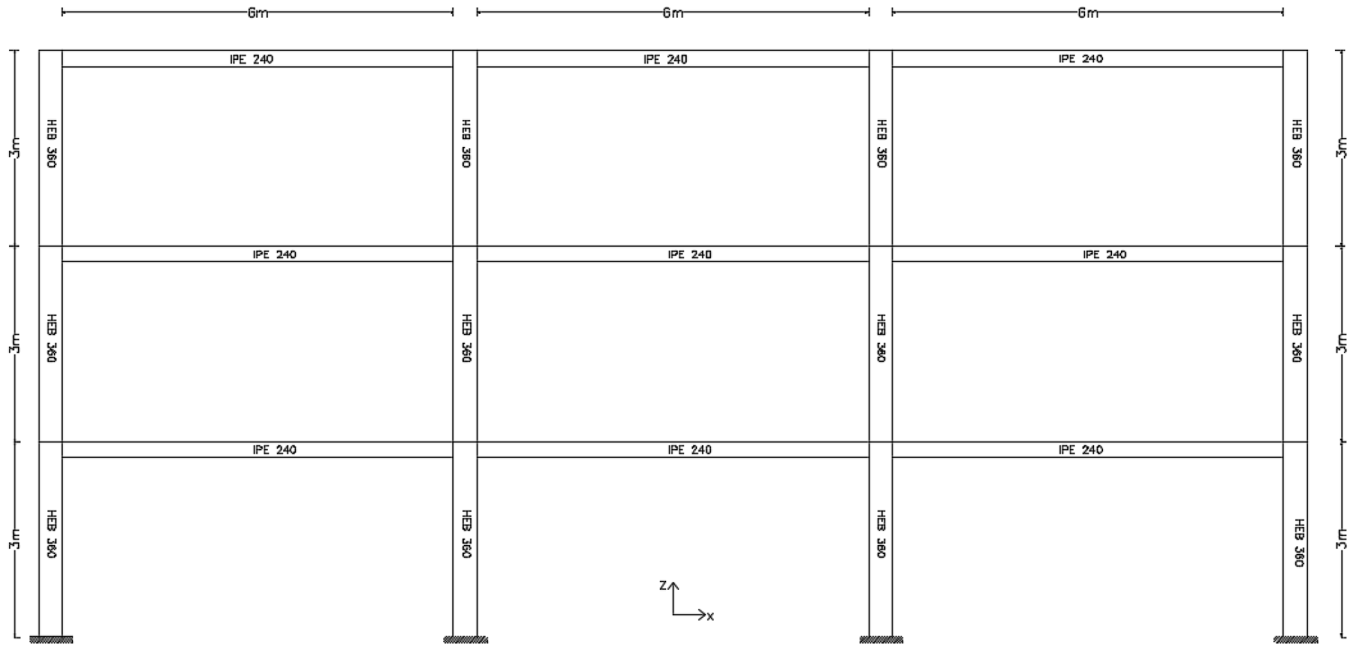
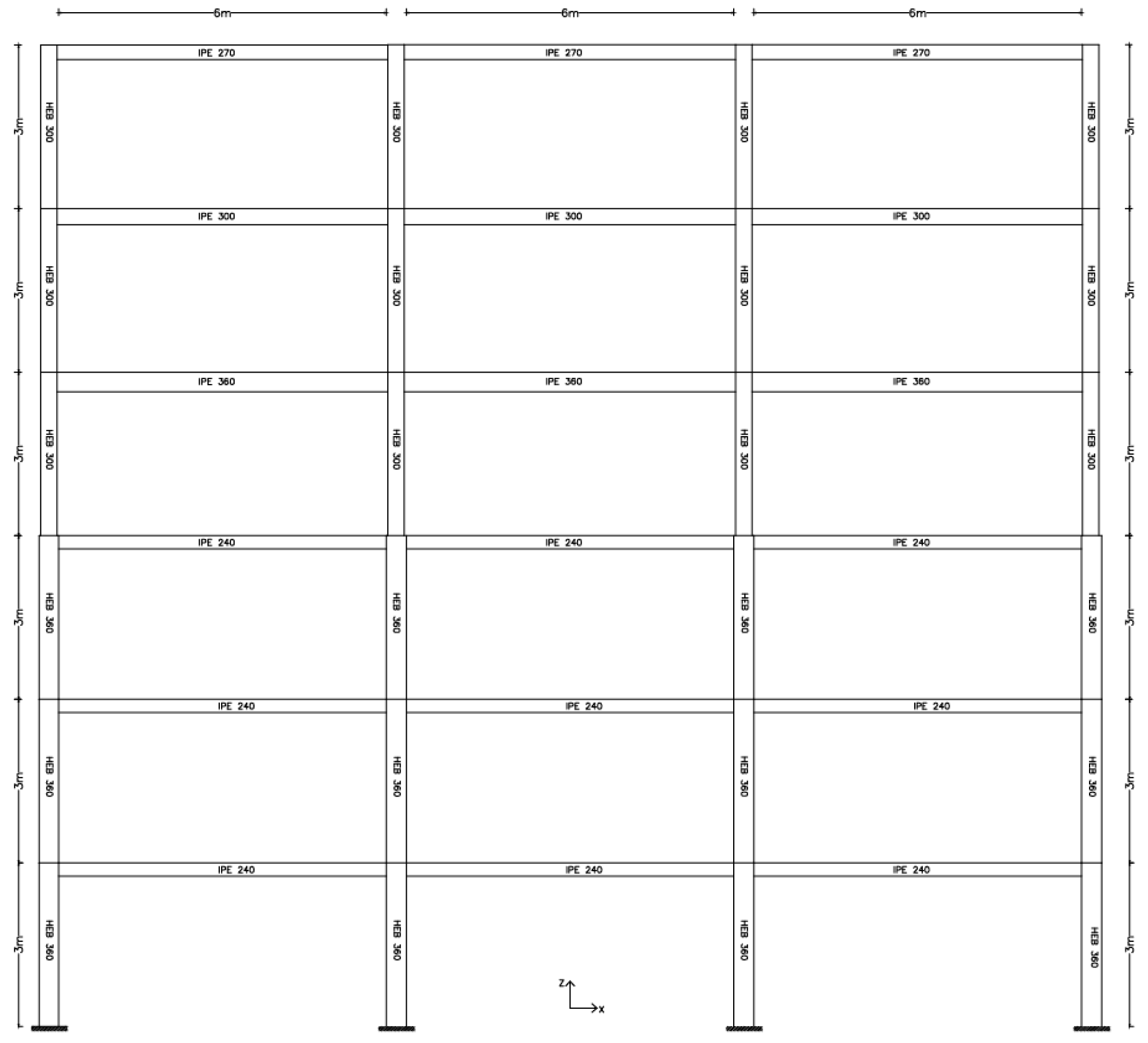
For the analyses, the software SAP2000 [71] was used following the procedure below. Initially, two building models were created: one three-story (Figure 2) and one six-story (Figure 3), composed of steel strength sections (S275), each consisting of three horizontal bays of 6 m and floor height of 3 m. The six-story building was designed sectionally per two floors: the first two use IPE360 beams, the next two IPE300, and the top two IPE270. Columns differ per three floors, with the lower ones using HE360B and the top three using HE300B sections. The three-story building did not require much variation in sections; so, identical columns and beams were used throughout, composed entirely of HE360B columns and IPE240 beams. The details are shown below (Table 1).
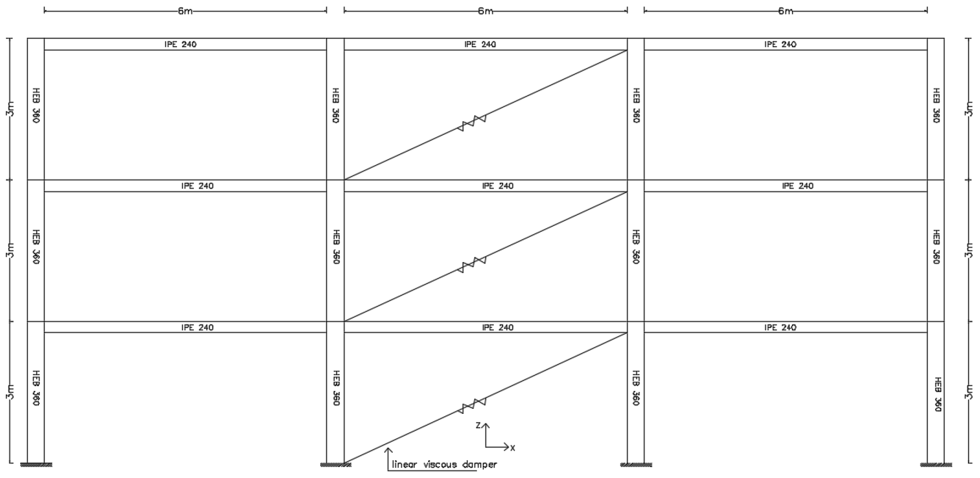
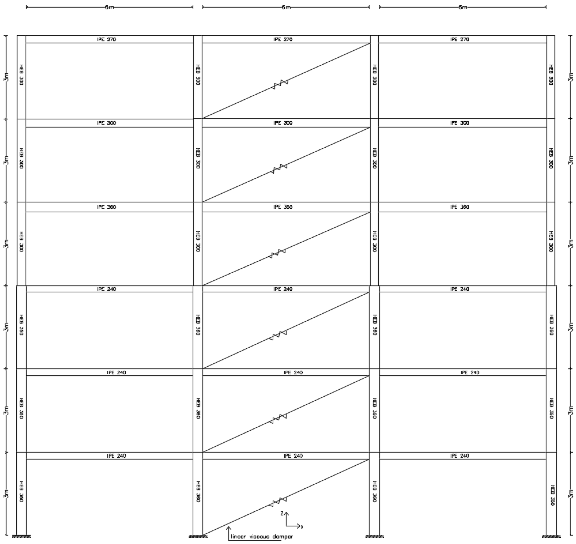
In the current research, it was assumed that the damping coefficient stays constant across all levels of the building (Figure 4 and Figure 5). For the parametric analysis aimed at examining how damping affects the building’s dynamic response, a total of eleven distinct values of the damping coefficient were analyzed. The values considered were 250, 500, 750, 1000, 1500, 2000, 2550, 3000, 4000, 6500, and 8000 kN·s/m. These values were chosen to explore a wide range of damping conditions, from low to high levels, to evaluate the impact of the damping coefficient on the system’s overall behavior. Assuming a uniform distribution of the damping coefficient across all floors simplifies the evaluation of this parameter’s effect, avoiding the complications of varying damping values on each floor. This approach allows for a clear investigation of how different levels of structural damping affect the building’s seismic response characteristics.
The viscous dampers were installed in a diagonal configuration within the central bay of each floor. Specifically, one damper was placed per floor, oriented diagonally to connect the corner nodes of the middle bay. This diagonal arrangement is effective for capturing interstory drift velocities and maximizing energy dissipation during lateral seismic response. For the three-story structure, this resulted in three dampers (one per floor), while the six-story structure was equipped with six dampers (one per floor). The dampers were connected at beam-column joints using rigid link elements to ensure proper force transfer. This uniform distribution pattern, with dampers consistently placed in the central bay across all floors as illustrated in Figure 4 and Figure 5, was maintained throughout all parametric analyses to isolate the effect of damping coefficient variations on structural response without introducing complexities from non-uniform damper placement strategies.
The live load was assessed to be equivalent to 2 kN/m2, whereas the superimposed dead load was determined to be 1.5 kN/m2. The structural design complies with the guidelines established by Eurocode 3 [72], guaranteeing their durability against seismic forces as outlined by the design spectrum of EC8 [73]. The parameters consist of a peak ground acceleration (PGA) of 0.24 g, soil class B, an importance factor γ of 1.0, and a behaviour factor q of 4.
For the purposes of this parametric study, linear elastic material behavior was assumed for all structural members throughout the analyses. This assumption is appropriate given that linear time-history analyses were employed to establish the fundamental relationships between damping parameters and structural response. The elastic modulus for S275 steel was taken as 210 GPa with a Poisson’s ratio of 0.3, following standard material properties. While the Introduction emphasizes the importance of ductile response and energy dissipation in seismic design, the focus of this research is on the contribution of supplemental viscous dampers to overall damping capacity rather than on inelastic material behavior. The linear elastic assumption allows for clearer isolation of damping effects and facilitates the development of predictable relationships between damping coefficients and response parameters. For practical design applications where structures may experience inelastic deformations, the derived equations provide conservative estimates of damping effectiveness and can serve as initial sizing tools for viscous damper systems.
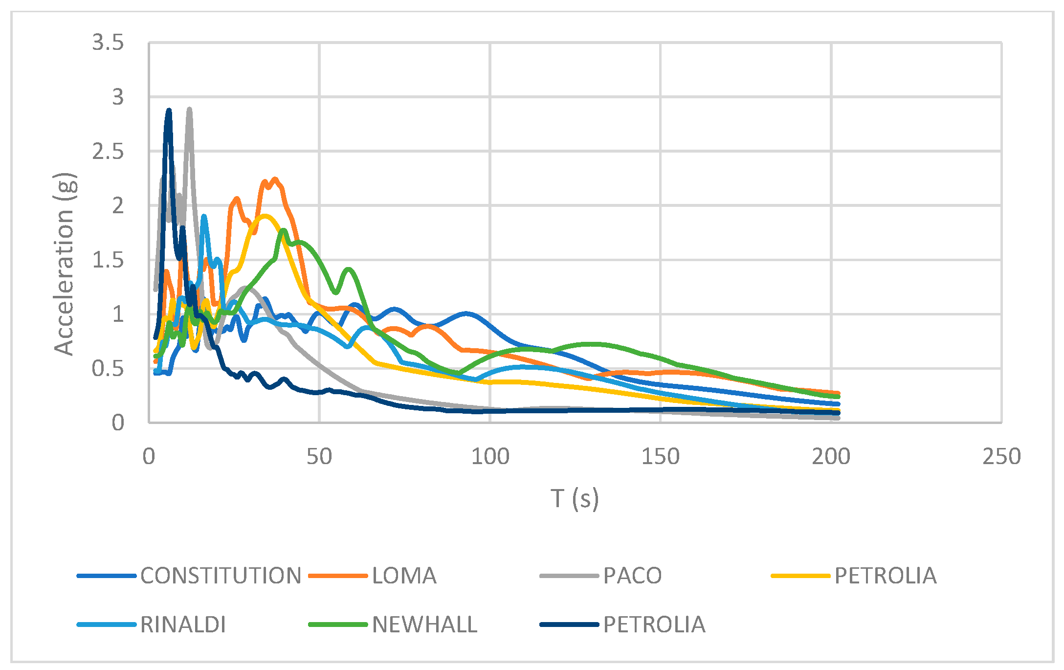
The three-storey and six-storey buildings illustrated in the figure are influenced by the horizontal components of the 7 accelerograms provided in Table 2, according to data sourced from the PEER database [74]. The chosen earthquake ground motions exhibit a wide range of diversity across several key parameters that are vital for thorough structural analysis. Magnitude Range Diversity guarantees representation from moderate to extremely large seismic events, with earthquakes ranging from magnitudes of 6.3 (Christchurch, New Zealand) to 8.8 (Maule, Chile), thereby encompassing the entire spectrum of ground motion intensities that structures may face throughout their operational lifespan. Soil Condition Variety includes the three main site classifications that greatly affect ground motion characteristics: Hard Rock conditions illustrated by the Loma Prieta and San Fernando events, Soft Rock conditions derived from the Maule and Cape Mendocino earthquakes, and Stiff Soil conditions from both Northridge events and Christchurch, ensuring that the analysis considers site amplification effects and soil-structure interaction phenomena. Geographic and Tectonic Diversity is realized through motions sourced from various seismic regions such as California, Chile, and New Zealand, reflecting different tectonic environments and fault mechanisms that yield unique ground motion characteristics in terms of duration, frequency content, and directivity effects. The selection comprises Well-Documented Events—all significant earthquakes that have been meticulously recorded in the PEER database, featuring high-quality accelerogram data and dependable metadata, thus ensuring analytical reliability and reproducibility. Near-Field and Far-Field Effects are represented through recordings taken at varying distances from fault ruptures, capturing different frequency content and pulse characteristics that can significantly influence structural response, especially for buildings with diverse dynamic properties. Lastly, Frequency Content Variation across different earthquakes and soil conditions offers essential diversity for the analysis of buildings with differing fundamental periods, ensuring that both three-storey and six-storey structures are exposed to ground motions capable of exciting their respective dynamic characteristics.
There is no application of amplitude scaling or spectral matching techniques to the seismic motions. The response spectrum of seismic motions is presented in Figure 6.

3. Modelling of Viscous Dampers

Viscous dampers operate based on fluid dynamics principles. They usually consist of a piston that moves through a cylinder filled with a thick fluid, typically a silicone-based compound. As the piston moves, it forces the fluid through orifices, generating a resistance force that dissipates energy. The relationship between force and velocity for a viscous damper is generally defined as [36]:
F = C·va
where F is the damping force (kN, v = Velocity (m/s), c = Damping coefficient (kN·s/m), a = 0.3–1.0 velocity exponent.
In this study, linear viscous dampers with velocity exponent a = 1.0 were employed exclusively. Thus, Equation (1) becomes
F = c·v
This choice was made for several reasons. Firstly, linear dampers provide a well-established baseline for developing fundamental relationships between damping coefficients and structural response parameters, as their force-velocity relationship is mathematically tractable and allows for a clearer interpretation of the parametric trends. Furthermore, linear viscous dampers are widely implemented in building applications and their behavior is well-documented in manufacturer specifications, making the resulting empirical equations directly applicable to common engineering practice. Additionally, establishing these foundational relationships for linear dampers creates a reference framework that can inform future extensions to nonlinear configurations. While nonlinear dampers (with a < 1.0) offer certain advantages in specific applications, such as reduced forces at high velocities, their inclusion would have significantly expanded the parametric space and complicated the initial development of predictive formulas. The extension of this methodology to encompass nonlinear viscous dampers with various velocity exponents represents a valuable direction for future research, which would build upon the fundamental relationships established herein. The linear viscous dampers were modeled in SAP2000 [71] as link elements that show linear viscous characteristics to model their energy dissipation abilities. These link elements were arranged within the structural framework to reflect the actual position and orientation of the damping devices in the building system. Each damper was assigned linear viscous damping coefficients based on manufacturer guidelines and experimental results. This setup allowed for an accurate depiction of the velocity-dependent force-displacement relationship. The damping characteristics were established through the program’s material property interface, where the viscous damping constant was defined to capture the energy dissipation potential of each device under dynamic loading conditions.
The seismic response of the damped structure to earthquake excitation was then evaluated using a linear time-history analysis. A set of ground motion recordings selected to reflect the seismic risk at the site were used in this analysis, and each record was suitably scaled to fit the design response spectrum. The time-history analysis provided comprehensive insights into the effectiveness of the damping system in reducing structural response and enhancing overall seismic performance by allowing for the direct calculation of structural response parameters such as displacements, velocities, accelerations, and internal forces throughout the seismic excitation period.

4. Results

The research methodology employs a two-phase analytical approach applied to steel building frameworks. In the preliminary phase, the inherent viscous damping ratio is methodically elevated from 3% to 40% in incremental steps to create baseline response characteristics across the entire range of possible damping scenarios. This systematic adjustment allows for an extensive mapping of the relationship between damping levels and structural response. After this, in the second phase, additional damping devices are integrated into the structural system, with damper coefficients (c) tailored according to manufacturer specifications and design parameters [75]. Linear time-history analyses are performed for both configurations to ascertain the equivalent damping relationships. The evaluation of dynamic response concentrates on critical seismic demand parameters, particularly Interstory Drift Ratios (IDR) and Peak Floor Accelerations (PFA), which act as the primary metrics for correlation development.
By comparing response quantities between the inherent damping scenarios and the supplemental damping configurations, empirical relationships are established to link physical damper coefficients with equivalent viscous damping ratios. The formulated equations offer a practical resource for seismic design engineers to ascertain suitable damper specifications based on target damping levels, thereby aiding in the optimization of supplemental damping systems in steel structures. The correlation relationships illustrate the practicality of converting theoretical damping requirements into applicable damper design parameters, enhancing the efficiency and reliability of seismic protection strategies for steel buildings.
Initially, the diagrams needed to be converted into analytical formulas, to be compared and used to develop the desired new relationships. For this, Microsoft Excel [76] was used, where the same diagrams were generated and appropriate trendlines were added to each curve of every diagram. The equations of these curves were given by the software. Once all formulas were gathered, they had to be then condensed into generalized forms that apply across all cases. In total, 385 formulas from the diagrams were condensed into 46 formulas (16 for the 3-story building and 31 for the 6-story) using the method of average values. These equations are presented on Table 3.
The condensation of the 385 formulas into 46 generalized equations was performed using arithmetic averaging of the corresponding trendline coefficients. Specifically, for each structural response parameter (IDR, PFA, or displacement) at each floor level, the regression coefficients obtained from the seven individual seismic records were averaged to produce a single representative equation. This approach assumes that the average response across the selected ground motion suite provides a reasonable estimate of expected seismic demand. To validate this condensation process, the generalized equations were compared against the original analytical results, and the prediction accuracy was assessed. As demonstrated in the next Section 4, through comparisons with established methods from the literature, the generalized equations maintain acceptable accuracy levels. This validates the reliability of the averaging procedure for the parametric ranges considered in this study.
The three-story structure’s top joint’s displacement response, which is impacted by the viscous damping ratio, emphasizes how important energy dissipation mechanisms are to the dynamic behavior of structures. The structural response to dynamic loading conditions is effectively reduced by improved damping capacity, as shown in Figure 7, where an increase in the damping ratio causes a gradual decrease in peak displacement amplitudes. In seismic design applications, where ideal damping ratios can significantly reduce inter-story drifts and absolute accelerations, improving structural safety margins and serviceability performance, this correlation is particularly important. The observed trend supports the fundamental idea that reducing structural vulnerability to ground motions caused by earthquakes can be achieved through controlled energy dissipation through viscous damping mechanisms.
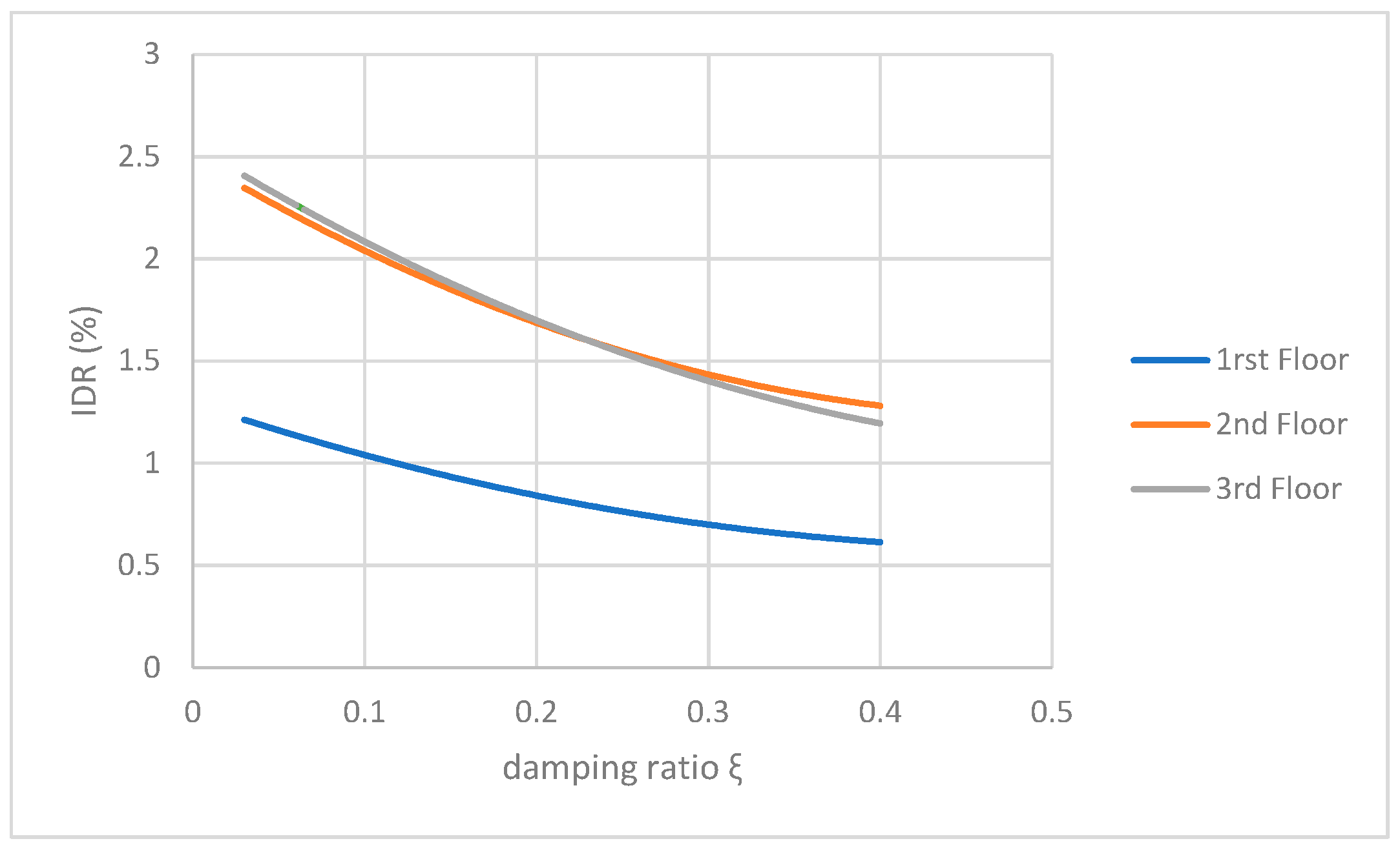
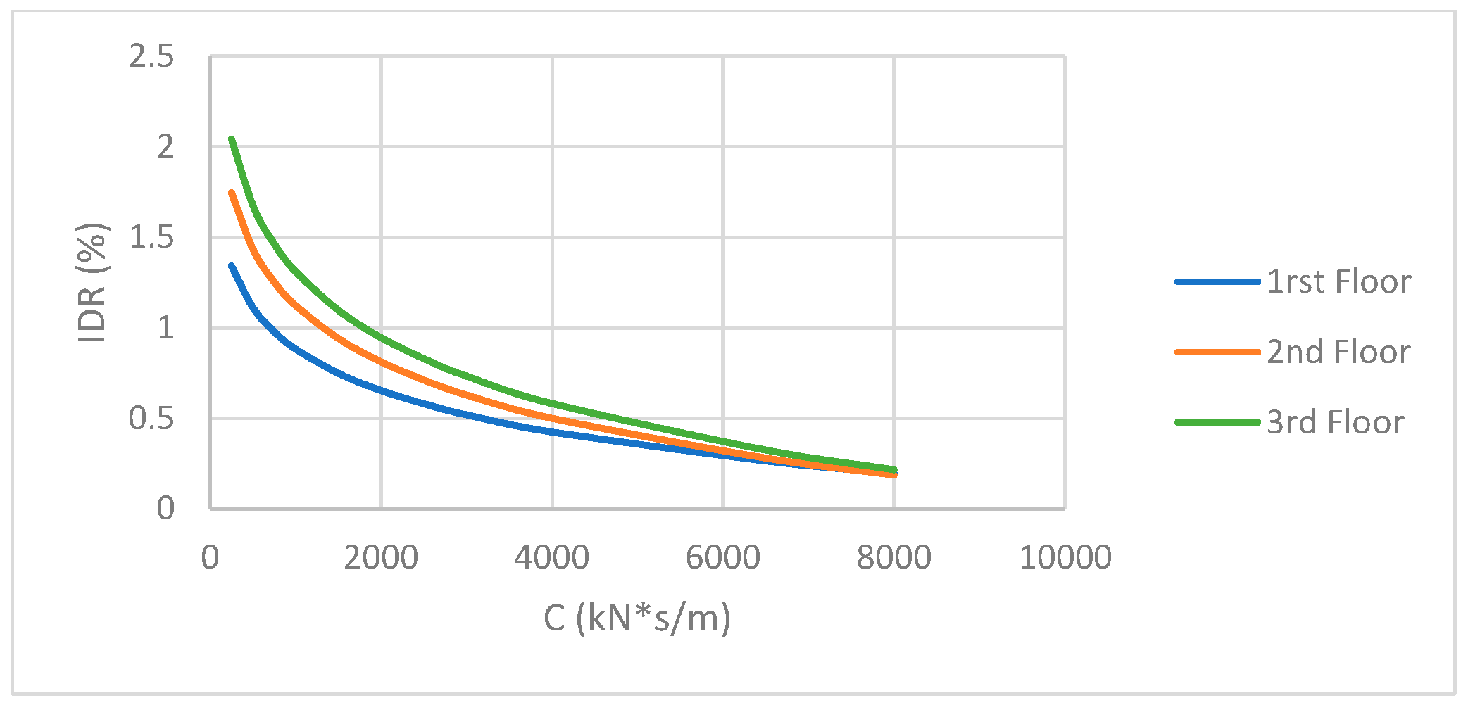
A comparison of Figure 8 and Figure 9 reveals clear relationships between the three-story building’s inter-story drift ratio (IDR) and two different damping parameters. While Figure 9 shows the impact of absolute damping coefficient c-values on the same structural parameter, Figure 8 shows the effect of varying the dimensionless damping ratio, showing how normalized damping characteristics affect drift response. The main difference between these representations is their parametric approach: the damping coefficient gives direct information about the true amount of damping force required for a given drift control, while the damping ratio offers a normalized metric that facilitates comparison across different structural systems and frequencies. Similar patterns of decreased IDR with increased damping are seen in both figures; however, the damping coefficient relationship.
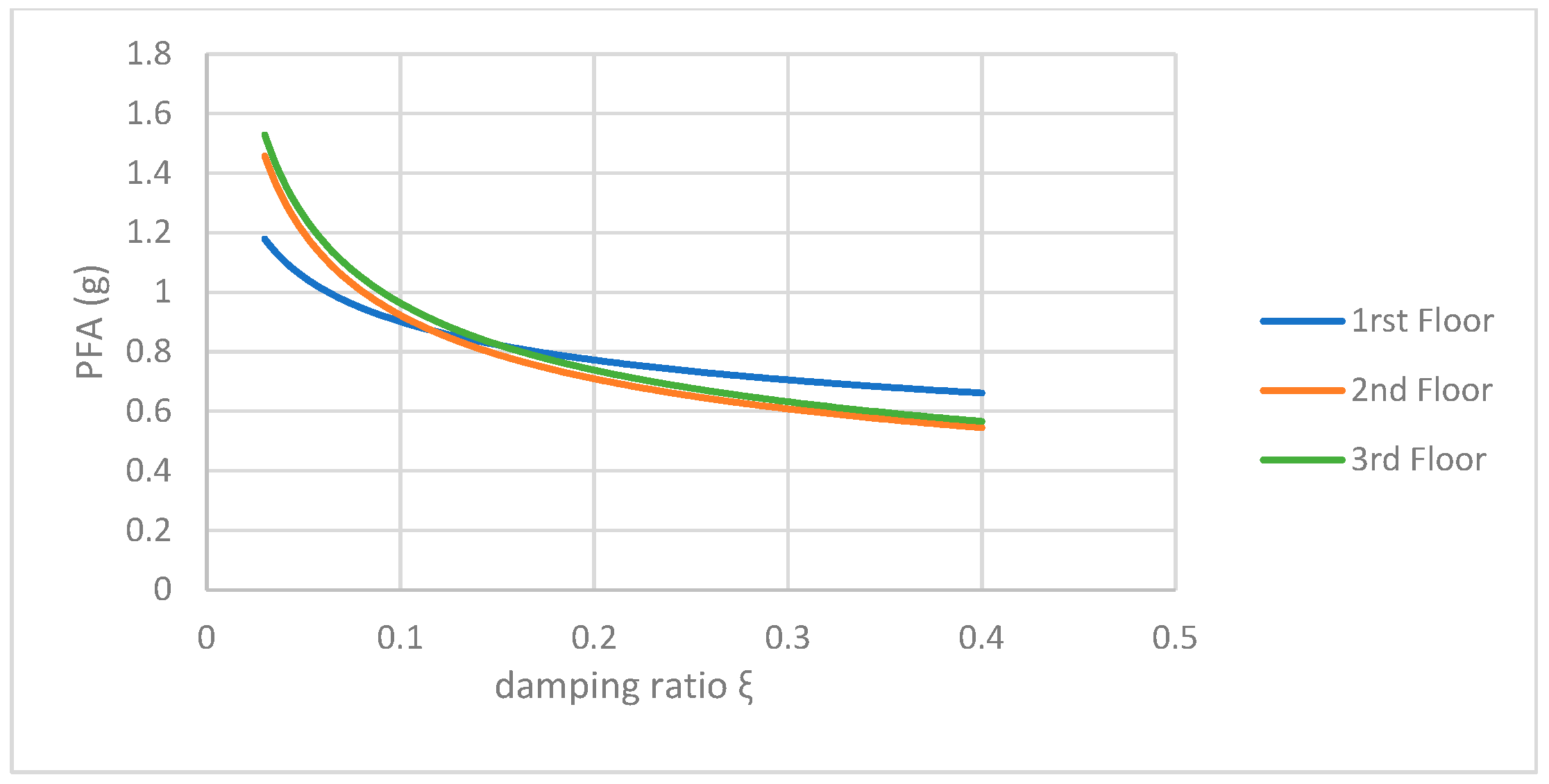
The analysis of Figure 10 and Figure 11 marks the relation between peak floor acceleration (PFA) and the two damping parameters, which are shown in two different ways for the three-storey structure. Figure 10 illustrates the PFA response as a function of the absolute viscous damping coefficient c. This establishes the direct relationship chamfer and size controlling acceleration. In Figure 11, the same response is shown versus the dimensionless damping ratio. Both figures demonstrate the expected pattern of lower peak floor accelerations, associated with the greater damping, but with very different practical use. The graphical form of the damping coefficient in Figure 10 possesses immediate engineering applicability because they can justify from this graphic what damper needs to be purchased. The figure shows a clear relationship between the damping force capacity required and the physical damping force that needs to be overcome to meet the acceleration limits. The examination of the damping ratio in Figure 11 offers results that are easier to compare with prevailing design codes and performance criteria which are based on reference damping ratios rather than coefficients. Such a combination is especially useful for configuring the resiliency of the structures because the codes impose theoretical limits against the real-world challenges posed by implementing dampers.
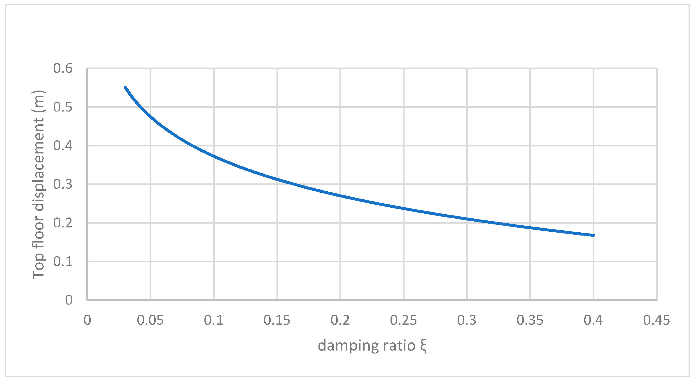
According to Figure 12, the diagram shows how the top joint displacement relates to the damping ratio in a six-storey structural system. The graph clearly illustrates that as the damping ratio increases, the maximum displacement at the top joint of the structure significantly decreases. This means that higher damping ratios lead to better control over structural vibrations. This relationship is crucial for seismic design and structural dynamics analysis, as it highlights how we can optimize damping mechanisms to reduce excessive displacements that might cause structural damage or discomfort for occupants. Typically, the curve follows an exponential decay pattern, where the initial increases in the damping ratio result in the most significant reductions in displacement, while additional increases provide less and less improvement in controlling displacement.
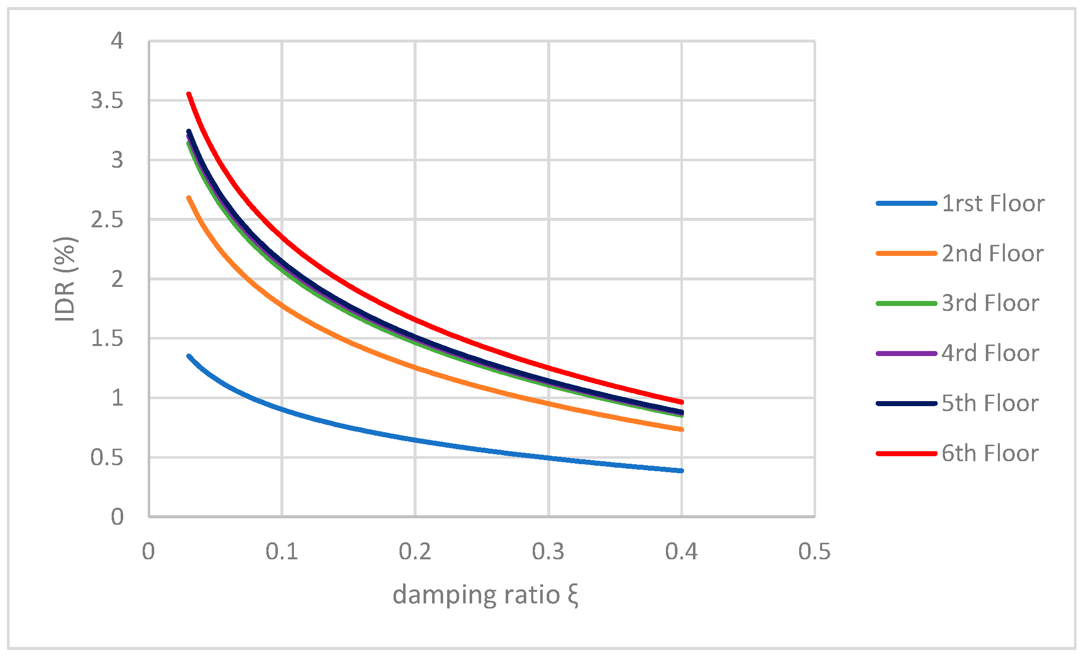
The analysis of Figure 13 and Figure 14 sheds light on the relationship between inter-storey drift ratio (IDR) and damping ratio for the six-storey structure, revealing some notable differences in how the structure responds. Even though they follow a similar parametric framework, these diagrams likely represent different loading conditions, analysis methods, or structural setups within the six-storey system. This dual representation allows for a comparison of various seismic input scenarios, different damping distribution strategies, or variations in structural modeling assumptions. Both figures show a clear trend: as the damping ratio increases, the IDR tends to decrease. However, the extent and speed of this reduction can differ between the two cases, highlighting how sensitive the drift response is to specific design parameters or loading conditions. This comparative analysis is especially useful for understanding how effective damping can be across different scenarios, giving engineers a broader view of expected performance ranges instead of just isolated design values. This insight ultimately helps in making more informed seismic design choices for mid-rise structures.
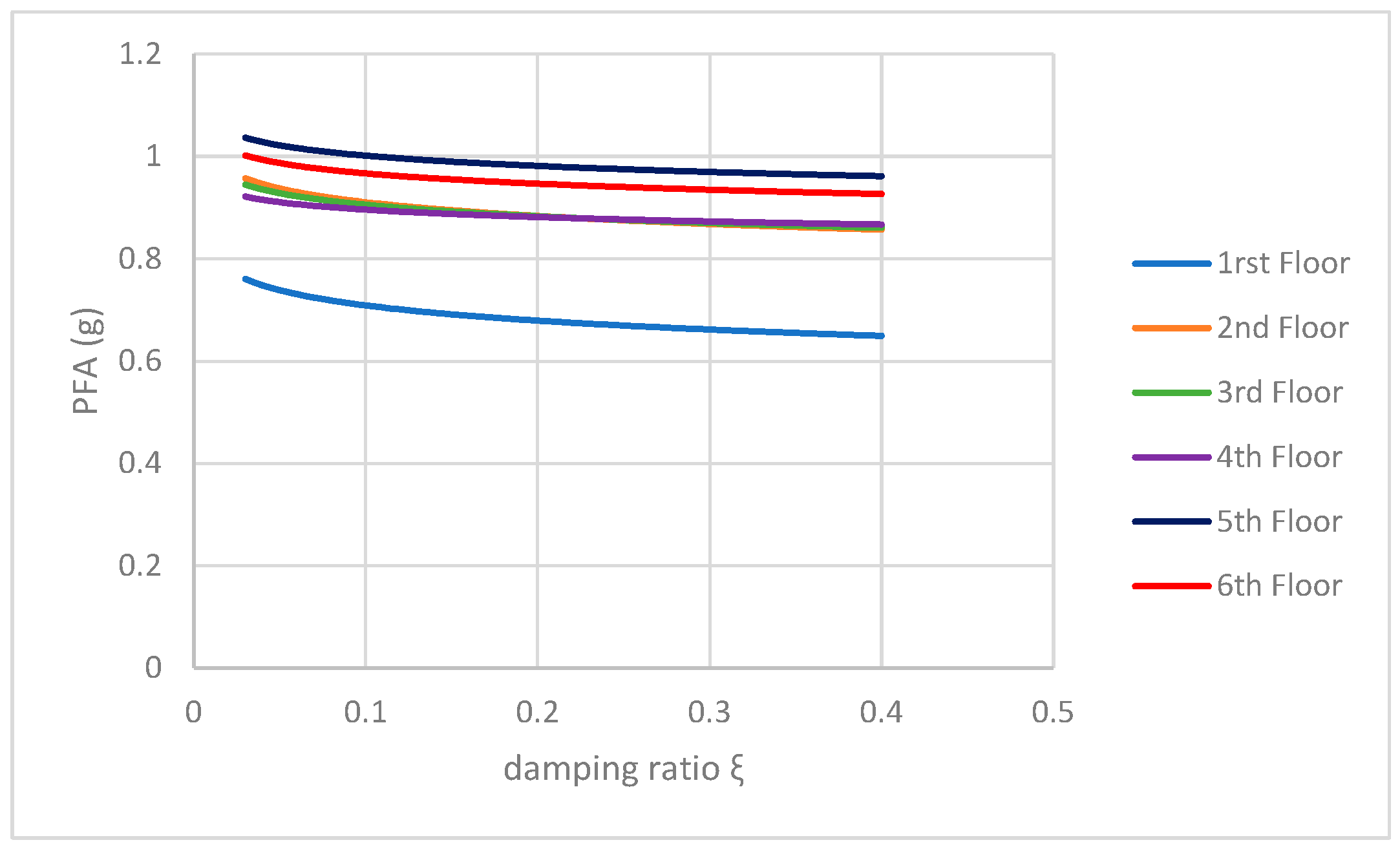
The analysis of Figure 15 and Figure 16 sheds light on the relationship between (PFA) and damping ratio for the six-storey structure, revealing some notable differences in how the structure responds. Even though they follow a similar parametric framework, these diagrams likely represent different loading conditions, analysis methods, or structural setups within the six-storey system. This dual representation allows for a comparison of various seismic input scenarios, different damping distribution strategies, or variations in structural modeling assumptions. Both figures show a clear trend: as the damping ratio increases, the PFA tends to decrease. However, the extent and speed of this reduction can differ between the two cases, highlighting how sensitive the acceleration response is to specific design parameters or loading conditions. This comparative analysis is especially useful for understanding how effective damping can be across different scenarios, giving engineers a broader view of expected performance ranges instead of just isolated design values. This insight ultimately helps in making more informed seismic design choices for mid-rise structures.
By initially taking the IDR equations for the three-story building, the relationships for each floor with and without dampers are equal, creating an equation with two unknowns (ξ and c), and solve for one of the two. The procedure is as follows:
−0.3305 × ln(C) + 3.1657 = 2.8271ξ2 − 2.8340ξ + 1.2954
Final analytical form:
ξ = 2.8340 ± 8.0256 + 31.929 × ( 1.8703 + 0.3305 + ln C ) 5.6542
Similarly, for the second and third floors, the equations are obtained as follows:
ξ = 5.0362 ± 25.3630 + 20.0550 × ( 0.5268   ln c 2.4565 ) 10.0279
ξ = 5.1848 ± 26.8750 17.7610 × ( 1.6735 0.4503   ln c ) 8.8806
The remaining equations were of a simpler form; so, simply moving the terms to one side and dividing by the coefficient or raising to the reciprocal of the exponent of ξ is enough for the following simplified formulas to work.
PFA:
1 st : ξ = 0.8194 c 0.0014
2 nd : ξ = 0.0453 c 0.2105
3 rd : ξ = 0.0081 c 0.3899
Similarly, all equations for the six-storey structure are as follows:
IDR:
1 st ξ = 0.000296 c 0.7333
2 nd ξ = 0.000337 c 0.7682
3 rd ξ = 0.000131 c 0.9010
4 th ξ = 0.000158 c 0.9121
5 th ξ = 0.000534 c 0.8074
6 th ξ = 0.008559 c 0.4857
PFA:
1 st ξ =   e ( ( 0.6100     0.68765 c ( 0.0098 ) ) / 0.04287 )
2 nd ξ = e ( ( 0.8214 0.95145 c ( 0.0531 ) ) / 0.03868 )
3 rd ξ = e ( ( 0.8309 0.88487 c ( 0.0611 ) ) / 0.03244 )
4 th ξ = e ( ( 0.8477 1.13272 c ( 0.0992 ) ) / 0.02098 )
5 th ξ = e ( ( 0.9348 1.54563 c ( 0.1108 ) ) / 0.02895 )
6 th ξ = e ( ( 0.9001 2.70705 c ( 0.1840 ) ) / 0.02902 )
The sixth floor, being the highest level of the building, shows a noticeably different damping behavior compared to the lower floors, and this is due to several key factors in structural dynamics. As the topmost point, Floor 6 faces the greatest displacement amplifications and accelerations during seismic events, making it particularly sensitive to how the structure responds. The equations developed for this floor highlight these amplified dynamic effects, where even slight adjustments in the dampers’ coefficient (c) lead to more significant changes in the required damping ratio (ξ). This increased sensitivity arises because the top floor serves as the endpoint of the building’s whip-like motion during an earthquake, where all the displacements and accelerations from the lower floors come together and intensify. Moreover, the top floor usually has fewer structural constraints compared to the floors in between, making it more vulnerable to larger displacements and necessitating more accurate damping control to satisfy both IDR and PFA performance standards. The mathematical equations for Floor 6 illustrate this amplification effect, revealing steeper gradients in the relationship between the damping coefficient and the damping ratio, which is crucial for engineers when designing supplemental damping systems for tall buildings.
Focusing on the analysis of planar steel frames, this study reveals that the fundamental damping relationships developed are also relevant to spatial steel frame structures. The empirical equations effectively capture the essential physics of viscous damping behavior, which remains consistent irrespective of the structural model’s dimensional complexity. However, for spatial frames, it is necessary to give due consideration to torsional effects and multi-directional response characteristics that could influence the absolute values of the damping coefficients, while still preserving the foundational relationships established in this research.
The viscous damping ratio range, which spans from 3% to 40%, includes both the inherent structural damping, typically ranging from 2% to 5%, and the entire spectrum of additional damping that can be achieved through various damping systems. Modern applications in seismic retrofitting and high-performance design often utilize supplemental damping systems that can enhance effective damping ratios to between 20% and 40%. This range ensures that empirical relationships account for all practical design scenarios, from conventional construction to advanced seismic protection systems. The correlation between damping ratios and building height is inherently captured through separate analyses of three-story and six-story structures.
The present methodology is developed within the framework of linear elastic structural behavior, with all analyses conducted using linear time-history procedures. The structures are assumed to remain in the elastic range where global structural response is maintained and localized collapse mechanisms do not form. This assumption is consistent with performance-based design approaches for supplementally damped structures under design-level seismic events, where properly sized damping devices help ensure uniform drift distributions. The empirical relationships are therefore applicable to design scenarios where structures perform within or near their elastic limits, representing typical practical seismic design cases.

5. Comparison with Existing Methods and Discussion

The developed equations were compared against established approaches from the literature to assess their validity and accuracy. Specifically, comparisons were made with the methods detailed below.

5.1. Comparison with Hatzigeorgiou [36] Method

Three representative cases were selected for comparison with the damping modification factor approach proposed by Hatzigeorgiou [36] (Table 4):

5.2. Comparison with Logotheti et al.’s [38] Approach

The inter-storey velocity relationships from Logotheti et al. [38] were used to indirectly validate the damping coefficient predictions (Table 5):

5.3. Discussion

The present study adopts a two-dimensional linear elastic framework with uniform damper distribution to establish fundamental predictive relationships suitable for preliminary design applications. While this approach enables the derivation of generalizable closed-form equations through controlled parametric analysis, it inherently does not capture certain complexities present in real structures, including frame nonlinearity under severe seismic excitation, three-dimensional torsional coupling effects, and potential benefits of non-uniform damper distributions. The averaging procedure employed to condense the parametric database introduces some variability, though the statistical validation demonstrates acceptable predictive accuracy within the defined scope. These empirical relationships are intended as practical tools for initial damper sizing and rapid performance assessment, providing engineers with direct estimates that can significantly reduce computational effort during preliminary design stages. For the final design of structures with significant irregularities or anticipated nonlinear response, these equations should be complemented by detailed nonlinear time-history analyses to verify performance under project-specific conditions.

6. Conclusions

This research has established empirical relationships between viscous damping characteristics and structural response parameters for two-dimensional steel frame buildings through an extensive parametric analysis of three-story and six-story configurations. The primary contributions of this study include the creation of a comprehensive database comprising 1190 analytical cases with diverse damping configurations and seismic loading scenarios, the derivation of regression equations that demonstrate strong correlations between damping coefficients and key structural performance metrics including inter-story drift ratios, peak floor accelerations, and top floor displacements, and the development of closed-form expressions that enable a preliminary assessment of viscous damper systems without requiring iterative computational procedures.
The proposed empirical relationships are derived under specific modeling conditions that define their scope of applicability. This study employs two-dimensional planar frame models with linear elastic analysis and assumes uniform damper distribution across building height with equal damping coefficients at all stories. These controlled conditions enable the isolation of fundamental relationships between the damping parameters and the structural response, providing a systematic methodology for preliminary damper sizing that can significantly reduce computational effort during initial design stages. However, these simplifications inherently limit direct extrapolation to more complex scenarios. The two-dimensional linear elastic framework does not capture frame nonlinearity under severe seismic excitation, three-dimensional torsional coupling effects that may arise in spatially irregular structures, or potential advantages of non-uniform damper distributions optimized for specific structural configurations. Additionally, the averaging procedure employed to condense the extensive parametric database introduces some variability in predictions, and the current formulations do not explicitly incorporate natural frequency characteristics or higher-order dynamic effects that may influence the response under certain loading conditions.
The empirical equations developed in this study are intended as practical tools for preliminary design and rapid performance assessment of steel frames equipped with viscous dampers. They provide engineers with direct estimates of required damping coefficients based on target performance criteria, thereby streamlining the initial design phase. For structures with significant irregularities, anticipated nonlinear behavior, or three-dimensional effects, these preliminary estimates should be verified and refined through detailed nonlinear time-history analyses that account for project-specific complexities. Future research extensions could address validation through experimental testing, incorporation of nonlinear frame behavior, investigation of non-uniform damper distributions, and development of analogous relationships for three-dimensional models with torsional considerations. Despite the noted limitations, the methodology established and the empirical relationships derived provide a robust foundation for advancing preliminary design procedures in seismic retrofitting applications involving passive viscous damping systems.

Author Contributions

Conceptualization, G.D.H.; methodology, P.K.; software, P.D.; validation, G.D.H., writing—original draft preparation, P.D.; writing—review and editing, P.K.; visualization, P.K.; supervision, P.K. All authors have read and agreed to the published version of the manuscript.

Funding

This research project is co-financed by the Hellenic Open University and the Greek Ministry of Education and Religious Affairs (research project 80707).

Institutional Review Board Statement

Not applicable.

Informed Consent Statement

Not applicable.

Data Availability Statement

Data is contained within this article.

Conflicts of Interest

The authors declare no conflicts of interest.

References

  1. Kitayama, S.; Constantinou, M.C. Seismic Performance of Buildings with Viscous Damping Systems Designed by the Procedures of ASCE/SEI 7-16. J. Struct. Eng. 2018, 144, 4018050. [Google Scholar] [CrossRef]
  2. Christopoulos, C.; Filiatrault, A. Principles of Passive Supplemental Damping and Seismic Isolation; IUSS Press: Pavia, Italy, 2006. [Google Scholar]
  3. Wang, S.; Mahin, S.A. Seismic retrofit of a high-rise steel moment-resisting frame using fluid viscous dampers. Struct. Des. Tall Spec. Build. 2017, 26, e1367. [Google Scholar] [CrossRef]
  4. Lavan, O. A methodology for the integrated seismic design of nonlinear buildings with supplemental damping. Struct. Control Health Monit. 2015, 22, 484–499. [Google Scholar]
  5. Constantinou, M.C.; Tadjbakhsh, I.G. Optimum design of a first story damping system. Comput. Struct. 1983, 17, 305–310. [Google Scholar] [CrossRef]
  6. Symans, M.D.; Charney, F.A.; Whittaker, A.S.; Constantinou, M.C.; Kircher, C.A.; Johnson, M.W.; McNamara, R.J. Energy dissipation systems for seismic applications: Current practice and recent developments. J. Struct. Eng. ASCE 2008, 134, 3–21. [Google Scholar] [CrossRef]
  7. Mahjoubi, S.; Maleki, S. Seismic performance evaluation and design of steel structures equipped with dual-pipe dampers. J. Constr. Steel Res. 2016, 122, 25–39. [Google Scholar] [CrossRef]
  8. Zhu, X.; Jing, X.; Cheng, L. Magnetorheological fluid dampers: A review on structure design and analysis. J. Intell. Mater. Syst. Struct. 2012, 23, 839–873. [Google Scholar]
  9. Salaas, B.; Bekdaş, G.; Ibrahim, Y.E.; Nigdeli, S.M.; Ezzat, M.; Nawar, M.; Kayabekir, A.E. Design optimization of a hybrid vibration control system for buildings. Buildings 2023, 13, 934. [Google Scholar]
  10. Zhang, H.; Li, A.; Su, Y.; Xu, G.; Sha, B. Viscoelastic Dampers for Civil Engineering Structures: A Systematic Review of Constructions, Materials, and Applications. J. Build. Eng. 2024, 96, 110597. [Google Scholar]
  11. Yuan, X.; Tian, T.; Ling, H.; Qiu, T.; He, H. A review on structural development of magnetorheological fluid damper. Shock Vib. 2019, 2019, 1498962. [Google Scholar] [CrossRef]
  12. Papagiannopoulos, G.A.; Hatzigeorgiou, G.D.; Beskos, D.E. Design Using Supplemental Dampers. In Seismic Design Methods for Steel Building Structures; Springer: Berlin/Heidelberg, Germany, 2021; pp. 463–508. [Google Scholar]
  13. Landi, L.; Lucchi, S.; Diotallevi, P.P. A procedure for the direct determination of the required supplemental damping for the seismic retrofit with viscous dampers. Eng. Struct. 2014, 71, 137–149. [Google Scholar] [CrossRef]
  14. Lavan, O. Optimal design of viscous dampers and their supporting members for the seismic retrofitting of 3D irregular frame structures. J. Struct. Eng. 2015, 141, 04015026. [Google Scholar] [CrossRef]
  15. Nuzzo, I.; Losanno, D.; Caterino, N. Seismic design and retrofit of frame structures with hysteretic dampers: A simplified displacement-based procedure. Bull. Earthq. Eng. 2019, 17, 2787–2819. [Google Scholar] [CrossRef]
  16. Marioni, A. Seismic retrofitting of existing structures. In Anti-Seismic Devices: A Reference Manual for Structural Engineers; Springer International Publishing: Cham, Switzerland, 2024; pp. 145–168. [Google Scholar]
  17. Marioni, A. Testing Requirements of Anti-seismic Devices and Available Testing Facilities. In Anti-Seismic Devices: A Reference Manual for Structural Engineers; Springer International Publishing: Cham, Switzerland, 2024; pp. 85–109. [Google Scholar]
  18. Stanikzai, M.H.; Elias, S.; Chae, Y. Recent advances in hybrid vibration-control systems. Pract. Period. Struct. Des. Constr. 2022, 27, 03122003. [Google Scholar] [CrossRef]
  19. Shu, Z.; You, R.; Xie, Y. Viscoelastic Dampers for Vibration Control of Building Structures: A State-of-Art Review. J. Earthq. Eng. 2024, 28, 3558–3585. [Google Scholar] [CrossRef]
  20. Patil, A.Y.; Patil, R.D. A review on seismic analysis of a multi-storied steel building provided with different types of damper and base isolation. Asian J. Civ. Eng. 2024, 25, 3277–3283. [Google Scholar] [CrossRef]
  21. Almajhali, K.Y.M.; Alhaddad, W. A systematic review of hybrid passive energy dissipating devices. Proc. Inst. Civ. Eng. Struct. Build. 2024, 1–43. [Google Scholar]
  22. Silwal, B.; Michael, R.J.; Ozbulut, O.E. A superelastic viscous damper for enhanced seismic performance of steel moment frames. Eng. Struct. 2015, 105, 152–164. [Google Scholar] [CrossRef]
  23. Lavan, O.; Amir, O. Simultaneous topology and sizing optimization of viscous dampers in seismic retrofitting of 3D irregular frame structures. Earthq. Eng. Struct. Dyn. 2014, 43, 1325–1342. [Google Scholar] [CrossRef]
  24. Güllü, A.; Körpeoğlu, S.G.; Selek Kılıçarslan, E.S. Multi-objective optimal sizing of energy dissipative steel cushions for longitudinal loading. Struct. Multidiscip. Optim. 2021, 63, 2955–2967. [Google Scholar] [CrossRef]
  25. Nabid, N.; Hajirasouliha, I.; Petkovski, M. Adaptive low computational cost optimisation method for Performance-based seismic design of friction dampers. Eng. Struct. 2019, 198, 109549. [Google Scholar] [CrossRef]
  26. Wang, S.; Mahin, S.A. High-performance computer-aided optimization of viscous dampers for improving the seismic performance of a tall building. Soil Dyn. Earthq. Eng. 2018, 113, 454–461. [Google Scholar] [CrossRef]
  27. Kang, J.D.; Tagawa, H. Experimental evaluation of dynamic characteristics of seesaw energy dissipation system for vibration control of structures. Earthq. Eng. Struct. Dyn. 2014, 43, 1889–1895. [Google Scholar] [CrossRef]
  28. Tagawa, H.; Yamanishi, T.; Takaki, A.; Chan, R.W. Cyclic behavior of seesaw energy dissipation system with steel slit dampers. J. Constr. Steel Res. 2016, 117, 24–34. [Google Scholar] [CrossRef]
  29. Kang, J.D.; Tagawa, H. Comparison between experimental and analytical results for seesaw energy dissipation systems using fluid viscous dampers. Earthq. Eng. Eng. Vib. 2016, 15, 79–90. [Google Scholar] [CrossRef]
  30. Katsimpini, P.S.; Askouni, P.K.; Papagiannopoulos, G.A.; Karabalis, D.L. Seismic drift response of seesaw-braced and buckling-restrained braced steel structures: A comparison study. Soil Dyn. Earthq. Eng. 2020, 129, 105925. [Google Scholar] [CrossRef]
  31. Katsimpini, P.S.; Papagiannopoulos, G.A.; Askouni, P.K.; Karabalis, D.L. Seismic response of low-rise 3-D steel structures equipped with the seesaw system. Soil Dyn. Earthq. Eng. 2020, 128, 105877. [Google Scholar] [CrossRef]
  32. Katsimpini, P.S.; Papagiannopoulos, G.A. Effectiveness of the seesaw system as a means of seismic upgrading in older, non-ductile reinforced concrete buildings. Vibration 2023, 6, 102–112. [Google Scholar] [CrossRef]
  33. Mo, Z.; Shu, G.; Lai, B.; Ventura, C.E.; Yang, T. Experimental behavior, numerical modeling and parameters evaluation of three-dimensional seismic isolation device. J. Constr. Steel Res. 2024, 220, 108817. [Google Scholar] [CrossRef]
  34. Mo, Z.; Lai, B.; Shu, G.; Chen, P.; Yang, T. Performance-based seismic design method of stacked modular steel building based on three-dimensional seismic isolation. Eng. Struct. 2025, 336, 120438. [Google Scholar] [CrossRef]
  35. Banazadeh, M.; Ghanbari, A. Seismic performance assessment of steel moment-resisting frames equipped with linear and nonlinear fluid viscous dampers with the same damping ratio. J. Constr. Steel Res. 2017, 136, 215–228. [Google Scholar] [CrossRef]
  36. Hatzigeorgiou, G.D. Damping modification factors for SDOF systems subjected to near-fault, far-fault and artificial earthquakes. Earthq. Engng. Struct. Dyn. 2010, 39, 1239–1258. [Google Scholar] [CrossRef]
  37. Hatzigeorgiou, G.D.; Pnevmatikos, N.G. Maximum damping forces for structures with viscous dampers under near-source earthquakes. Eng. Struct. 2014, 68, 1–13. [Google Scholar] [CrossRef]
  38. Logotheti, V.E.; Kafetzi, T.C.; Papagiannopoulos, G.A.; Karabalis, D.L. On the use of interstorey velocity for the seismic retrofit of steel frames with viscous dampers. Soil Dyn. Earthq. Eng. 2020, 129, 105312. [Google Scholar] [CrossRef]
  39. Mavroeidakos, P.; Katsimpini, P.; Papagiannopoulos, G. Effect of Viscous Dampers with Variable Capacity on the Response of Steel Buildings. Vibration 2025, 8, 11. [Google Scholar] [CrossRef]
  40. Kolour, N.A.; Basim, M.C.; Chenaghlou, M. Multi-objective optimum design of nonlinear viscous dampers in steel structures based on life cycle cost. Structures 2021, 34, 3776–3788. [Google Scholar] [CrossRef]
  41. Gharagoz, M.M.; Noureldin, M.; Kim, J. Machine learning-based design of a seismic retrofit frame with spring-rotational friction dampers. Eng. Struct. 2023, 292, 116053. [Google Scholar]
  42. Wen, J.; Han, Q.; Xie, Y.; Du, X.; Zhang, J. Performance-based seismic design and optimization of damper devices for cable-stayed bridge. Eng. Struct. 2021, 237, 112043. [Google Scholar] [CrossRef]
  43. Takewaki, I. Building Control with Passive Dampers: Optimal Performance-Based Design for Earthquakes; John Wiley & Sons: Hoboken, NJ, USA, 2009. [Google Scholar]
  44. Aydin, E.; Boduroglu, M.H.; Guney, D. Optimal damper distribution for seismic rehabilitation of planar building structures. Eng. Struct. 2007, 29, 176–185. [Google Scholar] [CrossRef]
  45. Lavan, O. On the efficiency of viscous dampers in reducing various seismic responses of wall structures. Earthq. Eng. Struct. Dyn. 2012, 41, 1673–1692. [Google Scholar] [CrossRef]
  46. Palermo, M.; Muscio, S.; Silvestri, S.; Landi, L.; Trombetti, T. On the dimensioning of viscous dampers for the mitigation of the earthquake-induced effects in moment-resisting frame structures. Bull. Earthq. Eng. 2013, 11, 2429–2446. [Google Scholar] [CrossRef]
  47. Montuori, R.; Muscati, R. Plastic design of seismic resistant reinforced concrete frame. Earthq. Struct. 2015, 8, 205–224. [Google Scholar] [CrossRef]
  48. Montuori, R.; Muscati, R. Smart and simple design of seismic resistant reinforced concrete frame. Compos. Part B Eng. 2017, 115, 360–368. [Google Scholar] [CrossRef]
  49. Peng, Y.; Sun, P. Reliability-based design optimization of tuned mass-damper-inerter for mitigating structural vibration. J. Sound Vib. 2024, 572, 118166. [Google Scholar] [CrossRef]
  50. Song, C.; Xiao, R.; Jiang, Z.; Sun, B. Active-learning Kriging-assisted robust design optimization of tuned mass dampers: Vibration mitigation of a steel-arch footbridge. Eng. Struct. 2024, 303, 117502. [Google Scholar]
  51. Sanati, S.H.; Karamodin, A. Optimum seismic design of frame structures with and without metallic yielding dampers considering life-cycle cost. J. Build. Eng. 2023, 76, 107335. [Google Scholar] [CrossRef]
  52. Li, Y.; Tan, P.; Li, S.; He, H. A novel tuned inerter eddy current damper: Modeling, optimization, and evaluation. Eng. Struct. 2023, 285, 116026. [Google Scholar] [CrossRef]
  53. Wang, L.; Zhou, Y.; Shi, W. Seismic control of a smart structure with semiactive tuned mass damper and adaptive stiffness property. Earthq. Eng. Resil. 2023, 2, 74–93. [Google Scholar] [CrossRef]
  54. Jafarzadeh, O.; Mousavi Ghasemi, S.A.; Zahrai, S.M.; Mohammadzadeh, A.; Vafaei Poursorkhabi, R. Online adaptive neurochaotic fuzzy controller design to reduce the seismic response of buildings equipped with active tuned mass damper system. Int. J. Intell. Syst. 2023, 2023, 8460498. [Google Scholar] [CrossRef]
  55. Zhang, H.; Wang, L.; Shi, W. Seismic control of adaptive variable stiffness intelligent structures using fuzzy control strategy combined with LSTM. J. Build. Eng. 2023, 78, 107549. [Google Scholar] [CrossRef]
  56. Ghanemi, N.E.; Abdeddaim, M.; Ounis, A. Artificial Intelligence-Driven Active Tuned Mass Damper for Enhanced Seismic Resilience of Shear Frame Smart Structures. J. Vib. Eng. Technol. 2024, 12, 1577–1599. [Google Scholar] [CrossRef]
  57. Jafarzadeh, O.; Sabetahd, R.; Ghasemi, S.A.M.; Zahrai, S.M. Design of a novel intelligent adaptive fractional-order proportional-integral-derivative controller for mitigation of seismic vibrations of a building equipped with an active tuned mass damper. Smart Mater. Struct. 2024, 33, 095020. [Google Scholar] [CrossRef]
  58. Wani, Z.R.; Tantray, M.; Farsangi, E.N. Adaptive System Supervising the Response Control for Smart Structures. In Automation in Construction toward Resilience; CRC Press: Boca Raton, FL, USA, 2023; pp. 277–316. [Google Scholar]
  59. Ghasemi, S.; Hosseini, M.; Hu, S.; Shahram, A. Seismic isolation strategy via controlled soft first story with innovative multi-stage yielding damper: Experimental and numerical insights. Structures 2024, 70, 107553. [Google Scholar] [CrossRef]
  60. Bruschi, E.; Zoccolini, L.; Cattaneo, S.; Quaglini, V. Experimental characterization, modeling, and numerical evaluation of a novel friction damper for the seismic upgrade of existing buildings. Materials 2023, 16, 1933. [Google Scholar] [CrossRef]
  61. Almajhali, K.Y.M. Review on passive energy dissipation devices and techniques of installation for high rise building structures. Structures 2023, 51, 1019–1029. [Google Scholar] [CrossRef]
  62. Ahmadi, M.; Ebadi-Jamkhaneh, M. Seismic upgrading of existing steel buildings built on soft soil using passive damping systems. Buildings 2023, 13, 1587. [Google Scholar] [CrossRef]
  63. Yang, Y.; Xu, Z.D.; Huang, X.H.; Dong, Y.R.; Dai, J.; Li, Y.J. Ant colony-inspired cooperative control of multi-magnetorheological dampers system for coupled vibration mitigation of spatial irregular structures. Eng. Struct. 2025, 334, 120241. [Google Scholar] [CrossRef]
  64. Ding, L.; Jiao, H. Performance Analysis of Yielding Tubular Dampers in Steel Frame Knee Braces: A Finite Element Study. Int. J. Steel Struct. 2025, 25, 95–110. [Google Scholar]
  65. Zhang, P.; Yam, M.C.; Ke, K.; Song, Y.; Zhu, M. Experimental study of a self-centering damper with multistage energy-dissipation mechanism. J. Struct. Eng. 2024, 150, 04024166. [Google Scholar]
  66. Saeedi, A.; Khatibinia, M.; Mohtashami, E. Optimum distribution and design of friction-damped diagonal brace for reducing seismic damage of steel moment-resisting frames. Struct. Infrastruct. Eng. 2025, 1–21. [Google Scholar] [CrossRef]
  67. Sattari, A.; Maleki, A.; Lotfollahi-Yaghin, M.A. Seismic Evaluation of Composite Steel Moment Frames with Brace Members and Rotational Friction Dampers under Near-Fault Earthquakes. Numer. Methods Civ. Eng. 2025, 9, 9–23. [Google Scholar] [CrossRef]
  68. Kye, S.; Jung, H.; Jung, H.J. Experimental investigation on the hysteretic dynamics of a regenerative hybrid electrodynamic cable damper. Struct. Infrastruct. Eng. 2024, 20, 407–420. [Google Scholar] [CrossRef]
  69. Karami, M.; Estekanchi, H.E.; Hajirasouliha, I.; Mirfarhadi, S.A. Optimal properties of nonlinear viscous dampers in steel structures considering the life cycle cost. J. Earthq. Eng. 2024, 28, 1685–1708. [Google Scholar] [CrossRef]
  70. Katsimpini, P.; Papagiannopoulos, G.; Hatzigeorgiou, G. A Thorough Examination of Innovative Supplementary Dampers Aimed at Enhancing the Seismic Behavior of Structural Systems. Appl. Sci. 2025, 15, 1226. [Google Scholar] [CrossRef]
  71. SAP 2000. Static and Dynamic Finite Element Analysis of Structures: Version 25.0; Computers and Structures: Berkeley, CA, USA, 2023. [Google Scholar]
  72. EN 1993-1; Eurocode 3. Design of Steel Structures—Part 1.1: General Rules and Rules for Buildings. Committee for Standardization (CEN): Brussels, Belgium, 2009.
  73. Eurocode 8. Design of Structures for Earthquake Resistance, Part 1–1: General Rules, Seismic Actions and Rules for Buildings; European Committee for Standardization (CEN): Brussels, Belgium, 2005. [Google Scholar]
  74. National Research Institute for Earth Science and Disaster Resilience. NIED K-NET, KiK-Net; National Research Institute for Earth Science and Disaster Resilience: Tsukuba, Japan, 2019. [Google Scholar]
  75. Available online: https://www.taylordevices.com/products/fluid-viscous-dampers/ (accessed on 23 April 2025).
  76. Microsoft Corporation. Microsoft Excel, version 2021. Microsoft 2021. Available online: www.microsoft.com/en-us/microsoft-365/excel (accessed on 23 April 2025).
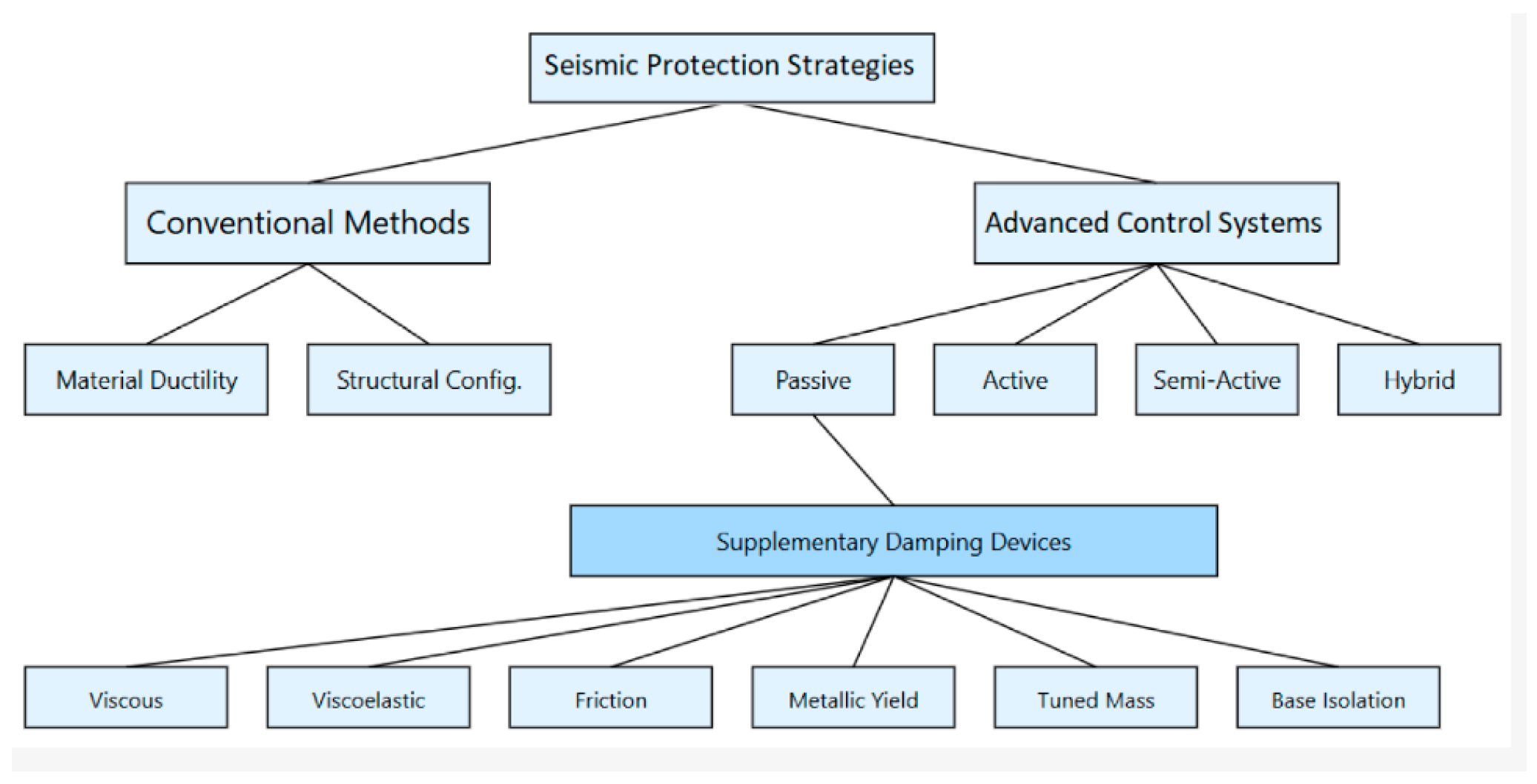
Figure 1. Seismic protection strategies [64].
Eng 06 00308 g001
Figure 2. Three-storey structure.
Eng 06 00308 g002
Figure 3. Six-storey structure.
Eng 06 00308 g003
Figure 4. Three-storey structure with viscous dampers.
Eng 06 00308 g004
Figure 5. Six-storey structure with viscous dampers.
Eng 06 00308 g005
Figure 6. Spectrum of seismic motions.
Eng 06 00308 g006
Figure 7. Diagram of top joint displacement vs. viscous damping ratio (three-storey structure).
Eng 06 00308 g007
Figure 8. Diagram of IDR (%) vs. damping ratio (three-storey structure).
Eng 06 00308 g008
Figure 9. Diagram of IDR (%) vs. dampers’ coefficient c (three-storey structure).
Eng 06 00308 g009
Figure 10. Diagram of PFA (g) vs. dampers’ coefficient c (three-storey structure).
Eng 06 00308 g010
Figure 11. Diagram of PFA (g) vs. damping ratio (three-storey structure).
Eng 06 00308 g011
Figure 12. Diagram of top joint displacement vs. damping ratio (six-storey structure).
Eng 06 00308 g012
Figure 13. Diagram of IDR (%) vs. damping ratio (six-storey structure).
Eng 06 00308 g013
Figure 14. Diagram of IDR (%) vs. dampers’ coefficient c (six-storey structure).
Eng 06 00308 g014
Figure 15. Diagram of PFA (g) vs. dampers’ coefficient c (six-storey structure).
Eng 06 00308 g015
Figure 16. Diagram of PFA (g) vs. damping ratio (six-storey structure).
Eng 06 00308 g016
Table 1. Sections of the three- and six-story buildings.
Three-Story BuildingSix-Story Building
 beamscolumnsBeamscolumns
Floor 1–2ΙΡΕ240HΕ360ΒΙΡΕ360HΕ360Β
Floor 3ΙΡΕ240HΕ360ΒΙΡΕ300HΕ360Β
Floor 4--ΙΡΕ300HΕ300Β
Floors 5–6--ΙΡΕ270HΕ300Β
Table 2. Seismic motions.
No.Earthquake, LocationDateRecording StationMwSoil TypePGA (m/s2)
1Loma Prieta, USA17 October 1989Los Gatos7HR5.53
2San Fernando, USA9 February 1971Pacoima Dam6.6HR12.03
3Northridge, USA17 January 1994Rinaldi Receiving St.6.7SL8.22
4Northridge, USA17 January 1994Newhall6.7SL5.72
5Maule, Chile27 February 2010Constitución8.8SR6.40
6Christchurch, New Zealand22 February 2011Resthaven6.3SL6.99
7Cape Mendocino, CA, USA25 October 1992Petrolia6.9SR14.69
Table 3. Derived Equations.
3-story building
Damping ratio (ξ)/Top floor displacement (y)y = 1.1632ξ2 − 0.8816ξ + 0.2535
1st floor2nd floor3rd floor
Damping ratio (ξ)/IDR%IDR = 2.8271ξ2 − 2.8340ξ + 1.2954y = 5.0140ξ2 − 5.0362ξ + 2.493y = 4.4403ξ2 − 5.1848ξ + 2.5580
Damping ratio (ξ)/PFA PFA = 0.5395ξ−0.2228PFA = 0.3851ξ−0.3795PFA = 0.3985ξ−0.3833
Dampers’ coefficient c—IDR(%) IDR = −0.3305ln(c) + 3.1657IDR = −0.5268ln(c) + 4.9499IDR = −0.4503ln(c) + 4.2315
Dampers’ coefficient c—PFAPFA = 0.5598c−0.0003PFA = 1.4303c−0.0799PFA = 3.6262c−0.1495
6-story building
Damping ratio (ξ)/Top floor displacement (y)y = −0.14775ln(ξ) + 0.032375
 1st floor2nd floor3rd floor
Damping ratio (ξ)/IDR (%)IDR = −0.3723ln(ξ) + 0.0461IDR = −0.7516ln(ξ) + 0.0461IDR = −0.8823ln(ξ) + 0.0462
Damping ratio (ξ)/PFAPFA = −0.0429ln(ξ) + 0.6100PFA = −0.0387ln(ξ) + 0.8214PFA = −0.0324ln(ξ) + 0.8309
Dampers’ coefficient c—IDR IDR = −0.2730ln(c) + 3.0733IDR = −0.5772ln(c) + 6.0520IDR = −0.7950ln(c) + 7.9303
Dampers’ coefficient c—PFAPFA = 0.6877c−0.0098PFA = 0.9515c−0.0531PFA = 0.8849c−0.0611
 4th floor5th floor6th floor
Damping ratio (ξ)/IDR (%) IDR = −0.8995ln(ξ) + 0.0486IDR = −0.9113ln(ξ) + 0.0461IDR = −1.0003ln(ξ) + 0.0483
Damping ratio (ξ)/PFA PFA = −0.0210ln(ξ) + 0.8477PFA = −0.0290ln(ξ) + 0.9348PFA = −0.02902ln(ξ) + 0.9002
Dampers’ coefficient c—IDR (%) IDR = −0.8203ln(c) + 7.9177IDR = −0.7358ln(c) + 6.9222IDR = −0.4857ln(c) + 4.8054
Dampers’ coefficient c—PFA PFA = 1.1327c−0.0992PFA = 1.5456c−0.1108PFA = 2.70705c−0.1840
Table 4. Comparison with Hatzigeorgiou [36] Method.
Casec (kN·s/m)Present Study ξHatzigeorgiou ξDifference (%)
3-story, 1st floor10000.1420.15811.3
3-story, 1st floor30000.2870.271−5.6
6-story, 3rd floor20000.1950.2034.1
6-story, 6th floor40000.3410.328−3.8
Average absolute difference: 6.2%
Table 5. Validation using Inter-storey Velocity Method.
BuildingFloorIDR (%)Present c (kN·s/m)Logotheti-Based cRatio
3-story1st1.5125011801.06
3-story2nd2.0158016200.98
6-story3rd1.8210022800.92
6-story6th2.2285026501.08
Average ratio: 1.01 (±6%)
Disclaimer/Publisher’s Note: The statements, opinions and data contained in all publications are solely those of the individual author(s) and contributor(s) and not of MDPI and/or the editor(s). MDPI and/or the editor(s) disclaim responsibility for any injury to people or property resulting from any ideas, methods, instructions or products referred to in the content.