Article

Identification of Critical and Post-Critical States of a Drill String Under Dynamic Conditions During the Deepening of Directional Wells

Drilling Wells Department, Faculty of Oil and Gas Engineering, Empress Catherine II Saint Petersburg Mining University, Saint-Petersburg 199106, Russia
*
Author to whom correspondence should be addressed.
Eng 2025, 6(11), 306; https://doi.org/10.3390/eng6110306
Submission received: 23 September 2025 / Revised: 25 October 2025 / Accepted: 29 October 2025 / Published: 3 November 2025
(This article belongs to the Section Chemical, Civil and Environmental Engineering)

Abstract

When drilling inclined and horizontal sections, a significant part of the drill string is in a compressed state which leads to a loss of stability and longitudinal bending. Modeling of the stress–strain state (SSS) of the drill string (DS), including prediction of its stability loss, is carried out using modern software packages; the basis of the software’s mathematical apparatus and algorithms is represented by deterministic statically defined formulae and equations. At the same time, a number of factors such as the friction of the drill string against the borehole wall, the presence of tool joints, drill string dynamic operating conditions, and the uncertainty of the position of the borehole in space cast doubt on the accuracy of the calculations and the reliability of the predictive models. This paper attempts to refine the actual behavior of the drill string in critical and post-critical conditions. To study the influence of dynamic conditions in the well on changes in the SSS of the DS due to its buckling, the following initial data were used: a drill pipe with an outer diameter of 88.9 mm and tool joints causing pipe deflection under gravitational acceleration of 9.81 m/s2 placed in a horizontal wellbore with a diameter of 152.4 mm; axial vibrations with an amplitude of variable force of 15–80 kN and a frequency of 1–35 Hz; lateral vibrations with an amplitude of variable impact of 0.5–1.5 g and a frequency of 1–35 Hz; and an increasing axial load of up to 500 kN. A series of experiments are conducted with or without friction of the drill string against the wellbore walls. The results of computational experiments indicate a stabilizing effect of friction forces. It should be noted that the distance between tool joints and their diametrical ratio to the borehole, taking into account gravitational acceleration, has a stabilizing effect due to the formation of additional contact force and bending stresses. It was established that drill string vibrations may either provide a stabilizing effect or lead to a loss of stability, depending on the combination of their frequency and vibration type, as well as the amplitude of variable loading. In the experiments without friction, the range of critical loads under vibration varied from 85 to >500 kN, compared to 268 kN as obtained in the reference experiment without vibrations. In the presence of friction, the range was 150 to >500 kN, while in the reference experiment without vibrations, no buckling was observed. Based on the results of this study, it is proposed to monitor the deformation rate of the string during loading as a criterion for identifying buckling in the DS stress–strain state monitoring system.

1. Introduction

The drilling of oil and gas wells is increasingly performed along complex spatial trajectories. This is due to the need to develop hard-to-reach areas, including the Arctic shelf and swampy and impassable territories [1]. For trouble-free deepening of wells in intervals represented by unstable geological formations, such as salts and clays prone to collapse, as well as for the efficient development of low-permeability reservoirs [2,3,4], horizontal, multilateral, and multibranch horizontal wells are drilled [5,6], which requires the use of special equipment (M/LWD) [7,8], complex bottomhole assemblies, and high-tech cementing and drilling fluids [9,10,11].
In such conditions, the cost of well construction increases significantly; therefore, the tasks of minimizing accident risks, optimizing drilling practices, and prompt decision-making become particularly important. The distribution of forces and moments along the drill string directly affects the efficiency of rock destruction [12]. Knowing the actual SSS makes it possible to select optimal drilling parameters, reduce the impact of parasitic processes, such as vibrations, increase the reliability of downhole equipment, and prevent lock-up of the drill string.
Mathematical calculation of the distribution of forces, moments, and derived quantities in real time in deep wells with complex trajectories is practically impossible. It requires the use of automated DS SSS monitoring systems in the well. However, existing solutions have limitations: downhole sensors provide high accuracy but are expensive and difficult to operate, while analytical models based on surface measurements are often inaccurate due to simplifying assumptions and uncertainty in downhole conditions.
One of the most important factors leading to inaccuracy in mathematical calculations is the difficult-to-predict drill string buckling. After reaching a critical load, the string loses its original shape, bends, and presses against the walls of the well, which leads to stress redistribution, accelerated wear of equipment, and reduced accuracy in estimating the weight on bit. Predicting this phenomenon is a key direction for improving the accuracy of models and the overall efficiency of directional well drilling.
The issues of predicting the SSS and DS operating conditions have received considerable attention from the scientific community.
The first calculation of the critical load for buckling of a weightless rod under compressive loading was proposed by Euler.
F c r = π 2 E I L e f f 2 ,
where E is the modulus of elasticity of the material; I is the axial moment of inertia in the plane most susceptible to buckling; L e f f is the effective length of the rod, depending on the method of fixing its ends [13].
Greenhill’s expressions are also known for determining the torque required to form a string with a helical configuration of a certain pitch and for taking into account the combined effect of torque and axial load for a weightless rod to lose its state of equilibrium [14]:
T = 2 π E I p h ,
F a x + T 2 4 E I = π 2 E I L e f f 2 .
The critical load formula for downhole assemblies was first proposed by Lubinski. Later, Lubinski considered the helical buckling of tubing in a vertical well [15]:
F a x = 8 π 2 E I p h 2 ,  
F c r = λ v E I w 2 3 ,
where Lubinski proposed a value of 1.94 for λ v , s . Wang proposed a value of 1.018793 for λ v , s [16]. Wu later derived values for sinusoidal buckling λ v , s = 2.55 and helical buckling λ v , h = 5.55 [17].
Simplifications of the Paslay–Bogy formula, later made by Dawson and Paslay, led to the derivation of a formula for the critical load of stability loss of downhole tools in inclined straight sections of the wellbore, which is now widely used in the industry to determine sinusoidal buckling [18,19]:
F c r , s = 2 E I w sin θ r ,
where θ is the inclination angle in the considered section of the wellbore; r is the radial clearance between the tool and the wellbore wall.
The critical load for determining helical buckling in an inclined straight section is defined by a similar formula:
F c r , h = λ s t r , h E I w sin θ r ,
Here and in Formulae (5) and (6), according to a number of authors, w can be used as the weight per unit length of the tool multiplied by a buoyancy factor to account for the reduction in string weight due to Archimedes’ force in the drilling fluid environment.
At this point, it should be noted that the critical load is the minimum axial load required to displace the string from its equilibrium state; further compression of the column leads to its transition to another stable configuration. It is generally assumed that the string first deforms into a sinusoidal shape. Subsequently, due to the cylindrical surface of the wellbore, upon a further loss of equilibrium the string acquires a helical buckling shape. The researchers, using different analytical approaches, propose different values for the parameter λ, as shown in Table 1 and Table 2.
Since there is an additional contact force of the string against the wellbore wall and a bending moment which prevents it from buckling, it is inappropriate to use Formulae (6) and (7) in curved wellbores. He and Kyllingstad used the normal force formula presented by Johancsik, took it into account in Formulae (6) and (7), and obtained the following expression [23,24]:
F c r 4 = λ 4 E I 2 w sin θ + F c r i θ 2 + F c r i α sin θ 2 r 2 .
This approach was later taken as a basis in the API standard “Recommended Practice for Drill Stem Design and Operating Limits” [25].
Using the energy approach, Qiu, Miska, and Volk propose Formulae (9) and (10) for sinusoidal and helical buckling [26].
The critical force leading to the onset of sinusoidal buckling of the drill string in a curved wellbore is as follows:
F c r , s = 2 E I r R 1 r 2 R + 1 + w b sin θ r R 2 E I r R ,
where R is the radius of curvature of the wellbore.
The critical force leading to the formation of a helical buckling of the drill string in a curved wellbore:
F c r , h = 8 E I r R 1 r 4 R + 1 + w b sin θ r R 2 2 E I r 2 R .
If the brackets are expanded and it is assumed that the curvature radius is infinite, R = ∞, the corresponding Formulae (6) and (7) for the critical loads in inclined straight wellbores can be obtained, with λ s t r , s = 2 and λ s t r , h = 4 2 , respectively.
Also, assuming that the unstable state of sinusoidal buckling occurs at an amplitude of 110°, that is, when the bending plane forms an angle of 110 degrees with the vertical plane passing through the axis of the well, the authors derive Formula (11):
F c r , u n s t = 7.04 E I r R 1 r 7.04 R + 1 + w b sin θ r R 2 3.52 E I r 3.52 R .
By expanding the brackets and assuming that the curvature radius is infinite, R = ∞, Formula (7) can be obtained with λ s t r = 3.75 .
Formulae (3)–(11) are widely used in industry and in various software packages, but a number of assumptions were made in deriving them that can lead to errors in calculation that cannot be neglected in monitoring systems based on analytical models, where the lack of informative sensors for deformation, forces, and vibration can lead to incorrect estimates of current and predicted distributions of forces and moments along the drill string. The assumptions include neglecting the effects of tool joint upsets; the presence of friction in the wellbore; and the drill string being under dynamic conditions that involve rotation, vibrations, and the non-stationary process of applying load to the rock-destruction tool.
To account for the presence of tool joints when calculating the radial clearance, the diameter of the tool joint can be used instead of the drill pipe body diameter. Mitchell proposed using the weight-average drill pipe diameter [27,28]. This is a geometric approach that does not take into account that the drill pipe additionally bends between the tool joints and is pressed against the borehole wall due to the compressive force.
When conducting experimental studies, scientists note the effect of friction on the distribution of the compressive load across the drill string model under study, which is complicated by the fact that during buckling, an additional contact force arises, which can be simplified by Formula (12) for sinusoidal buckling and (13) for helical buckling [29]:
N b , s = r F a x 2 8 E I ,  
N b , h = r F a x 2 4 E I .  
A more complex approach is presented in the work of Kuru, Martinez, Miska, and Qiu [30].
A number of studies show that friction not only affects the distribution of axial load, which delays the onset of buckling [31,32], but can also increase the critical load of sinusoidal and helical buckling, thus exerting a stabilizing effect on downhole assembly [33,34]. Attempts have been made to take the lateral friction coefficient into account in the parameters λ s and λ h [33,35].
To mitigate the effect of friction, McCann and Suryanarayana applied vibrational loading to a laboratory setup [20]. However, this approach does not take into account that, in addition to reducing friction forces in the direction of tool movement at the moment of exiting the equilibrium state, vibration can also influence critical loads and column post-buckling behavior, which is particularly important to consider when operating downhole assemblies in dynamic conditions. This phenomenon is called dynamic buckling, i.e., buckling under time-varying loads [36].
A number of researchers have made significant contributions to advancing the understanding of the phenomenon of dynamic buckling of drill strings. Models have been developed for vertical [37], inclined [38], and horizontal sections of the wellbore [39,40,41]. Numerical and laboratory studies of dynamic models show that the critical load and behavior of the string in a supercritical state depend on drilling parameters such as axial load and tool rotation speed [37,42], as well as friction between the downhole tool and the wellbore wall [38]. In particular, the drilling fluid environment and fluid flow rate can influence the internal parameters of the dynamic system [39,43]. Most studies have focused on the effect of drill string rotation on buckling, complicated by the combined influence of centrifugal forces, torque, the formation of torsional vibrations [44], and precessional motion [45,46]. To date, however, the absence of a simple yet reliable method for the identification and localization of buckling, suitable for engineering practice, remains an unresolved problem.
As shown, the buckling of the drill string depends on many factors and at present there is no unified model that takes all of them into account. The aim of the research presented in this article is to study the behavior of downhole assemblies in their critical and post-critical states under the influence of various factors, such as the presence of friction forces and tool joints when the tool is operating in dynamic conditions. For the initial analysis, it was decided to study the influence of axial and lateral vibrations on stability loss, which may be relevant for the “slide” drilling process. Computational experiments were performed using the Abaqus 2022 software package. Modern software systems such as Comsol Multiphysics, Abaqus, and Ansys, due to the computing power of modern personal computers, make it possible to conduct complex computational experiments with high accuracy, including buckling modeling. Within the Abaqus software environment, the scientific and engineering community has proposed approaches to studying buckling, including under dynamic conditions, which have yielded important theoretical results [47,48].
The objectives of the computational experiments include determining whether the influence of factors such as friction forces, tool joints and dynamic conditions can be neglected and identifying potential approaches to detect buckling for the adaptation of an analytical model of the corresponding monitoring system.

2. Materials and Methods

A 12 m steel drill pipe with an outer diameter of 88.9 mm and a wall thickness of 9.35 mm is considered, located in a horizontal borehole with a diameter of 152.4 mm. Drill pipes and bits with diameters of 88.9 mm and 152.4 mm, respectively, are commonly used for drilling intervals prepared for the installation of production liners. The drill pipe and the wellbore are modeled as 3D deformable solids, each consisting of 1536 finite elements in the mesh. To simulate the presence of 127 mm diameter tool joints at both ends of the drill pipe, the drill string is elevated above the bottom wall of the wellbore by 19.05 mm. This assumption is used for a preliminary analysis of the effect of pipe deflection under gravity on buckling. One end of the pipe is modeled as a rigid constraint, while the opposite end, to which an axial load is applied, is allowed to move only along the Z-axis, parallel to the drill string axis, with the other degrees of freedom restricted: displacements along the X- and Y-axes, as well as rotations in the XY, XZ, and YZ planes.
The order of load application takes gravity into account by applying an acceleration of −9.81 m/s2 along the Y-axis during the first second, which is maintained until the end of the experiment. At this step, the finite element analysis procedure “Static General” is used. Starting from 1 s, an axial load is applied to the end of the pipe, which increases linearly to 500 kN over 30 s. At this step, vibration is also applied. To model the influence of dynamic conditions on the buckling of the drill string, the “Dynamic Implicit” method of implicit direct integration of the equations of motion is used. The approach provides a stable and accurate solution in the time domain, allowing for the consideration of inertial effects, geometric and contact nonlinearities, and the influence of harmonic vibrations in the low-frequency range. A series of experiments are conducted with lateral vibrations along the OX-axis and separately along the OY-axis, each performed with and without friction. Vibration is modeled using a harmonically varying acceleration with amplitudes of 0.5 g, 1 g, and 1.5 g at frequencies of 1, 5, 10, 15, 30, and 35 Hz. For modeling the friction of the drill string against the wellbore wall, a penalty friction formulation is used which allows elastic slip during sticking. A constant friction coefficient of 0.3 is used in the calculations, which is typical for the steel–rock pair in the drilling fluid environment when drilling deep wells.
A series of experiments are also conducted in which a harmonically varying axial force with an amplitude of 15, 50, or 80 kN is applied to the end of the column, at the same frequencies of 1–35 Hz, over a linearly increasing axial load, with and without friction. In the series with axial vibrations, a constant acceleration of 1 m/s2 along the OX-axis is applied to model geometric imperfection. In addition, two reference calculations without vibrations were performed, one without friction and one with friction, both taking into account geometric imperfections by applying the acceleration of 1 m/s2 along the OX-axis.
The frequency range of 1–35 Hz is selected based on industry data and specialized literature [49], which ensures compliance with typical vibration frequencies in real drilling conditions (Table 3).

3. Results

3.1. Reference Experiments

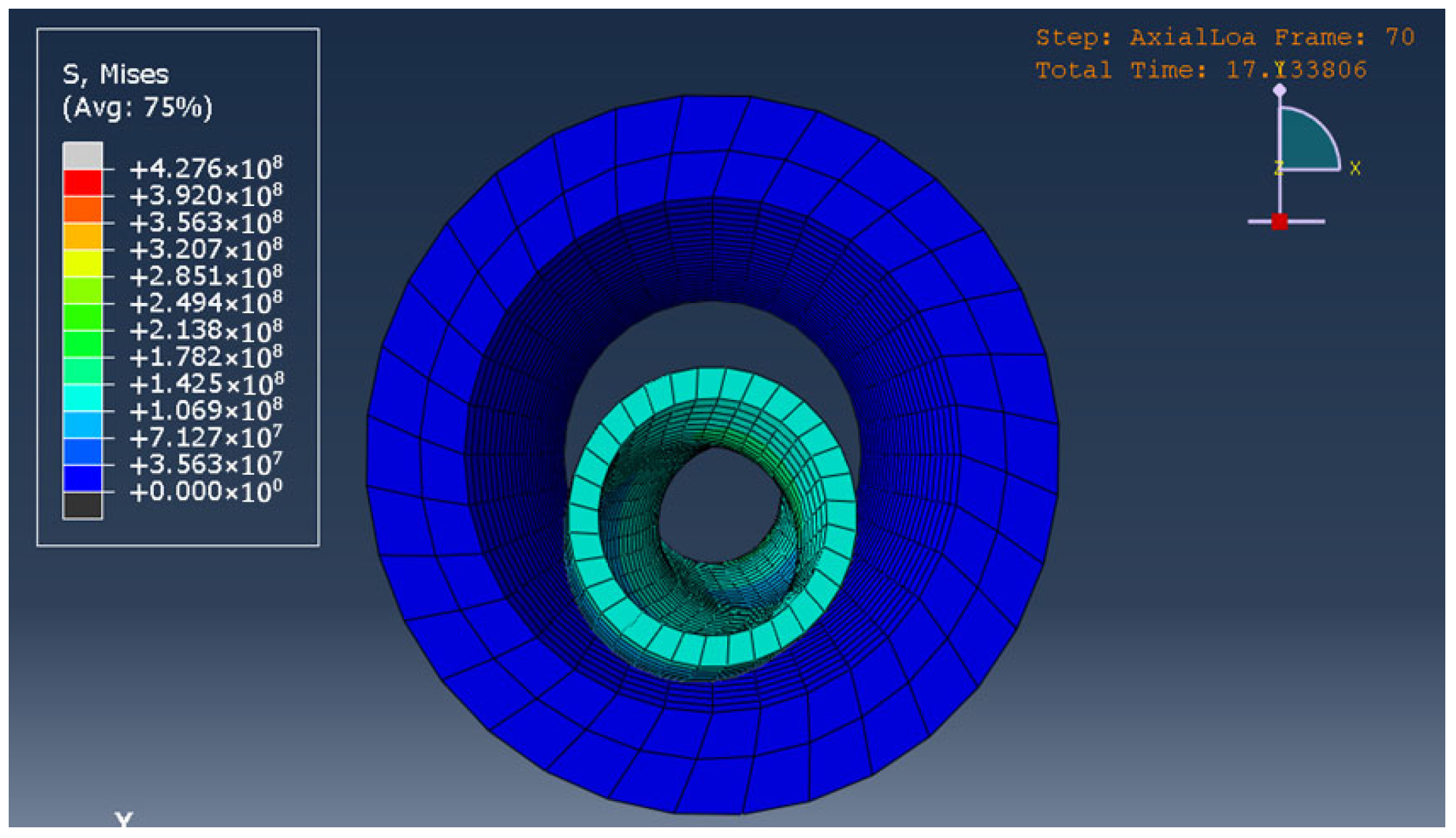
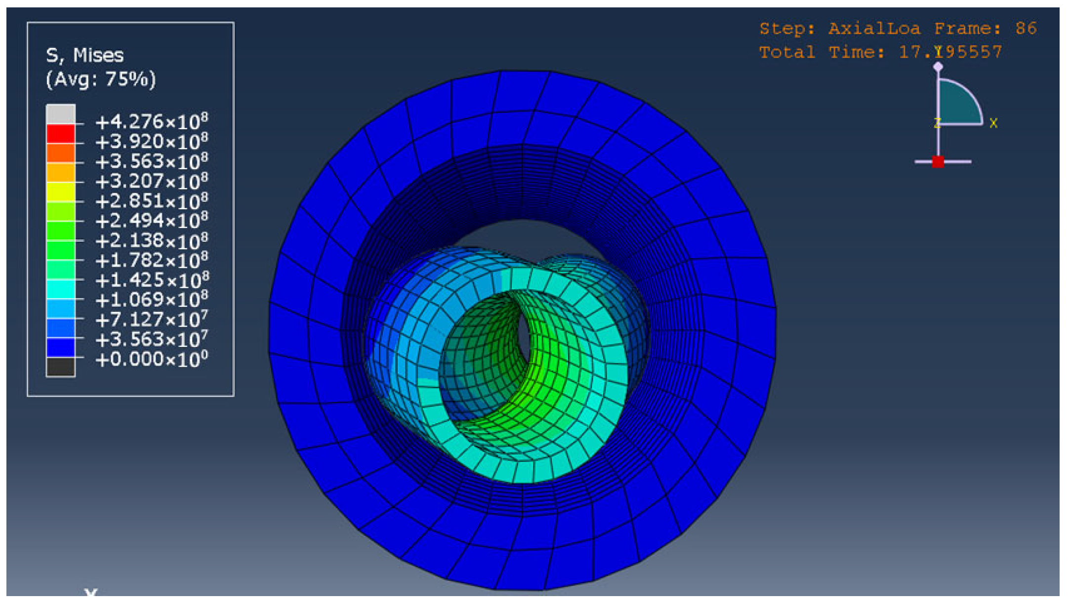
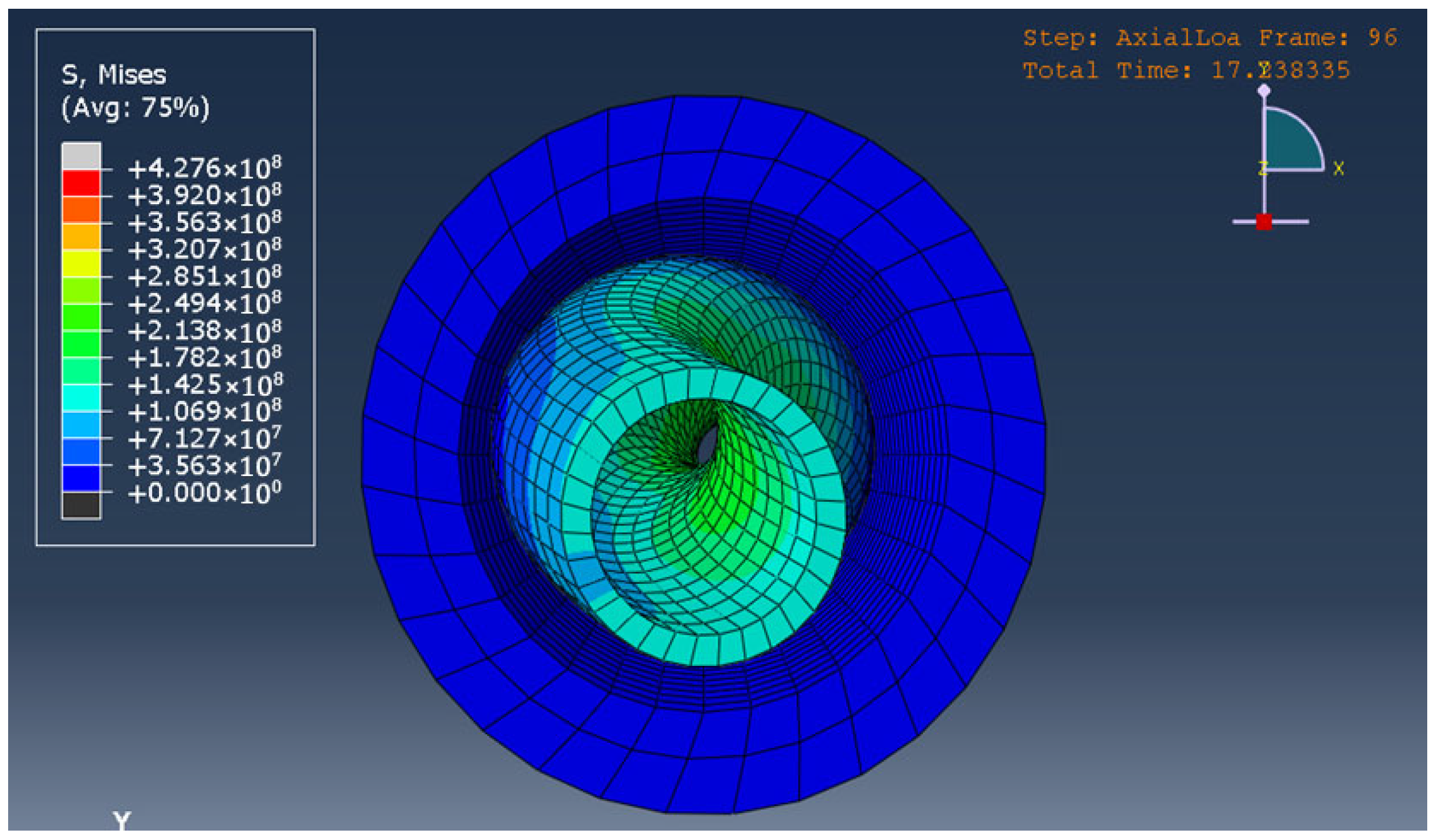
Figure 1 shows a graph of the dependence of the axial displacement of the end point of the drill pipe on time in a frictionless experiment. In the interval 17.13–17.14 s, a sharp jump in deformation is recorded which indicates buckling and a transition to another stable configuration. At this moment, the column experiences sinusoidal buckling, which subsequently transforms into a helical configuration, as clearly shown in Figure 2, Figure 3 and Figure 4. The critical load is 268 kN.
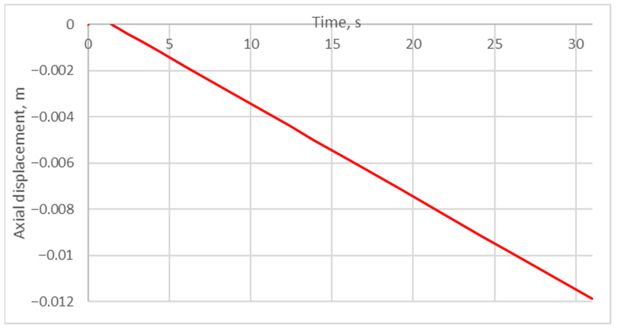
Figure 5 shows the displacement of the drill pipe’s end as a function of time in the experiment with friction. Linear deformation obeying Hooke’s law (Equation (14)) without buckling is observed, which indicates the stabilizing effect of friction between the drill string and the wellbore wall:
l = F a x L E A = 500000 · 12 2.1 · 10 11 · π 4 · 0.0889 2 0.0702 2 = 0.012225   m ,
where L is the length of the loaded section of the drill string; A is the cross-sectional area of the drill pipe.
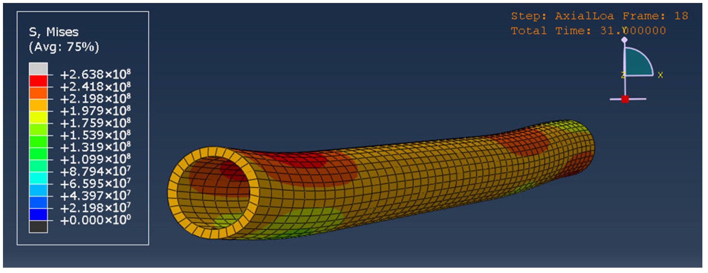
Figure 6 shows the deformation of the pipe at the end of the experiment. Particular attention should be paid to the deflection caused by the presence of tool joints, which creates bending stresses in the drill string and additional side force pressing it against the borehole wall.

3.2. Series of Experiments with Axial Vibrations Without Friction

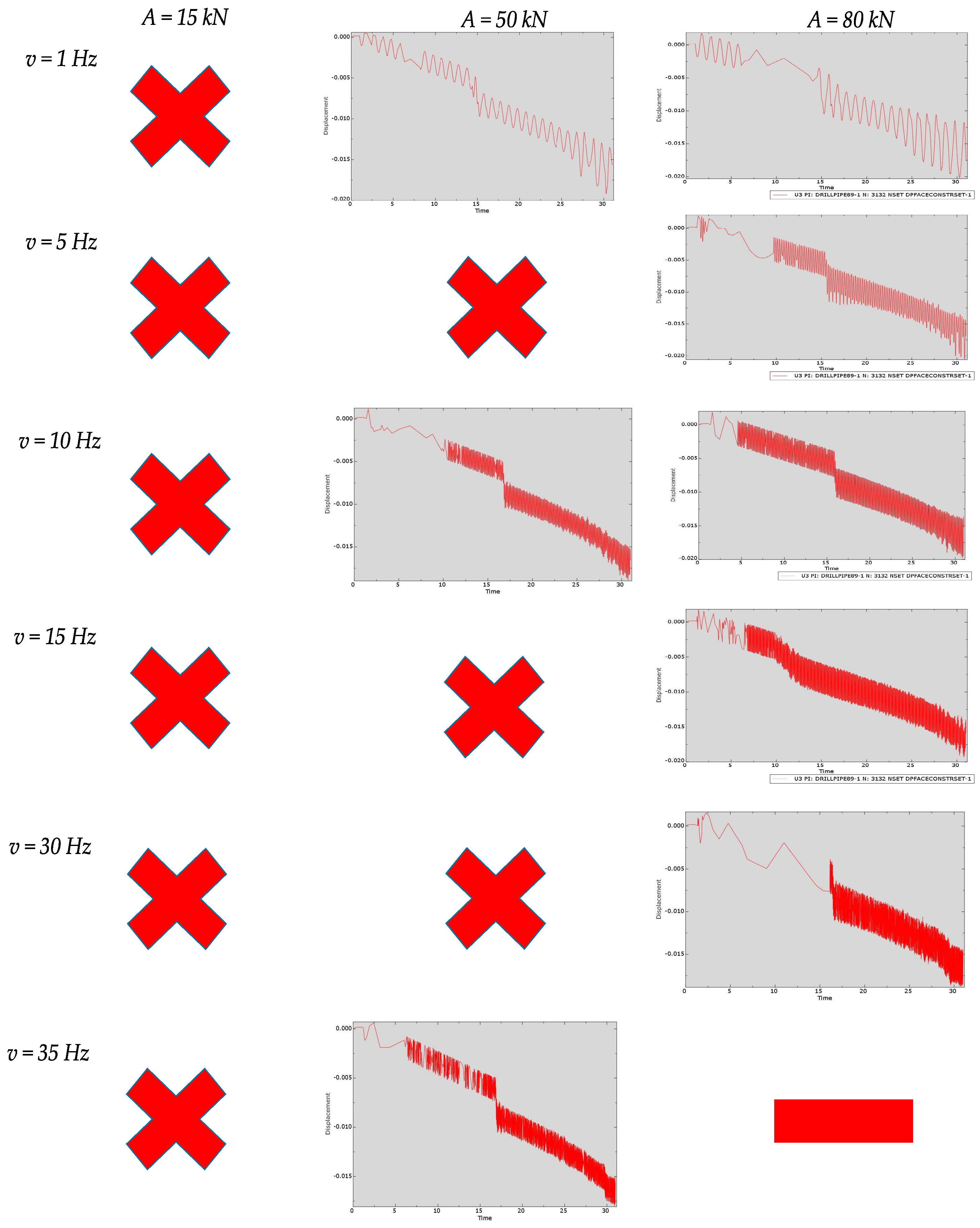
Figure 7 presents the conducted series of experiments. Experiments where no loss of stability occurs are marked with crosses. The calculation where no solution was obtained due to nonconvergence is marked with a dash, “-”. In experiments where buckling is observed, the critical load is lower than in the reference experiment. There is no clear correlation between the growth or decrease in the critical load depending on the frequency; fluctuations of the critical load are observed. The greatest decrease in critical load is observed under vibrations with an amplitude of 80 kN and a frequency of 15 Hz. This experiment also demonstrates that the transition to the helical configuration is not instantaneous, the sinusoidal buckling state is prolonged in time. The series of experiments show that there are frequency and amplitude ranges where either a stabilizing or destabilizing effect is observed.

3.3. Series of Experiments with Axial Vibrations with Friction

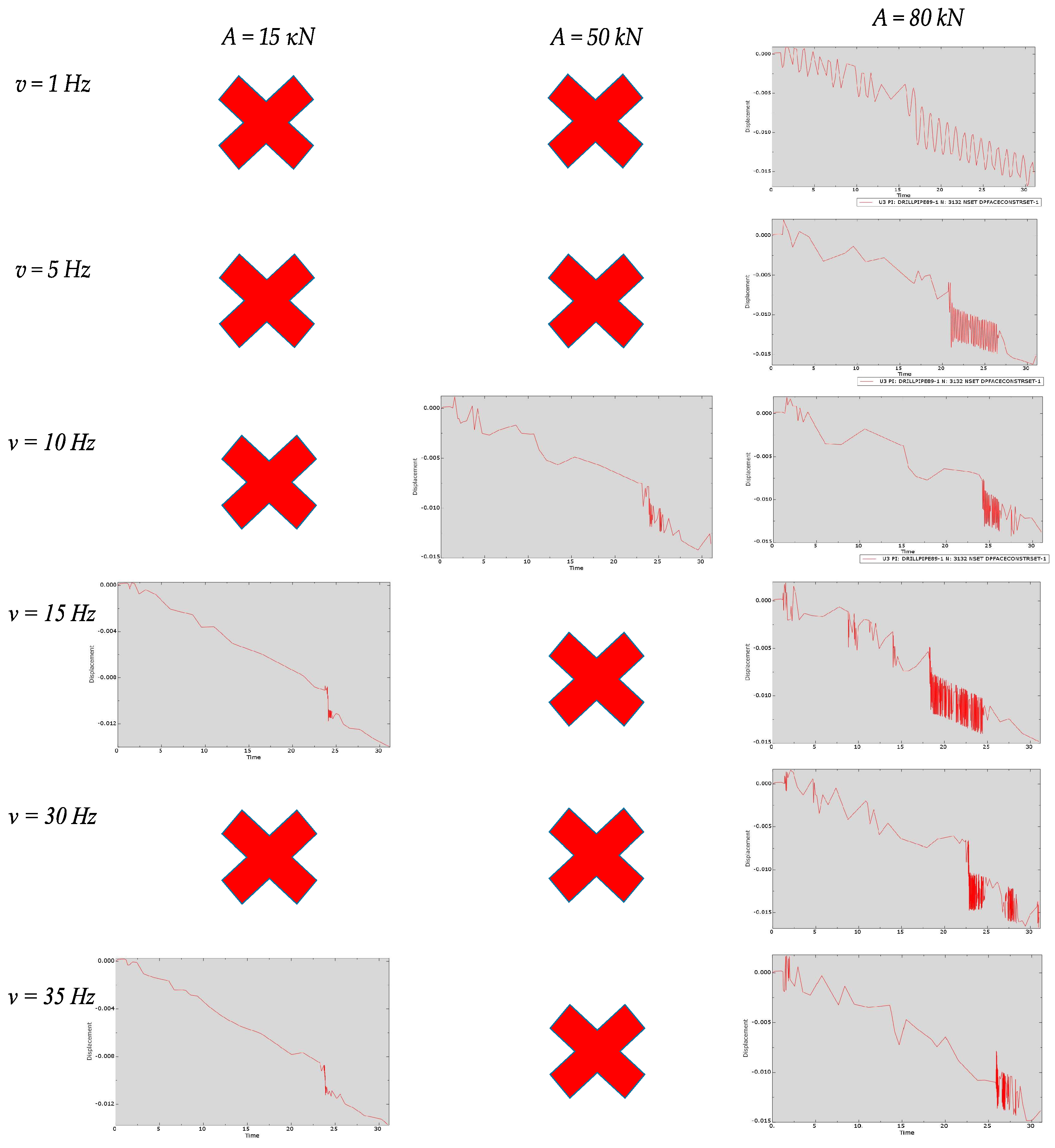
The conducted series of experiments is presented in Figure 8. At certain frequencies and amplitudes of vibration, buckling is observed, i.e., the vibrations negated the stabilizing effect of friction. In almost all experiments, except those where vibration levels of 1 Hz, 80 kN and 15 Hz, 80 kN were applied, the critical load was higher than in the reference experiment without friction. There is also no clear dependence of the critical load increase or decrease on the frequency; the critical load fluctuates. The greatest fluctuations of the critical load are observed at an amplitude of 80 kN.

3.4. Series of Experiments with Lateral Vibrations Along the OX-Axis Without Friction

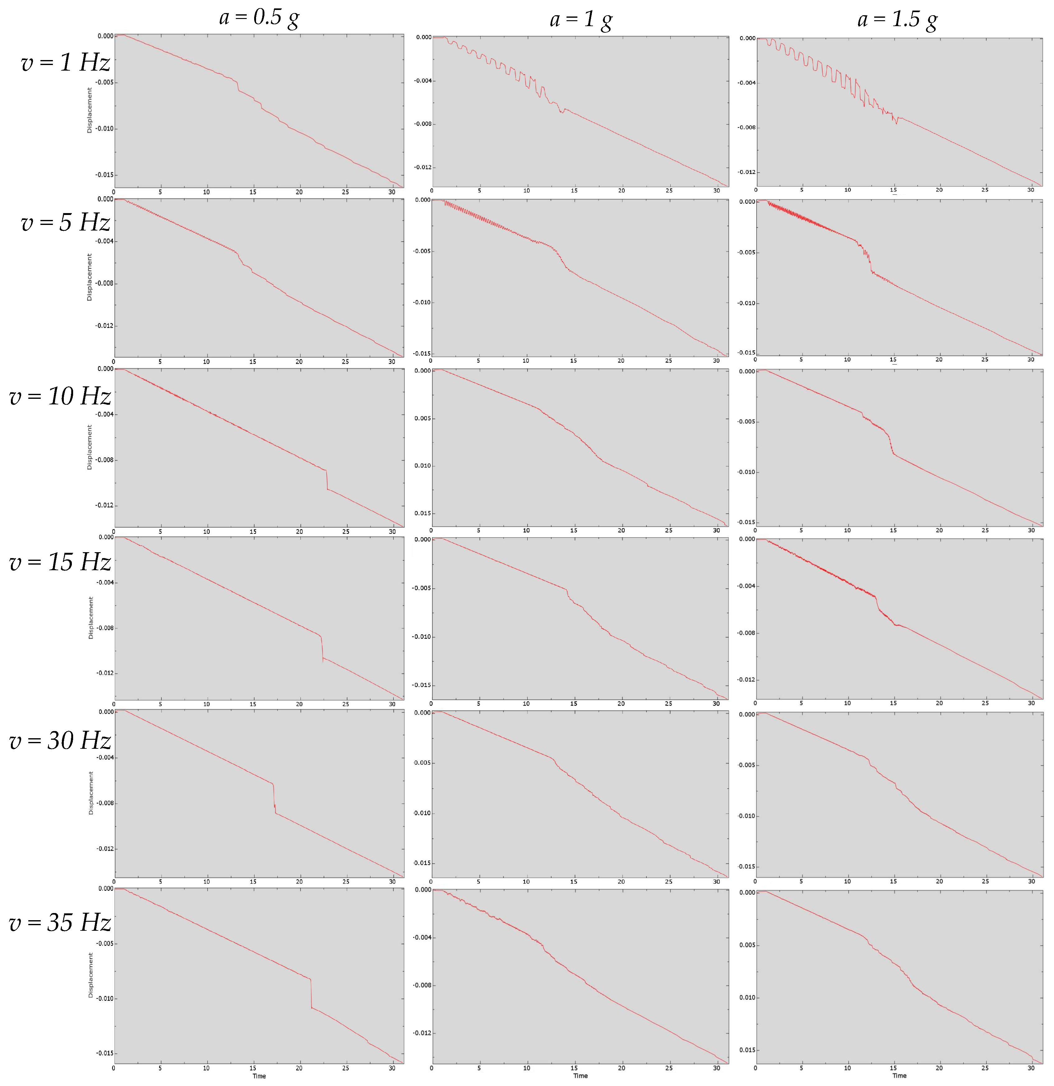
The series of experiments with lateral vibrations without friction is presented in Figure 9. In all experiments, the critical load is lower than in the reference experiment without friction. A systematic reduction in the critical load is observed with increasing vibration amplitude from 0.5 g to 1.5 g. This behavior can be explained by the growth of lateral deflection of the drill string, which leads to premature buckling. Similar to the case of axial vibrations, zones of stability and instability are observed, i.e., there is a fluctuation in the reduction in the critical load compared to the reference experiment. The lowest critical load is recorded at a vibration frequency of 1 Hz with amplitudes of 0.5 g and 1 g, and at 5 Hz with an amplitude of 1.5 g. Further, as the frequency increases to 15–35 Hz, the critical load increases and fluctuates slightly around a certain average value. It is important to note that the existence of the sinusoidal buckling state is prolonged in time, especially under low-frequency vibrations.

3.5. Series of Experiments with Lateral Vibrations Along the OX-Axis with Friction

The series of experiments with lateral vibrations with friction is presented in Figure 10. Unlike the series of experiments without friction, this set of experiments demonstrates pronounced fluctuations of the critical load. The vibrations are most pronounced at an acceleration amplitude of 0.5 g, decreasing and becoming relatively insignificant as the amplitude increases to 1.5 g. Variation in the vibration amplitude may also result in a frequency shift of instability zones. For example, a local unstable zone in the high-frequency range at a vibration amplitude of 0.5 g is observed at a frequency of 30 Hz, while at an amplitude of 1 g it is observed at a frequency of 35 Hz. Some combinations of vibration frequency and amplitude can lead to a significant reduction in critical load: despite the increase in vibration amplitude, the critical load at a frequency of 1 Hz and an amplitude of 1 g is less than the critical load in an experiment with a vibration frequency of 1 Hz and an amplitude of 1.5 g.

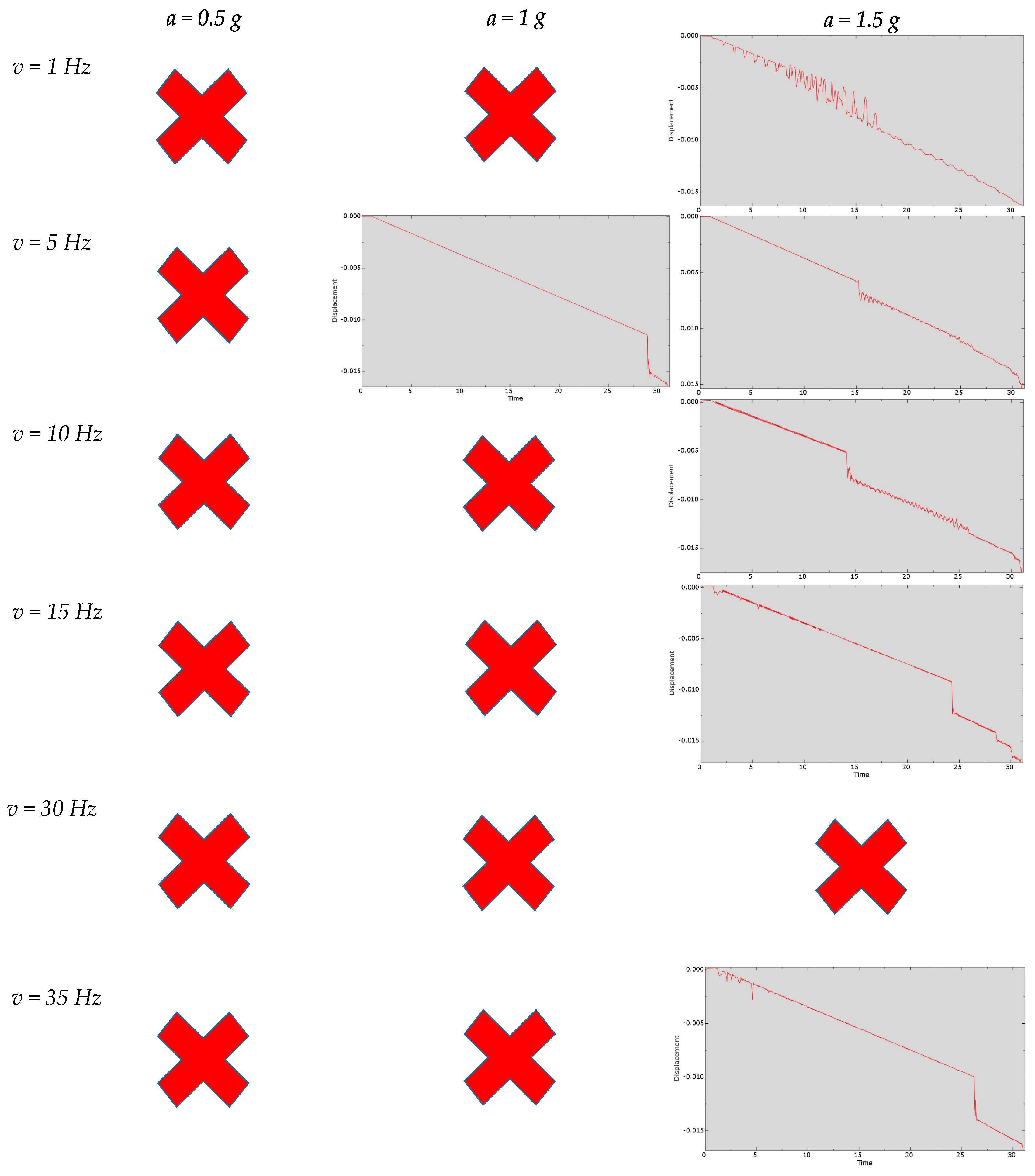
3.6. Series of Experiments with Lateral Vibrations Along the OY-Axis Without Friction

Figure 11 presents the series of experiments with vertical vibrations without friction. In almost all experiments with an acceleration amplitude of 0.5–1 g, no buckling is observed; at an amplitude of 1 g and a frequency of 5 Hz, the critical load is high. Buckling and a significant reduction in the critical load were observed at an amplitude of 1.5 g, which makes it possible to offset the stabilizing effect of gravity. The series also shows fluctuations in critical load and stability and instability zones, as in previous experiments.

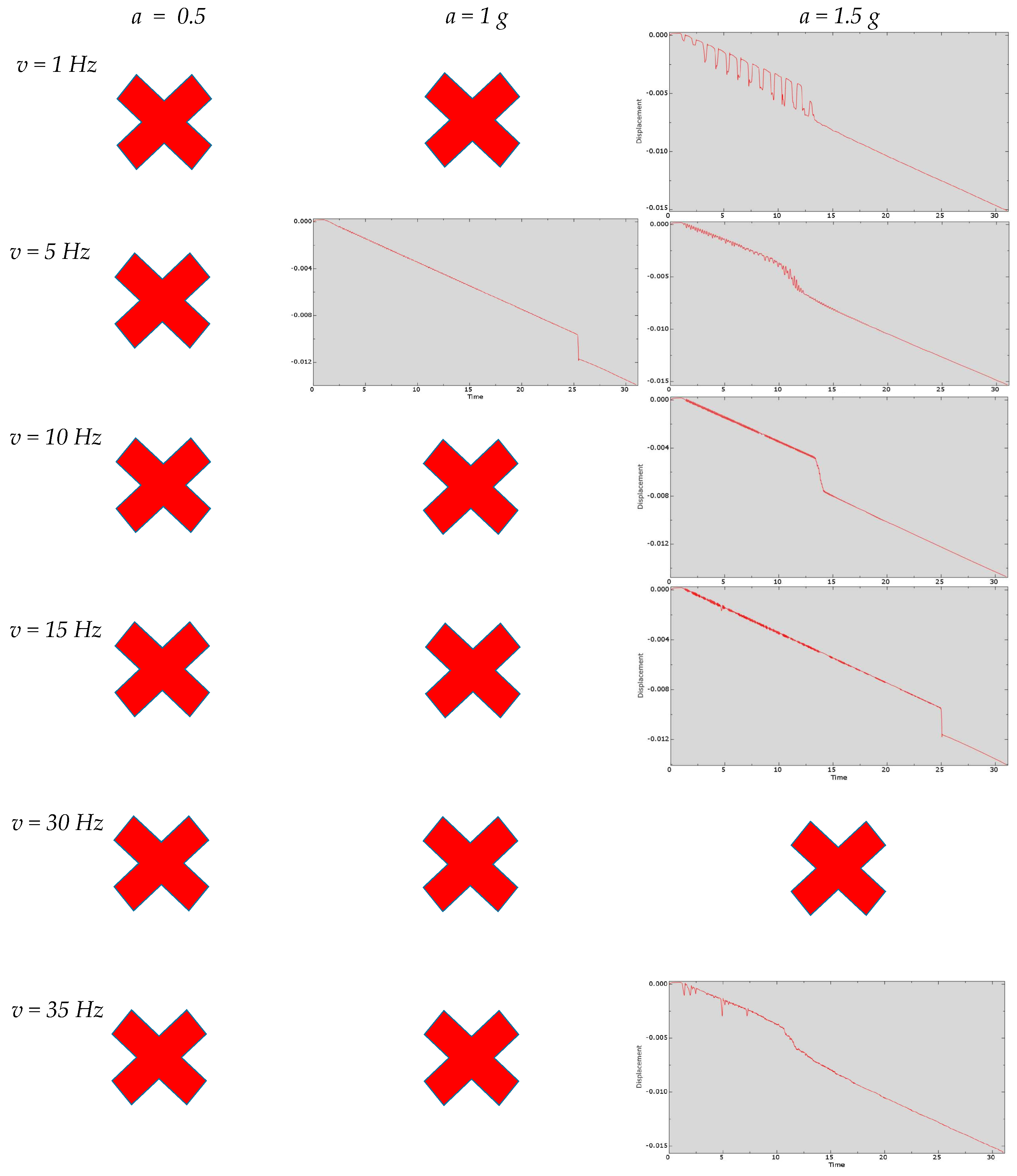
3.7. Series of Experiments with Lateral Vibrations Along the OY-Axis with Friction

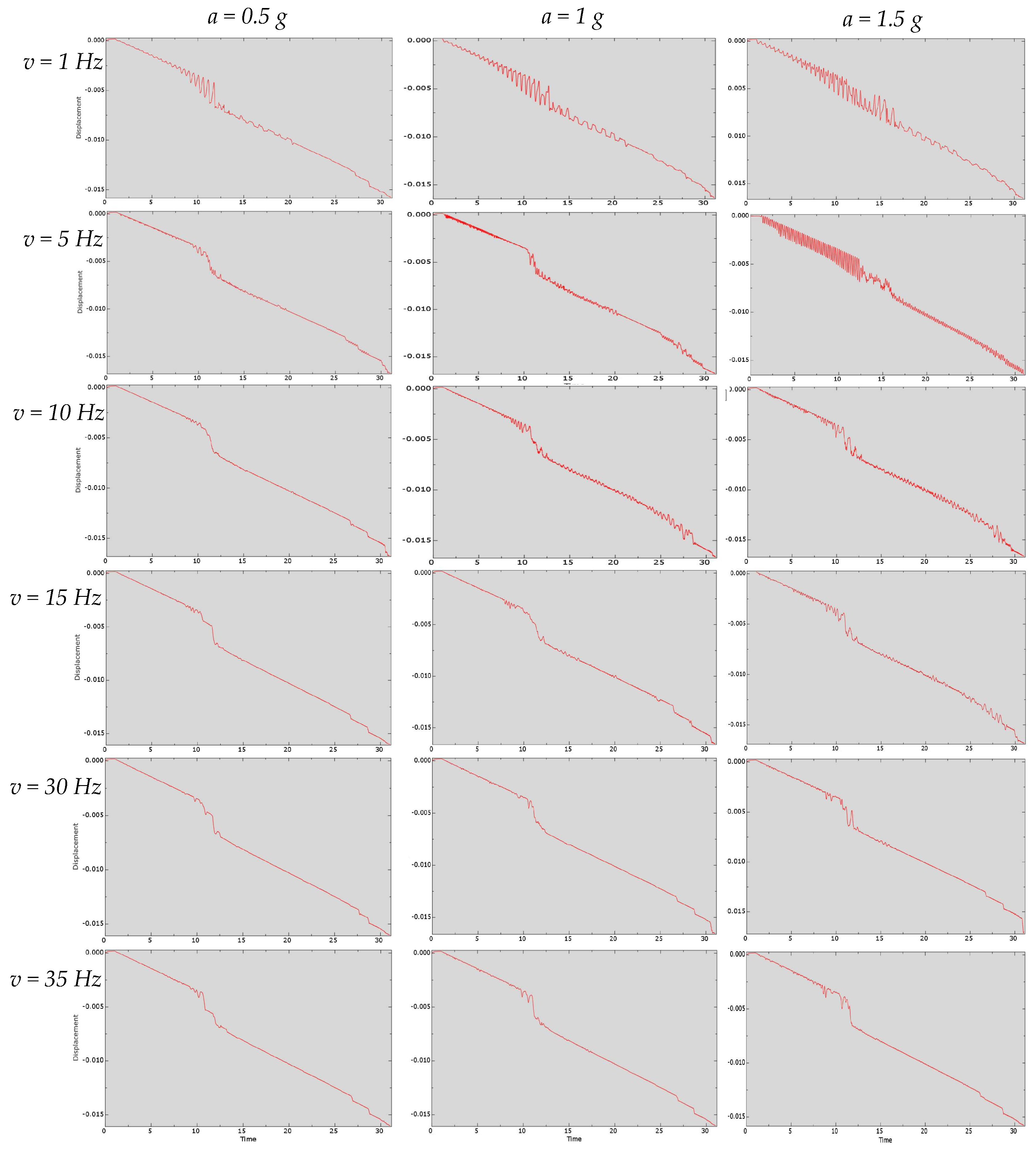
A series of experiments with vertical vibrations with friction is shown in Figure 12. As in the series of experiments without friction, no buckling is observed at a vibration amplitude of 0.5–1 g; the critical load is high at an amplitude of 1 g and a frequency of 5 Hz. The displacement curves of the drill pipe’s end under axial loading are smoother, as friction reduces the vibrations of the drill string in the post-buckling state. In almost all experiments a decrease in critical load is observed, which is paradoxical since the previous series show a stabilizing effect of friction. This phenomenon is presumably associated with a delayed upward movement of the drill string combined with a continuously increasing axial load, which leads to the formation of local areas with high stresses, allowing the column to exit the state of equilibrium.

4. Discussion

The influence of dynamic conditions shows, at first glance, an unobvious effect on the critical load and the post-buckling state of the drill string. Various combinations of vibration frequency and amplitude can have both destabilizing and stabilizing effects. This behavior is explained by the Strutt–Ince diagram, the solution of the Mathieu equation. Lubkin and Stoker, by solving the Mathieu equation (Formula (15)), demonstrated that there exist combinations of system parameters—the magnitude of the constant axial load, the amplitude of the variable axial load, stiffness, length, and the frequency of the axial force oscillation—at which buckling is possible even if the constant component of the axial load is less than the expected critical load under static loading and, conversely, it is possible to maintain the “straight” form of stability even if the static component exceeds the critical load [42].
d 2 F a x d v 2 + α + β cos v F a x = 0 ,
where v = 2 π f t ; f—oscillation frequency; t—time; α ,     β —parameters depending on the frequency of the oscillating component of the force F a x , the magnitudes of the applied loads, the geometry of the loaded string, and the material properties of the string; F a x t = P + H cos 2 π f t ; P—constant component of the axial load; H—amplitude of the variable axial load.
The approach presented in this article differs from the problem formulation in the study by Lubkin and Stoker in that instead of a constant axial load P, a constantly increasing force is applied, i.e., F a x t = a t + H cos 2 π f t ; in experiments, a = 500,000/30 ≈ 16,667 N/s. This approach is closer to the actual process of loading a rock-breaking tool or adjusting the axial load during drilling. The effect of not only variable axial load but also lateral vibrations on the buckling of the downhole assembly was also considered. The experiments show that both variable axial load and lateral vibrations, depending on the internal parameters of the system, can have either a destabilizing or a stabilizing effect. Stabilization of the drill string improves axial load transfer, which allows reconsideration of the use of downhole vibrators or drilling control strategies that involve not avoiding vibrations, but selecting the frequencies and amplitudes of vibrations that ensure the maximum possible drilling efficiency.
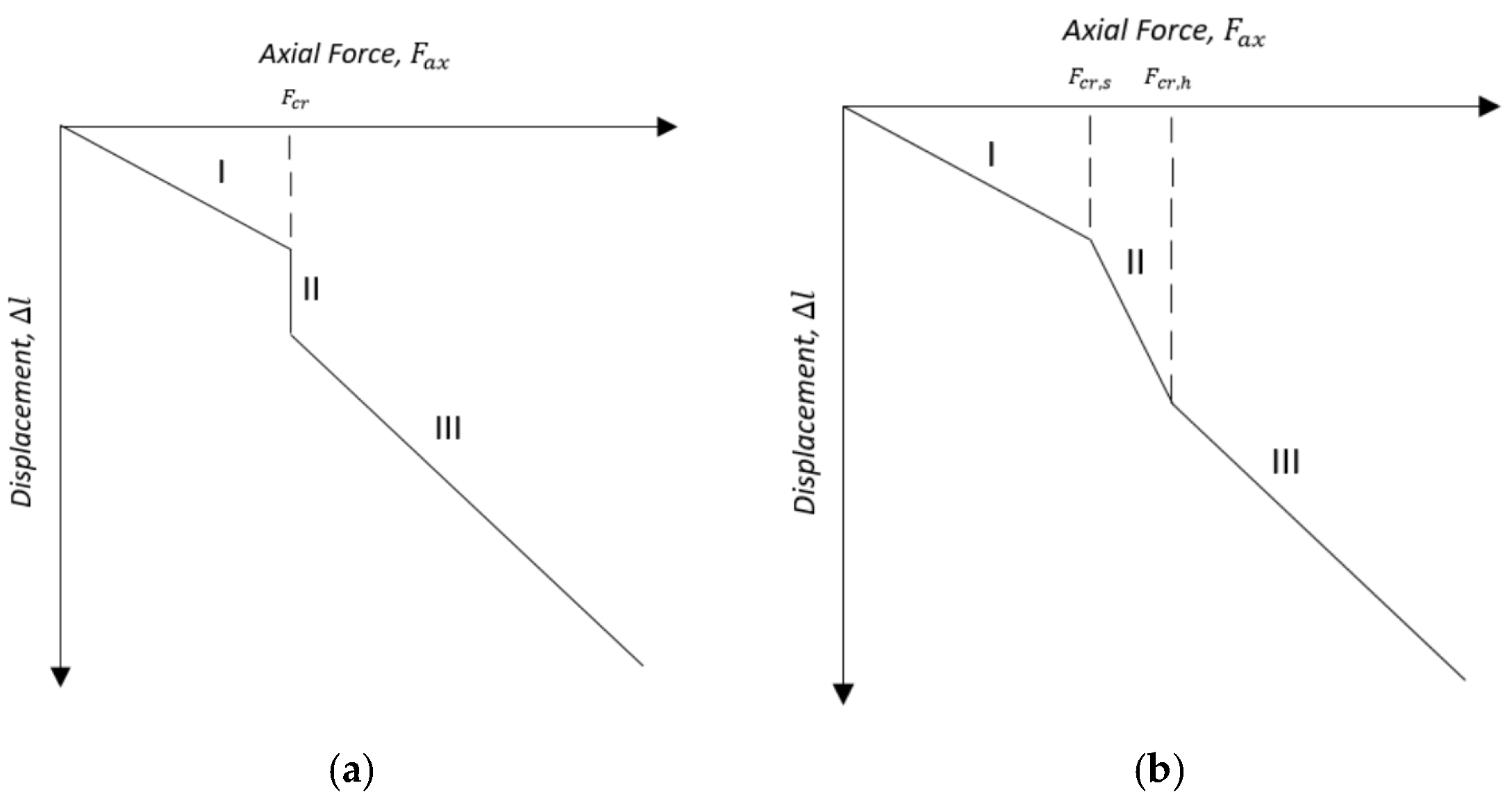
The study shows that the difficult-to-predict effects of friction, dynamic conditions, and the presence of tool joints on the loss of stability of downhole assemblies cannot be ignored, which confirms the necessity of employing accurate monitoring systems capable of detecting the onset of buckling. Despite the complex influence of various factors on the change in critical load and the behavior of the drill string in a post-critical state, certain patterns of end displacement can be identified, i.e., deformation of the column in a state of sinusoidal or helical buckling, represented in Inequality (16), and the process of column deformation can be reduced to two schemes shown in Figure 13.
d l 2 d F a x d l 3 d F a x > d l 1 d F a x ,
where d l 1 is the deformation of the section of the tool that retains a “straight” form of stability, d l 2 is the deformation of the section in sinusoidal buckling, and d l 3 is the deformation of the section in helical buckling.
The acceleration of deformation in the buckled state is explained by the fact that, in addition to the linear deformation described by Hooke’s law, the tool section is also subjected to axial deformation resulting from the formation of longitudinal bending, as represented in Expression (17):
l = F a x L E A + l b u c k l ,
where the deformation from bending in the helical buckling state can be calculated using Formula (18) [50]:
l b u c k l = 2 π 2 r 2 L p h 2 ,
where Formula (4) can be used to determine the pitch of the helix p h , or, if Formula (4) is substituted into Formula (18), Expression (19) can be obtained to determine the axial deformation of a buckled string directly from the force:
l b u c k l = F a x r 2 L 4 E I .
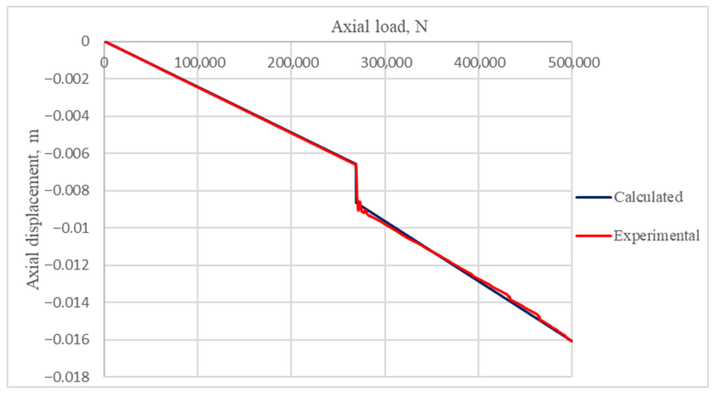
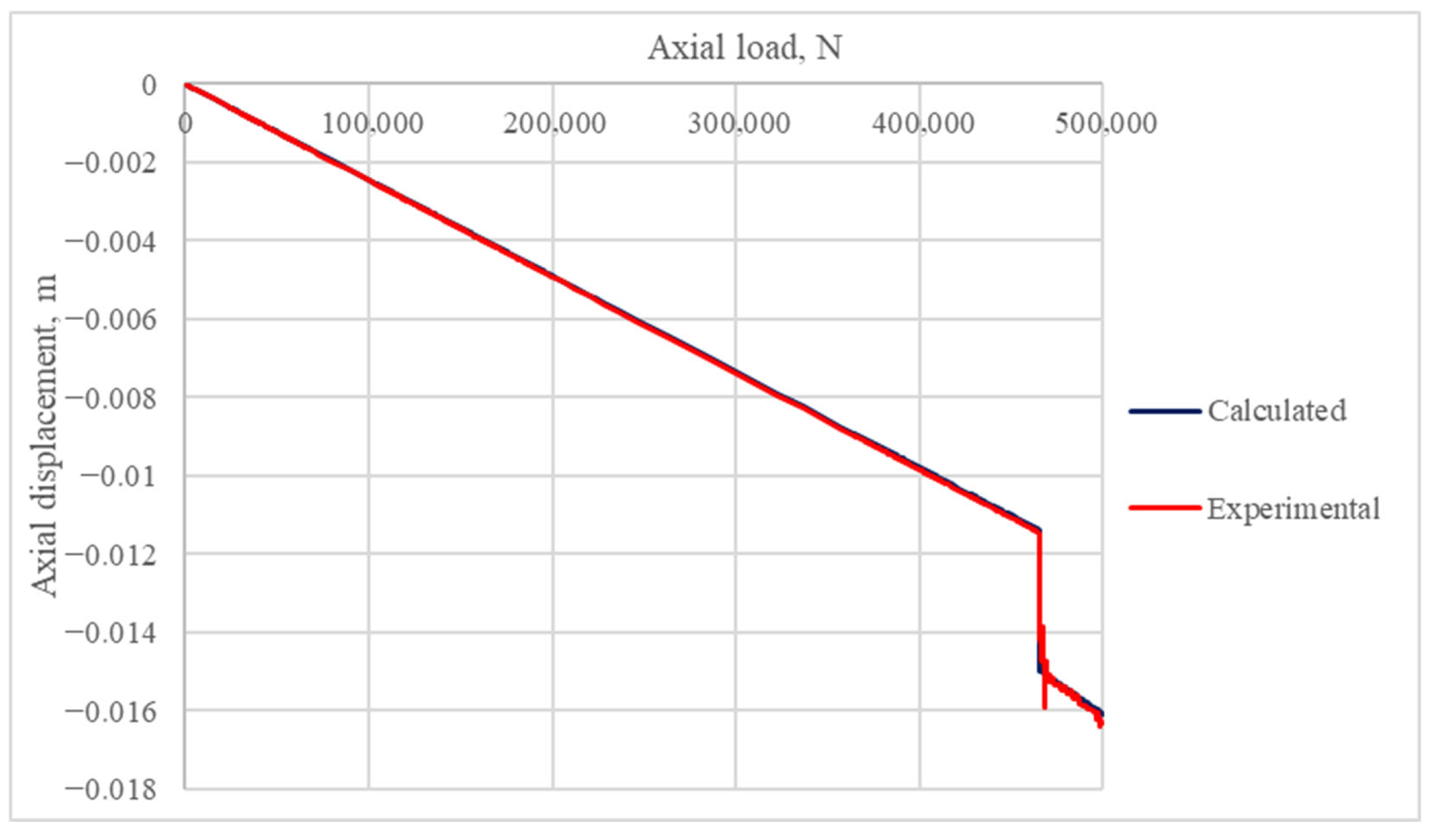
A comparison of the displacement values obtained during the experiments—the reference without friction and with vertical vibrations at a frequency of 5 Hz with an amplitude of 1 g without friction—with the calculated values is shown in Figure 14 and Figure 15, respectively. The deformation caused by the deflection of the column due to gravity, which occurred during the first second of the experiment, is eliminated in the graphs in order to analyze only the deformation caused by the axial load.
As can be seen in the graphs, Formulae (16)–(19) accurately predict the deformation of the drill string in a post-critical state.
Expression (16) can be used as a criterion for identifying buckling. By tracking the hook load and the speed of the traveling block, which is the sum of the displacement from drill string deformation and drilling penetration, performing continuous simulations of axial force distribution and torque on the downhole assembly with simultaneous calculation of column deformation, it is possible to determine the location of longitudinal bending and, as a result, accurately calculate the SSS of the DS.
This approach can be implemented in modern monitoring and automatic control systems of drilling rigs. The traveling block speed is measured by a sensor that records the rotational speed and direction of the drawworks or the crown block sheave. The hook load is measured either by a sensor installed on the dead line of the hoisting system or by a sensor mounted directly on the traveling block or the top drive— the latter option provides higher accuracy. The sampling rate of continuous recording of the traveling block speed and hook load in modern data acquisition and display systems is ≥1 Hz, which enables real-time calculation of the current and predicted stress–strain state of the drill string.
An additional criterion for buckling could hypothetically be a shock incident from a sharp displacement, d l d F = , as shown in diagram (a) in Figure 13, indicating the formation of helical buckling or an increase in vibrations, indicating that the column is in a state of sinusoidal buckling. The detection of such vibrations, as a consequence of drill string instability, is feasible through the accelerometer incorporated in the M/LWD system. Tracking shocks during the bit loading process with the calculation of the shock wave propagation time from the epicenter of stability loss to the bottomhole accelerometer can increase the accuracy of localizing the section with buckling.
Identification of the critical and post-critical states of the drill string will make it possible to verify the actual sinusoidal and helical buckling critical loads, which will correspond to certain values of hook load and weight on the bit during loading. The identified hook load and weight on the bit thresholds should not be exceeded during further drilling operations in order to maintain the stable state of the drill string.

5. Conclusions

Based on the analysis of the results of the computational experiments, the following conclusions can be drawn:
  • It has been demonstrated that frictional forces exert a stabilizing effect on the drill string, and the influence of friction effect cannot be neglected when predicting critical loads.
  • The presence of tool joints may exert a stabilizing effect due to the formation of an additional contact force from the deflection of the string and the formation of bending stresses in the tool body.
  • The influence of vibrations on the buckling behavior of the drill string has been refined. Different combinations of vibration frequency and amplitude of the acting force form zones of stability and instability. In zones of instability, the critical load is significantly reduced, while in zones of stability the reduction in critical load is relatively small or there is an increase in critical load compared to the value predicted in the static formulation of the problem. The presence of stability zones allows us to reconsider the drilling technology from the point of view of not avoiding vibrations, but selecting the frequency of vibrations and the amplitude of the variable acting force, which are inevitably formed during the drilling process, in order to increase the efficiency of drilling. The use of vibrators to stabilize the drill string may be expedient.
  • Lateral vibrations in a plane perpendicular to the vertical reduce the critical load by forming eccentricity, which facilitates the drill string losing its equilibrium. An increase in the amplitude of vibrations generally leads to a decrease in the critical load, but certain combinations of amplitude and frequency of vibrations can lead to localized zones of stabilization and significant destabilization.
  • Lateral vibrations aligned with the vertical may negate the stabilizing effect of drill string bending caused by gravity and tool joints when the vibration amplitude is >1 g. Certain frequencies, for example 5 Hz in the series of experiments conducted, can destabilize the drill string at an amplitude of 1 g. Certain frequencies, for example 30 Hz, contribute to significant stabilization of the column even at an amplitude of 1.5 g.
  • It has been established that the rate of deformation of the column in a state of sinusoidal buckling from axial loading is many times greater than the rate of deformation according to Hooke’s law and deformation in a helical form. The deformation of the drill string in a helical buckling state is greater than the deformation of a “straight” drill string obeying Hooke’s law. These deformation rate relationships are also observed under dynamic conditions.
  • The possibility of identifying and localizing drill string buckling by monitoring traveling block velocity and hook load has been theoretically substantiated and experimentally confirmed. Tracking shocks using downhole accelerometers may improve the accuracy of localizing sections of the drill string that are in a state of buckling. After identifying and localizing the loss of stability, the analytical model should use appropriate formulae for calculating additional side force against the wellbore wall, bending moment, and bending stresses, in order to enhance the accuracy of determining the DS SSS and fatigue wear in the post-buckling state.
  • It has been revealed that a column in a state of sinusoidal bending, due to its unstable state, is susceptible to vibrations; therefore, it is recommended to avoid maintaining the drill string in a sinusoidal buckling configuration to prevent wear of the string and tool from multicycle fatigue from vibrations during “sliding” and column rotation, when alternating bending loads occur.
  • In future studies, it is necessary to investigate the influence of drill string rotation, including the development of precessional motion and torsional vibrations, as well as to clarify the combined effects of dynamic conditions and the presence of the downhole tool in the drilling fluid environment on the buckling of the drill string.

Author Contributions

Conceptualization, M.D. and P.K.; methodology, P.K.; software, P.K.; validation, P.K.; formal analysis, P.K.; investigation, P.K.; resources, M.D.; data curation, P.K.; writing—original draft preparation, P.K.; writing—review and editing, M.D.; visualization, P.K.; supervision, M.D. All authors have read and agreed to the published version of the manuscript.

Funding

The work was carried out within the state assignment of the Ministry of Science and Higher Education of the Russian Federation (FSRW-2023-0002 Fundamental interdisciplinary studies of the Earth’s interior and processes of integrated development of georesources).

Institutional Review Board Statement

Not applicable.

Informed Consent Statement

Not applicable.

Data Availability Statement

The original contributions presented in this study are included in the article. Further inquiries can be directed to the corresponding author.

Conflicts of Interest

The authors declare no conflicts of interest.

Abbreviations

The following abbreviations are used in this manuscript:
SSSStress–strain state
DSDrill string
M/LWDMeasurements/logging while drilling
BHABottomhole assembly

References

  1. Litvinenko, V. The Role of Hydrocarbons in the Global Energy Agenda: The Focus on Liquefied Natural Gas. Resources 2020, 9, 59. [Google Scholar] [CrossRef]
  2. Morenov, V.A.; Shchigolev, K.V. Assessment of the Possibility of Carbon Dioxide Utilization for Enhanced Oil Recovery in Oil Field Condition. Neftyanoe Khozyaystvo—Oil Ind. 2025, 4, 76–81. [Google Scholar] [CrossRef]
  3. Nikolaev, A.; Zhukov, A.; Goluntsov, A.; Shirmaher, E. Evaluation of the Effectiveness of Anti-Turbulence Additives in the Transportation of High-Viscosity Oil at Low Ambient Temperatures. Processes 2025, 13, 1434. [Google Scholar] [CrossRef]
  4. Wang, F.; Kobina, F. The Influence of Geological Factors and Transmission Fluids on the Exploitation of Reservoir Geothermal Resources: Factor Discussion and Mechanism Analysis. Reserv. Sci. 2025, 1, 3–18. [Google Scholar] [CrossRef]
  5. Savenok, O.V.; Zharikova, N.K.; Chuykova, E.P.; Verisokin, A.E.; Hadid, M.; Povarova, L.V.; Kalashnikov, D.S.; Domanova, A.S. Justification and Selection of a Method for Restricting Water Inflow to Horizontal Wells in Low-Permeability Terrigenous Reservoir Conditions Using the Example of the YuS2 Formation of an Oil and Gas Condensate Field. Bull. Tomsk. Polytech. Univ. Geo Assets Eng. 2025, 336, 193–205. [Google Scholar] [CrossRef]
  6. Wu, J.; Ansari, U. From CO2 Sequestration to Hydrogen Storage: Further Utilization of Depleted Gas Reservoirs. Reserv. Sci. 2025, 1, 19–35. [Google Scholar] [CrossRef]
  7. Blinov, P.A.; Silichev, N.M.; Nikishin, V.V.; Gorelikov, V.G. Justification and Development of a Continuous Deflector with Full Core Sampling for Drilling Exploration Wells. Bull. Tomsk Polytech. Univ. Geo Assets Eng. 2025, 336, 17–28. [Google Scholar] [CrossRef]
  8. Zhdaneev, O.V.; Zaytsev, A.V.; Prodan, T. Possibilities for Creating Russian High-Tech Bottomhole Assembly. J. Min. Inst. 2021, 252, 872–884. [Google Scholar] [CrossRef]
  9. Blinov, P.A.; Sadykov, M.I.; Gorelikov, V.G.; Nikishin, V.V. Development and Research of Backfill Compounds with Improved Elastic and Strength Properties for Oil and Gas Well Lining. J. Min. Inst. 2024, 268, 588–598. [Google Scholar]
  10. Bolshunov, A.V.; Ignatev, S.A.; Serbin, D.V.; Turkeev, A.V. Experimental Ice Drilling with Organosilicon Fluid Using the KEMS-135 Drill in Borehole 5G (Vostok Station, Antarctica). J. Min. Inst. 2025, 273, 147–158. [Google Scholar]
  11. Serbin, D.V.; Buslaev, G.V.; Lavrik, A.Y.; Kadochnikov, V.G.; Dmitriev, A.N. Study of the Interaction between the Drilling Fluid and Lake Water during the Opening of the Subglacial Lake Vostok in Antarctica. J. Min. Inst. 2025, 273, 136–146. [Google Scholar]
  12. Buslaev, G.V.; Konoplyannikov, A.V. Mathematical Modeling of a Hydro-Mechanical System with a Positive Displacement Motor and Hydraulic Thruster to Optimize the Drilling Process for Extended-Reach Drilling Wells. Int. J. Eng. Trans. B Appl. 2026, 39, 1077–1087. [Google Scholar] [CrossRef]
  13. Griguletsky, V.G.; Kuznetsov, A.B. Influence of Bit Size on Stability Bottom Drill Column Balance When Drilling a Horizontal Well. Oil Gas Stud. 2021, 3, 37–51. [Google Scholar] [CrossRef]
  14. Cunha, J.C. Buckling of Tubulars inside Wellbores: A Review on Recent Theoretical and Experimental Works. SPE Drill. Complet. 2004, 19, 13–19. [Google Scholar] [CrossRef]
  15. Lubinski, A.; Althouse, W.S. Helical Buckling of Tubing Sealed in Packers. J. Pet. Technol. 1962, 14, 655–670. [Google Scholar] [CrossRef]
  16. Wang, C.Y. A Critical Review of the Heavy Elastica. Int. J. Mech. Sci. 1986, 28, 549–559. [Google Scholar] [CrossRef]
  17. Wu, J.; Juvkam-Wold, H.C. Buckling and Lockup of Tubulars in Inclined Wellbores. J. Energy Resour. Technol. 1995, 117, 208–213. [Google Scholar] [CrossRef]
  18. Paslay, P.R.; Bogy, D.B. The Stability of a Circular Rod Laterally Constrained to Be in Contact with an Inclined Circular Cylinder. J. Appl. Mech. 1964, 31, 605–610. [Google Scholar] [CrossRef]
  19. Dawson, R.; Rapier, J. Drill Pipe Buckling in Inclined Holes. J. Pet. Technol. 1984, 36, 1734–1738. [Google Scholar] [CrossRef]
  20. McCann, R.C.; Suryanarayana, P.V.R. Experimental Study of Curvature and Frictional Effects on Buckling. In Proceedings of the Annual Offshore Technology Conference, Houston, TX, USA, 2–5 May 1994; pp. 511–521. [Google Scholar] [CrossRef]
  21. Miska, S.; Qiu, W.; Volk, L.; Cunha, J.C. An Improved Analysis of Axial Force along Coiled Tubing in Inclined/Horizontal Wellbores. In Proceedings of the SPE Eastern Regional Meeting, Morgantown, WV, USA, 23–25 October 1996; pp. 207–214. [Google Scholar] [CrossRef]
  22. Wu, J.; Juvkam-Wold, H.C. Coiled Tubing Buckling Implication in Drilling and Completing Horizontal Wells. SPE Drill. Complet. 1995, 10, 16–21. [Google Scholar] [CrossRef]
  23. Johancsik, C.A.; Friesen, D.B.; Dawson, R. Torque and Drag in Directional Wells—Prediction and Measurement. J. Pet. Technol. 1984, 36, 987–992. [Google Scholar] [CrossRef]
  24. He, X.; Kyllingstad, A. Helical Buckling and Lock-Up Conditions for Coiled Tubing in Curved Wells. SPE Drill. Complet. 1995, 10, 10–15. [Google Scholar] [CrossRef]
  25. American Petroleum Institute. API Recommended Practice 7G: Recommended Practice for Drill Stem Design and Operating Limits, 16th ed.; API: Washington, DC, USA, 1998. [Google Scholar]
  26. Qiu, W.; Miska, S.; Volk, L. Drill Pipe/Coiled Tubing Buckling Analysis in a Hole of Constant Curvature. In Proceedings of the Permian Basin Oil & Gas Recovery Conference, Midland, TX, USA, 23–25 March 1998; pp. 385–389. [Google Scholar] [CrossRef]
  27. Mitchell, S.; Moore, N.B.; Franks, J.; Liu, G.; Xiang, Y. Comparing the Results of a Full-Scale Buckling-Test Program to Actual Well Data: New Semiempirical Buckling Model and Methods of Reducing Buckling Effects. SPE Drill. Complet. 2011, 26, 578–596. [Google Scholar] [CrossRef]
  28. Mitchell, R.F.; Weltzin, T. Lateral Buckling—The Key to Lockup. SPE Drill. Complet. 2011, 26, 436–452. [Google Scholar] [CrossRef]
  29. Wu, J. Slack-Off Load Transmission in Horizontal and Inclined Wells. In Proceedings of the SPE Production Operations Symposium, Oklahoma City, OK, USA, 2–4 April 1995. [Google Scholar] [CrossRef]
  30. Kuru, E.; Martinez, A.; Miska, S.; Qiu, W. The Buckling Behavior of Pipes and Its Influence on the Axial Force Transfer in Directional Wells. J. Energy Resour. Technol. 2000, 122, 129–135. [Google Scholar] [CrossRef]
  31. Liang, Z.; Zhu, Z.L. Critical Helical Buckling Load Assessment of Coiled Tubing under Axial Force by Use of the Explicit Finite-Element Method. J. Pet. Sci. Eng. 2018, 169, 51–57. [Google Scholar] [CrossRef]
  32. Tan, X.C.; Forsman, B. Buckling of Slender String in Cylindrical Tube under Axial Load: Experiments and Theoretical Analysis. Exp. Mech. 1995, 35, 55–60. [Google Scholar] [CrossRef]
  33. Kuang, Y.; Li, B.; Liu, J.; Lu, H. Research on Buckling Behavior and Analysis of Sensitive Factors in Horizontal Well Drilling. J. Fail. Anal. Prev. 2016, 16, 376–383. [Google Scholar] [CrossRef]
  34. Wu, L.; Fang, P.; Huang, Y.; Li, G.; Xu, J. Study on the Evolution of Buckling Behavior of Tubular String under Frictional Effects in Horizontal Wells. J. Vibroeng. 2024, 26, 961–982. [Google Scholar] [CrossRef]
  35. Gao, G.; Miska, S. Effects of Friction on Post-Buckling Behavior and Axial Load Transfer in a Horizontal Well. SPE J. 2010, 15, 1110–1124. [Google Scholar] [CrossRef]
  36. Dunayevsky, V.A.; Abbassian, F.; Judzis, A. Dynamic Stability of Drillstrings under Fluctuating Weight on Bit. SPE Drill. Complet. 1993, 8, 84–92. [Google Scholar] [CrossRef]
  37. Jia, P.; Zhou, B.; Xue, S.; Zhang, Y.; Zhu, X.; Sun, F. A Dynamic Method for Post Buckling Analysis of Drill String in Vertical Wells. J. Pet. Sci. Eng. 2022, 214, 110334. [Google Scholar] [CrossRef]
  38. Tian, J.; Liu, C.; Yang, Y. Dynamic Buckling Characteristics of Drill String in Inclined Straight Well with Friction Effect. Int. J. Struct. Stab. Dyn. 2022, 23, 2350007. [Google Scholar] [CrossRef]
  39. Ren, F.; Wang, B.; Zhao, L.; Zhu, A. Experimental Investigation and Analysis of Dynamic Buckling of Drill String in Horizontal Well. Shock Vib. 2017, 2017, 1658435. [Google Scholar] [CrossRef]
  40. Tian, J.; Song, H.; Yang, Y.; Mao, L.; Song, J. Dynamic Buckling Characteristics of Drill String in Horizontal Wells. Int. J. Struct. Stab. Dyn. 2023, 24, 2450121. [Google Scholar] [CrossRef]
  41. Tian, J.; Song, H.; Yang, Y.; Mao, L.; Song, J. Study on Dynamic Buckling Characteristics of Drill String in Horizontal Well Based on Stochastic Model. Geoenergy Sci. Eng. 2023, 231, 212293. [Google Scholar] [CrossRef]
  42. Lubkin, S.; Stoker, J.J. Stability of Columns and Strings under Periodically Varying Forces. Q. Appl. Math. 1943, 1, 215–236. [Google Scholar] [CrossRef]
  43. Taheran, F.; Monfared, V.; Daneshmand, S.; Abedi, E. Nonlinear Vibration Analysis of Directional Drill String Considering Effect of Drilling Mud and Weight on Bit. J. Vibroeng. 2016, 18, 1280–1287. [Google Scholar] [CrossRef]
  44. Kapitaniak, M.; Vaziri, V.; Wiercigroch, M. Helical Buckling of Drill-Strings. MATEC Web Conf. 2018, 148, 16007. [Google Scholar] [CrossRef]
  45. Menand, S.; Sellami, H.; Akowanou, J.; Simon, C.; Macresy, L.; Isambourg, P.; Dupuis, D. How Drillstring Rotation Affects Critical Buckling Load? In Proceedings of the SPE/IADC Drilling Conference, Orlando, FL, USA, 4–6 March 2008; pp. 485–497. [Google Scholar] [CrossRef]
  46. Cao, J.; Zou, D.; Xue, Q.; Wang, J.; Huang, L.; Guo, F.; Wang, C.; Qu, J. Analysis on the Dynamics of Flexible Drillstring under Different Drilling Parameters. Front. Earth Sci. 2024, 12, 1396784. [Google Scholar] [CrossRef]
  47. Hajianmaleki, M.; Daily, J.S.; Ring, L.; Gandikota, R. Critical Buckling Load Assessment of Drill Strings in Different Wellbores Using the Explicit Finite Element Method. In Proceedings of the SPE Offshore Europe Conference and Exhibition (OE 2013), Aberdeen, UK, 3–6 September 2013; pp. 430–446. [Google Scholar] [CrossRef]
  48. Che, J.; Qiao, Z.; Chen, L.; Li, M. Dynamic Analysis of Drill String and Wellbore in Ultra Short Radius Wells Based on Abaqus. Proc. Conf. 2025, 2025, 732–740. [Google Scholar]
  49. Gabdrakhmanov, M.S.; Galeev, A.S.; Khuzina, L.B.; Suleymanov, R.I. Dynamics of the Drilling Tool During the Construction of Vertical, Inclined, and Horizontal Wells; Nedra LLC: Moscow, Russia, 2011. [Google Scholar]
  50. Miska, S.; Cunha, J.C. An Analysis of Helical Buckling of Tubulars Subjected to Axial and Torsional Loading in Inclined Wellbores. In Proceedings of the SPE Production Operations Symposium, Oklahoma, OK, USA, 2–4 April 1995. [Google Scholar] [CrossRef]
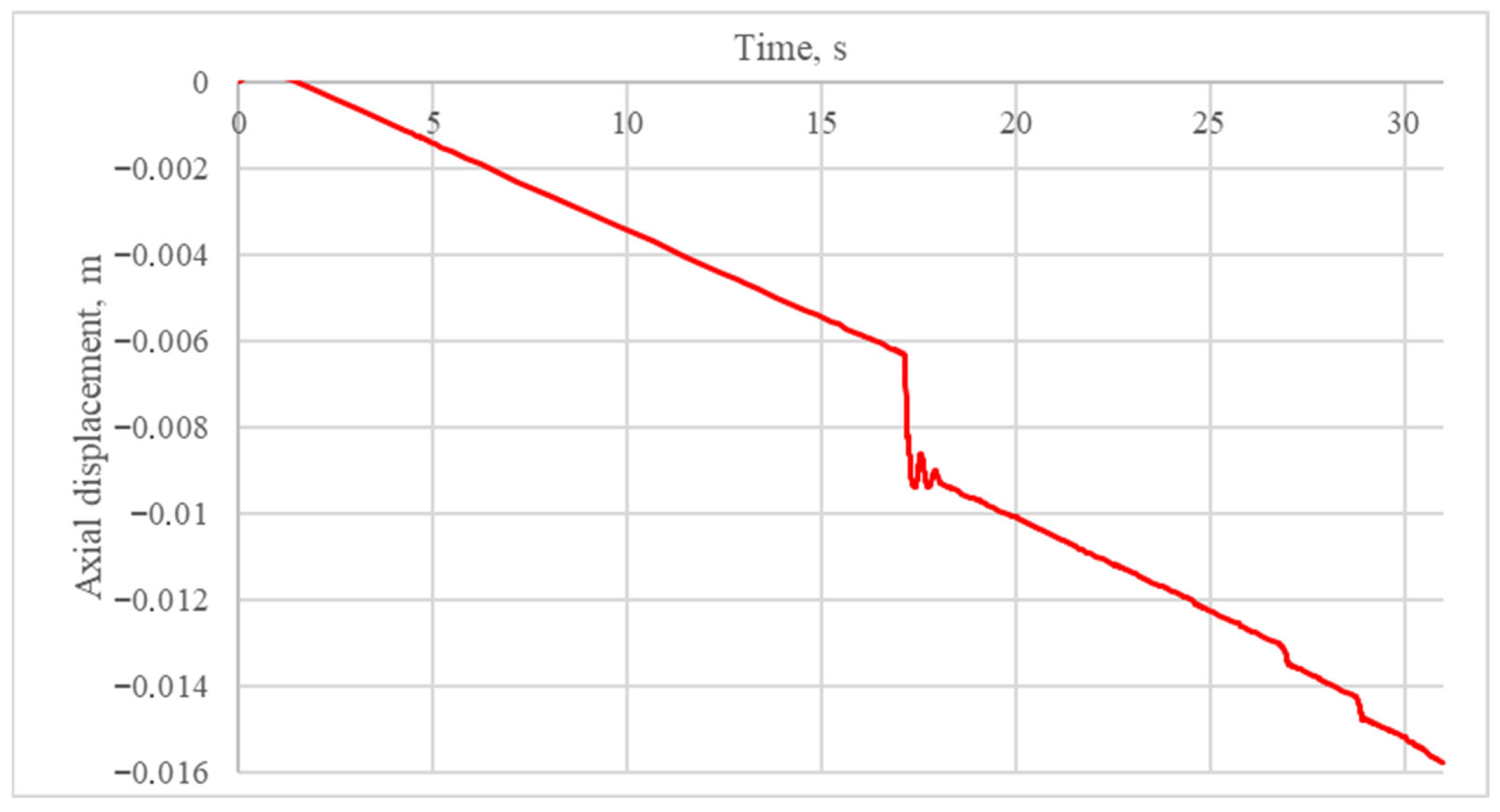
Figure 1. Graph of the dependence of the axial displacement of the pipe’s end on time for a reference experiment without friction.
Eng 06 00306 g001
Figure 2. Drill pipe losing the “straight” stability configuration.
Eng 06 00306 g002
Figure 3. Transitional state.
Eng 06 00306 g003
Figure 4. Helical configuration.
Eng 06 00306 g004
Figure 5. Graph of the dependence of the axial displacement of the drill pipe’s end on time in the reference experiment with friction.
Eng 06 00306 g005
Figure 6. Deflection of the drill pipe under axial loading, gravity, and the presence of tool joints.
Eng 06 00306 g006
Figure 7. Series of experiments with axial vibrations without friction.
Eng 06 00306 g007
Figure 8. Series of experiments with axial vibrations with friction.
Eng 06 00306 g008
Figure 9. Series of experiments with lateral vibrations without friction.
Eng 06 00306 g009
Figure 10. Series of experiments with lateral vibrations with friction.
Eng 06 00306 g010
Figure 11. Series of experiments with vertical vibrations without friction.
Eng 06 00306 g011
Figure 12. Series of experiments with vertical vibrations with friction.
Eng 06 00306 g012
Figure 13. Generalized deformation schemes for a buckled drill string section under axial loading. (a) Scheme with an instantaneous transition into the helical buckling state. (b) Scheme with a transitional section of a sinusoidal buckling. I—section of diagram corresponding to the straight form of stability; II—section of diagram corresponding to sinusoidal buckling; III—section of diagram corresponding to helical buckling.
Eng 06 00306 g013
Figure 14. Comparison of displacement values, calculated and obtained during the reference experiment.
Eng 06 00306 g014
Figure 15. Comparison of displacement values, calculated and obtained during the experiment with vibrations.
Eng 06 00306 g015
Table 1. Parameter λ s t r in the formula of the critical load of helical buckling in the approaches of various researchers.
ResearchersHelical Buckling
Chen, Cheatham [20] 2 2
Kuru, Cunha, Qu, Martinez Miska, Volk [21] 4 2
Wu, Juvkam-Wold [22] 2 ( 2 2 1 )
Table 2. Parameter λ s t r in the critical load formula for an unstable sinusoidal configuration.
ResearchersUnstable Sinusoidal/Helical Buckling
Cunha (1995) [14] 2 2
Kuru, Cunha, Qu, Martinez, Miska, Volk (1996) [21]3.75
Table 3. Correlation of typical frequencies with types of vibrations.
Type of VibrationFrequency, Hz
Self-excited vibrations of the drill string caused by contact of tool joints with the borehole wall, hook load fluctuations due to drawworks brake operation, vibrations in the turbodrill thrust bearing due to drilling fluid pulsations≈1
Bit bounce, including waviness of a well bottom1–40
Bit BHA forward whirl<5
Bit backward whirl<50
BHA backward whirl<20
BHA harmonic resonance<5
Parametric resonance<10
Disclaimer/Publisher’s Note: The statements, opinions and data contained in all publications are solely those of the individual author(s) and contributor(s) and not of MDPI and/or the editor(s). MDPI and/or the editor(s) disclaim responsibility for any injury to people or property resulting from any ideas, methods, instructions or products referred to in the content.