Article

Experimental Study on Failure Characteristics and Energy Evolution Law of Coal–Rock Combination Body Under Different Quasi-Static Loading Rates

1
College of Energy and Mining Engineering, Shandong University of Science and Technology, Qingdao 266590, China
2
State Key Laboratory of Coal Resources and Safe Mining, School of Mines, China University of Mining and Technology, Xuzhou 221116, China
*
Author to whom correspondence should be addressed.
Eng 2025, 6(11), 287; https://doi.org/10.3390/eng6110287
Submission received: 18 September 2025 / Revised: 21 October 2025 / Accepted: 23 October 2025 / Published: 27 October 2025
(This article belongs to the Section Chemical, Civil and Environmental Engineering)

Abstract

The advancing speed of the coal mining face has a significant impact on the mining-induced stress and energy accumulation of the surrounding rock. To explain the influence mechanism from a mesoscopic perspective, this study conducted a uniaxial compression test on the coal–rock combination body under different quasi-static loading rates, and analyzed their mechanical properties, failure characteristics, acoustic emission characteristics and energy evolution characteristics. The main findings are as follows: The uniaxial compressive strength and elastic modulus of the coal–rock combination body show a variation law of first increasing and then decreasing with the increase in loading rate, while the degree of impact failure significantly increases gradually as the loading rate rises. With the increase in loading rate, there is a tendency that the AE parameters concentrate from the first two stages to the latter two stages. The post-peak residual elastic energy density of the coal–rock combination body increases gradually with the increase in loading rate. The formation of the advancing speed effect of mining-induced stress concentration and elastic energy accumulation in coal–rock masses is caused by the “competitive” interaction between fracture propagation and coal matrix damage when the coal component in the coal–rock combination is deformed under stress.

1. Introduction

As the mining depth of coal resources continues to increase, the dynamic disasters faced in deep mining have become increasingly prominent. Among these, rock burst, as one of the typical mine dynamic disasters, has become a key bottleneck restricting the safe and efficient mining of deep coal resources. Relevant research conclusions indicate that the advancing speed of the working face has a significant impact on the failure mode of the coal mass: the higher the advancing speed, the more likely the coal mass is to undergo impact failure [1,2,3]. Furthermore, some scholars, in combination with specific working faces, have attempted to establish the relationship between the advancing speed of the working face and the loading rate of the coal mass [4] and then used rock mechanics testing methods to analyze the influence law of the advancing speed on the failure mode of the coal mass. As a type of porous geological material, the mechanical properties of coal mass exhibit an obvious loading rate effect, which has been confirmed by numerous previous research results.
For example, Wu et al. [5] concluded that the damage degree of coal samples increases significantly with the increase in loading rate under the action of compressive-shear load. Feng et al. [6] obtained that the evolution law of deformation and permeability parameters of raw coal is basically consistent with the change in loading rate. Zhang et al. [7,8,9,10] studied the acoustic emission characteristics of coal samples under different strain rates, constructed a damage model based on acoustic emission characteristic parameters and analyzed the damage law of coal samples. Liu et al. [11,12] concluded that within the range of quasi-static loading rates, as the loading rate increases, the failure mode of coal samples transitions from tension-shear failure to ejection failure. Using the charge induction and microseismic synchronous comprehensive monitoring system, Liu et al. [13] studied the characteristics of charge induction and microseismic signals during the deformation and fracture process of coal and rock under different loading rates. Li et al. [14] studied and revealed the loading rate effect of the mechanical properties of coal, providing a reference basis for controlling the stability of residual coal pillars. Zhou et al. [15,16] concluded that the compressive strength of coal with bursting liability increases as the loading rate increases. Xue et al. [17] concluded that when the loading rate is relatively high, the internal microcracks of coal samples have no time to develop and propagate, and the failure of coal samples is sudden. Jing et al. [18] employed uniaxial compression tests and the digital image correlation method to analyze the crack propagation characteristics of coal samples under different loading rates and reveal the intrinsic correlation between crack propagation characteristics and loading rates. Khan et al. [19] analyzed the infrared radiation characteristics of coal samples under different loading rates and established a method for identifying early precursors of coal failure. In addition, other scholars have also considered the influences of other factors (such as water [20,21] and gas [22,23,24]) together with loading rate on the mechanical properties and failure modes of coal samples. From a mesoscopic perspective, the failure of coal mass is the final result of the generation, propagation, and connection of internal defects, pores, and fractures driven by energy [25,26,27]. Under deep mining conditions, affected by high in situ stress, the stress interaction between the coal seam and the roof rock stratum is strong. The damage evolution and failure characteristics of the coal mass at the working face depend not only on its own physical and mechanical properties but also on the combined structure between the coal seam and the rock stratum [28,29].
Among the current research results, the loading rates used in tests on the loading rate effect of the coal–rock combination body fall outside the scope of quasi-static mechanics. However, during coal seam mining, the advancing process of the working face is basically a stable process, and most of it belongs to the scope of quasi-static mechanics. Within the range of quasi-static loading rates, in-depth research on the failure modes and energy evolution laws of coal-rock combinations under different loading rate conditions is still insufficient. Therefore, this study took the coal–rock combination body as the research object, conducted uniaxial compression tests on the coal–rock combination body under different quasi-static loading rates, analyzed its strength, deformation and failure characteristics, the variation law of acoustic emission characteristic parameters, as well as the accumulation, dissipation, and release processes of strain energy, and revealed the formation mechanism of the advancing speed effect on the mining-induced stress concentration and elastic energy accumulation of coal–rock mass. In this paper, we introduce three hypotheses: (1) The ratio of uniaxial compressive strength to elastic modulus varies nonlinearly with the loading rate. (2) The concentration interval of acoustic emission parameters shifts toward the later stage of the stress–strain curve. (3) The elastic strain energy in the post-peak stage increases with the enhancement of the impact property of specimen failure.

2. Materials and Methods

2.1. Sample Preparation

The test coal samples were obtained from large coal blocks in the 23,908 working face of the No. 9 coal seam at Zhangshuanglou Coal Mine, Xuzhou City, China. These were processed through drilling and cutting into Φ50 mm × 50 mm coal samples. Rock samples were obtained from the fine sandstone of the immediate roof of the working face. These were also processed through drilling and cutting into Φ50 mm × 50 mm rock samples. Coal and rock samples were bonded together using marble adhesive to form composite specimens measuring Φ50 mm × 100 mm, as shown in Figure 1.
Through testing, the coal sample has well-developed internal fractures, with an ash content of 17.9%, a moisture content of 1.8%, and a uniaxial compressive strength of approximately 16 MPa, showing a weak rock burst tendency. The rock sample is relatively dense, with well-developed bedding, a uniaxial compressive strength of about 50 MPa, and exhibits strong rock burst tendency. The physical properties of the coal–rock combination body are shown in Table 1. It can be observed that the average density of specimens is approximately 1886 kg/m3. The minimal difference in density indicates comparable levels of compaction and pore development, thereby the experimental deviations caused by variations in material homogeneity can be reduced.

2.2. Experimental Equipment

The test was conducted on an MTS C64.106 electro-hydraulic servo universal testing machine (Figure 2), equipped with an Express-8 acoustic emission monitoring system to capture fracture information during the loading process of the coal–rock composite. The acoustic emission threshold was set at 40 dB, with peak detection time PDT = 50 μs, hammer detection time HDT = 200 μs, and hammer lockout time HLT = 300 μs. The signal acquisition frequency was 200 kHz. A total of 6 acoustic emission probes are arranged, with 2 placed on the upper side, and 4 on the lower side, as shown in Figure 2.

2.3. Test Scheme

In rock mechanics testing, strain rate (dσ/dε) is typically used to classify different loading rates, where dσ/dε < 10−6/s falls within the static range, 10−6/s < dσ/dε < 10−4/s corresponds to the quasi-static range, and dσ/dε > 10−4/s belongs to the dynamic range. During coal seam mining, the face advance is essentially a stable process, predominantly falling within the quasi-static category [30]. The displacement loading rate is designed at four levels: 0.01 mm/min, 0.03 mm/min, 0.11 mm/min, and 0.16 mm/min. Given the specimen height of 100 mm, the corresponding strain rates for each loading rate are 1.7 × 10⁻⁶/s, 5.0 × 10⁻⁶/s, 1.8 × 10⁻⁵/s, and 2.7 × 10⁻⁵/s, respectively, meeting the requirements for the quasi-static category. The main experimental procedure is shown in Figure 3.

3. Results

3.1. Strength, Deformation, and Failure Characteristics

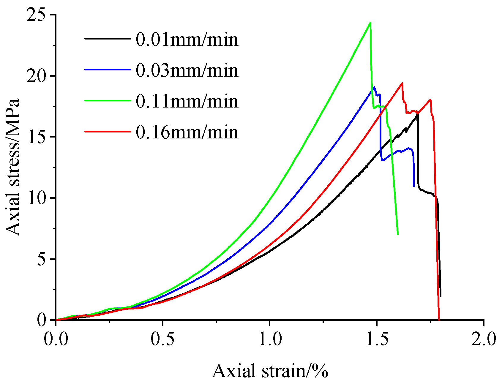
Figure 4 illustrates the evolution of stress versus strain in coal–rock assemblies under different loading rates. It is evident that the coal–rock assemblies primarily undergo a consolidation stage, an elastic deformation stage, and a post-peak failure stage. During the consolidation stage, compaction and closure of primary microcracks, pores, and coal-rock interfaces within the composite cause axial stress to increase slowly, resulting in a concave stress–strain curve. In the elastic deformation stage, the axial stress growth rate significantly increases compared to the consolidation stage, exhibiting near-linear growth with increasing strain. During the post-peak failure stage, axial stress exhibits two distinct rapid drops. The first obvious stress drop is caused by the penetration of macroscopic fractures in the coal sample, while the second obvious stress drop results from the complete bearing failure of the coal–rock composite. The difference lies in the loading rate: at 0.01 mm/min, axial stress first decreases slowly after the first stress drop and then rapidly; whereas at loading rates of 0.03–0.16 mm/min, axial stress first increases after the first stress drop and then rapidly decreases.
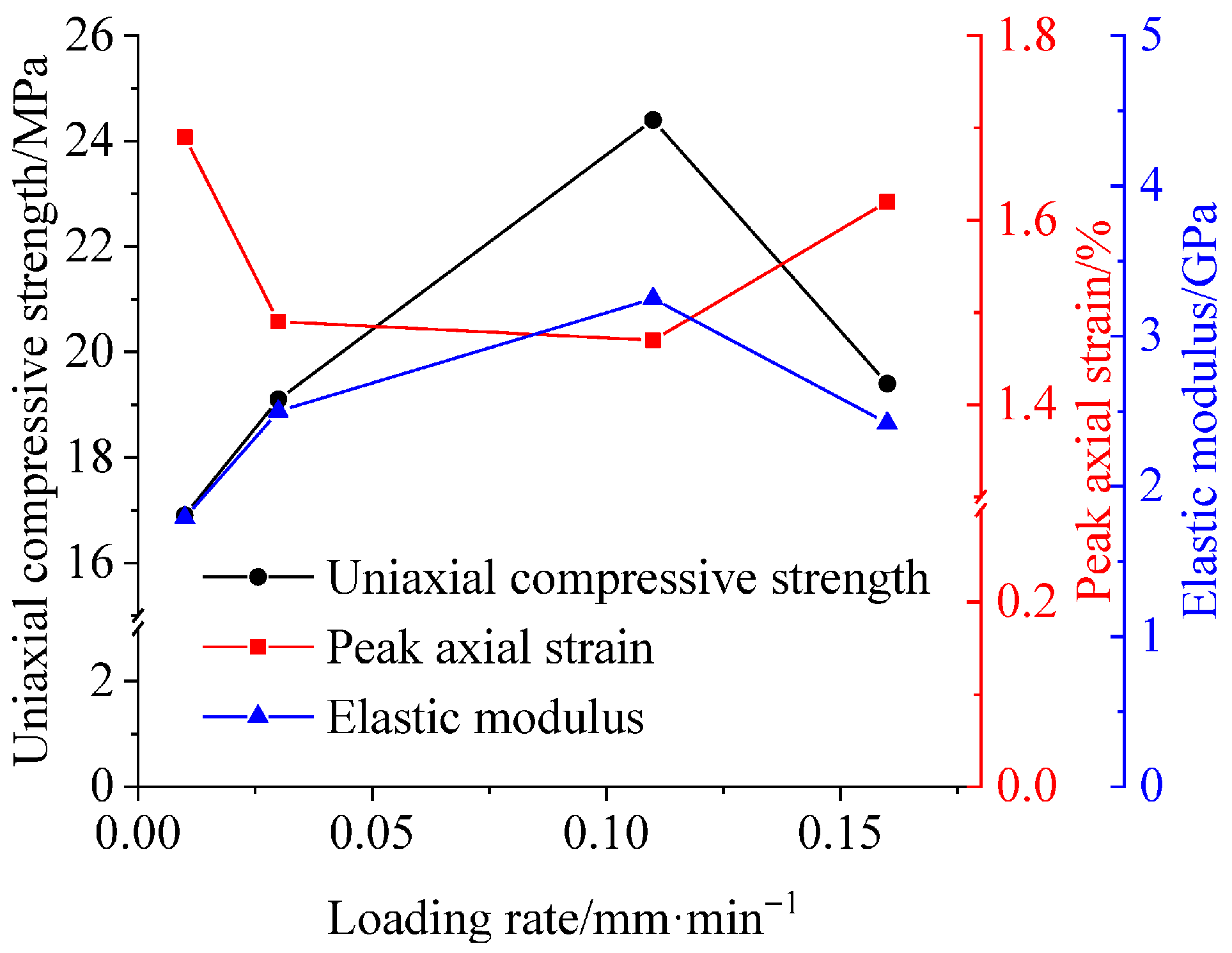
To compare the uniaxial compressive strength, peak axial strain, and elastic modulus of coal–rock composites under different loading rates, corresponding strength and deformation parameters were obtained from the stress–strain relationship for each loading rate condition, as shown in Figure 5. It can be observed that within the quasi-static loading rate range, the uniaxial compressive strength of the coal–rock composite exhibits an initial increase followed by a decrease as the loading rate increases. The elastic modulus follows a similar pattern, while the peak axial strain shows an initial decrease followed by an increase.
Uniaxial compressive strength and elastic modulus reach their minimum values at a loading rate of 0.01 mm/min (16.9 MPa and 1.79 GPa, respectively) and their maximum values at 0.11 mm/min (24.4 MPa and 3.25 GPa, respectively). Correspondingly, the peak axial strain reached its maximum value of 1.69% at a loading rate of 0.01 mm/min and its minimum value of 1.47% at 0.11 mm/min.
The final failure morphology of the coal–sand composite is shown in Figure 6. Observation of the final failure morphology reveals that the coal component is the primary source of failure, while the sandstone component exhibits virtually no visible surface damage. At a loading rate of 0.01 mm/min, failure of the coal component primarily manifested as localized axial splitting. After reaching peak load, the specimen remained stable without significant audible failure sounds. Coal particles slowly exfoliated from the main body in a flaky manner, with minimal impact failure effects. At a loading rate of 0.03 mm/min, both splitting and shear failure coexisted in the coal component, with splitting being predominant. After reaching peak load, the specimen gradually destabilized with faint failure sounds, and coal fragments detached relatively quickly from the main body, though impact failure effects remained insignificant. At a loading rate of 0.11 mm/min, the coal component primarily exhibited shear failure. Following the formation of the first significant stress drop, the specimen rapidly destabilized with a distinct failure sound. The coal body ejected from the main body in the form of debris or fragments, and impact failure effects began to manifest. At a loading rate of 0.16 mm/min, the coal component primarily exhibited shear failure. Upon reaching peak load, the specimen rapidly destabilized with a loud fracture sound, and coal fragments were ejected from the main body at high speed, demonstrating a pronounced impact failure effect.

3.2. Damage Evolution Characteristics

From the loaded deformation to unstable failure of coal–rock masses, internal cracks continuously initiate, propagate, and converge. This process generates acoustic emission (AE) signals, which can be captured by AE monitoring equipment. Analyzing the variation patterns of AE characteristic parameters helps to further understand the evolution characteristics of internal damage in coal–rock combination body. The commonly used AE signal analysis methods mainly fall into two categories: parameter analysis method and waveform analysis method [31]. Among them, the parameter analysis method can be further subdivided into basic parameter analysis method and characteristic parameter analysis method: The basic parameter analysis method mainly focuses on AE basic parameters such as ring count, energy, and amplitude. The characteristic parameter analysis method mainly targets secondary structural parameters, such as b-value, RA value (Rise Time/Amplitude), and average frequency (AF). This study primarily adopts the basic parameter analysis method to investigate the damage evolution process and fracture mode of coal–rock combination specimens under different loading rates.
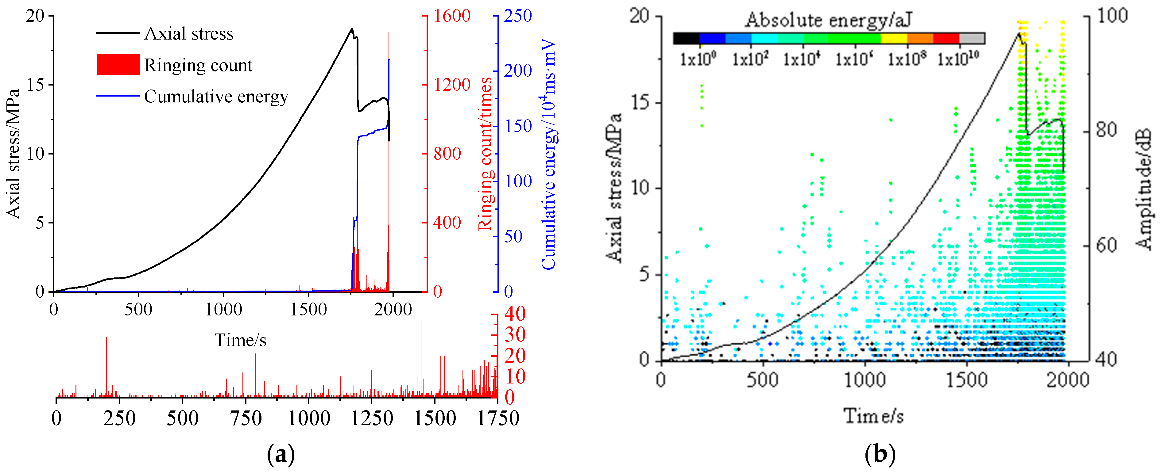
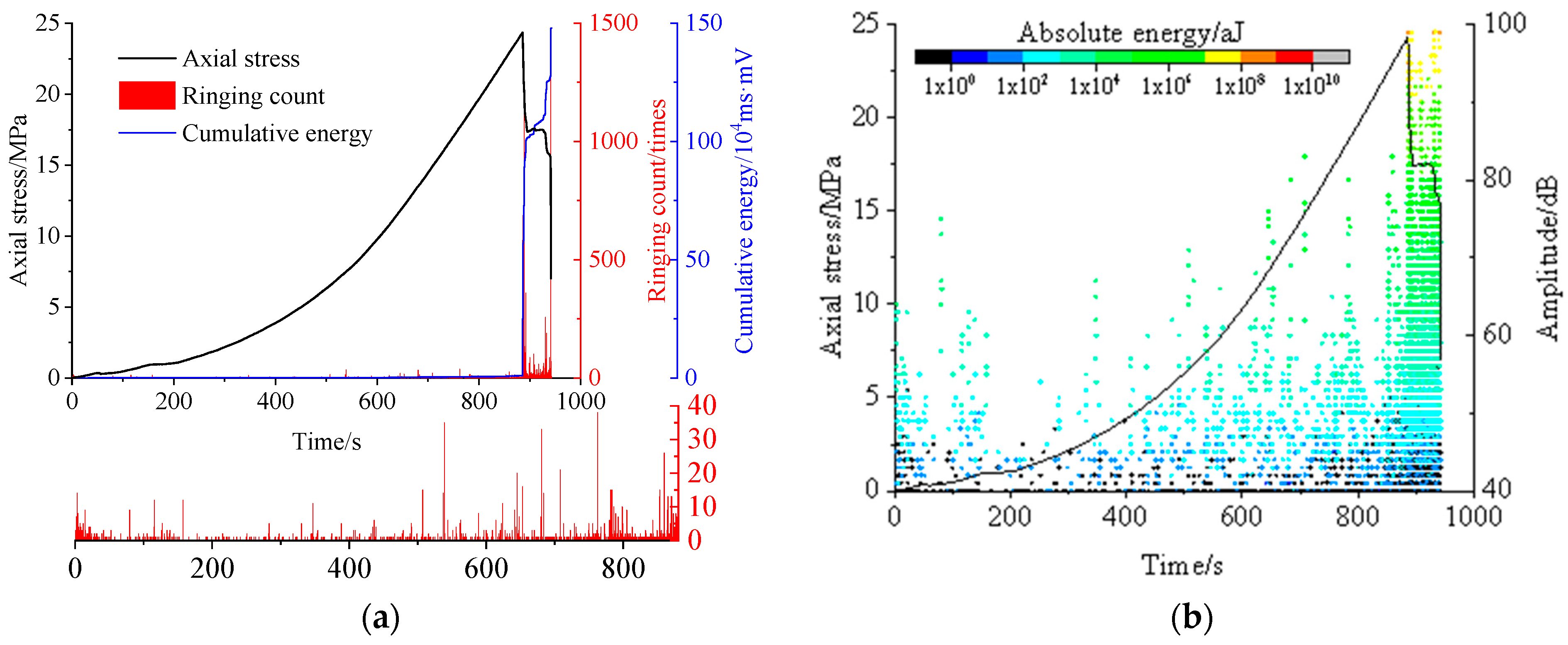
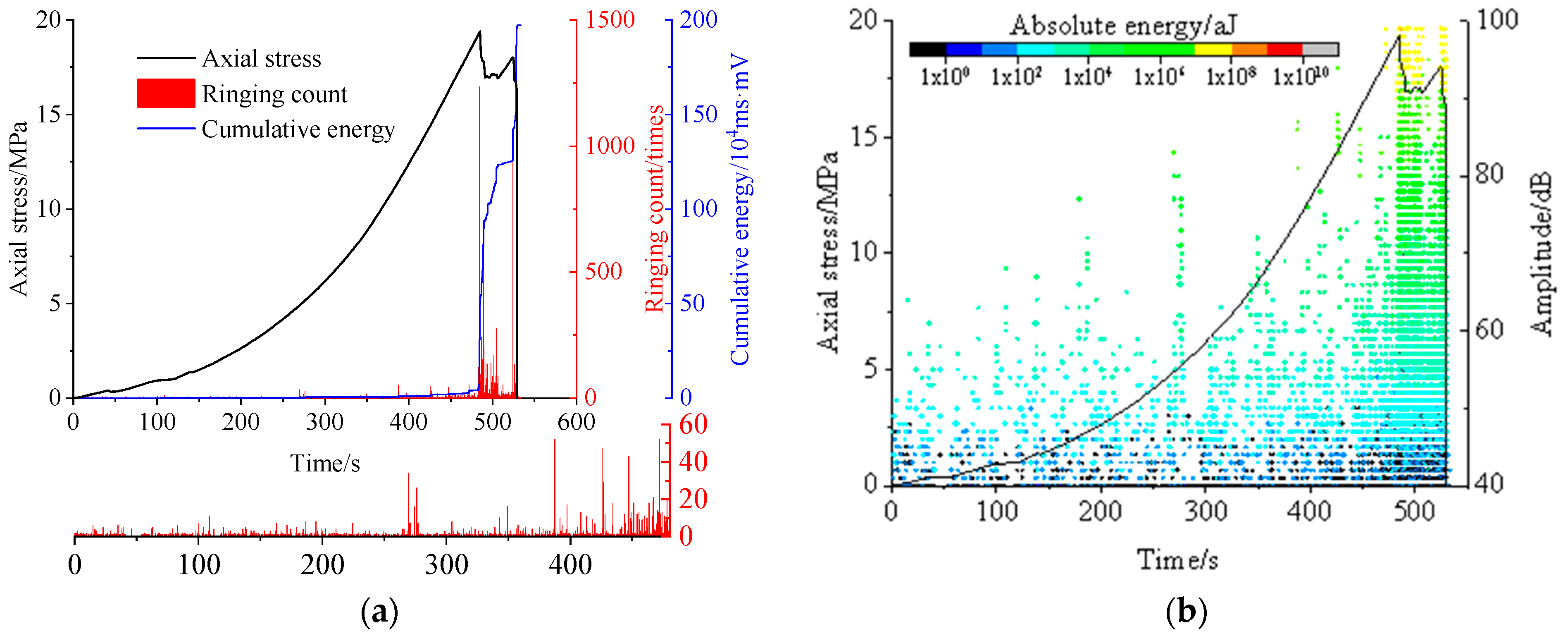
As shown in Figure 7, Figure 8, Figure 9 and Figure 10, they respectively present the variations in acoustic emission (AE) ring count, cumulative energy, amplitude, and absolute energy with time during the deformation and failure process of the coal–rock combination body under loading rates of 0.01 mm/min, 0.03 mm/min, 0.11 mm/min, and 0.16 mm/min. According to the variation trend in the stress–strain curve and combined with the evolution process of AE ring count over time, the entire loading-induced failure process of the coal–rock combination body can be divided into four stages, which are successively Stage I (crack compaction stage), Stage II (stable crack propagation stage), Stage III (unstable crack propagation stage), and Stage IV (crack penetration and failure stage).
As can be seen from Figure 7, when the loading rate is 0.01 mm/min:
During the loading process from 0 to 3000 s, the coal–rock combination specimen is in the crack compaction stage. The axial stress increases relatively slowly; under the action of the load, the original microcracks and pores inside the specimen are gradually compacted. The acoustic emission (AE) ring count is small, with a maximum value of no more than 20 counts. Meanwhile, the AE cumulative energy shows almost no increase, the amplitude of AE events ranges from 0 to 80 dB, and the absolute energy of AE events is within the range of 1 to 106 aJ.
During the loading process from 3000 to 8000 s, the specimen enters the stable crack propagation stage. The axial stress exhibits a growth trend from slow to fast. The original microcracks and pores in the specimen expand, accompanied by the formation of new cracks. During this loading process, the AE ring count increases slightly, with several relatively high values, but the maximum value is still below 40 counts. Due to the small size of micro-fractures and low energy release, the AE cumulative energy still does not increase significantly, and there is no obvious difference in the magnitude of AE amplitude and absolute energy compared with the previous stage.
Approximately during the loading process from 8000 to 9500 s, the specimen is in the unstable crack propagation stage. The axial stress increases approximately linearly with time, during which three obvious stress drops occur, accompanied by the formation of three relatively large AE ring counts (about 380 counts). The primary micropores and fractures in the sandstone component and coal component gradually expand and interconnect, leading to a decrease in the load-bearing capacity of the coal–rock composite. At the same time, the AE cumulative energy shows three obvious rapid increases, reaching a total of 5 × 10⁵ ms·mV. Two observations also indicate that the cracks inside the specimen are expanding and converging rapidly: the AE amplitude reaches above 80 dB, and the absolute energy shows relatively large values ranging from 106 to 109 aJ. These phenomena demonstrate that the specimen is in an unstable state, approaching failure and instability.
During the loading process after 9500 s, the specimen enters the crack penetration and failure stage. The axial stress drops rapidly twice: experimental observation shows that one drop is caused by the penetration of macroscopic cracks, and the other is due to the final failure and instability of the specimen. Both stress drops are accompanied by large AE ring counts, reaching approximately 600 counts and 1100 counts, respectively. The AE cumulative energy increases rapidly twice, eventually reaching about 1.9 × 10⁶ ms·mV. Both the AE amplitude and absolute energy remain at relatively high levels, reaching up to 100 dB and 109 aJ, respectively.
As can be seen from Figure 8, when the loading rate is 0.03 mm/min:
During the loading process from 0 to 250 s, the coal–rock combination specimen is in the crack compaction stage. The axial stress increases slowly, and the generation of acoustic emission (AE) ring counts is mainly due to the compaction and closure of original microcracks and pores. During this process, the AE amplitude is relatively low, basically ranging from 0 to 60 dB, and the AE absolute energy is also low, basically within the range of 1 to 103 aJ. Therefore, the AE cumulative energy shows almost no obvious increase.
During the loading process from 250 to 1400 s, the specimen enters the stable crack propagation stage. In the first 250 s of this stage, the AE ring count is almost zero; after 250 s, AE ring counts begin to occur frequently, indicating that cracks have started to expand and new cracks have begun to form at this point. The AE amplitude generally shows a steady growth trend, but due to the small size of micro-fractures, the AE absolute energy remains low, and the increase in cumulative energy is not significant.
During the loading process from 1400 to 1750 s, the specimen is in the unstable crack propagation stage. It can be observed that although the numerical value of AE ring count does not increase significantly, its frequency is significantly higher than that in the previous two stages. The numerical values of AE amplitude and absolute energy are relatively close to those in the previous two stages, both at low levels, so the increase in cumulative energy is not obvious.
During the loading process after 1750 s, the specimen enters the crack penetration and failure stage. The axial stress drops suddenly twice: observations during the experiment show that the first stress drop corresponds to the generation of macroscopic cracks in the specimen, but the structure does not lose stability and still has a certain load-bearing capacity, so the axial stress increases slightly again. The second stress drop corresponds to structural instability and complete failure of the specimen. Two relatively high ring counts (approximately 600 counts and 1500 counts, respectively) occur when the two stress drops happen. Corresponding to this, the AE amplitude and absolute energy are significantly higher than those in the first three stages, reaching up to 100 dB and 109 aJ, respectively. The cumulative energy increases rapidly in this stage, eventually reaching 2.1 × 10⁶ ms·mV.
As can be seen from Figure 9, when the loading rate is 0.11 mm/min:
During the loading process from 0 to 150 s, the coal–rock combination specimen is in the crack compaction stage. Affected by the compaction and closure of original microcracks and pores, a relatively large number of acoustic emission (AE) ring counts are generated, with a maximum of approximately 15 counts. The AE amplitude ranges from 0 to 70 dB, the absolute energy is relatively low (with a maximum of no more than 104 aJ), and there is no obvious increase in cumulative energy.
During the loading process from 150 to 520 s, the specimen enters the stable crack propagation stage. The maximum AE ring count reaches approximately 35 counts. The numerical values of AE amplitude and absolute energy are close to those in the previous stage, and there is still no significant increase in cumulative energy.
During the loading process from 520 to 850 s, the specimen is in the unstable crack propagation stage. The AE ring count increases significantly compared with the previous stage, and several obvious extreme values appear—this reflects that the expansion and convergence of cracks in this stage are relatively intense. However, due to the small fracture scale, the AE amplitude and absolute energy remain at low levels, so the cumulative energy does not increase significantly.
During the loading process after 850 s, the specimen enters the crack penetration and failure stage. The axial stress drops sharply twice: observations during the experiment show that the first stress drop corresponds to the formation of macroscopic cracks, while the second stress drop corresponds to the instability and failure of the specimen. These two stress drops are accompanied by two groups of large AE ring counts, both reaching approximately 1250 counts. Meanwhile, the AE amplitude and absolute energy also reach their maximum values, which are 100 dB and 1010 aJ, respectively. The cumulative energy increases rapidly accordingly, eventually reaching 1.5 × 10⁶ ms·mV.
As can be seen from Figure 10, when the loading rate is 0.16 mm/min:
During the loading process from 0 to 50 s, the coal–rock combination specimen is in the crack compaction stage. The captured acoustic emission (AE) ring counts are extremely small, with fewer than 10 counts for almost each event. The AE amplitude is also at a low level, basically less than 60 dB, and the absolute energy is generally in the range of 1 to 103 aJ. There is almost no increase in AE cumulative energy.
During the loading process from 50 to 300 s, the specimen enters the stable crack propagation stage. The ring counts of the captured AE events start to increase, with an average of approximately 10 counts. The AE amplitude also rises in this stage, reaching a maximum of 80 dB, and the absolute energy begins to exceed 104 aJ. However, due to the small number of high-energy events, there is no significant increase in AE cumulative energy.
During the loading process from 300 to 480 s, the specimen is in the unstable crack propagation stage. The ring counts of most AE events are more than 10, and the ring count of individual AE events can reach approximately 50. In this stage, the AE amplitude shows a transition from low to high, with a maximum of around 90 dB. Affected by this, the AE cumulative energy starts to increase.
During the loading process after 480 s, the specimen enters the crack penetration and failure stage. In this process, the ring counts of AE events are generally more than 100. The axial stress drops sharply twice, accompanied by two high ring counts (reaching approximately 1250 counts and 1000 counts, respectively). Observations during the experiment show that the first stress drop is caused by the formation of macroscopic cracks in the specimen, and the second stress drop is due to the failure and instability of the specimen. The AE amplitude is generally at a high level; the elastic strain energy accumulated in the specimen before the peak is released violently in this stage, with the absolute energy reaching above 108 aJ. The AE cumulative energy rises rapidly, eventually reaching 2 × 10⁶ ms·mV.
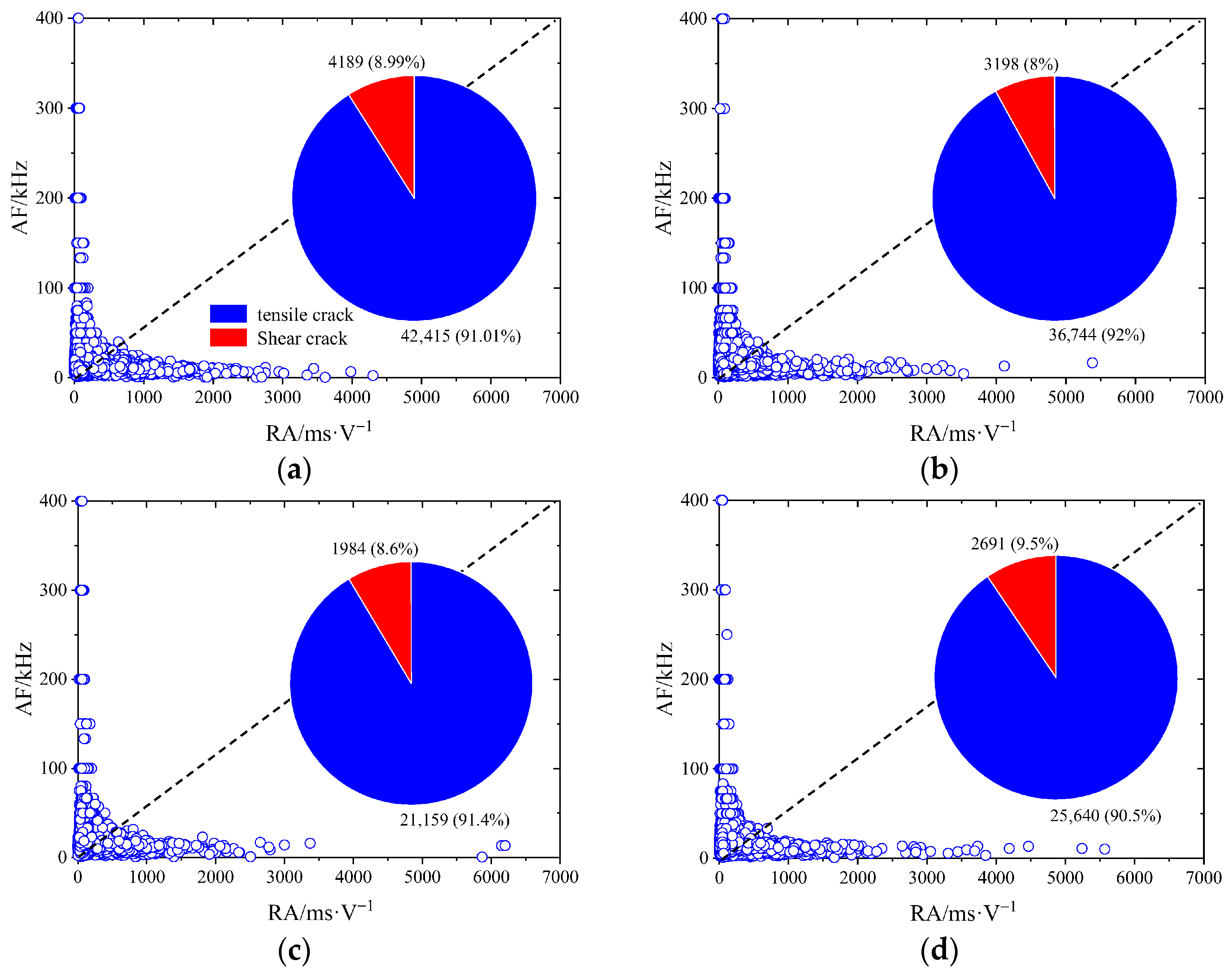
The data distribution of RA and AF values during the deformation and failure process of coal–rock combinations under different loading rates is shown in Figure 11. It can be seen that the failure mode of coal-rock combinations is dominated by tensile failure. When the loading rate is 0.01 mm/min, the proportions of tensile cracks and shear cracks are 91.01% and 8.99%, respectively; when the loading rate is 0.03 mm/min, the proportions are 92% and 8%, respectively; when the loading rate is 0.11 mm/min, the proportions are 91.4% and 8.6%, respectively; and when the loading rate is 0.16 mm/min, the proportions are 90.5% and 9.5%, respectively. The loading rate has little effect on the failure type of coal–rock combinations. In terms of the number of failure events, when the loading rate is 0.01 mm/min, the number of tensile failures is 42,415, the number of shear failures is 4189, and the total number is 46,604; when the loading rate is 0.03 mm/min, the number of tensile failures is 36,744, the number of shear failures is 3189, and the total number is 39,942; when the loading rate is 0.11 mm/min, the number of tensile failures is 21,159, the number of shear failures is 1984, and the total number is 23,143; when the loading rate is 0.16 mm/min, the number of tensile failures is 25,640, the number of shear failures is 2692, and the total number is 28,332.
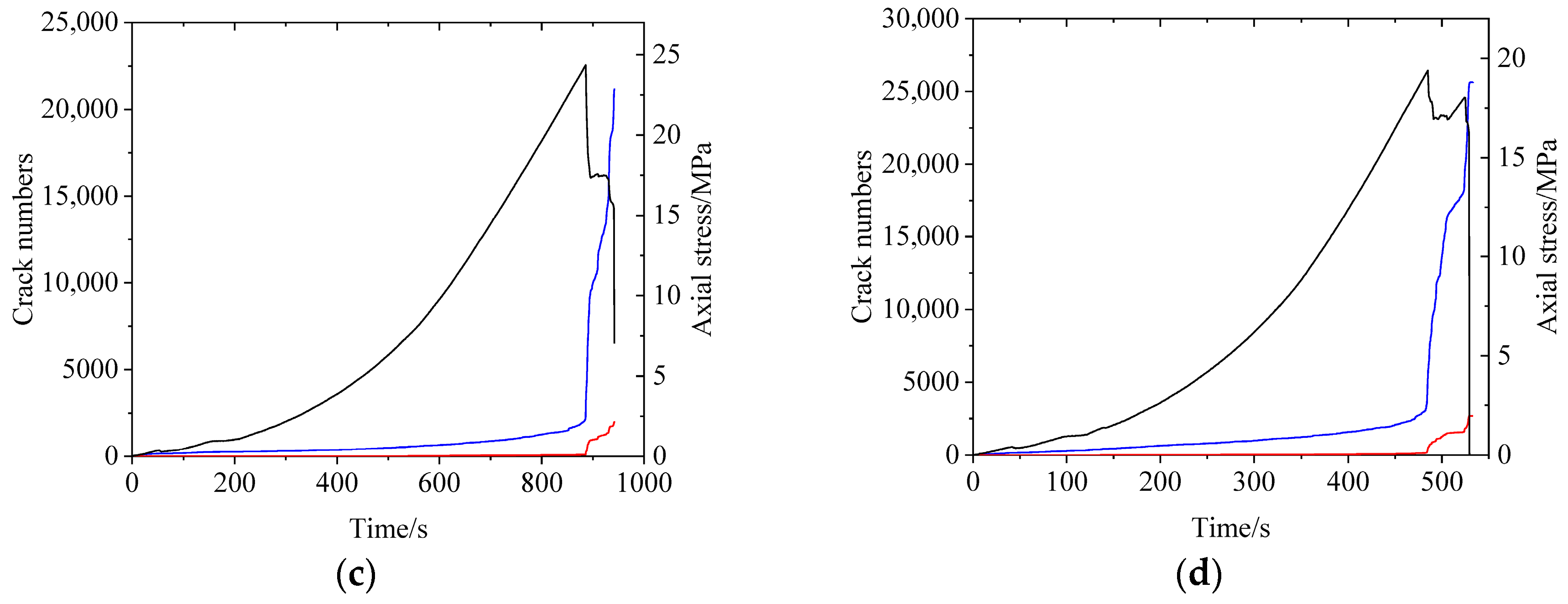
In the previous text, from an overall perspective, the distribution characteristics of different types of failure events after the final failure of the coal–rock combination were analyzed. To further compare and analyze the evolution process of tensile fractures and shear fractures in the coal–rock combination over time under different loading rate conditions, the growth curves of the number of tensile fractures and shear fractures over time under each loading rate condition were obtained through data statistics, as shown in Figure 12.
It can be seen that before the coal–rock combination reaches the peak load, tensile failure mainly occurs inside it, with the cumulative number of tensile fracture events increasing slowly and the cumulative number of shear fracture events showing no significant growth. After reaching the peak load, the specimen undergoes mixed tension–shear failure, dominated by tensile failure, where the cumulative number of tensile fracture events increases rapidly and the cumulative number of shear fracture events increases slightly. To quantitatively analyze the damage evolution process of coal–rock combinations under different loading rate conditions, the damage degree of coal–rock combinations is defined here as the ratio of the cumulative number of fracture events at different loading progress to the total number of fracture events when the specimen is completely damaged:
D = X σ i X σ F
where Xσi is the cumulative number of fracture events when loaded to a certain stress level; XσF is the total number of fracture events when the specimen is completely damaged.
When the loading rate is 0.01 mm/min, the number of tensile fracture events at the peak load reaches 20,197, and the maximum number of shear fracture events reaches 1878; thus, Xσi is 22,075, and the damage degree D at this time is 47.4%. When the loading rate is 0.03 mm/min, the number of tensile fracture events at the peak load reaches 3582, and the maximum number of shear fracture events reaches 331; accordingly, Xσi is 3913, with the damage degree D being 20.3%. At a loading rate of 0.11 mm/min, the number of tensile fracture events at the peak load is 2674, and the maximum number of shear fracture events is 145, resulting in an Xσi of 2819 and a damage degree D of 12.2%. When the loading rate is 0.16 mm/min, the number of tensile fracture events at the peak load reaches 5328, and the maximum number of shear fracture events reaches 423, making Xσi 5751 and the damage degree D 9.8%. It can be seen that the damage degree of the coal–rock combination at the peak load decreases with the increase in the loading rate.

3.3. Energy Evolution Characteristics

During the test, let the total input energy generated by the work performed by the loading system on the coal–rock combination body be U. Assuming there is no heat exchange between the coal–rock combination body and the surrounding environment, it can be derived according to the first law of thermodynamics that
U = U 1 + U 2 ,
where U1 is the releasable elastic strain energy, which is mainly generated by the elastic deformation of the coal–rock combination body; U2 is the dissipated energy, which is mainly used for the formation of internal damage and plastic deformation of the coal–rock combination body [32].
The total input energy U can be obtained through the integral calculation of the stress–strain curve [32]:
U = σ 1 d ε 1 + σ 2 d ε 2 + σ 3 d ε 3 ,
The calculation method of the releasable elastic strain energy is as follows [32]:
U 1 = 1 2 E 0 [ σ 1 2 + σ 2 2 + σ 3 2 2 ν ( σ 1 σ 2 + σ 2 σ 3 + σ 1 σ 3 ) ] ,
where E0 is the elastic modulus of the coal–rock mass, ν is the Poisson’s ratio of the coal–rock combination body.
Under uniaxial loading conditions, since σ2 and σ3 are zero, the total input energy density, releasable elastic strain energy density, and dissipated energy density can be expressed as follows, respectively:
U = σ 1 d ε 1 U 1 = σ 1 2 2 E 0 U 2 = U U 1 ,
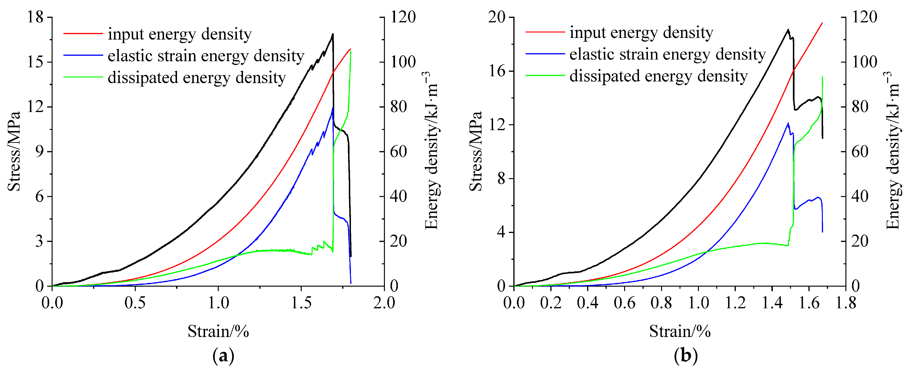
According to Formula (5), during the uniaxial loading process, the evolution processes of the input energy density, elastic energy density, and dissipated energy density of the coal–rock combination body under different loading rates, as functions of axial strain, are shown in Figure 13. It is easy to observe that under different loading rates, the input energy density applied by the test system to the coal–rock combination body exhibits a variation trend of first increasing slowly and then rising rapidly with axial strain. Specifically, when the loading rate is 0.01 mm/min, the maximum input energy density is 105.9 kJ·m−3; when the loading rate is 0.03 mm/min, the maximum input energy density is 117.6 kJ·m−3; when the loading rate is 0.11 mm/min, the maximum input energy density is 130.6 kJ·m−3; when the loading rate is 0.16 mm/min, the maximum input energy density is 123.3 kJ·m−3.
According to the growth patterns of elastic energy density and dissipated energy density in Figure 13, the energy evolution process of the coal–rock combination body during the loaded deformation can be divided into two stages: the pre-peak elastic energy accumulation stage and the post-peak elastic energy release stage. Among them, the pre-peak elastic energy accumulation stage can be further subdivided into three sub-stages: the elastic energy non-accumulation sub-stage, the elastic energy slow accumulation sub-stage, and the elastic energy rapid accumulation sub-stage.
Taking the loading rate of 0.01 mm/min as an example, when the axial strain is in the range of 0–0.5%, the coal–rock combination body is in the elastic energy non-accumulation sub-stage, which corresponds to the previously mentioned crack compaction stage. During this sub-stage, most of the energy input by the testing machine into the specimen is consumed in the compaction of microcracks and pores, resulting in minimal elastic energy accumulation. As can be seen from the figure, the dissipated energy density increases slightly while the elastic energy density shows almost no growth. When the axial strain is in the range of 0.5–1.1%, the coal–rock combination body enters the elastic energy slow accumulation sub-stage, corresponding to the previously discussed stable crack propagation stage. The elastic deformation characteristics of the specimen gradually become prominent, and the coal–rock combination body begins to store elastic energy slowly. Meanwhile, the expansion of existing cracks and the formation of new cracks lead to a slight increase in dissipated energy. Energy dissipation dominates this sub-stage. When the axial strain is in the range of 1.1–1.7%, the coal–rock combination body is in the elastic energy rapid accumulation sub-stage, which corresponds to the aforementioned unstable crack propagation stage. The specimen is in a linear elastic state, and the coal–rock combination body stores a large amount of elastic energy. Energy accumulation is the main feature of this sub-stage. When the axial strain exceeds 1.7%, the coal–rock combination body enters the elastic energy release stage, corresponding to the previously described crack penetration and failure stage. During this stage, the dissipated energy density rises rapidly, indicating that most of the energy input by the testing machine is consumed in the penetration of macroscopic cracks and the friction of fracture surfaces. However, the post-peak elastic energy density remains greater than zero; this part of the energy is converted into the kinetic energy of the broken coal–rock blocks as the specimen fails, driving the broken blocks to burst out from the main body of the specimen, which macroscopically manifests as an impact failure phenomenon.
By comparing Figure 13a–d, it can be observed that the evolution processes of pre-peak elastic energy density and dissipated energy density of the coal–rock combination body are relatively similar under different loading rates, while the evolution processes of post-peak elastic energy density and dissipated energy density exhibit significant differences, which is the main reason for the distinct differences in the final failure modes of the specimens. Under different loading rates, the post-peak elastic energy density undergoes two rapid drops, which coincide with the decrease process of axial stress: The first drop in elastic energy density is caused by the rapid penetration of macroscopic cracks, which leads to the massive dissipation of elastic energy stored in the specimen, and thus the dissipated energy density rises rapidly. The second drop in elastic energy density is due to the overall unstable failure of the specimen, which results in the complete dissipation of the residual elastic energy in the specimen, and accordingly, the dissipated energy density rises rapidly for the second time. Here, the residual elastic energy after the first dissipation is the fundamental source of the kinetic energy that drives the broken coal blocks to separate from the main body of the specimen.
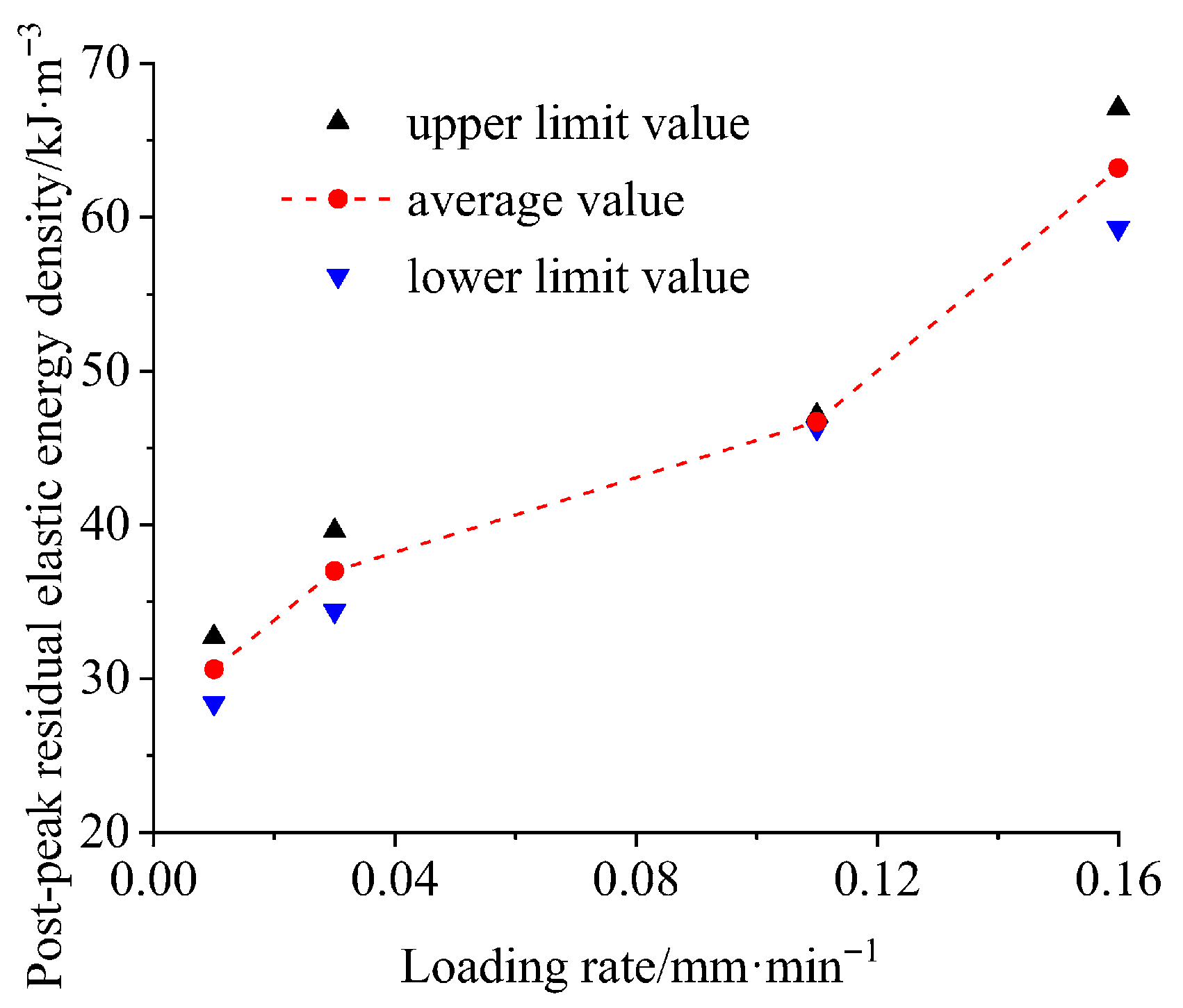
The post-peak residual elastic energy density of the coal–rock combination body under different loading rates is shown in Figure 14. It can be seen that when the loading rate is 0.01 mm/min, the residual elastic energy density ranges from 28.4 to 32.7 kJ/m3, with an average value of approximately 30.6 kJ/m3; when the loading rate is 0.03 mm/min, the residual elastic energy density ranges from 34.4 to 39.6 kJ/m3, with an average value of approximately 37.0 kJ/m3; when the loading rate is 0.11 mm/min, the residual elastic energy density ranges from 46.3 to 47.1 kJ/m3, with an average value of approximately 46.7 kJ/m3; when the loading rate is 0.16 mm/min, the residual elastic energy density ranges from 59.3 to 67.1 kJ/m3, with an average value of approximately 63.2 kJ/m3. The post-peak residual elastic energy density of the coal–rock combination body gradually increases as the loading rate increases.
According to the failure modes of the coal–rock combination body under different loading rates in Section 3.1, the higher the loading rate, the more significant the impact failure effect of the coal–rock combination body. Specifically: When the loading rates are 0.01 mm/min and 0.03 mm/min, the impact failure effect of the coal–rock combination body is not obvious; when the loading rate is 0.11 mm/min, the impact failure effect of the coal–rock combination body is relatively obvious; when the loading rate is 0.16 mm/min, the impact failure effect of the coal–rock combination body is extremely obvious. This indicates that there is a positive correlation between the post-peak residual elastic energy density of the coal–rock combination body and its impact failure effect.

4. Discussion

From the test results in Section 3.3, it can be observed that under different displacement loading rates, there are significant differences in the deformation characteristics, strength characteristics, pre-peak damage degree, and post-peak residual elastic energy density of the coal–rock combination body, as detailed in Table 2. It can be seen that as the loading rate increases, the compressive strength and elastic modulus of the coal–rock combination body first increase and then decrease, reaching their maximum values at a loading rate of 0.11 mm/min. The pre-peak damage degree first decreases and then increases, reaching its minimum value at a loading rate of 0.03 mm/min. The post-peak residual elastic energy density gradually increases with the increase in loading rate, showing a positive correlation with its impact failure effect.
Taking the coal–rock combinations made from on-site collected coal samples and rock samples as the research object, this paper explores their mechanical behaviors under different quasi-static loading rates. For different loading rates, this paper analyzes and compares the evolution laws of mechanical parameters, failure modes, and energy accumulation and release processes of the coal–rock combinations. Similar studies have been conducted separately in previous research. The relationship between rock mechanical behaviors and loading rates is one of the most important research directions in the field of laboratory rock mechanics. In terms of rock strength, some scholars have proposed that there is a positive correlation between rock strength and loading rate [33]. However, it should be noted that the research objects of these studies are mostly high-strength rocks, while the coal–rock combinations used in this paper are of low-strength type. In the study of strength characteristics, the test results show that the uniaxial strength of coal–rock combinations presents a trend of “first increasing and then decreasing” with the change in loading rate, and there is a threshold range of loading rate during this process. This result is highly consistent with the research conclusions of Li et al. [16,34].
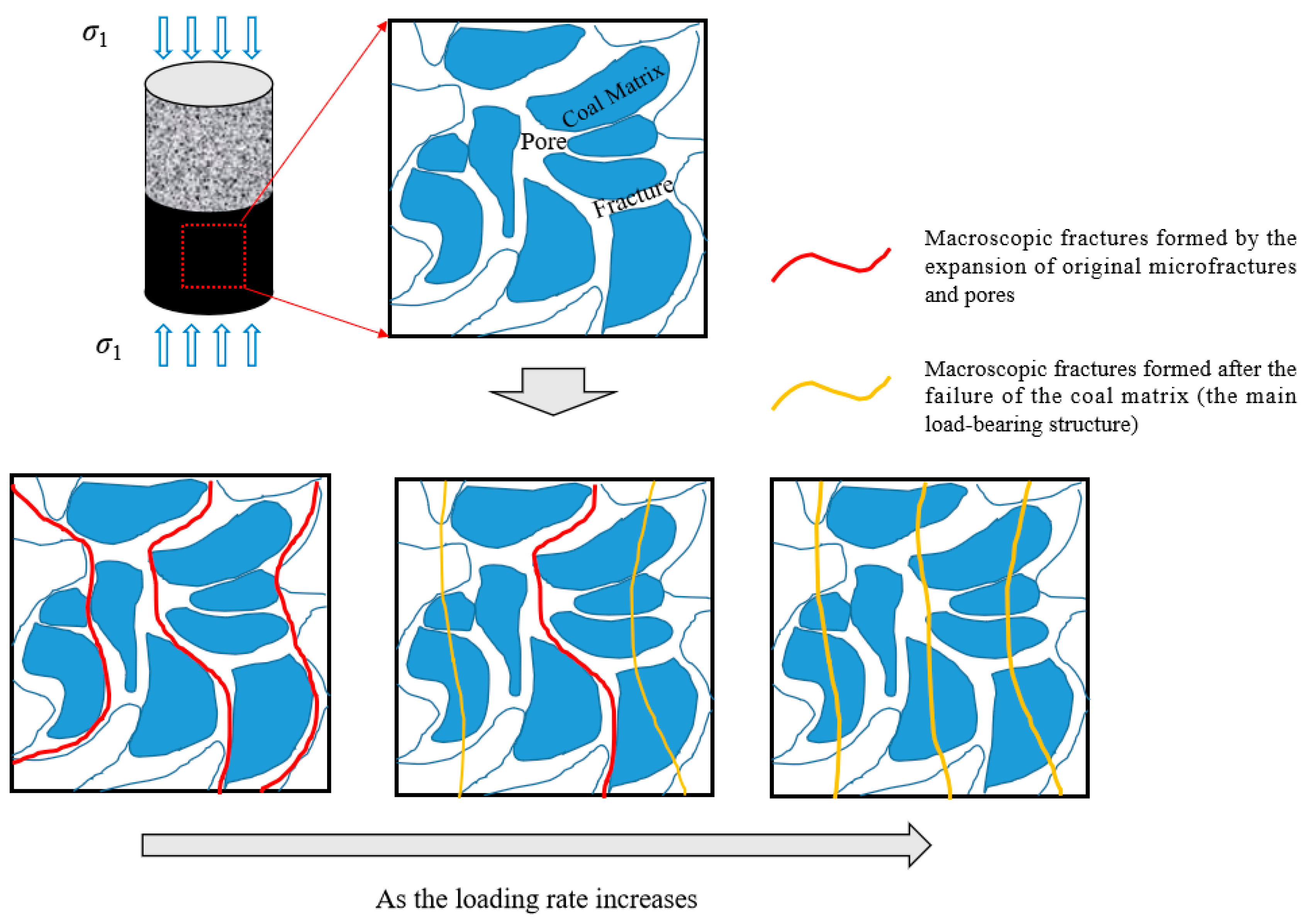
The formation of the above characteristics is caused by the “competition” between fracture propagation and coal matrix failure when the coal component in the coal–rock combination body is deformed under stress (as shown in Figure 15). When the loading rate (or unloading rate) is low, the development and propagation of fractures have sufficient time, resulting in a large total number of fracture events. Therefore, the macroscopic mechanical properties exhibit low compressive strength, small elastic modulus, high energy dissipation degree, and low energy accumulation degree. As the loading rate (or unloading rate) increases, the development and propagation of fractures become insufficient, and the total number of fracture events decreases. The coal matrix, acting as a skeleton, exerts an obvious load-bearing effect. Thus, the macroscopic mechanical properties show increased compressive strength, increased elastic modulus, low energy dissipation degree, and high energy accumulation degree. However, when the loading rate (or unloading rate) further increases, although the development and propagation of fractures remain insufficient, the load-bearing capacity of the coal matrix skeleton cannot meet the deformation requirements under this loading intensity, leading to its failure. As a result, the total number of fracture events increases instead, and the macroscopic mechanical properties exhibit decreased compressive strength, decreased elastic modulus, and the emergence of impact failure effects.
In addition, two more points need to be discussed emphatically to enhance the rigor of the research conclusions in this paper: (1) During the loading process of the coal–rock combination, due to the difference in lateral deformation between coal and rock, friction occurs at the coal–rock interface. A portion of heat is consumed by the work performed by friction, and the viscous damping of coal and rock during deformation also causes a certain amount of heat consumption. By reviewing the relevant literature [35,36] and combining the experimental conditions of this paper, the order of magnitude of this heat consumption is estimated to be 10−1 J. Combined with the experimental results of this paper, the impact of this part of heat on the result analysis in this paper is negligible, and it is feasible to calculate the input energy, elastic energy, and dissipated energy using Formula (5). (2) Properties such as the interface thickness and stiffness of the coal–rock combination have a significant impact on its overall mechanical properties [37]. The coal–rock combinations in this paper are all bonded with marble glue, and the interface properties are fixed influencing factors, so they will not affect the research results.

5. Conclusions

  • The uniaxial compressive strength and elastic modulus of the coal–rock combination body show a variation law of first increasing and then decreasing with the increase in loading rate, while the degree of impact failure significantly increases gradually as the loading rate rises. The post-peak residual elastic energy density of the coal–rock combination body increases gradually with the increase in loading rate, which indicates that the post-peak residual elastic energy density of the coal–rock combination body has a positive correlation with its impact failure effect.
  • The formation of the advancing speed effect of mining-induced stress concentration and elastic energy accumulation in coal–rock masses is caused by the “competitive” interaction between fracture propagation and coal matrix damage when the coal component in the coal–rock combination is deformed under stress.
  • During low-speed advancing, the loading rate is relatively low, providing sufficient time for the development and propagation of fractures. Consequently, the macroscopic mechanical properties are characterized by low compressive strength, small elastic modulus, high energy dissipation, low energy accumulation, minimal energy release during failure, and a weak impact failure effect.
  • The proposed mechanism is consistent with the observed results. In the case of high-speed advancing, the higher loading rate leads to insufficient development and propagation of fractures. The coal matrix, acting as a framework, exerts a significant load-bearing effect. As a result, the macroscopic mechanical properties exhibit increased compressive strength, larger elastic modulus, low energy dissipation, high energy accumulation, substantial energy release during failure, and a strong impact failure effect.

6. Outlook

All the research in this paper on the mechanical properties, failure modes, acoustic emission characteristics, and energy evolution characteristics of coal–rock composites is based on uniaxial compression tests. However, in the actual environment, coal–rock masses are in a triaxial stress state, and the stress magnitude in each direction changes with the mining of the working face. Therefore, in future research, triaxial compression tests on coal–rock composites under mining-induced stress paths will be conducted to analyze the mechanical properties and energy evolution characteristics of coal–rock composites under different loading and unloading rate conditions. In addition, the sample size needs to be increased to improve the accuracy and reproducibility of the research results.

Author Contributions

Methodology, W.L.; Project administration, S.T. and T.Z. All authors have read and agreed to the published version of the manuscript.

Funding

This research was funded by the National Natural Science Foundation of China (51874281) and the China National Natural Science Foundation Youth Funding Project (52004270).

Institutional Review Board Statement

Not applicable.

Data Availability Statement

The data presented in this study are available in the article.

Conflicts of Interest

The authors declare no conflicts of interest.

References

  1. Li, W.L.; Tu, S.H.; Tu, H.S.; Liu, X.; Miao, K.J.; Zhao, H.B.; Ma, J.Y.; Tang, L.; Li, Y. A new method to assess thick, hard roof-induced rock burst risk based on mining speed effect on key energy strata. Sustainability 2022, 14, 15054. [Google Scholar] [CrossRef]
  2. Li, W.L.; Tu, S.H.; Hao, D.Y.; Liu, X.; Miao, K.J. Influence of mining speed and filling ratio on energy accumulation and release of thick and hard roof in deep backfilling working face. J. China Univ. Min. Technol. 2021, 50, 498–506. [Google Scholar]
  3. Li, W.L.; Tu, S.H.; Zhao, T.B. Study on the tensile failure characteristics and energy calculation model of coal seam hard roof considering the mining speed. Appl. Sci. 2024, 14, 5734. [Google Scholar] [CrossRef]
  4. Li, H.T.; Song, L.; Zhou, H.W.; Song, F. Experimental study of nonlinear evolution mechanism of coal strength under multi-loading rates and its application. Chin. J. Rock Mech. Eng. 2016, 35, 2978–2989. [Google Scholar]
  5. Wu, P.; Chen, L.; Chen, Y.L.; Mao, X.B.; Pu, H.; Zhang, K.; Wang, X.F.; Zhang, W. Experimental study on mechanical properties and microcrack fracture of coal specimens under the coupling of loading rate and compression-shear loads. Int. J. Geomech. 2022, 22, 04022028. [Google Scholar] [CrossRef]
  6. Feng, K.W.; Wang, K.Q.; Zhang, D.M.; Yang, Y.S. Experimental study on mechanical properties and seepage laws of raw coal under variable loading and unloading rates. Geofluids 2021, 2021, 5596858. [Google Scholar] [CrossRef]
  7. Zhang, M.B.; Cui, L.; Hu, W.J.; Du, J.L.; Zhang, Z.; Wang, C.L. Acoustic emission experimental research of the damage characteristics of raw coal under different loading and unloading rates. Shock Vib. 2020, 2020, 9063929. [Google Scholar] [CrossRef]
  8. Xiong, Z.Y.; Zhang, D.M.; Lu, J.; Wang, C.Y.; Chen, Y.; Zhang, Y. Mechanical behavior and acoustic emission characteristic response of Macaowan coal samples under different loading rates. Phys. Fluids 2025, 37, 027195. [Google Scholar] [CrossRef]
  9. Liu, B.; Zhao, Y.X.; Hua, X.Z.; Ling, C.W.; Wang, X.L. Failure characteristic and acoustic emission spatio-temporal evolution of coal under different cyclic loading rates. Energy Sci. Eng. 2023, 11, 2039–2051. [Google Scholar] [CrossRef]
  10. Liu, B.; Sun, X.; Ling, C.W.; Huang, Z.J.; Zhang, H.W. Mechanical behaviors and acoustic emission fractal characteristics of bump-prone coal under different loading rates. Fractal Fract. 2023, 7, 45. [Google Scholar] [CrossRef]
  11. Liu, X.W.; Chen, H.X.; Liu, B.; Deng, W.; Liu, Q.S.; Zhang, Z.Z. Experimental and numerical study on failure characteristics and mechanism of coal under different quasi-static loading rates. Theor. Appl. Fract. Mech. 2022, 121, 103478. [Google Scholar] [CrossRef]
  12. Zhu, C.Q.; Li, S.B.; Luo, Y.; Guo, B. Progressive damage process and failure characteristics of coal under uniaxial compression with different loading rates. Shock Vib. 2021, 2021, 3360738. [Google Scholar] [CrossRef]
  13. Liu, Y.C.; Ding, L.; Zhao, Y.F.; Fan, Y.; Li, H.F. Experimental investigations on charge induction and microseismic characteristics of the coal and rock under different loading rates. Shock Vib. 2021, 2021, 6242075. [Google Scholar] [CrossRef]
  14. Li, G.W.; Lu, S.F.; Liu, S.F.; Liu, J.; Shi, P.; Fan, B.W. Application and effect of loading rates on coal sample failure. Shock Vib. 2021, 2021, 6681082. [Google Scholar] [CrossRef]
  15. Zhou, C.; He, X.Q.; Song, D.Z.; Li, Z.L.; Yang, H.K.; Liu, Y.; Guo, L. Study on signal characteristics of burst tendency coal under different loading rates. Int. J. Coal Sci. Technol. 2024, 11, 73. [Google Scholar] [CrossRef]
  16. Li, H.T.; Zhou, H.W.; Jiang, Y.D.; Wang, H.W. An evaluation method for the bursting characteristics of coal under the effect of loading rate. Rock Mech. Rock Eng. 2016, 49, 3281–3291. [Google Scholar] [CrossRef]
  17. Xue, J.H.; Wang, S.L.; Yang, Q.L.; Du, Y.T.; Hou, Z.X. Study on damage characteristics of deep coal based on loading rate effect. Minerals 2022, 12, 402. [Google Scholar] [CrossRef]
  18. Jing, C.; Ji, X.; Yang, W.; Pang, M.K.; Zhang, T.J.; Pan, H.Y. Crack propagation characteristics of coal body around the borehole under different loading rates. Theor. Appl. Fract. Mech. 2024, 133, 104498. [Google Scholar] [CrossRef]
  19. Khan, N.M.; Ma, L.; Cao, K.; Spearing, A.J.S.; Liu, W.; Jie, Y.; Yousaf, M. Early violent failure precursor prediction based on infrared radiation characteristics for coal specimens under different loading rates. Rock Mech. Rock Eng. 2022, 55, 6939–6961. [Google Scholar] [CrossRef]
  20. Li, X.B.; Feng, G.; Xiao, M.L.; Wang, G.F.; Bi, J.; Gao, C.Y.; Liu, H.Z. Experimental study on the effects of loading rates on the fracture mechanical characteristics of coal influenced by long-term immersion in mine water. Appl. Sci. 2025, 15, 8222. [Google Scholar] [CrossRef]
  21. Wang, D.; Ju, F.; Xu, J.; Yan, C.S.; Xiao, M.; Ning, P.; Wang, T.F.; Si, L.; Wang, Y.B. Effects of moisture content and loading rate on coal samples: Mechanical properties and failure mechanisms. Rock Mech. Rock Eng. 2025, 58, 3391–3416. [Google Scholar] [CrossRef]
  22. Wang, S.G.; Elsworth, D.; Liu, J.S. Mechanical behavior of methane infiltrated coal: The roles of gas desorption, stress level and loading rate. Rock Mech. Rock Eng. 2013, 46, 945–958. [Google Scholar] [CrossRef]
  23. Zhang, M.B.; Liu, M.Q.; Zhu, H.Q.; Zhou, D.H.; Wang, L. An experimental study of the damage characteristics of gas-containing coal under the conditions of different loading and unloading rates. J. Loss Prev. Process Ind. 2018, 55, 338–346. [Google Scholar] [CrossRef]
  24. Cao, Y.L.; Hao, J.F.; Sun, W.J.; Su, W.W.; Tian, F.C. Study on temperature evolution law of coal containing gas under uniaxial loading process with different loading rates. Environ. Prog. Sustain. Energy 2024, 44, 14501. [Google Scholar] [CrossRef]
  25. Li, Q.W.; Xu, M.J.; Li, W.X.; Pan, C.C.; Yu, M.M. Energy evolution characteristics and failure mechanism of coal confined by CFRP jackets subjected to different loading rates. Polym. Test. 2025, 143, 108723. [Google Scholar] [CrossRef]
  26. Khan, N.M.; Ahmad, M.; Cao, K.W.; Ali, L.; Liu, W.; Rehman, H.; Hussain, S.; Rehman, F.U.; Ahmed, T. Developing a new bursting liability index based on energy evolution for coal under different loading rates. Sustainability 2022, 14, 1572. [Google Scholar] [CrossRef]
  27. Ma, Q.; Tan, Y.L.; Liu, X.S.; Zhao, Z.H.; Fan, D.Y.; Purev, L. Experimental and numerical simulation of loading rate effects on failure and strain energy characteristics of coal-rock composite samples. J. Cent. South Univ. 2021, 28, 3207–3222. [Google Scholar] [CrossRef]
  28. Huang, B.X.; Liu, J.W. The effect of loading rate on the behavior of samples composed of coal and rock. Int. J. Rock Mech. Min. Sci. 2013, 61, 23–30. [Google Scholar] [CrossRef]
  29. Chen, G.B.; Zhang, J.; Xu, Y.J.; Li, T.; Wang, E.; Zhang, G.H. The influence of loading rate on accumulated energy distribution in coal-rock samples and their failure behavior. J. Min. Sci. 2025, 60, 792–807. [Google Scholar] [CrossRef]
  30. Zhao, S.K.; Deng, Z.G.; Ji, W.B.; Li, Z.G.; Zhang, G.H.; Li, Y.Z. Effects of multi-stage tectonic movement on regional tectonic stress characteristics and rockburst. J. Min. Saf. Eng. 2019, 36, 306–314. [Google Scholar]
  31. Shen, Z. Experimental Study on Characteristics of Acoustic Emission and Fractal in Rock. Master’s Thesis, Chengdu University of Technology, Chengdu, China, 2017. [Google Scholar]
  32. Ma, Y.A.; Ya, C.; Li, H.B.; Liang, Z.Q.; Liu, Y.Q.; Li, S.J. Experimental study on the mechanical properties and energy dissipation of granite during the fracturing process. Chin. J. Rock Mech. Eng. 2025, 44, 1313–1325. [Google Scholar] [CrossRef]
  33. Hashiba, K.; Okubo, S.; Fukui, K. A new testing method for investigating the loading rate dependency of peak and residual rock strength. Int. J. Min. Sci. Technol. 2006, 43, 894–904. [Google Scholar] [CrossRef]
  34. Gao, M.Z.; Xie, J.; Gao, Y.N.; Wang, W.Y.; Cong, L.; Yang, B.G.; Liu, J.J. Mechanical behavior of coal under different mining rates: A case study from laboratory experiments to field testing. Int. J. Min. Sci. Technol. 2021, 31, 825–841. [Google Scholar] [CrossRef]
  35. Yi, Z.Q.; Yin, Y.P.; Li, S.D.; Wang, W.P.; Zhang, M.Z.; Mao, T.Q.; Zhang, Y.X.; Wang, X.B.; Gao, S.H. Research on short-term prediction precursors of bedding-layered sandstone based on strain monitoring. Eng. Fract. Mech. 2025, 320, 111071. [Google Scholar] [CrossRef]
  36. Lyu, X.F.; Chen, Y.L.; Liao, S.M.; Fernandez-Steeger, T.M. Theoretical and numerical analyses of thermal stresses and temperature variations in disc cutter cutting composite strata under thermal-force multi-fields. Case Stud. Therm. Eng. 2024, 61, 105104. [Google Scholar] [CrossRef]
  37. Xu, C.; Yang, T.; Wang, K.; Yuan, Y.W.; Guo, L. Influence of primary interface characteristics on mechanical properties and damage evolution of coal-rock combination. Eng. Fail. Anal. 2024, 164, 108658. [Google Scholar] [CrossRef]
Figure 1. Sample preparation process.
Eng 06 00287 g001
Figure 2. Test system.
Eng 06 00287 g002
Figure 3. The main experimental procedure.
Eng 06 00287 g003
Figure 4. Stress–strain curve of uniaxial compression.
Eng 06 00287 g004
Figure 5. Uniaxial compression strength and deformation parameters.
Eng 06 00287 g005
Figure 6. Final failure pattern under different loading rates: (a) 0.01 mm/min; (b) 0.03 mm/min; (c) 0.11 mm/min; (d) 0.16 mm/min.
Eng 06 00287 g006
Figure 7. Evolution process of AE characteristic parameters at a loading rate of 0.01 mm/min: (a) Ringing count and cumulative energy; (b) Amplitude and absolute energy.
Eng 06 00287 g007
Figure 8. Evolution process of AE characteristic parameters at a loading rate of 0.03 mm/min: (a) Ringing count and cumulative energy; (b) Amplitude and absolute energy.
Eng 06 00287 g008
Figure 9. Evolution process of AE characteristic parameters at a loading rate of 0.11 mm/min: (a) Ringing count and cumulative energy; (b) Amplitude and absolute energy.
Eng 06 00287 g009
Figure 10. Evolution process of AE characteristic parameters at a loading rate of 0.16 mm/min: (a) Ringing count and cumulative energy; (b) Amplitude and absolute energy.
Eng 06 00287 g010
Figure 11. Distribution of AE RA and AF values at different loading rates: (a) 0.01 mm/min; (b) 0.03 mm/min; (c) 0.11 mm/min; (d) 0.16 mm/min.
Eng 06 00287 g011
Figure 12. Evolution of the number of tensile and shear cracks under different loading rates: (a) 0.01 mm/min; (b) 0.03 mm/min; (c) 0.11 mm/min; (d) 0.16 mm/min.
Eng 06 00287 g012aEng 06 00287 g012b
Figure 13. Evolution process of input energy, elastic energy, and dissipated energy under different loading rates: (a) 0.01 mm/min; (b) 0.03 mm/min; (c) 0.11 mm/min; (d) 0.16 mm/min.
Eng 06 00287 g013aEng 06 00287 g013b
Figure 14. Post-peak residual elastic energy density under different loading rates.
Eng 06 00287 g014
Figure 15. Microfracture patterns of coal components under different loading rates [33].
Eng 06 00287 g015
Table 1. Physical properties of coal–rock combination body.
Sample NumberQuality
/kg
Diameter
/mm
Height
/mm
Density
/kg·m−3
UC-10.36949.67100.211901
UC-20.36749.9799.771877
UC-30.36849.97100.551867
UC-40.36649.62100.081892
Table 2. Mechanical properties of coal-rock combination body under different loading rates.
Loading Rate
/mm·min−1
Compressive Strength/MPaElastic Modulus/GPaPost-Peak Residual Elastic Energy Density
/kJ·m−3
0.0116.91.830.6
0.0319.12.537.0
0.1124.43.346.7
0.1619.42.463.2
Disclaimer/Publisher’s Note: The statements, opinions and data contained in all publications are solely those of the individual author(s) and contributor(s) and not of MDPI and/or the editor(s). MDPI and/or the editor(s) disclaim responsibility for any injury to people or property resulting from any ideas, methods, instructions or products referred to in the content.