Article

Determination of Permanent Deformations of Non-Cohesive Soils in Pavement Structures under Repeated Traffic Load

by
Mate Janos Vamos
1,2,* and
Janos Szendefy
2
1
CDM Smith SE, Darmstädter Str. 63, 64404 Bickenbach, Germany
2
Department of Engineering Geology and Geotechnics, Budapest University of Technology and Economics, Műegyetem rkp. 3, H-1111 Budapest, Hungary
*
Author to whom correspondence should be addressed.
Eng 2024, 5(2), 1067-1084; https://doi.org/10.3390/eng5020058
Submission received: 29 April 2024 / Revised: 24 May 2024 / Accepted: 29 May 2024 / Published: 1 June 2024
(This article belongs to the Section Chemical, Civil and Environmental Engineering)

Abstract

:
One of the main types of distress in pavement structures is rutting, which may also reduce serviceability significantly. Most design methods typically attribute rutting to the asphalt layer alone, proposing that it can be managed by controlling vertical deformation or stress at the subgrade’s top. Furthermore, these methods frequently lack precise measurements for rut depth. On-site measurements show that the majority of permanent deformation occurs in the unbound layers beneath the asphalt; attention should be directed towards these layers. In recent literature, there are calculation methods that account for accumulating strains in soils. However, further investigation is needed regarding the effect of soil properties and the significance of the pavement cross-section. The literature is also somewhat contractionary regarding the origin of permanent deformations. In this research, the residual settlement of soils (base, subbase, and subgrade) under flexible pavement systems was analyzed due to the repeated traffic loads. Rut depths were calculated and analyzed using the High-Cycle Accumulation (HCA) model. The different behaviour in each course of the pavement system is discussed to reveal their contribution to total ruts. The effect of the grain size distribution of the subgrade was analyzed, and its significance on the rutting depths was demonstrated. Standardized pavement cross-sections with different asphalt thicknesses were evaluated, and the calculated settlements of the pavement originating from the ground during the design lifetime are also presented. It is shown that, with the same number of repetitions, the settlements calculated in each traffic load class are proportional to the thickness of the asphalt course. The contribution of the base, subbase, and subgrade courses to the total settlement is also presented for different subgrade types and traffic load classes.

1. Introduction

The goal when designing a pavement is to find the most economical combination of pavement material and thickness by also considering the local climatic and ground conditions in such a way that the pavement is capable of bearing the traffic over its design lifetime without restricting its functionality. One of the main types of distress in pavement structures is rutting. It was revealed in [1] that an approximately 28 mm deep rut will reduce the present serviceability index (PSI) of a relatively new pavement to an unacceptable classification. It is therefore crucial to look at the mechanism, possible reasons, as well as techniques to reduce the rutting in order to offer long service life and safe pavement structures [2], since besides serviceability, rutting is considered a major safety issue for vehicles [3].
According to a recent literature review [2], rutting is considered to be of asphalt concrete origin only. Also, some of the recent studies [4,5,6] focused on the characteristics and properties of the hot mixed asphalt to reduce rutting sensitivity. However, instigations at the AASHTO road test revealed that 68% of the permanent deformations occur not in the asphalt concrete but in the underlying base, subbase, and subgrade layers [7]. In a more recent study [8], comparable findings emerged from on-site assessments, indicating that base and subbase deformations account for 73% to 90% of the overall rut depth. To reduce the rutting sensitivity of pavement structures, the research and calculation method should concentrate on the unbound soil layers instead of the asphalt concrete.
According to a recent review of rutting prediction models [9], there is no widely recognized and documented method for calculating permanent deformations in unbound granular layers (base, subbase courses, and subgrade) beneath asphalt or for determining rut depth. Ref. [10] addressed only the deformation of the granular base course, contradicting the findings of [11]. In other instances [12], the material constants or parameter calibrations are not documented, making these models unsuitable for different boundary conditions. In [13,14], the permanent deformations of the unbound layers were determined using state-of-the-art FE analysis. The material constants were calibrated based on cyclic triaxial laboratory tests. However, both studies used a very low number of cycles (only up to 1000 cycles), which is significantly smaller than the millions of axle repetitions usual in pavement structures. Other calculation methods [15] used a state-of-the-art 3D-FEM analysis to quantify the rutting depth. However, only the AC-layer has a constitutive model to enable calculating permanent deformations. The underlying soils are modelled with the Drucker–Prager soil model, so that no cyclic-induced strain can appear in the soils.
In research focusing on rutting, it is crucial to prioritize methods that assess the permanent deformation of the structural layers due to cyclic loading and account for diverse boundary conditions. Since the literature is somewhat controversial regarding the origin of ruts and the calculation methodology, the residual settlements of the unbound layers in the flexible pavement systems induced by the repeated traffic loads were investigated in this paper. The accumulated strains due to cyclic loading were determined using the HCA (High-Cycle Accumulation) model [16]. The theoretical basis of the HCA model is presented in Section 2.1. To calculate the rutting depth, a novel calculation model presented in [17] was used, which is suitable for addressing these problems.
This study aims to elucidate how ruts develop over the design lifetime as a result of axle repetitions. A key focus was to determine the ratio and contribution of each specific unbound pavement layer to the overall rut depth, particularly emphasizing the subgrade, given its natural variability in quality. The research further explores how the grain size distribution characterized by the coefficient of uniformity and mean grain size of the subgrade influences the total rutting of the pavement structure. Additionally, the study examines how selecting different standard cross-sections and pavement thicknesses can affect the serviceability of the pavement. The novelty of this research lies in applying the HCA model for pavement structures. In this way, the behaviour of the different structural layers over the design lifetime and depth under the pavement can be investigated. By analyzing the settlements across different subgrade types and traffic load classes, the study provides insights into the development of rutting and informs strategies for mitigating it through informed design choices.

2. Research Methodology

2.1. Explicit Calculation Method and HCA Model

Implicit methods that directly calculate soil deformations under repeated loading are unsuitable for a large number of cycles. This is because errors in calculation (integration) and material models accumulate with each load cycle, making these methods reliable only for N < 50 cycles [18]. Hence, explicit approaches are preferred for high-cycle loading scenarios, which give the load repetition–accumulated strain ( N ε a c c ) relationship on an empirical basis. One of the most extensively documented material models for evaluating permanent deformations under repeated loads, supported by numerous laboratory tests, is the High-Cycle Accumulation (HCA) model, introduced by [16] and validated in [19]. The model’s detailed presentation is available in [20]; here, only the essential calculation steps pertinent to this research are discussed. If cycles are applied with a low loading frequency, the inertia forces are negligible, leading to quasi-static cyclic loading; at higher frequencies, the loading becomes dynamic due to significant inertia forces. The accumulation model presented in this section based on strain amplitude, is applicable regardless of whether the loading is quasi-static or dynamic. In this research, traffic cyclic loading was considered quasi-static.
The basic principle of the HCA model is to combine the increment-based ( σ ˙ ε ˙ ) advanced implicit material model and the cycle number–accumulated strain ( N ε a c c ) explicit model. In the first step, state parameters such as the void ratio, the mean effective normal stress, the stress state and the cyclic strain amplitude (εampl) are determined with a conventional advanced material model. Subsequently, the strain amplitude serves as input for calculating the rate of strain accumulation using the explicit model (Equation (1)). In drained conditions, if the mean effective normal stress is not changing and no static plastic strains develop, Equation (1) will directly give the plastic strain rate.
ε ˙ a c c = f a m p l f ˙ N f e f p f Y f π
where the following variables are used:
  • ε ˙ a c c is the plastic strain rate per load cycle;
  • f a m p l is the function describing the influence of strain amplitude;
  • f ˙ N is the function describing the preloading history (memory of soil);
  • f e is the function describing the influence of void ratio (density);
  • f p is the function describing the influence of average mean pressure;
  • f Y is the function describing the influence of the average stress ratio;
  • f π is the function describing the influence of polarisation changes.
The permanent deformation resulting from the ΔN cycle package is determined by Equation (2) using the plastic strain rate for a constant strain amplitude, εampl. As soil structure and state parameters undergo long-term changes, the explicit calculation is periodically halted, and the implicit analysis is initiated in control cycles. This process ensures the continuation of explicit calculation for another ΔN cycle package, incorporating the “updated” actual value of εampl.
Δ ε a c c = ε ˙ a c c · Δ N
The HCA model provides the accumulation rate as a vector quantity. Thus, besides the scalar magnitude of the plastic strain, a flow rule is required to define the direction of accumulation (m), delineating the deviatoric εq and volumetric εv components of the strain. These components are instrumental in determining the vertical strain elements essential for settlement analysis.
ε ˙ a c c = ε ˙ a c c m
This study applied the Modified Cam Clay (MCC) flow rule to the subgrade, as suggested by findings from [21]. Tests conducted on crushed stone base course revealed anisotropic behaviour under compaction, unlike sand [22], rendering the MCC flow rule inapplicable. Given that pavements commonly incorporate crushed stone in their base and subbase courses, an anisotropic flow rule based on [22] was adopted for this investigation.
The scalar component of the accumulation rate (Equation (1)) can be calculated as the product of five empirical functions: f a m p l , f ˙ N , f p , f Y , and f e representing the influence of strain amplitude, load history, mean normal stress, average stress ratio, and void ratio, respectively. These factors are described by seven material constants, along with the critical friction angle φ c c , necessary for defining the flow rule and f Y . Notably, φ c c may differ from the critical friction angle φ c obtained from monotonic CU triaxial tests. This study determined φ c c , based on recommendations from [21].
For determining the HCA parameters, a simplified calibration procedure outlined in [23,24] was employed. This procedure was developed for clean subangular quartz sand and gravel soils devoid of fines content, subject to certain constraints: the coefficient of uniformity must fall between 1.5 and 8.0, d50 should range from 0.1 mm to 3.5 mm, and the maximum cycle number should not exceed Nmax = 2 × 10⁶. While the laboratory’s utilization of 2 million cycles represents the upper limit of technical reliability, it surpasses the cycle counts in most literature. However, road pavements may experience a higher number of load cycles. Given the uncertainty regarding soil behaviour beyond 2 × 10⁶ cycles, caution and critical evaluation are warranted for assumptions associated with N > 2 × 10⁶, as the validity of the Ci parameters becomes uncertain. The HCA parameters for the crushed stone base course and subbase course were established following recommendations from [22].
The fN function of the HCA model, which describes the relationship between accumulated residual strain and cycle count, comprises both logarithmic and linear components (Equation (4)). If the logarithmic part of the equation is more pronounced depending on the grain size distribution and grain shape [23], the CN3 factor will be very small, and the equation will appear as a linear line in a semi-logarithmic coordinate system. If the linear part of the equation is more pronounced, the CN3 factor will be relatively large, and the equation will bend upwards in a semi-logarithmic coordinate system.
f N = C N 1 l n 1 + C N 2 N + C N 3 N

2.2. Calculation Method

In this research, a simplified laminar model was used on the analogy of [25,26,27] to calculate the settlement of the pavement. The calculation procedure is discussed in detail in [23]; in this section, only the most important steps are summarized. The used calculation model operates akin to conventional laminar models typically utilized for settlement computations, wherein the subsoil is segmented into multiple sub-layers. Firstly, stress distribution under the axle/wheel load is assessed, and the additional vertical load Δσ1,i in each sub-layer is determined. Subsequently, the cyclic strain amplitude εiampl (averaged from values at the top and base of the sub-layer) is computed at the centerline of each sub-layer, employing a nonlinear approach considering mean normal stress, density, and small strain-dependent stiffness. Next, the accumulated residual strain εiacc is calculated for each sub-layer using εiampl as an input parameter, and compression of each sub-layer is obtained by multiplying it with the thickness and associated cyclic flow rule: s1,iacc = m1 × εiacc di. The principles of the laminar model are summarized in Figure 1. Ref. [23] demonstrates that the simplified procedure provides sufficiently accurate and reliable results for both the resilient and the plastic residual strains. They showed that the difference between settlements given by the simplified and finite element procedures at the end of the design lifetime is approx. 2–7% regardless of the subgrade type and the traffic load class.

2.3. Analyzed Pavement Structure

The aim of this study was to ascertain the accumulated residual strains in the standardized pavement cross-sections outlined in [28] resulting from the repeated passage of a standard axle. These standardized pavement cross-sections, detailed in Table 1, consist of four layers: a sand and gravelly sand subgrade course, a granular subbase course, a crushed stone base course, and an asphalt course. The subgrade comprises quartz sand and gravelly sand with subangular particles, as illustrated in Figure 2, and is assumed to possess a relative compaction of R.C. = 93%. A 200 mm thick subbase course overlays the subgrade, the material of which is extensively discussed in the thesis by [29], with its particle size distribution depicted in Figure 2 as well. It is presumed that the subbase course attains a relative compaction of R.C. = 95%. The bearing capacity (E2), modulus of the subbase material, estimated at approximately 150 MPa based on finite element calculations [30], suggests an E2,m of 60 MPa atop the subbase. Literature data on the HCA parameters of crushed stone base courses is only available for crushed stone bases that comply with Colombian Highway Specifications, which is in very close agreement with international crushed stone base course specifications, so this material was chosen in the tests of this research. It is assumed that the crushed stone has a relative compaction of R.C. = 96% and a uniform thickness of 200 mm (Table 1). Bearing capacity (E2) modulus of the crushed stone material based on finite element calculation [30] is approx. 230 MPa; thus, an E2,b of 120 MPa can be expected on top of the base course, which complies with the international practice of highway construction. The base course is overlain by an asphalt course of traffic load class-dependent thickness (Table 1).
The first step in the traditional empirical-based pavement design approach is to determine the design traffic and select the corresponding design traffic class. The design traffic, F100, is defined as the number of passing standard axles (mass of 10 tons). Axle loads that differ from this are converted to the standard axle load using load factors that are defined depending on the vehicle class (buses, articulated buses, heavy trucks, trucks with trailers and semi-trailers). In this research, the analysis was performed using the mean value of the design traffic ranges given in Table 1.

2.4. Analyzed Soils and Their Properties
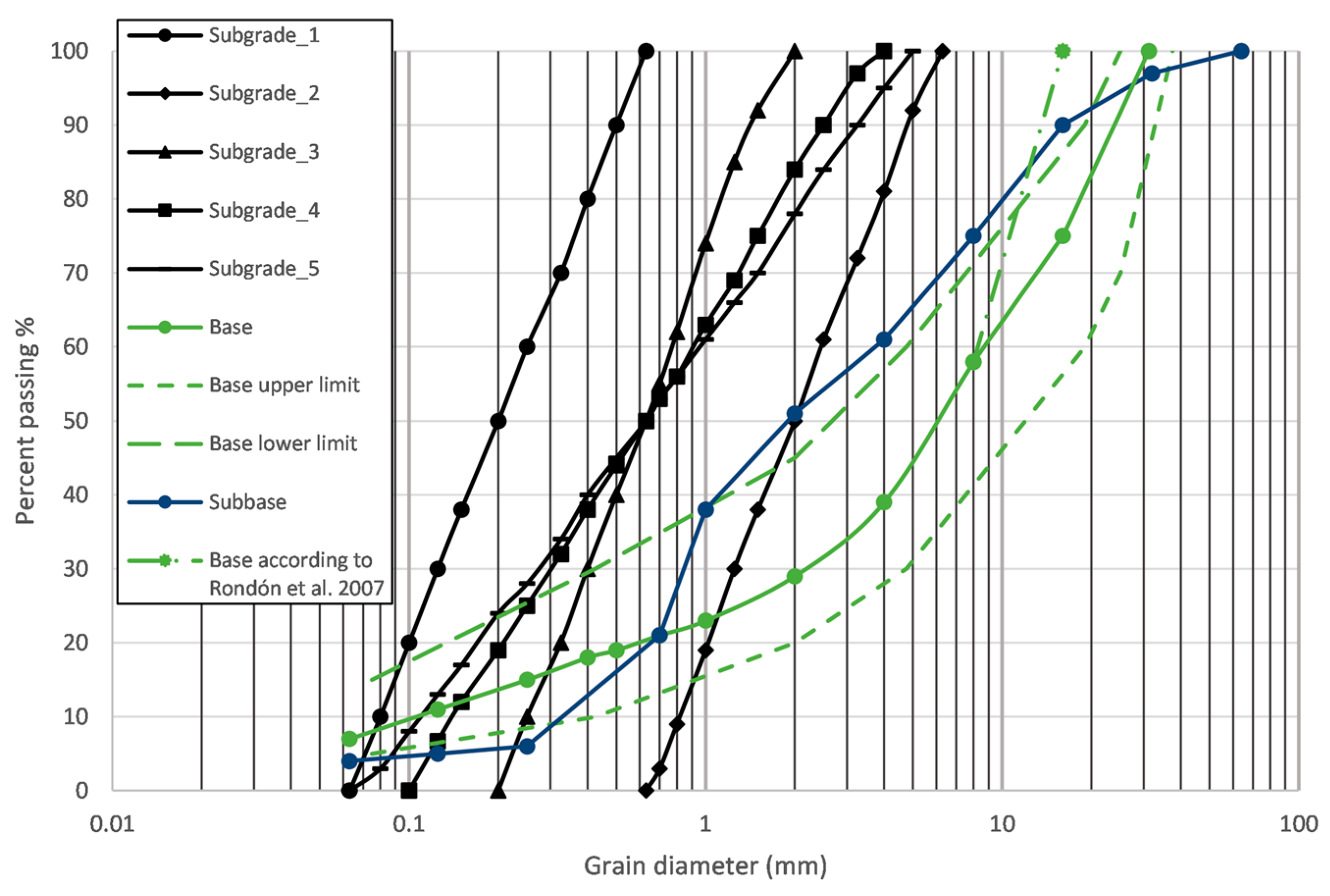
The subgrade was assumed to be composed of sand and gravelly sand soils. The reason behind this is that reliable data on HCA parameters in the literature are mostly available for these soils. Five different types of subgrades were analyzed, which cover well the spectrum of soils for which the simplified calibration procedure presented in [23,24] can be used. The effect of mean diameter, d50, was investigated on Subgrade 1, 2 and 3, where the value of mean diameter was changed while keeping the coefficient of uniformity constant (CU = 3). The mean diameter for the three subgrades was 0.2 mm, 2.0 mm and 0.6 mm, respectively. The effect of the coefficient of uniformity was investigated on Subgrades 3, 4 and 5, where the value of the coefficient of uniformity was varied between CU = 3.0–5.0–8.0 while keeping the mean diameter constant (d50 = 0.60). Grain size distribution curves of the subgrades are presented in Figure 2. Because no Proctor test was available for the subgrade, ρdmax was defined in such a way that the actual void ratio should be e = 0.95emin at 100% modified Proctor compaction following the recommendation of [20]. The small-strain shear stiffness, Gmax, and the maximum oedometer modulus, Mmax, were determined using the correlation in [31,32] as a function of d50 and Cu. The backbone curve was determined using the correlations of [33] as a function of Cu. The material of the subbase was defined according to [29] and the parameters of the crushed stone base were taken from [22,34]. The particle size distribution of the analyzed layers is shown in Figure 2, whereas their properties are summarized in Table 2.
Figure 2. Particle size distribution of the pavement layers [34].
Eng 05 00058 g002
The asphalt course was regarded as a uniform layer, its characteristics defined by thickness, Young’s modulus, and Poisson’s ratio dependent on the traffic load class. The asphalt stiffness was assumed constant (Ea = 4000 MPa, υa = 0.35), adjusted according to the equivalent temperature [35].
The HCA parameters for the subgrade were determined via the correlations established in [23,24] based on d50 and CU. The input parameters for the crushed stone were determined considering the tests of [22]. Because no data are available in the literature for the HCA parameters of the subbase course, the Ci parameters were partly determined by iteration considering the particle size distribution, particle shape and available laboratory test results and literature data [20,22,23,24]. The analysis utilized HCA parameters, which are outlined in Table 3 for reference.

3. Results and Discussion

3.1. Distribution of Strains

The accumulated residual strains caused by traffic loading along the wheel axis were computed for the base, subbase, and subgrade across five distinct subgrades and seven standard pavement cross-sections. This computation was conducted using the calculation model outlined in Section 2. The cyclic loading is constant throughout the entire loading period and is equal to the standard axle load. The numbers of cycles were determined as the average values from the design traffic ranges provided in Table 1. Due to the fact that the HCA parameters were only calibrated up to 2 million cycles, it is not known whether they are still valid above this range or not; the results in traffic load classes “E”-“K”, and “R” should be treated cautiously above this threshold value. Therefore, results above 2 million cycles are shown with dashed lines in the figures.
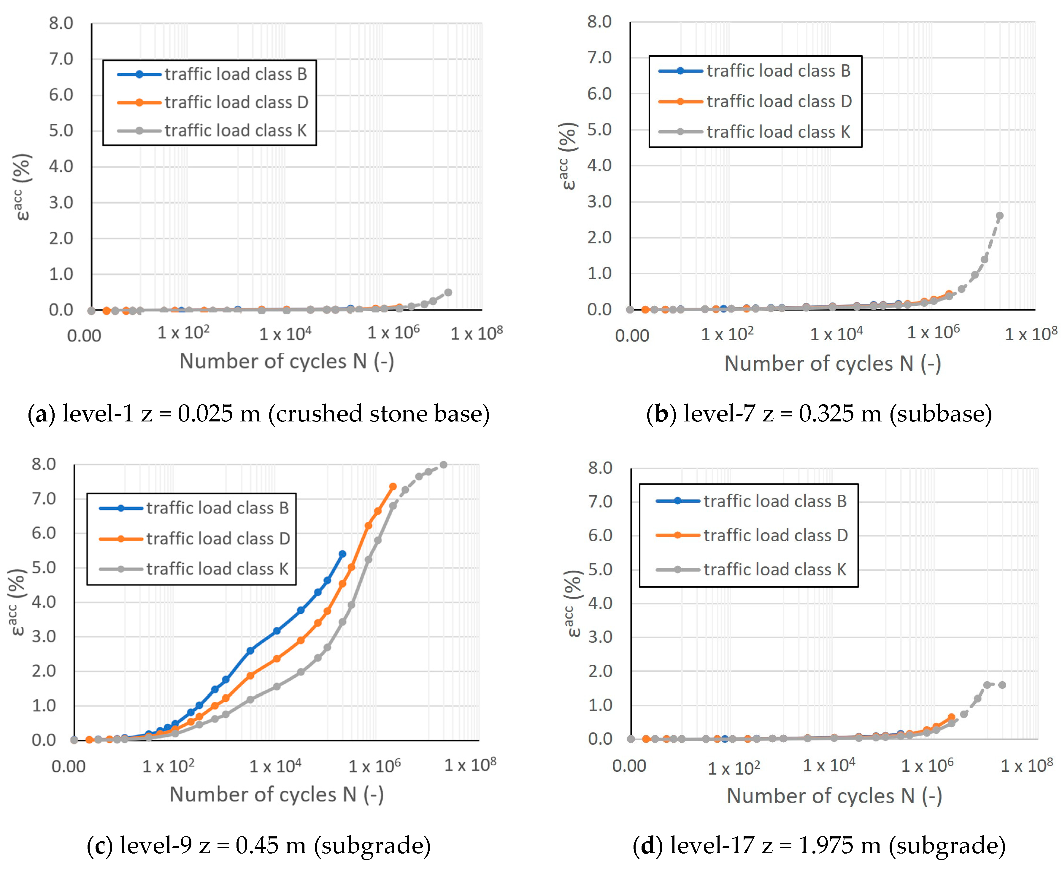
First, let us examine the εacc-N relationship in the most important level for “Subgrade-5” and traffic load classes “B”-“D”-“K”. The most important levels were considered to be at the top of the crushed stone base (level-1), the lower part of the subbase (level-7) and the top of the subgrade (level-9). In order to present the difference between the behaviour of the subgrade and subbase, a level has also been picked from a greater depth (level-17, z = approx. 2 m) where the residual accumulated strain is roughly equal to that of the subbase. The selected levels are shown in Figure 3, whereas the calculated accumulated strains are shown in Figure 4. The scaling of the axes in Figure 4 was chosen to be the same so that the results can be compared more easily; hence, the differences are more visible.
Figure 4 shows that the accumulated strains in the base course are very minor, they are an order of magnitude smaller than the strains in the subbase and subgrade courses. The largest strains, develop in the topmost level (level-9) of the subgrade (Figure 4c). An interesting tendency that is only observed in the subgrade can be noticed here that the rate of accumulation starts to decrease in semi-logarithmic scale after approx. 650,000 cycles. The reason behind this is that due to the large residual strains (5–8%), the subgrade is compacted significantly, and the particles are rearranged In such a dense structure that further compaction is hardly achievable. This appears in the equation of the HCA model in such a way that the new and significantly smaller void ratio e resulting from the volumetric portion of the residual strain (εv) becomes very close to the Ce parameter, which is the void ratio corresponding to the densest state. Consequently, fe becomes ~0, thus ε ˙ a c c is significantly reduced, i.e., the rate of accumulation decreases. On the other hand, the stiffness increases as the void ratio decreases, so the resilient cyclic strain amplitude εampl obtained by the implicit part of the calculation decreases, which also reduces the accumulation rate ε ˙ a c c through fampl.
Comparison of level-7 and level-17 shows that strains are very similar in them until approx. 107 cycles in traffic load classes “B”-“D”-“K”, but they exhibit significantly different behaviour in the last cycle package in traffic load class “K”. In the subbase, mostly the linear component of Equation (4) determines the strains due to the very high number of cycles, which results in a concave function in the semi-logarithmic plot. Accordingly, the effect of the N-dependent CN2 component is negligible, and thus CN3 component, which is independent of N, governs the equation. In the subgrade in level-17, however, εampl is already <10−5 in the last cycle package due to the significant compaction, and as a result, further strain accumulation will not occur [20,36]. Although the behaviour in levels 7 and 17 was very similar in the first 107 cycles, by the end of the design lifetime, almost half as much residual deformation developed in level-17 as in level-7.

3.2. The Effect of Subgrade

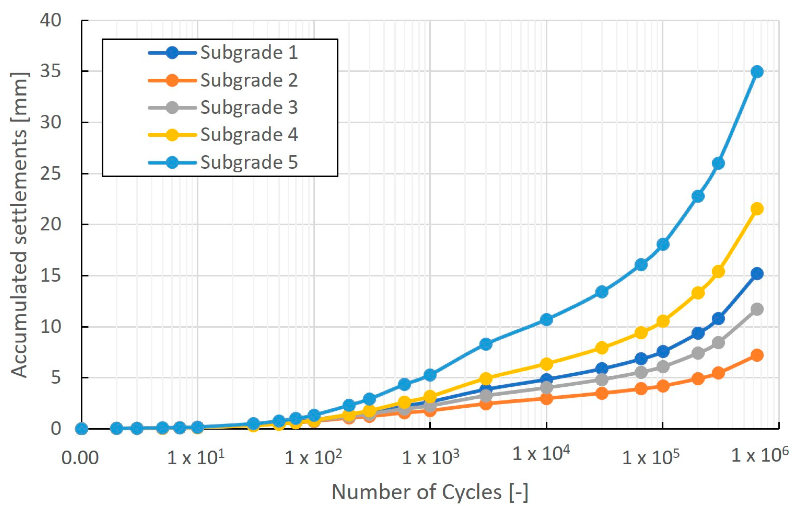
As Figure 4 also shows, the relationship of εacc-N is shaped by very complex processes and depends on several boundary conditions. The goal of this research is to describe the behaviour of the entire unbound part of the pavement system and thus to determine the expected residual settlements. Figure 5 shows the calculated settlements in each type of subgrade for traffic load class “C”. The particle size distribution of the subgrade has a significant effect on the settlement of the whole pavement structure; the difference between the largest and smallest calculated settlements is almost five times. The reason for this is the effect of the Cu and d50 parameters describing the particle size distribution on the CNi HCA parameters.
Let us have a look at the effect of the coefficient of uniformity. For “Subgrade-1”, “-4” and “-5”, the coefficient of uniformity is increased from 3.0 to 5.0 and then to 8.0, respectively, while keeping d50 = 0.6 constant. It is clearly visible that increasing CU increases the settlement. The reason behind this is that more well-graded soils can be compacted better due to a unit of compaction energy because particles of different sizes can fit more easily into the voids between the particles. This appears in the CNi parameters of the HCA model that the difference in, e.g., CN2 and CN3 parameters between “Subgrade-1” and “Subgrade-5” is nearly twofold and in parameter CN1 is nearly threefold. Accordingly, the rate of accumulation in more well-graded soils is high not only in the logarithmic component governing the beginning of loading but also in the linear component governing at higher cycles. The obtained result is a bit surprising at first since, in geotechnical practice, the use of soils with a low coefficient of uniformity is generally avoided because their compaction is difficult at the construction site, and their load-bearing capacity is also lower. Although this statement is true for installation, the opposite conclusion can be drawn if the subsequent compaction due to traffic is considered.
The effect of particle diameter was analyzed In “Subgrade-2”, “-3”, and “-1”, where d50 changes from 2.0 mm to 0.6 mm and then to 0.2 mm, respectively, while CU = 3.0. It can be concluded that strains decrease with increasing particle diameter. The largest strains were calculated in “Subgrade-1”, which has the smallest particle size, and the smallest settlement was obtained in “Subgrade-2”. There is an almost three-fold difference between the calculated settlements. The obtained result is in accordance with the geotechnical practice that soils with larger grain sizes have generally higher strength and load-bearing capacity. This experience is described well by the CNi parameters of the HCA model.
The same tendency was observed for all other traffic load classes as for load class “C” that settlements increase from Subgrade 2–3–1–4 and 5. The total settlements and their ratios in the soils with the extreme values of d50 and CU (“Subgrade-1”-“Subgrade-2” and “Subgrade-1”-“Subgrade-5”, respectively) in each traffic load class are presented in Table 4. As the table shows the subgrade has a fundamental role in the total settlement. The settlement ranges from 2.1 times to 5 times the value for “Subgrade-2” with different coefficients of uniformity and from 1.7 times to 3.2 times the value for “Subgrade-2” with different mean grain sizes. The largest and smallest differences between the effect of subgrades were observed in traffic load class “D” and “R”, respectively. The reason for this is that in the low-traffic load classes, large differences cannot yet emerge from the CN3 parameters due to the relatively low number of axle passes. The effect of the subgrade is the smallest in traffic load classes “K” and “R”. Although it would be possible for the differences arising from the CNi parameters to become distinctive due to the very high number of cycles in these classes, such large strains develop in the subgrade that further strain accumulation is significantly limited by the compaction (see the behaviour in Figure 4c). Accordingly, the subgrade has the greatest effect in the case of load classes “C” and “D”, where the number of cycles is already high enough to trigger the differences in the soil behaviour, but the reduction in the rate of accumulation resulting from compaction only occurs in a thin layer at the top of the subgrade.

3.3. The Effect of Traffic Load Class

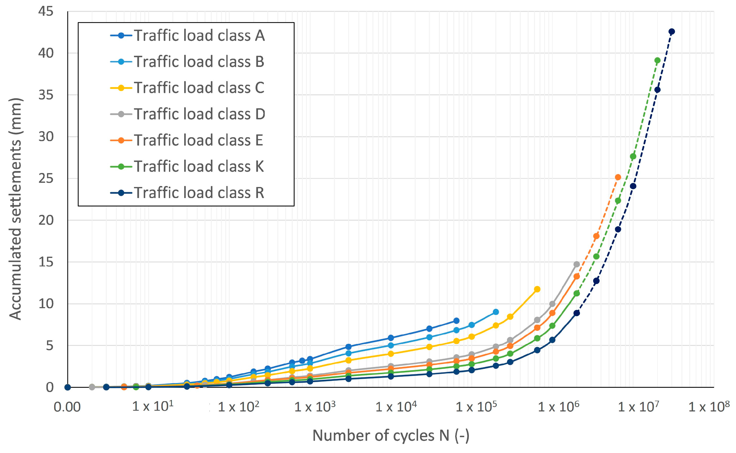
Figure 6 shows the residual settlements as the function of the cycle number for the different traffic load classes in the case of subgrade 3. The figure shows that the logarithmic behaviour is dominant up to approx. 105 cycle number, which appears as a roughly linear line in the semi-logarithmic plot. With the increasing number of cycles and gA-parameter, the logarithmic behaviour becomes more and more overshadowed, and the CN2 component of the HCA equation becomes more and more insignificant. With the further increase in cycle number above 105, the linear component and CN3 parameter become dominant, so the function “curves upwards”, and a concave curve is obtained in a semi-logarithmic plot.
The concept of empirical pavement design, based on traffic load classes, aims to ensure that the stresses induced by varying numbers of axle passes result in equivalent fatigue over the asphalt’s entire design lifespan. However, as depicted in Figure 6, this equivalence does not hold true for settlements. Calculated settlements at the conclusion of the design lifespan escalate with higher traffic load classes. Simultaneously, settlements are observed to be smaller for the same cycle count in higher load classes. This correlation is logical since thicker asphalt courses in higher traffic load classes distribute wheel loads more efficiently, thereby reducing stresses reaching the subgrade and resulting in smaller εampl. Consequently, accumulated strains are lesser in better load-bearing traffic classes for equivalent cycle counts. For instance, after 65,000 axle passes, settlements at the end of the design lifespan are approximately four times greater in traffic load class “A” compared to those calculated for the same cycle count in class “R”. However, by the conclusion of the design lifespan for class “R”, settlements are approximately 5.4 times greater, despite enduring approximately 460 times more axle passes.
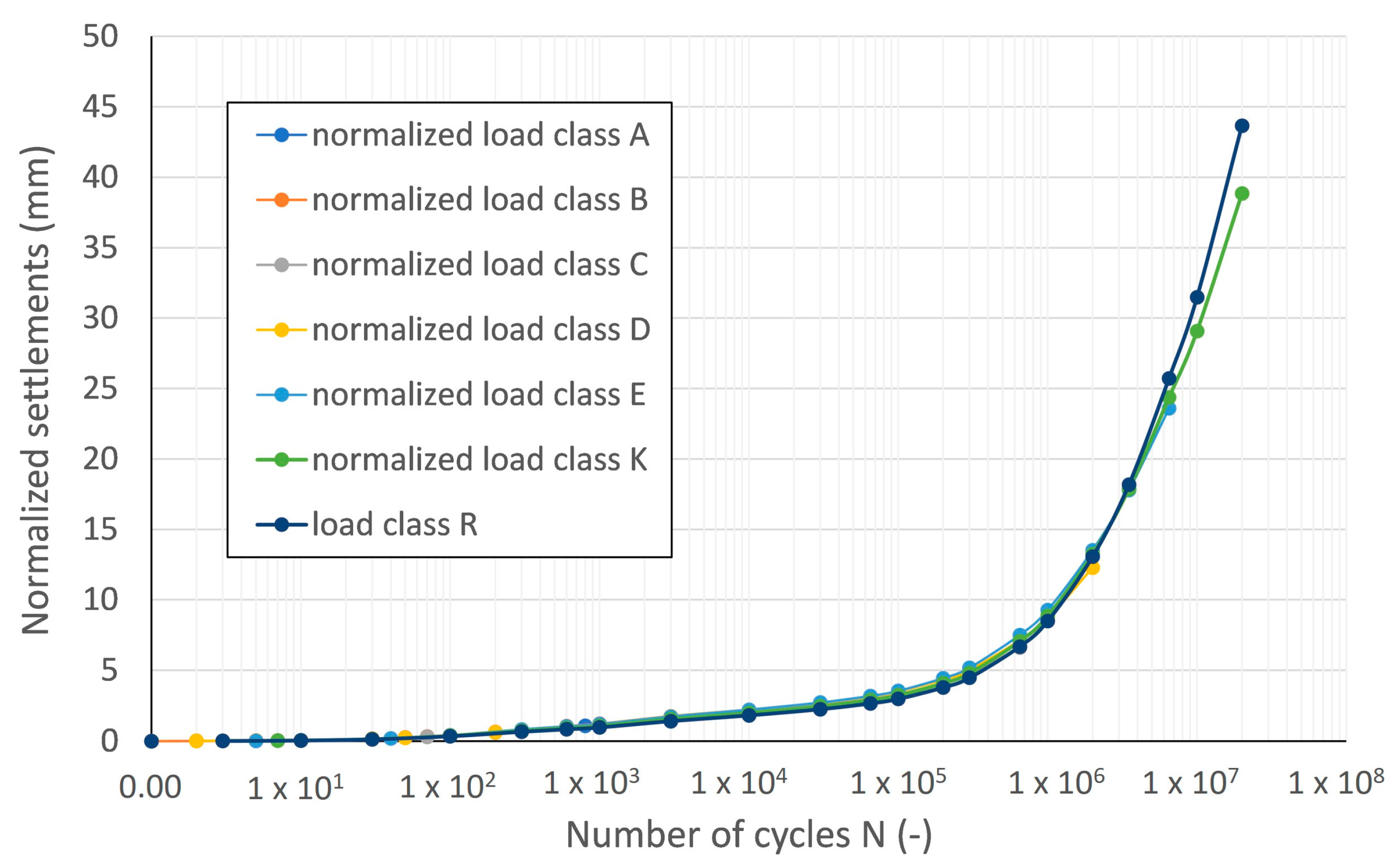
Figure 7 shows the normalized settlements according to Equation (5) in the case of “Subgrade-3”. Accordingly, if the calculated settlement in the ith traffic load class is reduced by the ratio of the asphalt thickness of class “i” and the reference class “R”, the normalized settlement will fall on one curve, which has a variance of s2 = 0.83. This observation is also true for all the other subgrade types. This means that if the boundary conditions (e.g., subgrade type) and the number of cycles are the same, the settlement of the different traffic load classes will be proportional to the ratio of the thickness of the asphalt course as it appears in Equation (5).
S i , n o r m a l i z e d ( N ) = s i ( N ) / d a s p h a l t , i d a s p h a l t , R 1.3

3.4. Ratio of Settlements

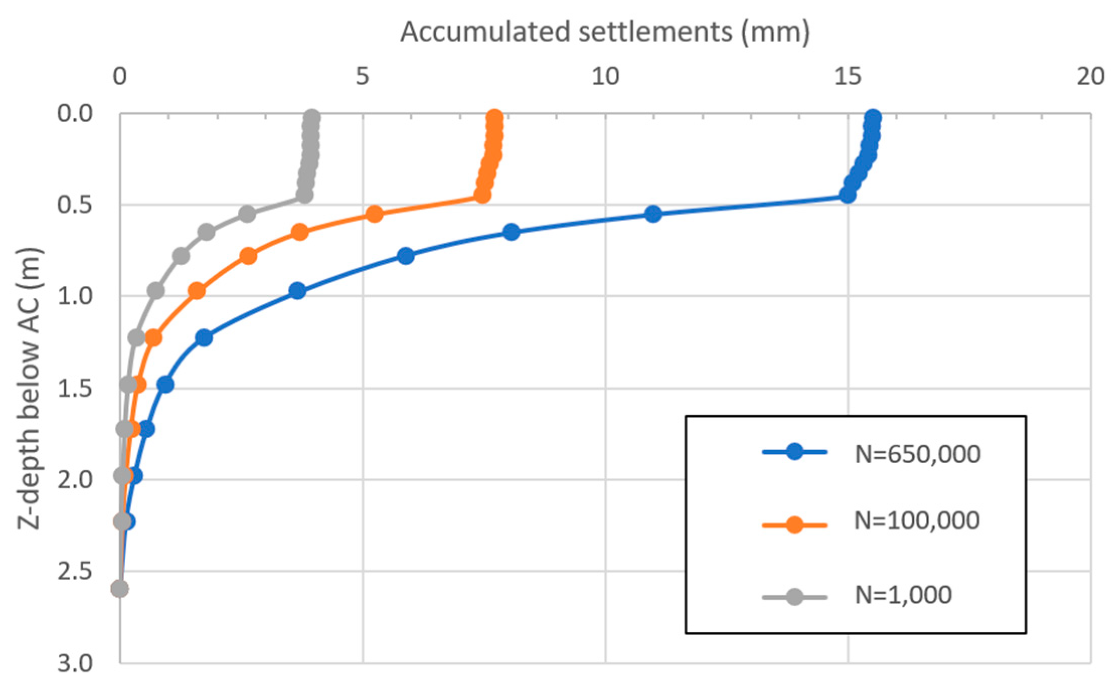
Another important aspect is to determine how each soil layer contributes to the settlement and how the settlement accumulates as a function of depth. This is illustrated in Figure 8 for traffic load class “C” and “Subgrade-1”. Most of the settlement in the selected example (approx. 90%) occurs in the upper approx. 1 m thick zone of the subgrade. The contribution of the base and subbase courses and the deeper zone of the subgrade is marginal to the total settlement.
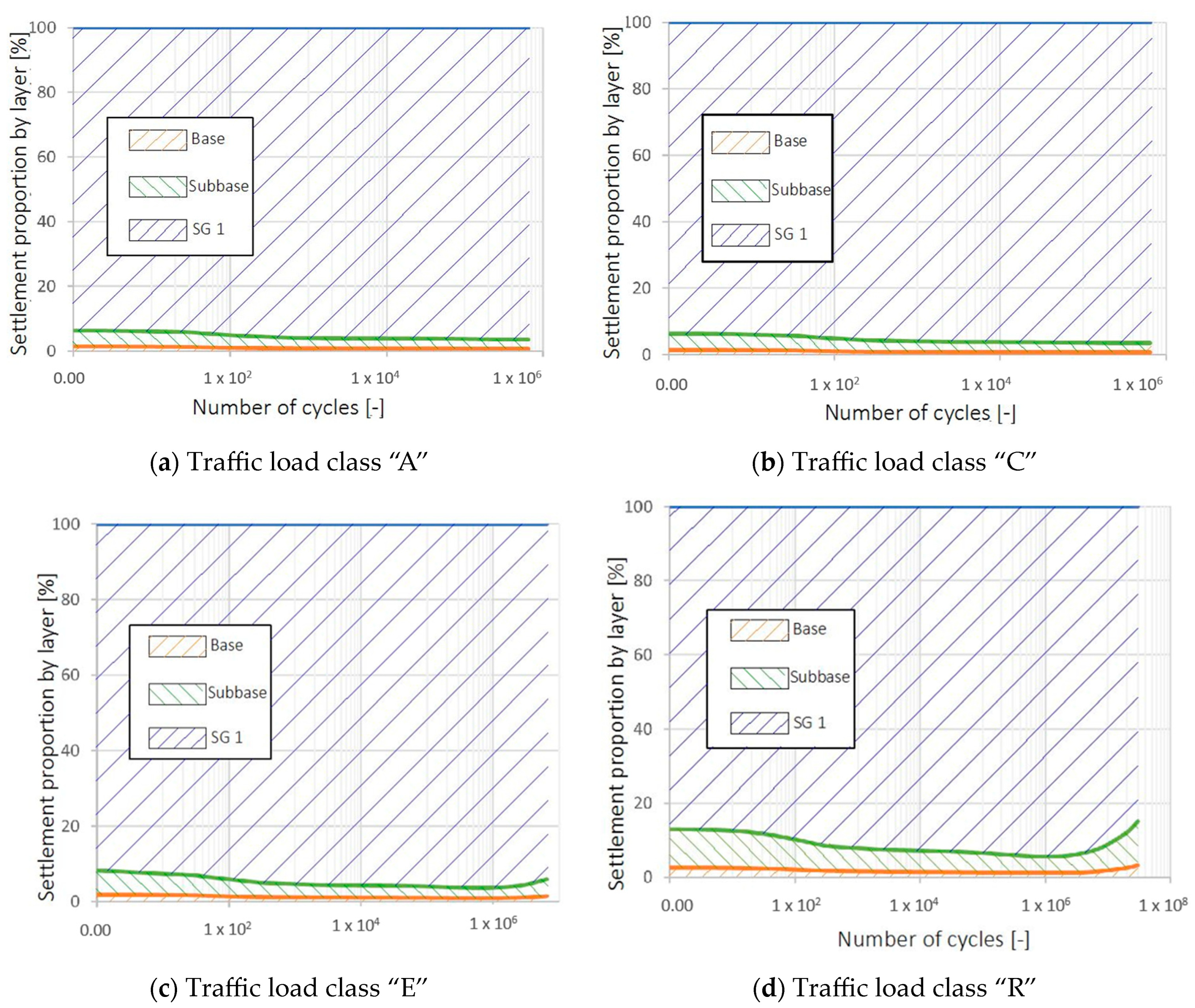
Figure 9 illustrates the percentage contribution of each soil layer to the total settlement as a function of the number of cycles for the different load classes and in the case of “Subgrade 1”. It can be observed that the combined contribution of the crushed stone base course and the subbase course from load classes “A” to “E” is only approx. 5% to the total settlement, and significant deformations develop mostly in the subgrade. This conclusion is true for the entire loading process; the contribution of these layers to the total settlement only changes negligibly (2–4%) with the number of cycles. Generally, in the higher load classes the percentage contribution of the crushed stone and subbase layer is higher in the initial stage of the loading. The reason for this is that the smaller stresses reaching the subgrade result In a smaller εampl, which yields significantly smaller deformations in the subgrade at the beginning of the loading due to the nearly quadratic relationship with Campl. For class “R”, the combined contribution of the crushed stone and subbase gradually decreases from the initial approx. 13% to approx. 6% to 106 cycles, then it increases again to 15% until the end of the design lifetime.
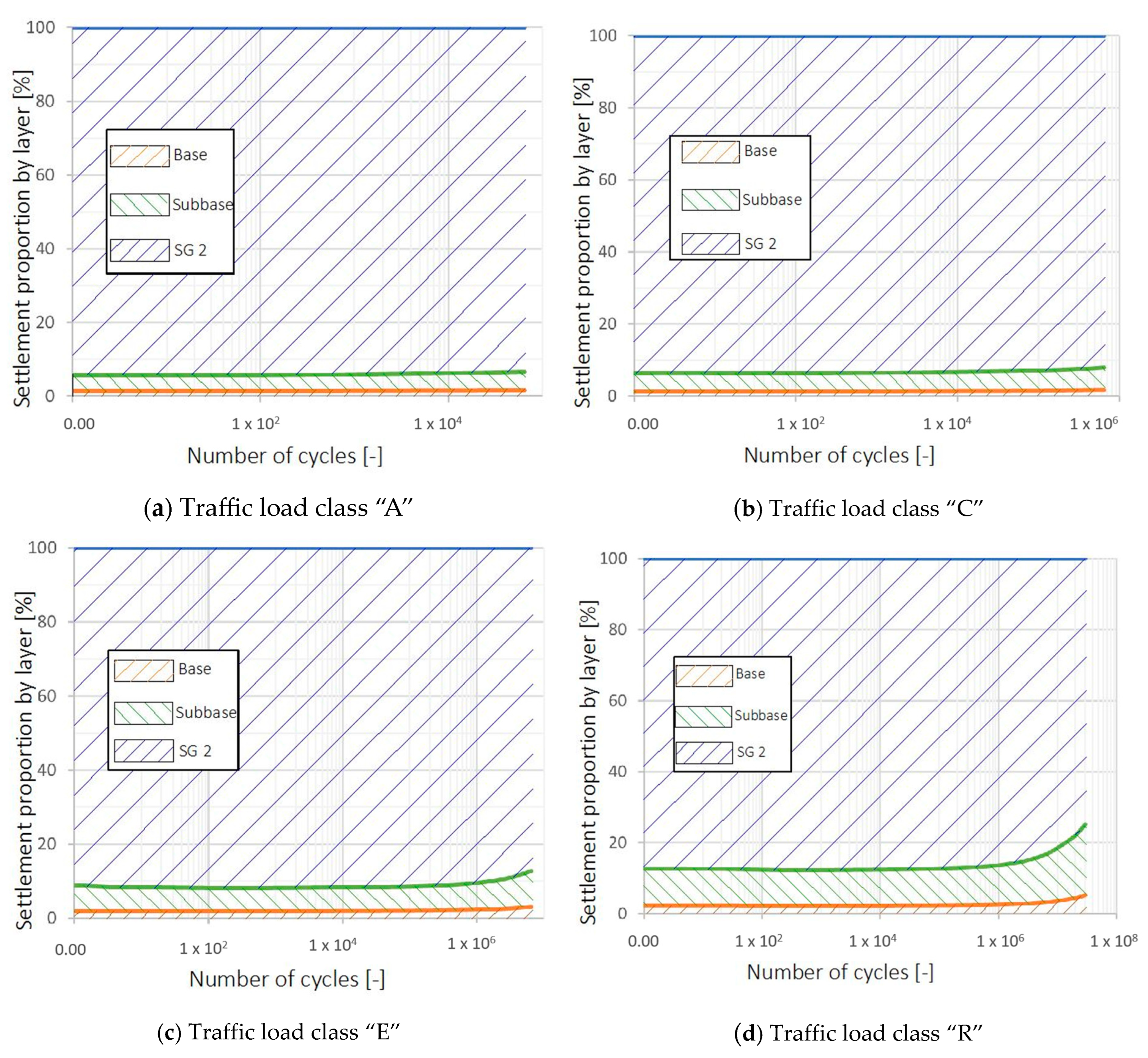
The reason for the shift in the proportions is that the rate of accumulation in the upper coarse-grained layers is more or less constant even at very high cycle numbers, but further strain accumulation is severely limited in the upper part of the subgrade due to the high degree of compaction. Since the rate of accumulation in the subgrade decreases while it remains basically constant in the base and subbase courses, the proportions will shift towards the latter. The general shape of the proportion curves is the same in each traffic load class for the different subgrade types, but the proportions are somewhat different. The reason for this is that “Subgrade-5” is the most sensitive subgrade type, and it can be compacted the most easily, which is why the largest deformations and settlement occur in this type of soil. Since the input parameters for the crushed stone and the subbase layers were not changed, “Subgrade-5” will yield the highest contribution (Figure 10). In the case of “Subgrade-2”, the effect is exactly the opposite; this soil type is the most resistant to cyclic deformations, so the settlement proportion of the crushed stone and subbase layers is higher than for other subgrade types (Figure 11). Accordingly, the extreme values occur in the case of load class “A” with “Subgrade-5” (98% of the settlement is caused by the subgrade) and load class “R” with “Subgrade-2” (75% of the settlement is caused by the subgrade).

4. Conclusions

This study assessed the accumulated residual deformations of soil layers under flexible pavements using both implicit and explicit calculation methods. The research analyzed five types of subgrades with different particle size distributions and seven standardized pavement cross-sections to determine their effects on settlement. The key findings include:
  • Influence of subgrade type: The subgrade grain size distribution characteristic significantly impacts the rutting depth, with well-graded soils showing higher accumulated strains due to better compactability. Increasing the mean particle size (d50) while maintaining a constant coefficient of uniformity (CU) positively affects settlement.
  • Layer contribution: The subgrade accounts for the majority of the total settlement (75–98%), though its contribution decreases towards the end of the design lifetime. Most strains originate in the upper part of the subgrade, suggesting that improving this zone can most effectively reduce rutting.
  • Traffic Load Class: By a given number of load repetitions the accumulated strains will be smaller in the cross sections with thicker asphalt layers due to a better stress distribution. The settlements, however, towards the end of design lifetime, increase with higher traffic load classes and are proportional to the thickness of the asphalt layer when boundary conditions and cycle numbers are constant.
Some of the calculated settlements, especially by higher load classes, are so significant that this probably reduces the serviceability of the pavement before the end of the design lifetime. It was observed that by limiting the vertical deviatoric stress, the settlements can be effectively reduced. This can be achieved via a better stress distribution by using thicker asphalt courses, thicker and stabilized base and subbase courses or by using rigid pavement structures, especially by higher traffic load classes. The calculation method used is well suited for parametric studies, and future research will examine additional factors affecting rutting. Future work will also determine the spatial extent of settlements, consider different national specifications, and investigate the effects of varying load cycles and seasonal temperature changes on asphalt stiffness and settlements. By understanding these factors, we can better predict and mitigate rutting in pavement structures, ultimately improving pavement performance and longevity.

Author Contributions

Conceptualization, M.J.V. and J.S.; methodology, M.J.V. and J.S.; software, M.J.V. and J.S.; validation, M.J.V. and J.S.; formal analysis, M.J.V.; investigation, M.J.V.; resources, M.J.V.; data curation, M.J.V.; writing—original draft preparation, M.J.V.; writing—review and editing, M.J.V.; visualization, M.J.V.; supervision, M.J.V. and J.S.; project administration, M.J.V.; funding acquisition, M.J.V. All authors have read and agreed to the published version of the manuscript.

Funding

This research received no external funding.

Institutional Review Board Statement

Not applicable.

Informed Consent Statement

Not applicable.

Data Availability Statement

The data that support the findings of this study are available from the corresponding author upon reasonable request.

Conflicts of Interest

Mate Vamos is an employee of CDM Smith SE. The authors have not received fundings from CDM Smith. The authors declare that the research was conducted in the absence of any commercial or financial relationships that could be construed as a potential conflict of interest.

References

  1. AASHTO. AASHTO Guide for Design of Pavement Structures; American Association of State Highway and Transportation Officials: Washington, DC, USA, 1993; ISBN 978-1-56051-055-0. [Google Scholar]
  2. Albayati, A.H. A Review of Rutting in Asphalt Concrete Pavement. Open Eng. 2023, 13, 20220463. [Google Scholar] [CrossRef]
  3. Bissada, A.F. Compactibility of Asphalt Paving Mixtures and Relation to Permanent Deformation. Transp. Res. Rec. 1983, 911, 1–10. [Google Scholar]
  4. Bharath, G.; Kakade, V.; Reddy, K.S.; Tandon, V.; Reddy, M.A. Investigation of Rutting Performance of Dense and Gap Graded Recycled Asphalt Mixtures. Innov. Infrastruct. Solut. 2023, 8, 252. [Google Scholar] [CrossRef]
  5. Zhang, J.; Cao, J.; Huang, W.; Shi, X.; Zhou, X. Rutting Prediction and Analysis of Influence Factors Based on Multivariate Transfer Entropy and Graph Neural Networks. Neural Netw. 2023, 157, 26–38. [Google Scholar] [CrossRef]
  6. Aljbouri, H.J.; Albayati, A.H. Effect of Nanomaterials on the Durability of Hot Mix Asphalt. Transp. Eng. 2023, 11, 100165. [Google Scholar] [CrossRef]
  7. Morris, J. The Prediction of Permanent Deformation in Asphalt Concrete Pavements; USA Transport Group: Bensenville, IL, USA, 1973. [Google Scholar]
  8. White, T.D.; Haddock, J.E.; Hand, A.J.T.; Fang, H. Contributions of Pavement Structural Layers to Rutting of Hot Mix Asphalt Pavements; NCHRP Report 468; National Academy Press: Washington, DC, USA, 2002; ISBN 978-0-309-06721-8. [Google Scholar]
  9. Singh, A.K.; Sahoo, J.P. Rutting Prediction Models for Flexible Pavement Structures: A Review of Historical and Recent Developments. J. Traffic Transp. Eng. Engl. Ed. 2021, 8, 315–338. [Google Scholar] [CrossRef]
  10. Werkmeister, S. Permanent Deformation Behaviour of Unbound Granular Materials in Pavement Constructions. Ph.D. Thesis, Technische Universität Dresden, Dresden, Germany, 2003. [Google Scholar]
  11. Powell, W.D.; Potter, J.F.; Mayhew, H.C.; Nunn, M.E. The Structural Design of Bituminous Roads; Transport and Road Research Laboratory (TRRL): Wokingham, Berkshire, UK, 1984. [Google Scholar]
  12. Uzan, J. Permanent Deformation in Flexible Pavements. J. Transp. Eng. 2004, 130, 6–13. [Google Scholar] [CrossRef]
  13. Qi, H.; Zhang, X.; Liu, J.; Zhang, T.; Lv, G.; Cui, L.; Xie, Q. Study on Deformation Characteristics of Low-Highway Subgrade under Traffic Load. Appl. Sci. 2022, 12, 3406. [Google Scholar] [CrossRef]
  14. Zhou, P.; Cui, L.; Zhang, X.; Ma, C.; Liu, J.; Shao, Y.; Lv, G.; Xie, Q. Study on Deformation Characteristics of Extended Highway in Operation Period. Adv. Civ. Eng. 2022, 2022, 5496999. [Google Scholar] [CrossRef]
  15. Leonardi, G.; Suraci, F. A 3D-FE Model for the Rutting Prediction in Geogrid Reinforced Flexible Pavements. Sustainability 2022, 14, 3695. [Google Scholar] [CrossRef]
  16. Niemunis, A.; Wichtmann, T.; Triantafyllidis, T. A High-Cycle Accumulation Model for Sand. Comput. Geotech. 2005, 32, 245–263. [Google Scholar] [CrossRef]
  17. Vamos, M.J.; Szendefy, J. Calculation Method for Traffic Load-Induced Permanent Deformation in Soils under Flexible Pavements. Geotechnics 2023, 3, 955–974. [Google Scholar] [CrossRef]
  18. Niemunis, A. Extended Hypoplastic Models for Soils; Habilitáció, Institutes für Grundbau und Bodenmechanik der Ruhr-Universität Bochum: Bochum, Germany, 2003. [Google Scholar]
  19. Wichtmann, T. Explicit Accumulation Model for Non-Cohesive Soils under Cyclic Loading; Schriftenreihe des Institutes für Bodenmechanik der Ruhr-Universität Bochum: Bochum, Germany, 2005. [Google Scholar]
  20. Wichtmann, T. Soil Behaviour under Cyclic Loading—Experimental Observations, Constitutive Description and Applications; Karlsruher Institut für Technologie Institut für Bodenmechanik und Felsmechanik: Karlsruhe, Germany, 2016. [Google Scholar]
  21. Wichtmann, T.; Niemunis, A.; Triantafyllidis, T. Flow Rule in a High-Cycle Accumulation Model Backed by Cyclic Test Data of 22 Sands. Acta Geotech. 2014, 9, 695–709. [Google Scholar] [CrossRef]
  22. Wichtmann, T.; Rondón, H.; Niemunis, A.; Triantafyllidis, T.; Lizcano, A. Prediction of Permanent Deformations in Pavements Using a High-Cycle Accumulation Model. J. Geotech. Geoenvironmental Eng. 2010, 136, 728–740. [Google Scholar] [CrossRef]
  23. Wichtmann, T.; Niemunis, A.; Triantafyllidis, T. Improved Simplified Calibration Procedure for a High-Cycle Accumulation Model. Soil Dyn. Earthq. Eng. 2015, 70, 118–132. [Google Scholar] [CrossRef]
  24. Wichtmann, T.; Triantafyllidis, T. Inspection of a High-Cycle Accumulation Model for Large Numbers of Cycles (N = 2 Million). Soil Dyn. Earthq. Eng. 2015, 75, 199–210. [Google Scholar] [CrossRef]
  25. Häcker, A. Erweiterung Eines Lamellenmodells für Zyklisch Belastete Flachgründungen (Extension of a Laminal Modell for Cyclic Loaded Foundations); Karlsruher Institute für Technologie, Institute für Bodenmechanik und Felsmechanik: Karlsruhe, Germany, 2013. [Google Scholar]
  26. Wöhrle, T. Überprüfung und Entwicklung Einfaher Ingenieurmodelle für Offshore-Windenerigealagen auf Bass Eines Akkumulationsmodells (Examination and Development of Simplified Engineering Oriented Model for Offshore Wind Turbins on the Basis of an Accumulation Modell); Karlsruher Institute für Technologie, Institute für Bodenmechanik und Felsmechanik: Karlsruhe, Germany, 2012. [Google Scholar]
  27. Zachert, H. Zur Gebrauchstauglichkeit von Gründungen für Offshore-Windenergieanlagen (On the Usability of Foundations for Offshore Wind Turbins). Ph.D. Thesis, Karlsruher Institut für Technologie (KIT), Karlsruhe, Germany, 2015. ISBN 0453-3267. [Google Scholar]
  28. e-UT06.03.13; Aszfaltburkolatú Útpályaszerkezetek Méretezése és Megerősítése E-UT06.03.13 (ÚT 2-1.202). Útügyi Műszaki Előírás: Budapest, Hungary, 2017.
  29. Káli, A. Ipari Padlók Ágyazatként És Útépítési Védőrétegként Használt Durvaszemcsés Talaj Sajátmodulusának Numerikus Modellezése. Bachelor’s Thesis, BME, Budapest, Hungary, 2020. [Google Scholar]
  30. Vámos, M.J.; Szendefy, J. Overconsolidated Stress and Strain Condition of Pavement Layers as a Result of Preloading during Construction. Period. Polytech. Civ. Eng. 2023, 67, 1273–1283. [Google Scholar] [CrossRef]
  31. Wichtmann, T.; Triantafyllidis, T. Influence of the Grain-Size Distribution Curve of Quartz Sand on the Small Strain Shear Modulus Gmax. J. Geotech. Geoenvironmental Eng. ASCE 2009, 135, 1404–1418. [Google Scholar] [CrossRef]
  32. Wichtmann, T.; Triantafyllidis, T. On the Influence of the Grain Size Distribution Curve on P-Wave Velocity, Constrained Elastic Modulus Mmax and Poisson’s Ratio of Quartz Sands. Soil Dyn. Earthq. Eng. 2010, 30, 757–766. [Google Scholar] [CrossRef]
  33. Wichtmann, T.; Triantafyllidis, T. Effect of Uniformity Coefficient on G/Gmax and Damping Ratio of Uniform to Well-Graded Quartz Sands. J. Geotech. Geoenvironmental Eng. 2013, 139, 59–72. [Google Scholar] [CrossRef]
  34. Rondón, H.A.; Wichtmann, T.; Triantafyllidis, T.; Lizcano, A. Hypoplastic Material Constants for a Well-Graded Granular Material for Base and Subbase Layers of Flexible Pavements. Acta Geotech. 2007, 2, 113–126. [Google Scholar] [CrossRef]
  35. Útügyi Lapok Kutatási Jelentés: Tervezési Útmutató: Aszfaltburkolatú Útpályaszerkezetek Méretezésének Alternatív Módszere. 2016. Available online: https://utugyilapok.hu/wp-content/uploads/2015/11/Analitikus-TU.pdf (accessed on 28 April 2024).
  36. Leelantikul, S.; Timmerman, D.H. Deformation of Sand under Cyclic Loading. In Proceedings of the Conference on Soil Dynamics and Earthquake Engineering, Southampton, UK, 13–15 July 1982. [Google Scholar]
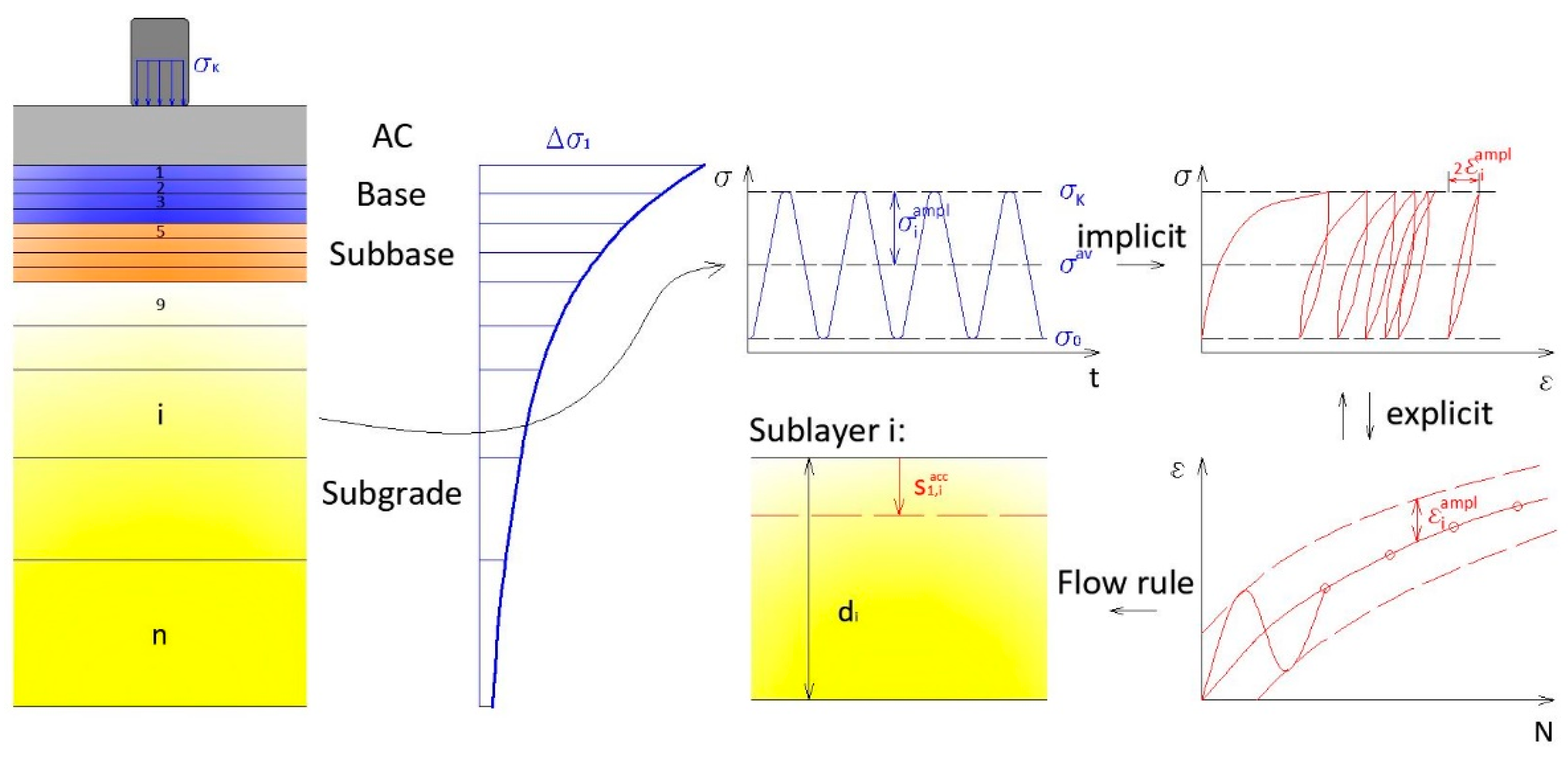
Figure 1. The main calculation steps of the layered model [17].
Eng 05 00058 g001
Figure 3. Location of the 4 selected levels: Level-1 on top of the crushed stone base, level-7 in the middle of the subbase in the depth of z = 0.325 m, level-9 on top of the subgrade, level 17 in the subgrade in the depth of z ~ 2 m.
Eng 05 00058 g003
Figure 4. εacc in the function of load cycles for four selected levels (a) Level-1 on top of the crushed stone base. (b) Level-7 (subbase). (c) Level-9 on top of the subgrade. (d) Level-17 in the subgrade.
Eng 05 00058 g004
Figure 5. The effect of subgrade on settlements in the case of traffic load class “C”.
Eng 05 00058 g005
Figure 6. The relationship between settlement and cycle number in the case of “Subgrade-3”.
Eng 05 00058 g006
Figure 7. Normalized settlements with the thickness of the asphalt.
Eng 05 00058 g007
Figure 8. Distribution of settlement with depth in the case of traffic load class “C” and “Subgrade-1”.
Eng 05 00058 g008
Figure 9. The contribution of each layer to the total settlement as a function of the number of cycles—“Subgrade-1”.
Eng 05 00058 g009
Figure 10. The contribution of each layer to the total settlement as a function of the number of cycles—“Subgrade-5”.
Eng 05 00058 g010aEng 05 00058 g010b
Figure 11. The contribution of each layer to the total settlement as a function of the number of cycles—“Subgrade-2”.
Eng 05 00058 g011
Table 1. Standardized pavement cross-sections according to [28].
Traffic Load ClassDesign Traffic
(Million Axles)
Thickness of Base Course (mm)Thickness of AC-Layer (mm)
A0.03–0.1200100
B0.1–0.3200120
C0.3–1.0200150
D1.0–3.0200180
E3.0–10.0200220
K10.0–30.0200250
ROver 30200290
Table 2. Geotechnical parameters of the layers.
Layerd50
(mm)
CU
(-)
emin
(-)
emax
(-)
ρdmax
(g/cm3)
e0
(-)
υ
(-)
Subgrade 10.23.00.5400.9201.750.6270.33–0.36
Subgrade 22.03.00.4910.7831.810.5770.33–0.36
Subgrade 30.63.00.4740.8291.830.5590.33–0.36
Subgrade 40.65.00.3940.7491.930.4780.35–0.38
Subgrade 50.68.00.3560.6731.980.4390.36–0.40
Subbase2.011.90.3640.5132.060.3400.40
Base6.3100.00.2300.4402.300.1880.40
Table 3. HCA parameters of the layers.
LayerCamplCeCpCYCN1CN2CN3fcc
Subgrade 1 (L26)1.700.5130.472.265.49 × 10−31.30 × 10−22.38 × 10−532.76°
Subgrade 2 (L19)1.700.4660.212.982.11 × 10−32.77 × 10−21.22 × 10−534.73°
Subgrade 3 (L12)1.700.4500.412.603.88 × 10−31.54 × 10−22.05 × 10−533.20°
Subgrade 4 (L14)1.700.3740.412.608.44 × 10−36.72 × 10−33.21 × 10−533.20°
Subgrade 5 (L16)1.700.3380.412.601.53 × 10−25.67 × 10−34.53 × 10−533.20°
Base1.100.070−0.221.805.20 × 10−40.031.30 × 10−544°
Subbase1.100.204−0.221.805.20 × 10−40.031.30 × 10−542°
Table 4. Total settlements and their ratio for subgrades with the lower and upper bound particle size distributions.
Traffic Load ClassTotal Settlement (mm)“Subgrade-5”/“Subgrade-2”“Subgrade-1”/“Subgrade-2”
“Subgrade-1”“Subgrade-2”“Subgrade-5”
A11.05.820.63.61.9
B12.56.425.23.92.0
C15.57.235.04.92.2
D22.89.145.65.03.2
E33.816.156.63.52.1
K47.127.467.52.41.7
R50.432.168.22.11.6
Disclaimer/Publisher’s Note: The statements, opinions and data contained in all publications are solely those of the individual author(s) and contributor(s) and not of MDPI and/or the editor(s). MDPI and/or the editor(s) disclaim responsibility for any injury to people or property resulting from any ideas, methods, instructions or products referred to in the content.