Abstract
Ubiquitous street lighting is essential for urban areas. While nowadays, LED-based “smart lamps” are commercially available, municipalities can only switch to them in the long run due to financial constraints. Especially, older types of lamps require frequent bulb replacements to maintain the lighting infrastructure’s function. To speed up the detection of defects and enable better planning, a non-invasively retrofittable IoT sensor solution is proposed that monitors lamps for defects via visible light sensors, communicates measurement data wirelessly to a central location via LoRaWAN, and processes and visualizes the resulting information centrally. The sensor nodes are capable of automatically adjusting to shifting day- and nighttimes thanks to a second sensor monitoring ambient light. The work specifically addresses aspects of energy efficiency essential to the battery-powered operation of the sensor nodes. Besides design considerations and implementation details, the paper also summarizes the experimental validation of the system by way of an extensive field trial and expounds upon further experiences from it.
1. Introduction
Ubiquitous street lighting is an essential factor in every urban area: it prevents accidents, lowers crime, and contributes to citizens’ perception of safety [1]. Viewing its availability as a given, few people consider the costs and maintenance efforts required to keep it running. Recent developments have resulted in market-ready modern “smart” street lamps with integrated monitoring features that, thanks to utilizing light-emitting diode (LED) bulbs, also have lower defect rates per se. But replacing all street lamps in a given municipality with such lamps comes at a high cost, with estimations of 4500 to 7000 EUR per lamppost for the simplest configuration [2], and is thus infeasible in most cities. Therefore, lamps are only replaced if there are major roadworks or new districts are planned. In [1], the authors study lighting systems in different Italian cities and come to the conclusion that many systems (especially older installations) do not fulfill the safety requirements in terms of provided brightness and are also not sufficiently energy-efficient by today’s standards. The outcome of their work is a tool that allows cities to analyze and refurbish existing systems in order to meet energy and (urban) safety requirements.
However, whether lamps are replaced by newer models or not, there will always be a large variety of lamp designs and lighting options in any practical context. This implies the need for constant monitoring for defects, subsequent repairs, and tracking of lamp configurations. While the latter is carried out as part of documentation of lamp locations and can be seen as lamp metadata, the first point could be handled by retrofittable monitoring solutions based on Internet of Things (IoT) technologies. It is impractical to frequently patrol all of a municipality’s lampposts (especially at night). Without a monitoring system, the other option consists in relying on citizens to notice defects and report these to the administration. However, this is problematic, too, because defects might still be hard to locate exactly without inspection by dedicated personnel due to a lack of fine grained, precise location information, and multiple reports for the same defect may cause confusion. A system that is able to automatically report problems on a per-lamp scale is thus preferable to ensure smooth repairs.
The aforementioned variance in lamp design and technologies poses several challenges for monitoring solutions. Such a monitoring system should be retrofittable and not require interfacing with the lamps’ power supply as that would again require significant costs and efforts. Instead, the system should consist of energy-autonomous sensor nodes communicating wirelessly across a given urban area. The information obtained from the sensors should converge at a central point serving dashboards and notifications as interfaces to the administration. Given this, the available information can be made available to citizens, too, as open data, to inform them about known defects. In addition to that, the monitoring itself has to be able to take the local characteristics of lamp locations into account and should preferably be adaptable to specific conditions. These may, for example, include a lamp being switched inadvertently on and off by a twilight sensor in response to ambient light from external sources, which is why ambient light measurements are valuable and potentially necessary.
In this work, we present our solution for a retrofittable lamp-monitoring IoT system based on Long Range Wireless Area Network (LoRaWAN) communications and light sensors. We specifically address the means of energy optimization of the nodes and the need for differential measurements of ambient and lamp light to automatically adjust to shifting day- and nighttimes and thus periods of operation. Furthermore, we discuss the utility of downlink communications to enable remote configuration of the nodes in order to achieve further adaptability to the given lamp configuration and environmental conditions. We decided to use optical measurements as a detection principle for monitoring as this also allows one to capture further traits of a lamp, such as degradation in light emission over time. After initial tests, we deployed a pilot sensor system in one specific district of the municipality of Ilmenau in the Thuringian Forest, Germany as a field trial. Results from this field trial show that we can successfully detect lamp states. With data still being obtained from the pilot installation, we have also started collecting data on lamp health over time. This will enable us to look into predictive maintenance solutions for lamp monitoring in the future.
This work describes a complete IoT-based, retrofittable streetlight monitoring system. In particular, we contribute the following major aspects:
- •
- A retrofit solution capable of monitoring various lamp configurations without direct integration with the actual lamp,
- •
- A differential optical measurement concept to monitor the operational state of the lamp with respect to the surrounding environment, and
- •
- An option to remotely configure and adapt the system.
To the best of our knowledge, we are the first to describe an intelligent lamp monitoring system with these characteristics as well as results from an extensive field trial of it. Our solution helps to bridge the gap between older non-smart lamps and modern lamps with integrated control and monitoring.
2. State of the Art
Available solutions, as per publications and offered products, typically are either holistic in offering entire smart lamps or focus on control aspects, such as switching, dimming, and color temperature adaptation based on environmental conditions, as well as zoning (adaptation to presence of people/cars) and additional features (such as environmental and traffic sensors, parking space monitoring, providing Wi-Fi access points, etc.). Control functionalities invariably require interfacing with or replacing the lamp and its electronics and are thus beyond our focus on a non-invasive, retrofittable monitoring solution.
Table 1 gives an overview of relevant publications and selected commercial solutions. Ref. [3] provides a review of methods and benefits of (smart) street lighting control, with a focus on control strategies. Complementing this, Ref. [4] discusses smart street lighting’s role in a smart city and gives an overview of relevant technologies as well as risks and benefits.

Table 1.
Overview of the state of the art. Abbreviations: abs. = absolute, aut. = autonomous, comm. = communications, and diff. = differential.
Among the publications most similar in scope and approach, especially those focusing on monitoring and not control, Ref. [6] leaves it unclear whether the proposed solution has undergone a prototypical implementation. Instead of LoRaWAN, it employs NB-IoT for node communications and does not utilize a downlink for additional configuration. The solution proposed in [7] monitors the lamp electrically and only operates on entire lines of lamps by installing monitoring nodes at line switches. The system proposed uses GPRS communications (without giving details on the actual protocol used).
Our work sets itself apart from the state of the art as summarized above in that it aims for:
- •
- Non-invasive retrofitting (no integration with lamp’s wiring, non-invasive installation on lampposts),
- •
- Differential optical monitoring (lamp vs. ambient light),
- •
- Energy-autonomous operation, and
- •
- LoRaWAN communications.
3. Requirements and Design Goals
We target a retrofittable solution that works with any kind of lamp irrespective of lamp design and lighting technology and provides near-real-time status information per lamp. To achieve this, we initially discussed requirements and design goals with the responsible administration personnel of the municipality of Ilmenau. The resulting design goals and requirements are summarized below.
3.1. Non-Invasive Retrofitting
First and foremost, the goal was to design a solution allowing for non-invasive retrofitting of the sensors on a variety of types of streetlamps.
Non-invasiveness implies that sensors would not have to be connected to a lamp’s electric circuitry as that involves significant costs and efforts (components, work, and specialist staff) [1]. Also, mounting sensors should not damage the masts or lamp housing, e.g., through drilling, or depend on the post having specific properties (e.g., hollow metal vs. solid concrete post). This has implications for the monitoring principle and energy supply (see next sub-sections) as well as mounting options.
Designs of lampposts vary greatly. Therefore, it makes no sense to tailor the sensor node’s physical design (housing, mounting options) to a particular type; rather, the design should allow for some degrees of flexibility with respect to essential differences in the designs.
3.2. Optical Monitoring
Foregoing the option to monitor currents via integration with lamps’ circuitry left us with only optical approaches to monitor defects, i.e., using a visible light sensor (light-dependent resistor, LDR). Monitoring a light source this way is an obvious possibility. However, at the algorithmic level, day- and nighttime need to be considered to differentiate between daylight and light from the lamp at night. This can be achieved by either having a separate sensor monitor ambient light, or by externally providing the sensor with information about nighttimes, which however shift throughout the yearly cycle. In that case, a time service such as the Network Time Protocol (NTP) with synchronization providing a reference clock and the location-dependent sunrise/sunset times have to be implemented system-wide. Aiming for an adaptive solution and an overall simpler system without external dependencies, we prefer autonomous determination of day-/nighttime by the nodes via ambient light sensors.
The selection and placement of the sensor element within the sensor node’s housing would have to account for different designs of lamps. An essential difference in the design of lampposts is whether the lamp’s bulb sits directly on top of the post or whether it is offset via a boom fixture. This can be accounted for by being able to orient the sensor either straight up or upwards at an angle.
Furthermore, exploratory measurements suggested that it would be sensible to make the measurement gain adjustable at runtime to account for strong differences in maximum brightness between different lamps, allowing for configurative changes after the replacement of lamps, especially if newer LED lamps are installed instead of older types of bulbs.
Further differences between lamps consist in the light radiation characteristics (angle of the main emission, area covered, possible focus, cf. [1]) and the housing of the bulb (glass, plastic, varying degree of diffusion, and susceptibility to soiling), if any. With LED-type posts, the light is often more intense, focused, and noticeably angled from the vertical axis, resulting in less light reaching a sensor mounted close to the post at some height.
We decided for a solution with two optical sensors, providing differential measurements of the lamp light vs. surrounding ambient light. This variant will henceforth be termed dual-sensor unit. In the case of lamp designs where ambient measurements in close proximity to the post are not sensible due to the radiation pattern or external sources, we use only one sensor monitoring the lamp light and use a nearby sensor (i.e., another dual-sensor unit’s ambient sensor, or a dedicated single-sensor unit used for ambient measurements) for the ambient information; the corresponding node variant will be referred to as the single-sensor unit. Ambient sensor relations for the single-sensor unit can be configured server-side and are only relevant to server-side processing: single-sensor units will depend on nighttime information being provided by the server (this will be detailed in later sections).
3.3. Energy Autonomy
The non-invasive/retrofittable design of sensor nodes implies battery-powered operations, and thus a limited system lifetime before maintenance (i.e., swapping batteries) becomes necessary, introducing subsequent efforts and costs. This aspect was discussed with the municipality, and a lifetime of at least two years was considered to be acceptable.
To maximize battery life, design choices aiming to maximize energy efficiency are imperative, such as:
- •
- The power-efficient read-out of sensors;
- •
- Optimized measurement, communication, and sleep regimens; and
- •
- An adequate trade-off in terms of the local processing and transmission of results vs. the transmission of raw measurement values.
Alternatively, battery-powered nodes could additionally have been outfitted with small solar panels to recharge their batteries during the day. However, this approach would have complicated this initial design effort further, would have made the nodes more expensive, and was therefore discarded in the scope of our work.
3.4. Communications
As a direct result of the intended application, the sensor network needs to be operated in an urban environment and should thus use a technology with sufficient range and penetration in these scenarios. This speaks against 2.4 (or higher) GHz technologies and strongly in favor of ones operating at the 868 MHz (or lower) ISM bands. LoRaWAN in particular appeared promising given its usage of the 868 MHz band and reports of successful utilization in other urban contexts.
LoRa (Long Range, [26]) and LoRaWAN (LoRa Wide Area Network, [27]) are technologies designed for low-power, wide-area networking (LPWAN) among IoT devices. These standards are intended for connecting devices that need to communicate over long distances while consuming minimal power.
LoRa is a modulation technique and a physical layer technology that enables long-range communications between devices with low power consumption. It operates in the sub-GHz frequency bands (e.g., 868 MHz in Europe, 915 MHz in North America), allowing for better penetration through obstacles and longer communication ranges compared to higher-frequency bands. LoRa is designed for (point-to-point and) star network topologies, having devices communicate directly with a gateway or base station.
LoRaWAN is a communication protocol and network architecture built on top of the LoRa physical layer. It defines the communication protocol and system architecture for the network, enabling secure and bidirectional communication between IoT devices and a central network server. With recent additions, LoRaWAN supports different network topologies, including star, mesh, and hybrid, allowing for flexible deployments based on the specific requirements of an IoT application. It is optimized for low-power, long-range scenarios and is suitable for applications such as smart cities, agriculture, industrial monitoring, and more.
With LoRaWAN, in practice, one can either use a public The Things Network (TTN) gateway, if available in the area, as an interface between a central server and the nodes in the field or deploy a gateway of one’s own running the ChirpStack LoRaWAN software stack v3.x. [28]. In the latter case, the gateway can also be connected to TTN and thus contribute to extending its coverage. LoRaWAN communications are bidirectional, making it possible to send downlink messages to individual nodes via the gateway, e.g., to configure them.
LoRaWAN provides end-to-end security by enforcing authentication and encryption for all messages [29]. Based on application keys configured per node, node-specific session keys are created when a node joins a LoRaWAN instance. These keys are used to encrypt messages exchanged between the nodes and the server-side components of the LoRaWAN protocol/software stack. With the ChirpStack implementation, uplink messages are decoded by the Application Server component prior to passing them on to so-called integrations, which typically run locally on the same system or may be connected via other secure protocols, such as Hypertext Transfer Protocol Secure (HTTPS) or Message Queuing Telemetry Transport Secure (MQTTS).
Assuming streets outfitted with closely and evenly spaced streetlamps and no larger gaps in the entire topology, a “classical” wireless sensor network (WSN, IEEE 802.15.4) technology, even one operating at 2.4 GHz, such as MiraOS [30], might also be considered. Moreover, even Bluetooth Low Energy (BLE) becomes viable if multi-hop routing can be used as described in [31]. However, in these cases, the resulting network topology will likely feature daisy chains of nodes, a characteristic the chosen technology should be able to handle well, and deploying a gateway of one’s own will be a requirement. Any gaps resulting from larger distances than the up to 100 m typically supported by such solutions will need to be bridged via additional router nodes. Also, the lifetime will likely be worse than LoRaWAN because the majority of sensor nodes will have to also function as routers for other nodes, increasing the number of messages they transmit and requiring them to be constantly or at least frequently ready to receive messages.
4. System Design and Validation Results
Based on the design considerations detailed in the previous section, the subsequent development consisted of two major parts: the development of wireless sensors nodes for light intensity measurements and the development of further server-side software.
Figure 1 gives an overview of the overall system as a block diagram of major components. As indicated, communications are encrypted end-to-end between the sensor nodes and the server-side ChirpStack LoRaWAN stack, and communications between Grafana as server-side dashboarding solution and the end user are secured as well (delivery via HTTPS, users need to log in and are each assigned roles and permissions). Components colored blue have been developed by us, while those colored green are standard solutions appropriately configured for use in the context of the system.
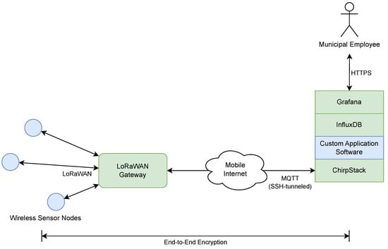
Figure 1.
Block diagram overview of the proposed solution.
This is exemplary of building a specific system using available components and our platform concept as described in [30]. In the following, we detail the two major design aspects.
4.1. Wireless Sensors for Light Intensity Measurements
4.1.1. Sensor Node Hardware and Firmware
As has been discussed in the previous section, the decision was made to use LoRaWAN, operating in the sub-GHz (868 MHz) ISM band, for communications given the operating environment and further considerations.
This directly informed the selection of the basic hardware platform, which became a Nordic Semiconductor nRF52840 (ARM Cortex-M4) SoC, paired with a Semtech LoRa transceiver module (Hoperf RFM95/96/97/98(W) with Semtech SX1276, sourced via SOS electronic GmbH, Hirschau, Germany), based on a hardware survey considering compatibility, availability, and software support. The sensor nodes are class A, the most energy-efficient LoRa device class, with two short receive windows for downlink messages, used for configurability, after uplink transmissions.
For the sensor, a Silicon Labs SI1145 visible light sensor was selected, which is available as an Adafruit SI1145 breakout board that could easily be integrated with the custom base PCB design. The design also reuses additional preexisting custom design artifacts of our platform [30] to raise synergies with other development efforts and projects.
Figure 2 provides a simplified schematic of the sensor nodes’ hardware. The dual-sensor unit includes both parts, with sensors for lamp and ambient light. Single-sensor units do not have a second sensor for ambient light.
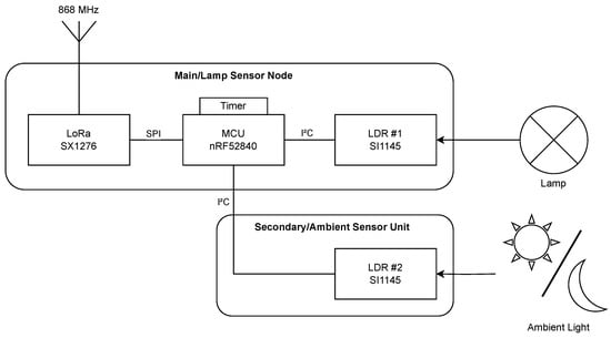
Figure 2.
Simplified schematic of the sensor nodes’ hardware in terms of major components.
As real-time operating system (RTOS) for the software implementation, Zephyr OS [32] was chosen based on prior experiences and previous utilization in our platform [30]. For this, a LoRa driver was available from Semtech Semiconductor, while an additional driver for the light sensor needed to be developed, with a focus on the energy efficiency of the measurements.
Functionally, the node firmware covers the following major aspects:
- •
- Timer-based light intensity measurement with configurable sensor gain and measurement interval as well as autonomous daylight recognition,
- •
- The encoding and transmission of measurement data after measurement,
- •
- The encoding and transmission of status metadata (battery voltage, etc.), and
- •
- The reception and evaluation of configuration (downlink) messages.
As elaborated on before, sensor nodes need day-/nighttime information in order to measure in an energy-efficient manner. To reduce the energy consumption of dual-sensor units, these units always measure the ambient light but do not measure lamp light during the day. Specifically, the firmware as deployed measures and transmits every 30 min during the night to yield ample data for statistical analysis and further evaluations, and every three hours during the day to still have up-to-date status information for the sensors. In suboptimal conditions, messages may fail to reach the server and are not repeated on the application layer.
To provide the sensor nodes with day-/nighttime information, we utilize two light sensors per node in separate housings, allowing for them to be oriented separately from each other as shown in Figure 2 for a dual-sensor unit. One sensor observes the lamp’s light output, and the other serves as an ambient sensor, oriented away from the light source of the lamp. The ambient sensor’s measurement value is compared against a set threshold; if above the threshold (with hysteresis), it is considered day and the daytime regimen applies; otherwise, night.
Figure 3 shows this and that the lamp measurements have strong variation during the night. However, they will always show a distinct gap to the dark reading of the ambient sensor if the lamp is functional. The threshold is configurable and can thus be tuned on a per-lamp basis, enabling adaptation to local conditions.
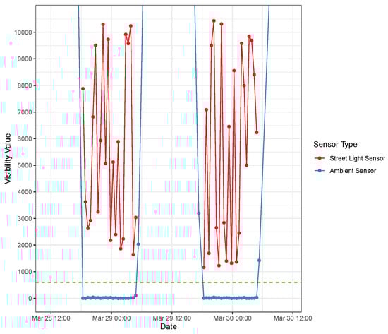
Figure 3.
Example measurement of lamp (red) vs. ambient (blue) light during two subsequent nights. Values on the Y-axis are (unit-less) raw analog-digital converter (ADC) measurement values of the light sensor. This also shows how measured intensities can fluctuate even for the same lamp during one night. The green dashed line shows the selected threshold value.
Figure 4 shows how the measurement of the lamp sensor drops to the range of the ambient sensor when a lamp has failed and how this changes after the lamp’s bulb has been replaced.
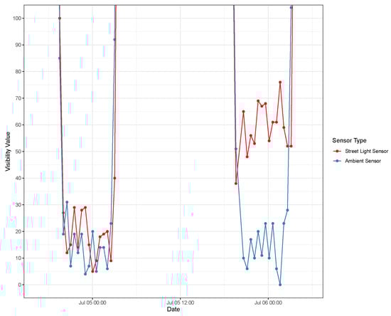
Figure 4.
Example of measurement values of a failed lamp and after its bulb has been replaced. Values on the Y-axis are (unit-less) raw ADC measurement values of the light sensor. This also shows how the lamp sensor’s measurement values drop to the range of the ambient light when the lamp has failed. Also evident is that the replacement is rather dim but still distinguishable from the ambient level by a threshold.
Figure 5 shows changes in nighttime duration throughout the year as evidenced by ambient light measurement values.
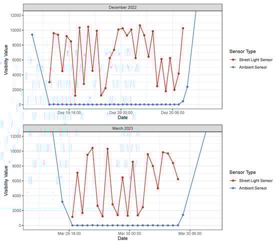
Figure 5.
Changes in nighttime duration throughout the year as evident from ambient light measurement values. The top diagram shows a period in December, the bottom one, one in March. Values on the Y-axis are (unit-less) raw ADC measurement values of the light sensor.
As an alternative to this dual-sensor unit, we also realized a second option in which a sensor node without an ambient light sensor is supplied with nighttime information from the server side. More specifically, the server performs the required calculations, taking into account geographic coordinates of the deployment’s approximate center, and supplies the nodes with the time offset in seconds until the next nighttime start/end when a message is received from a node. With the nodes operating as class A LoRa devices, there are two short windows after each uplink message sent by a node, during which it is ready to receive a downlink message. In contrast to the two-sensor option, this option introduces a dependency on the server side and requires bidirectional communications. It does, however, not require strict time synchronization of the nodes. We still opt for ambient sensors because they provide additional information about external light in the vicinity that could cause unexpected lamp behaviour. In the case of the single-sensor unit, this is achieved by assigning a dedicated nearby ambient sensor on the server side.
Figure 6 summarizes the two different measurement regimens visually.
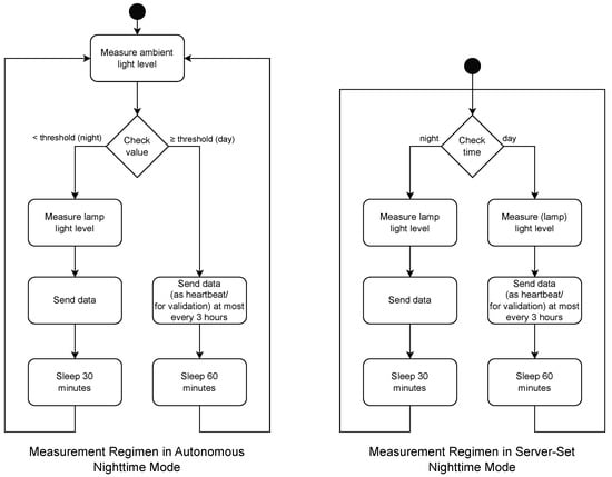
Figure 6.
Light-level measurement regimens of the sensor nodes. Left: measurement regimen of dual-sensor units (with autonomous nighttime detection); right: measurement regimen of single-sensor units (with nighttime information received periodically from the server).
Message payloads utilize a simple custom space-efficient binary encoding.
We created a number of assembly variants to account for different scenarios in the deployment. In addition to the general setup as dual-sensor unit (cf. Figure 7) or single-sensor unit (cf. Figure 8), we varied the orientation of the light sensor as follows:
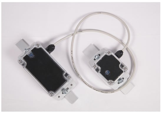
Figure 7.
Hardware of the dual-sensor unit (with metal strips for attachment via cable ties).
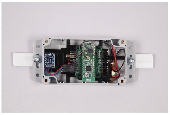
Figure 8.
Hardware of the single-sensor unit (top cover removed to show the internals).
- •
- Sensor node with light sensor oriented straight upwards for lamp types with light source straight above; and
- •
- Sensor node with light sensor oriented upwards at a 45° angle for lamp types with light sources offset via a boom fixture.
Each of the variants has a dedicated firmware image, built from configurable source code to account for these options. In messages, the different assembly variants identify themselves as different types.
Early prototypes of sensor nodes were tested on a selection of lampposts in the main city area of Ilmenau, closer to the company and easier to access in the event of necessary firmware updates. With these, initial measurements were recorded and algorithms tested and validated.
4.1.2. Energy Consumption
Energy consumption was evaluated at various steps along the design process and validated again with the final hardware. For this, we performed current measurements for different states of operation:
- •
- Deep sleep, the dominant state in that the node spends by far most of the time in it—this averaged approximately 21 ;
- •
- Light measurement, including sensor initialization and read-out—this yielded a maximum of for a 125 measurement cycle of a single light sensor; and
- •
- LoRa frame transmission, most critical due to the highest consumption—yielding approximately 120 for transmitting a single measurement data message.
Regarding frame transmissions, there is a trade-off between data rate (DR) and achievable transmission range, which is sensible to make runtime-configurable. For example, the lowest data rate, DR1, takes approximately 830 per message with 16 bytes of payload; DR5 takes approximately 74 , meaning that the transmission time, and hence the energy consumption differs between the two rates by a factor of approximately 11. Therefore, it is beneficial to evaluate if DR5 can be used for most of the nodes.
Regardless of technological specifics, a general major means of conserving energy consists in sending as few messages as possible. In the scope of our work, with an initial solution to be tested, we still opted for more frequent messages than strictly necessary to provide us with more measurement data and additional status information. Based on the measurements, ignoring effects such as batteries’ self-discharge and the influence of temperature fluctuations (day/night, summer/winter) on battery life, we calculated a theoretical lifetime of several years when using DR5.
4.2. Central Components and Software
4.2.1. LoRaWAN Server-Side Software Stack Instance
We set up a ChirpStack instance (in a Docker Compose virtualization context) in an on-premise environment. ChirpStack [28] is an open-source LoRaWAN software stack consisting of several software components. Gateways in the field are integrated via a so-called Gateway Bridge component that communicates with the other components of the stack via Message Queuing Telemetry Transport (MQTT), a broker-based message passing protocol frequently used in IoT contexts. Towards the user, the stack provides a web-based graphical user interface (GUI) for administration purposes and an application programming interface (API; based on gRPC Remote Procedure Calls). Custom or third-party applications dealing with message payloads can be incorporated as so-called integrations via a variety of protocols.
In our case, the network port of the MQTT broker that is part of the compose and required by the ChirpStack instance is forwarded via Secure Shell (SSH) to the gateway in the field, alleviating the need to make the ChirpStack’s MQTT broker publicly available on the internet (a tunneling connection is established from the gateway to the server utilizing an SSH key provisioned with the gateway, and connections to the ChirpStack’s MQTT broker are relayed through this tunnel. We chose this in our setup over opening the server’s MQTT broker (via MQTT Secure (MQTT)) towards the internet because we use an SSH tunnel for remote maintenance regardless, simplifying the setup). The ChirpStack itself requires no specific adaptation beyond configuration. Configuration involves creating logical gateway, application, and sensor instances in the stack via its web GUI or API. In the case of the sensor nodes, node-specific IDs and keys need to be assigned in order for them to be able to communicate.
4.2.2. Gateway
LoRaWAN sensor nodes require a gateway to talk to. Lacking TTN coverage in the target municipal district of the pilot installation, we set up a WisGate Developer D4 RAK7244C LoRaWAN gateway, based on a Raspberry Pi (ARM), Linux, and the relevant portions of the ChirpStack open-source LoRaWAN stack. The gateway requires a permanent power supply and maintains its uplink via an integrated modem (Long-Term Evolution, LTE).
The gateway runs the ChirpStack Gateway Bridge component, configured to talk to higher layers of a ChirpStack instance on our servers via MQTT. For larger deployments (in terms of area), multiple gateways should be deployed, in order to enhance coverage but also reduce the nodes’ energy consumption with higher DR settings becoming possible. The then-necessary deduplication of packets received from multiple gateways happens at the higher layers of the stack.
4.2.3. Custom Server-Side Software
To handle uplink messages from the nodes, perform defect evaluation, and configure nodes, we created two small additional software components running alongside the ChirpStack instance, both implemented in Go.
One, called chirp-feed, interfaces with the ChirpStack as an HTTP integration as well as via its APIs and performs the following tasks:
- •
- Receive incoming (uplink) messages from sensor nodes;
- •
- Decode the messages, then:
- –
- Create and send appropriate replies (configuration instructions: nighttime (dynamic), data rate, and sensor gain (static)) and
- –
- Store data in an InfluxDB [33] time series database instance.
For the nighttime configuration of single-sensor units, we send a downlink message after receiving a message from a node containing the duration until the next dawn and dusk in seconds. This enables a node to time its measurements based on that information and its internal non-global clock. The time information does not need to be highly precise and can ignore variable message flight times.
All configuration parameters can be configured via a Yet Another Markup Language (YAML) configuration file for groups of sensors via a templating mechanism, as well as for individual sensors.
The second piece of custom software, called thurai-influx-processing (thurAI being the name of the project in which the work was carried out), runs daily and processes the data received for the previous night. Based on this, it:
- •
- Determines lamp defects (dead lamps) by comparing measured light intensities from the lamp to corresponding ambient measurement values (for lamps/sensors that have no ambient sensor of their own, another ambient sensor can be assigned configuratively)—in doing so,
- –
- The average of several values around the middle of the night is considered and
- –
- Lamps are only considered defective if the ratio between lamp and ambient light is below a certain (configurable) value for three or more consecutive nights;
- •
- Determines abnormal sensor status (no data, low battery); and
- •
- Generates the processing results as additional data into the InfluxDB.
4.2.4. User Interface
As the interface to the end user, we use a Grafana [34] instance, also running on our local server. Grafana visualizes the data from the database:
- •
- On an end user dashboard, showing:
- –
- Current lamp status (generated data) on a map (Figure 9),
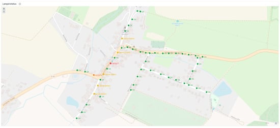 Figure 9. Grafana dashboard showing lamp status on a map of the district of Jesuborn, Ilmenau, Germany. Here, one lamp (red) is correctly showing as defective, one is marked as suspect (orange) because its light intensities were lower than they should be for the last night, and several more show a temporary lack of data due to difficult radio conditions at their specific locations.
 - –
- A list of sensor identifiers and location descriptions, and
- –
- Lamp status over time (Figure 10);
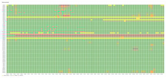 Figure 10. Grafana dashboard showing the status of all sensors in the pilot installation over time (here, over the course of 90 days). Status colors correspond with the explanations for Figure 9.
- •
- On an internal dashboard, showing current sensor status and sensor status over time (last message, messages received, battery); and
- •
- Optionally notifying select users about defects and data anomalies via its alerting mechanisms.
5. Field Trial
The developed solution was validated via a pilot installation in the district of Jesuborn of the muncipality of Ilmenau, Thuringia, Germany. This district has between 50 and 60 lampposts, 52 of which were eventually outfitted with sensor nodes. We deployed the gateway at an elevated location in a hiking cottage on a small hill overlooking Jesuborn and thus providing good LoRaWAN coverage for the whole district. The deployment of the sensor nodes was carried out from July 2023. Figure 11 shows two examples of lampposts in the deployment outfitted with sensor nodes. The examples also show the utilization of a dual-sensor unit with an angled lamp light sensor unit on the lamp with a boom fixture (where the ambient sensor can be oriented away from the lamp’s beam), and the use of a single-sensor unit with a straight-up lamp light sensor in the other case.
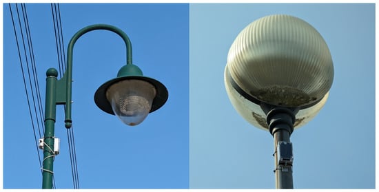
Figure 11.
Two types of lamps in the deployment, outfitted with our sensors. These are also exemplary for two major types of designs: light source centered on the pole and offset via a boom fixture.
Most of the sensor nodes deployed are dual-sensor units with a light sensor looking either straight up (bulb-on-top-type posts) or up at an angle (bulb on boom/fixture) with an ambient light sensor facing away from the lamppost’s light source. These units determine nighttime based on ambient light readings. Units without a local ambient sensor were deployed in cases where local conditions contradicted a localized ambient light measurement. Cases requiring these are typically lampposts in the immediate vicinity of windows, (reflecting) walls, or other light sources. In addition, we deployed a single-sensor unit as a stand-alone ambient light reference source in a dark location: a lamppost at the end of a road without any nearby buildings or infrastructure. The association of separate ambient light sensors with single-sensor units is only carried out on the server side, in the course of defect evaluation, and configured there.
The majority of the sensors utilize LoRa data rate DR5 to reduce the active radio time as much as possible and thus save energy, as discussed in the previous section. In some problematic spots, a lower data rate promising higher range and penetration was configured. To determine the best DR setting, we performed test measurements in advance as the data rate is hard-coded in the sensors’ firmware implementation. We decided not to change the data rate via remote configuration without prior testing, to avoid potentially effecting a complete communication loss. Alternatively, one could evaluate the use of an autonomous data rate adaptation mechanism within the nodes’ firmware.
At the time of this writing, the deployment has been in operation for nine months, spanning from summer through winter, with the resulting shifts in nighttime start, end, and duration, and all kinds of weather. The following list briefly enumerates some experiences and observations:
- •
- During this time, even though no lamps happened to fail on their own, one lamppost was toppled in a traffic accident, causing it to fail. The failure was promptly and correctly identified by the server-side processing and visualized accordingly (see Figure 9, still defective).
- •
- For some lamps, the ability to retroactively adjust the required threshold between light from the lamp and ambient light was used to account for very dim lamps. This shows another benefit of the system as those bulbs, however, should probably be rather replaced anyway.
- •
- Despite having taken care in selecting data rates for expectedly difficult locations, there are range issues at some locations, mainly due to more obstacles (buildings) in the line of sight to the gateway. There, we observe a certain prevalence of gaps in data, or no data at all. As changing the data rate requires taking them off the posts, re-flashing the devices, and re-placing them after the operation, this has so far not been carried out. Here, an option to enhance the system via an over-the-air firmware update mechanism or adding data rate settings to the configuration options could enhance the system’s overall flexibility.
- •
- During the wintertime, there was snow for a number of days in a row, evidently also on the sensors, resulting in some erroneous failure detections. This could be improved by mounting all nodes at an angle to allow snow to slide off immediately.
- •
- The configurability of nodes in the field, as well as the option to adjust server-side processing retroactively, proved good to have.
- •
- Grafana was found to be well-suited for visualizing the lamp status for end users and to alert via notifications.
6. Discussion
Overall, the trial showed that our system is able to handle a variety of lamps with differences in lighting technology and lamp design. It is independent of the actual lamp and can thus be employed with any lamp. The configuration options are essential for a retrofit systems as they allow tuning the system to given local conditions. Our differential measurement of the light using a separate lamp and an ambient light sensors helps in handling daylight changes throughout the year. In addition, this system enables the monitoring of lamp status and possible degradation in brightness over time. This is indicated by observed values before and after a change of the light bulbs. However, as these changes involve the replacement with newer, potentially brighter bulbs, only long-term observations will yield insights into the bulbs’ life cycles. Collected data can then be used for predictive maintenance, proactively scheduling lamp replacements. We assume that the intensity of light emitted degrades over the lifetime of a light source, but the time span of the operation of the pilot installation is, at the time of this writing, too short for definitive conclusions in this regard. Keeping the deployment running will hopefully provide a wealth of information for this. Complicating this are the facts that measurements are not taken where the beam is strongest, that the light emitted by the lamp’s bulb is not measurable in isolation, and that weather (esp., fog) and dirt on the sensor housing and bulb enclosure influence the amount of light from the lamp reaching the sensor.
During the trial, an additional type of defect where lamps show a flickering behavior has come to our attention. Lamps may start flickering as they age, with different characteristics depending on the type of bulb. According to administrative staff, another possibility is the presence of too much ambient light irritating the control logic, if any, of the lamp (twilight sensor). It should be possible to implement an additional flicker detection measurement regimen that could address this. Doing so will require some additional form of adaptivity, either automatic or via configuration from the server side, to account for the different flicker frequencies of different lamp types.
With today’s system, it is, however, possible to exactly locate defective lamps and thus save efforts in locating a reported defective lamp. Normally, maintenance staff would turn on an entire line of lamps (during the day, with lamps not being switchable individually) and then locate the defective lamp manually. With our system, the defective one can be pinpointed without toggling the line at all. In addition, problems with dim lamps can also be reported to the administration to facilitate required changes before the lamp fails completely. This contributes to public safety as the foremost function of lamps is to provide sufficient brightness (as shown in [1]). At the same type, if traditional bulbs are replaced with more energy-efficient (or even LED) bulbs when they fail, operational energy costs can successively be reduced.
Based on this assessment, our system fulfills our goals and helps in monitoring the lamp status anywhere, provided that a suitable LoRaWAN gateway can be deployed to cover the areas of interest (or public TTN coverage is available).
The cost of the developed solution of approximately 120 EUR for the hardware components of a single sensor in small-scale production exceeds what municipalities would be willing or able to pay for such a system. Costs could be reduced in several ways:
- •
- Consider designing and manufacturing a single hardware variant. This would be a sensor node with sensors in both orientations (configurable utilization) that can also function as an ambient sensor.
- •
- Evaluate, based on the data obtained from the field trial, whether it would be sufficient to have only one or very few dedicated ambient light sensors in select spots around town and use these to determine the general ambient light level from which day- and nighttimes are determined and against which the light output of lamps measured by the sensor nodes is compared. In contrast to the current per-node pairing, this will dispense with a localized ambient light level.
- •
- Also based on the data, evaluate whether ambient light sensors are necessary at all; just consider light emission values by themselves and provide nighttime information from the server side in all cases.
Battery operation implies necessary maintenance whenever the batteries run out. With the current solution, we expect a battery lifetime of at least two years in practice, with theoretical expectations based on current measurements for different states of operation promising even more years. Regardless of the exact lifetime, batteries will run out eventually, and swapping them when this results in immediate costs (for new batteries) and secondary ones (lifting platform, staff) as well as the risk of damage to the sensors in the course of the procedure. This could be addressed by adding a small solar panel to the sensor nodes and using rechargeable batteries that recharge during the day. Our experience makes it seem unlikely that nighttime illumination from the lamp itself will contribute much in this regard. This, of course, increases the costs per sensor and potentially requires a different mounting solution as this results in a greater susceptibility to wind and additional considerations in the exact placement of the sensor so that the panel is oriented towards the south and neither obstructs the light beam too much nor the actual sensor. Of course, reliance on solar power may lead to issues in winter when the sun rises lower in the sky and snow may accumulate on the panel.
While we encountered some range issues in the field trial, this should not be an issue in areas with good TTN LoRaWAN coverage, especially if coverage by multiple gateways overlaps. Alternatively, range issues can be addressed by deploying multiple gateways, e.g., at opposite ends of an elongated deployment area. It would also be interesting to evaluate the mesh networking (multi-hop) capabilities that have been added to LoRaWAN in the meantime.
With the experiences and algorithmic adjustments made in the course of the field trial, it might be considered to move logic from the server/edge into the nodes. A benefit of doing so would be that evaluation results (binary assessment?) are more compact than raw measurement values, thus shortening messages and prolonging lifetimes, assuming that the local processing consumes less. Currently, we also take more measurements than strictly necessary (but opted to do so to gather more data). Even adaptive flicker detection, if realized, could be carried out on the sensors, possibly even if AI algorithms are employed [35,36].
Even though there were none such in our field trial, there may be lamps in practice that are only lit for part of the night. Handling these would require specific measures, e.g., in the selection of the times at which measurements are performed or analyzed on the server-side. The system is capable of handling these aspects.
In our field trial, we had to adjust the lamp vs. ambient light detection threshold retroactively for particularly dim lamps. It should be possible to implement an auto-tuning algorithm to set these parameters automatically based on several nights’ past observations.
7. Conclusions and Outlook
This paper describes the design and implementation of an adaptive, retrofittable lamp status monitoring system, as well as conclusions from a subsequent field trial via a comprehensive pilot installation. The principal function has been validated via the field trial that is still being continued. The functionality currently is limited to failure detection, i.e., a lamp being off when it should be on. Even so, the system fulfills our goal to provide a non-invasive retrofitting solution that does not require an integration with the lamp’s wiring or lampposts and uses differential optical monitoring (lamp vs. ambient light) to add dynamic day length handling. Using LoRaWAN and tuning the data rate settings, we ensure an energy-efficient operation of the sensor nodes.
In the future, we plan to extend our field trial to collect long term data and verify whether the system is capable of providing data for predictive maintenance applications related to smart lighting. In addition, we want to tackle the mentioned enhancements in the system design. The main goals here are better energy efficiency as well as adding the detection of further types of defects, such as flickering, as this can be very annoying to citizens.
Author Contributions
Conceptualization, S.S., S.K. and M.G.; methodology, S.S. and S.K.; software, S.S., S.K. and M.G.; validation, S.S., S.K. and M.G.; formal analysis, S.S., S.K. and M.G.; investigation, S.S., S.K. and M.G.; resources, T.H.; data curation, S.S.; writing—original draft preparation, S.S., S.K. and M.G.; writing—review and editing, S.S., S.K., M.G. and T.H.; visualization, S.S. and M.G.; supervision, T.H.; project administration, S.K. and M.G.; and funding acquisition, T.H. All authors have read and agreed to the published version of the manuscript.
Funding
This work is part of the thurAI research project which is funded by the German State of Thuringia via the Thüringer Aufbaubank under the reference 2021 FGI 0008.
Institutional Review Board Statement
Not applicable.
Informed Consent Statement
Not applicable.
Data Availability Statement
The data presented in this study are available on request from the corresponding author. The data are not publicly available due to privacy.
Conflicts of Interest
The authors declare no conflicts of interest.
References
- Beccali, M.; Bonomolo, M.; Leccese, F.; Lista, D.; Salvadori, G. On the impact of safety requirements, energy prices and investment costs in street lighting refurbishment design. Energy 2018, 165, 739–759. [Google Scholar] [CrossRef]
- Landertshamer, O.; Benseny, J.; Hämmäinen, H.; Wainio, P. Cost model for a 5G smart light pole network. In Proceedings of the 2019 CTTE-FITCE: Smart Cities & Information and Communication Technology (CTTE-FITCE), Ghent, Belgium, 25–27 September 2019; pp. 1–6. [Google Scholar]
- Agramelal, F.; Sadik, M.; Moubarak, Y.; Abouzahir, S. Smart Street Light Control: A Review on Methods, Innovations, and Extended Applications. Energies 2023, 16, 7415. [Google Scholar] [CrossRef]
- A CIO’s Guide to Smart Street Lighting-Enabled Smart City Networks. Available online: https://tondo-iot.com/white-papers/a-cio-guide-to-smart-street-lighting-enabled-smart-city-network/ (accessed on 13 March 2024).
- Bingöl, E.; Kuzlu, M.; Pipattanasompom, M. A LoRa-based Smart Streetlighting System for Smart Cities. In Proceedings of the 2019 7th International Istanbul Smart Grids and Cities Congress and Fair (ICSG), Istanbul, Turkey, 25–26 April 2019; pp. 66–70. [Google Scholar] [CrossRef]
- Tang, D.; Ding, F.; Deng, B.; Zhang, P.; Wang, Q.; Lv, H. An Intelligent Fault Diagnosis Method for Street Lamps. In Proceedings of the 2021 International Conference on Internet, Education and Information Technology (IEIT), Suzhou, China, 16–18 April 2021; pp. 300–303. [Google Scholar] [CrossRef]
- Lee, J.R.; Hsueh, S.L. Construct Automatic Monitoring System for Residential District Street Lamps to Increase Maintenance Efficiency. Appl. Mech. Mater. 2012, 182, 1402–1407. [Google Scholar] [CrossRef]
- Lartsey, P.E.; Ayitey, D.T.; Acakpovi, A.; Arthur, R.E. IoT Based Street Light Controller and Monitoring System. In Proceedings of the 2021 IEEE 8th International Conference on Adaptive Science and Technology (ICAST), Accra, Ghana, 25–26 November 2021; pp. 1–7. [Google Scholar] [CrossRef]
- Sánchez Sutil, F.; Cano-Ortega, A. Smart Public Lighting Control and Measurement System Using LoRa Network. Electronics 2020, 9, 124. [Google Scholar] [CrossRef]
- Vieira, T.; Brito, D.; Ribeiro, M.; Araujo, I. An IoT Based Smart Utility Pole and Street Lighting System. In Proceedings of the IEEE Chilean Conference on Electrical, Electronics Engineering, Information and Communication Technologies (CHILECON), Valparaiso, Chile, 13–27 November 2019; pp. 1–5. [Google Scholar] [CrossRef]
- Devi, P.K.; Arulanantham, D.; Kalaivanan, C.; Gomathi, N.; Arunkumar, J.; Ramkumar, G. An Secure and Low Energy Consumption based Intelligent Street Light Managing System using LoRa Network. In Proceedings of the 2022 6th International Conference on Electronics, Communication and Aerospace Technology, Coimbatore, India, 1–3 December 2022; pp. 638–645. [Google Scholar] [CrossRef]
- Ye, J. Design and practice of an intelligent street lamp based on edge computing. In Proceedings of the 2021 International Conference on Intelligent Transportation, Big Data & Smart City (ICITBS), Xi’an, China, 27–28 March 2021; pp. 83–85. [Google Scholar] [CrossRef]
- Tung, N.T.; Phuong, L.M.; Huy, N.M.; Hoai Phong, N.; Dinh Huy, T.L.; Dinh Tuyen, N. Development and Implementation of Smart Street Lighting System based on Lora Technology. In Proceedings of the 2019 International Symposium on Electrical and Electronics Engineering (ISEE), Ho Chi Minh City, Vietnam, 10–12 October 2019; pp. 328–333. [Google Scholar] [CrossRef]
- Jia, G.; Han, G.; Li, A.; Du, J. SSL: Smart Street Lamp Based on Fog Computing for Smarter Cities. IEEE Trans. Ind. Informatics 2018, 14, 4995–5004. [Google Scholar] [CrossRef]
- Pasolini, G.; Buratti, C.; Feltrin, L.; Zabini, F.; De Castro, C.; Verdone, R.; Andrisano, O. Smart City Pilot Projects Using LoRa and IEEE802.15.4 Technologies. Sensors 2018, 18, 1118. [Google Scholar] [CrossRef] [PubMed]
- Lian, L.S.; Darsono, A.M. Smart Street Light with LoRa Technology. In Proceedings of the Innovation and Technology Competition (INOTEK) 2021, Melaka, Malaysia, 2–9 June 2021; pp. 67–68. [Google Scholar]
- Tian, Y.; Wang, Y. Street Lamp Intelligent Monitoring System Design Based on NB-IoT Technology. J. Phys. Conf. Ser. 2020, 1617, 012003. [Google Scholar] [CrossRef]
- Sravani, N.; Latha, Y.; Nirmala, G.; Ijmtst, E. Street Light Controlling and Monitoring of Fault Detection using LoRa. Int. J. Mod. Trends Sci. Technol. 2021, 7, 242–245. [Google Scholar]
- Ai, M.; Wang, P.; Ma, W. Research and application of smart streetlamp based on fuzzy control method. Procedia Comput. Sci. 2021, 183, 341–348. [Google Scholar] [CrossRef]
- WLINK Wireless Street Lamp Monitoring. Available online: https://www.wlink-tech.com/wireless-smart-street-lamp-monitoring_d0054.html (accessed on 13 March 2024).
- Intelligent Streetlamps in Essen. 2020. Available online: https://www.german-energy-solutions.de/GES/Redaktion/EN/News/2020/20200630-intelligent-streetlamps.html (accessed on 13 March 2024).
- Retrofit: Turning Street Light Poles from Energy Consumers to Solar Energy Providers. Available online: https://www.engoplanet.com/single-post/retrofit-turning-street-light-poles-from-energy-consumers-to-solar-energy-providers (accessed on 13 March 2024).
- Street Light Monitoring. Available online: https://appinfoinc.com/solutions/street-light-monitoring/ (accessed on 13 March 2024).
- Raja, R.; Regina, S. Monitoring Street Light Using IoT Technology to Detect Fault Automatically. Gis Sci. J. 2023, 10, 571–581. [Google Scholar]
- Mohite, A.; Sonawne, R.; Arkade, S.; Joshi, S.; Patil, V. IoT based Street Lights for Smart City. Int. J. Sci. Res. Dev. 2017, 5, 1522–1524. [Google Scholar]
- Bonomi, F.; Milito, R.; Zhu, J.; Addepalli, S. LoRa for the Internet of Things. In Proceedings of the International Conference on Embedded Wireless Systems and Networks (EWSN), Graz, Austria, 15–17 February 2016; Volume 103, pp. 1377–1387. [Google Scholar]
- Adelantado, F.; Vilajosana, X.; Tuset-Peiro, P.; Martinez, B.; Melia-Segui, J.; Watteyne, T. Understanding the limits of LoRaWAN. IEEE Commun. Mag. 2017, 55, 34–40. [Google Scholar]
- ChirpStack Documentation. Available online: https://www.chirpstack.io/docs/ (accessed on 13 March 2024).
- LoRaWAN Security: Full End-to-End Encryption for IoT Application Providers. 2020. Available online: https://lora-alliance.org/wp-content/uploads/2020/11/lorawan_security_whitepaper.pdf (accessed on 13 March 2024).
- Krug, S.; Goetze, M.; Schneider, S.; Hutschenreuther, T. A Modular Platform to Build Task-Specific IoT Network Solutions for Agriculture and Forestry. In Proceedings of the International Workshop on Metrology for Agriculture and Forestry (MetroAgriFor), Pisa, Italy, 6–8 November 2023. [Google Scholar]
- Jung, F.; Krug, S. Towards Multi-hop BLE-Based Communication Using a Custom Routing Approach. In Proceedings of the 20th Edition of the Fachgespräch Sensornetze (FGSN 2023), Potsdam, Germany, 4–7 September 2023. [Google Scholar]
- Zephyr OS Documentation. Available online: https://docs.zephyrproject.org/latest/ (accessed on 13 March 2024).
- InfluxDB v1 Documentation. Available online: https://docs.influxdata.com/influxdb/v1/ (accessed on 13 March 2024).
- Grafana Labs: Documentation. Available online: https://grafana.com/docs/ (accessed on 13 March 2024).
- Pandey, R.; Uziel, S.; Hutschenreuther, T.; Krug, S. Weighted Pruning with Filter Search to Deploy DNN Models on Microcontrollers. In Proceedings of the 2023 IEEE 12th International Conference on Intelligent Data Acquisition and Advanced Computing Systems: Technology and Applications (IDAACS), Dortmund, Germany, 7–9 September 2023; Volume 1, pp. 1077–1082. [Google Scholar] [CrossRef]
- Pandey, R.; Uziel, S.; Hutschenreuther, T.; Krug, S. Towards Deploying DNN Models on Edge for Predictive Maintenance Applications. Electronics 2023, 12, 639. [Google Scholar] [CrossRef]
Disclaimer/Publisher’s Note: The statements, opinions and data contained in all publications are solely those of the individual author(s) and contributor(s) and not of MDPI and/or the editor(s). MDPI and/or the editor(s) disclaim responsibility for any injury to people or property resulting from any ideas, methods, instructions or products referred to in the content. |
© 2024 by the authors. Licensee MDPI, Basel, Switzerland. This article is an open access article distributed under the terms and conditions of the Creative Commons Attribution (CC BY) license (https://creativecommons.org/licenses/by/4.0/).