Article

Design Data and Finite Element Analysis of 3D Printed Poly(ε-Caprolactone)-Based Lattice Scaffolds: Influence of Type of Unit Cell, Porosity, and Nozzle Diameter on the Mechanical Behavior

NeMO Lab, ASST Niguarda Cà Granda Hospital, 20162 Milan, Italy
*
Author to whom correspondence should be addressed.
Eng 2022, 3(1), 9-23; https://doi.org/10.3390/eng3010002
Submission received: 29 November 2021 / Revised: 20 December 2021 / Accepted: 22 December 2021 / Published: 25 December 2021
(This article belongs to the Special Issue Advanced Bioengineering Approaches for Biopolymers and Composites)

Abstract

:
Material extrusion additive manufacturing (MEAM) is an advanced manufacturing method that produces parts via layer-wise addition of material. The potential of MEAM to prototype lattice structures is remarkable, but restrictions imposed by manufacturing processes lead to practical limits on the form and dimension of structures that can be produced. For this reason, such structures are mainly manufactured by selective laser melting. Here, the capabilities of fused filament fabrication (FFF) to produce custom-made lattice structures are explored by combining the 3D printing process, including computer-aided design (CAD), with the finite element method (FEM). First, we generated four types of 3D CAD scaffold models with different geometries (reticular, triangular, hexagonal, and wavy microstructures) and tunable unit cell sizes (1–5 mm), and then, we printed them using two nozzle diameters (i.e., 0.4 and 0.8 mm) in order to assess the printability limitation. The mechanical behavior of the above-mentioned lattice scaffolds was studied using FEM, combining compressive modulus (linear and nonlinear) and shear modulus. Using this approach, it was possible to print functional 3D polymer lattice structures with some discrepancies between nozzle diameters, which allowed us to elucidate critical parameters of printing in order to obtain printed that lattices (1) fully comply with FFF guidelines, (2) are capable of bearing different compressive loads, (3) possess tunable porosity, and (3) overcome surface quality and accuracy issues. In addition, these findings allowed us to develop 3D printed wrist brace orthosis made up of lattice structures, minimally invasive (4 mm of thick), lightweight (<20 g), and breathable (porosity >80%), to be used for the rehabilitation of patients with neuromuscular disease, rheumatoid arthritis, and beyond. Altogether, our findings addressed multiple challenges associated with the development of polymeric lattice scaffolds with FFF, offering a new tool for designing specific devices with tunable mechanical behavior and porosity.

1. Introduction

Highly controlled lattice architectures are seeing growing interest in different application fields, ranging from the manufacturing of lightweight orthosis [1,2,3], scaffolds for tissue engineering [4,5,6,7,8,9,10,11], implantable medical devices [12,13,14], stimuli-responsive soft-robotics [15,16,17], and topology optimization for architectural structures [18]. Such lattice structures comprise a base form, namely unit cell, which is spatially repeated across the entire structure either in a fixed x, y, z geometry or with varying degrees of asymmetry [19,20,21,22,23]. From a design perspective, the key advantages of lattice structures include dimensional accuracy, surface quality, residual stresses, and microstructures, dictating not only the mechanical performance of the overall structure but also other critical features such as surface area, porosity, fluidic dynamics, and materials consumption [24,25]. Therefore, control over these design parameters is of fundamental interest for the optimization and prediction of the behavior of these structures for specific applications.
Material extrusion additive manufacturing (MEAM), also known as 3D printing, is an advanced manufacturing method able to produce lattice structures (and beyond) via precise layer-wise addition of material through its extrusion from the millimeter- or micron-scaled nozzle [26]. However, the potential of MEAM to prototype lattice structures is hampered by restrictions imposed by manufacturing processes that lead to practical limits on the form and dimension of structures that can be produced. Indeed, as previously reported by Panetta and co-workers [27], such structures are mainly manufactured by selective laser sintering (SLS) or stereolithography (SLA) [28] since MEAM does not have the adequate resolution to precisely print microstructures. Nevertheless, limitations such as minimum cell size, thickness of walls/edges/faces, cell geometry, nozzle diameter, printing parameters, or porosity have not been fully evaluated. On the other hand, as highlighted by Silva et al., [28], albeit MEAM could seem inadequate compared to SLS and SLA for the production of lattice structures, it allows to use biocompatible and bioabsorbable polymers more suitable for biomedical applications, the feedstock is safer and easier to handle and does not require additional post-processing.
For these reasons, in this study, we aimed to investigate the capability of MEAM to produce custom-made lattice structures, combining fused filament fabrication (FFF), including computer-aided design (CAD), with the finite element method (FEM) to assess their printability, tune the porosity, and predict their mechanical behaviors, useful for tissue engineering and biomedical implants.
We focused our attention on generating and examining four types of 3D CAD scaffold models with different geometries (reticular, triangular, hexagonal, and wavy) as the unit cells. In addition, paying attention to the available polymers for 3D printing purposes, we used poly(ε-caprolactone) (PCL) because of its low melting point of 60 °C, high printability, soft-like properties, biocompatibility, and ease of multi-functionalizations with bioactive cues (i.e., biomolecules, proteins/peptides, growth factors, and nano-composites) [29].
Each PCL-based lattice structure was 3D printed with different unit cells (ranging from 1 to 5 mm) using two nozzle diameters (i.e., 0.4 and 0.8 mm) in order to assess the printability limitation and the scaffolds manufacturability in terms of minimum unit cell size, and pore size compared to the nozzle diameter. Further, the mechanical behavior of such lattice scaffolds was studied using FEM, combining compressive modulus and shear modulus either in linear or nonlinear hyperelastic models. The CAD-based FEM method allowed us to predict and understand the mechanical properties of the engineered scaffolds vs. the nozzle diameter, thus providing tools for the design and control of the geometric configuration of the lattice structures.
Ultimately, this study aims to address the design complexity issues for lattice structures creation by MEAM, realizing a CAD/FEM-driven methodology that could be a useful tool for designers, materials scientists, and MEAM engineers who wish to apply complex structures for advanced designs, where the techniques described could be readily applied for specific applications, such as light-weighting orthosis, scaffolds for targeted tissues or 3D cell cultures, controlled drug-release, medical devices, and soft robotics.
We hypothesize that the controlled biomechanics and porosity of lattice scaffolds fabricated by 3D printing could be a useful tool obtained through designing different inner geometries via the FEM method.

2. Materials and Methods

2.1. Materials

Poly-ε-Caprolactone (PCL) (Filoalfa, Ozzero, Italy) was used as polymer filament without further modifications. All materials were handled with gloved hands and following standard surface analysis laboratory practices to minimize any possible contamination.

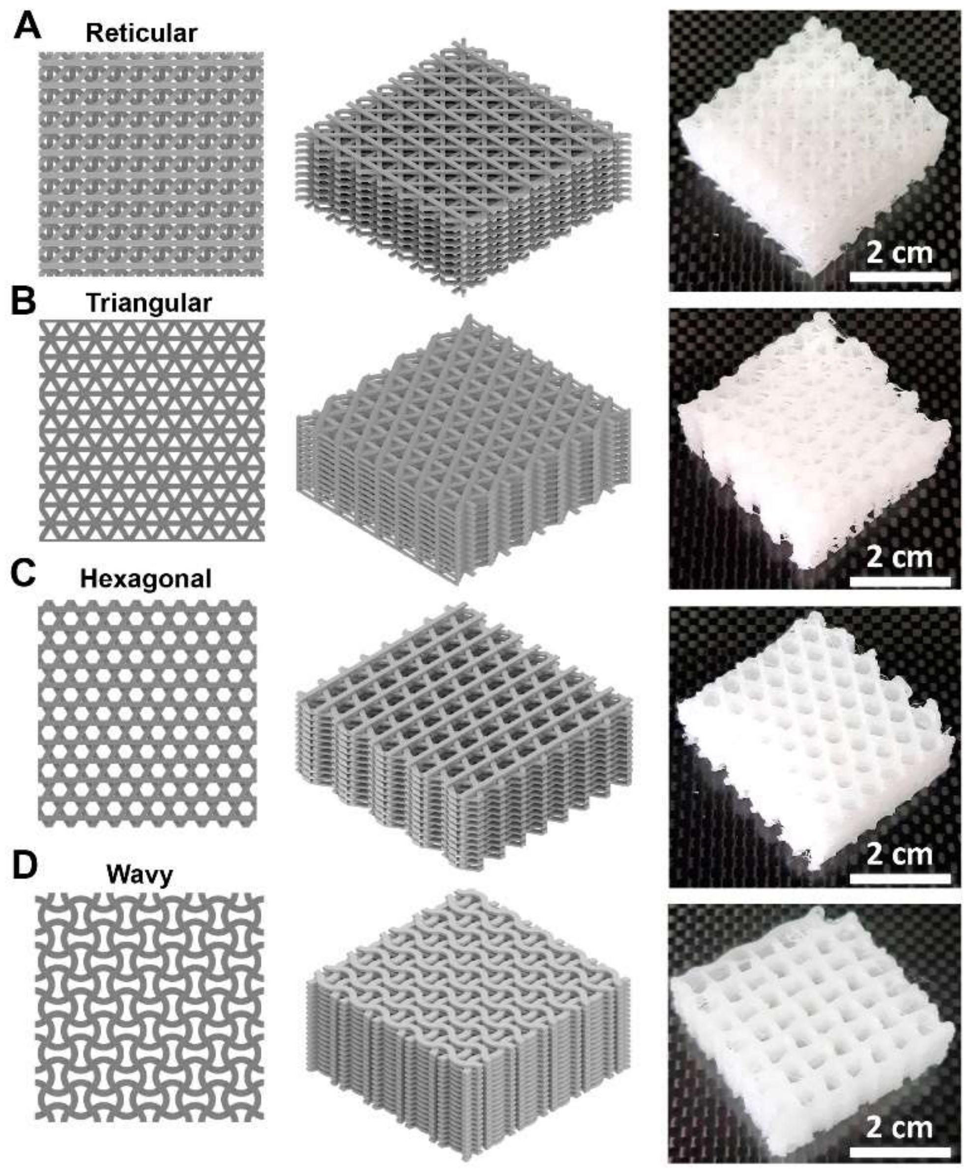
2.2. CAD-Based Lattice Structures Design

Four different lattice structures CAD designs were created using Autodesk Inventor® (Autodesk 2020, McInnis Parkway San Rafael, CA, USA), simulating the superimposition of different paths during the 3D printing procedure. The reticular, triangular, hexagonal, and wavy geometries were designed making the angle between different paths variables. In order to create the structures to be tested, each pattern was considered as a linear repetition of a unit cell size; five cell sizes were designed and tested (ranging from 1 to 5 mm). All designed scaffolds featured 5 × 5 cell units in the x and y directions, with 15 layers of thickness for triangular and hexagonal geometries and 16 layers of thickness for reticular and wavy ones. The porosity of the CAD models was obtained by measuring the occupied volume of each scaffold, and the designed porosity (PCAD) was calculated as follows (Equation (1)):
P CAD   =   ( 1 V f V t o t )   ×   100
in which Vf is the occupied volume of the scaffold, and Vtot is the bulk volume of the CAD model.

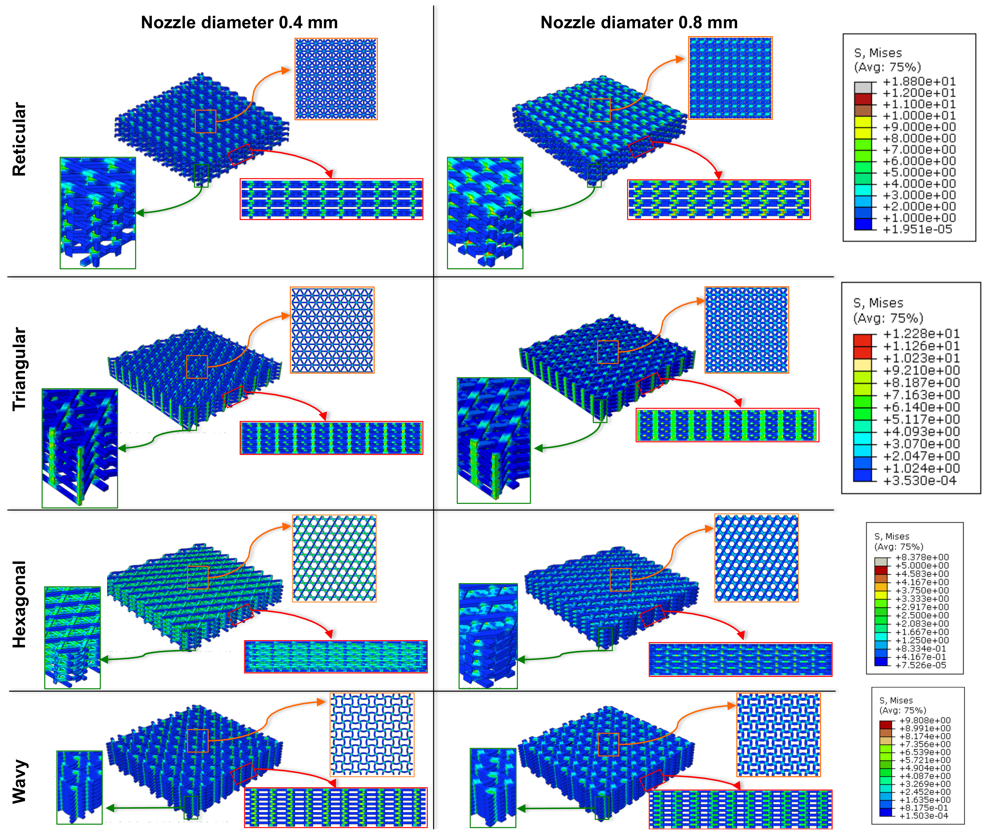
2.3. Finite Element Method (FEM) Modeling

In order to predict the mechanical behavior of designed lattice scaffolds and to assess the dependency of the mechanical properties with respect to the printing path width, the compressive and shear moduli were simulated by finite element analysis using ABAQUS/standard® (Dassault Systemes Simulia Corporation., Johnston, RI, USA). Each CAD model was imported into the FE software as a continuous unique part. The PCL-based scaffolds properties were simulated by both linear and nonlinear elastic behavior. In the linear elastic condition, the elastic modulus and Poisson’s ratio of PCL were assumed to be 350 MPa and 0.3, respectively, as reported previously [30,31]. The elastic modulus was then used in the FE simulation with the assumption of linear elastic deformation and considering the PCL material as isotropic. In the STEP section of the model, the Nlgeom option was set to on in order to allow results with nonlinear behavior. An automatic incrementation was selected for the simulation, with a maximum number of increments equal to 100 and an increment size increasing from an initial size of 0.01 up to 0.1 to speed up the process. No particular problems in the iterations were registered. The minimum increment size was left to a default 1.0 × 10⁻⁵ value. The output requested from the simulations contains stresses, strains, displacement, and Force/Reaction to allow us to calculate the related compressive modulus. These variables were calculated every n number of increments. Then, compression simulation was performed on the CAD models constraining the lower face of the scaffold, denying any possible movement or rotation with respect to the reference system, and 1.5% compressive strain was exerted to the top of the model. The compressive elastic modulus of each scaffold was obtained from Equation (2):
E comp = ( σ c o m p ε )
in which σcomp is the equivalent maximum stress reached for the imposed displacement, and ε is the imposed strain. Since:
σ comp = ( R A e q )  
where R is the reaction force of the constrained lower side of the scaffold, and Aeq is the resistant equivalent area of the scaffold (see Figure S1 for further details). The imposed strain was calculated from Equation (4) as follows:
ε = ( δ t )
where δ is the imposed displacement, and t is the thickness of the scaffold (see Figure S1 for further details). Hence, the final formulation of the compressive elastic modulus, taking into account all the boundary conditions already mentioned, is:
E comp = (   R A e q δ t )
Afterward, shear moduli of scaffolds with four types of microstructures were estimated. The directions of the scaffold’s length were called x-direction, while the in-plane orthogonal direction was called y-direction. A displacement parallel to the x- and y-direction was imposed to the upper surface of each scaffold, and the linear shear modulus was then calculated with Equation (6):
G zx = (   τ z x γ x ) G zy = (   τ z y γ y )
where τ is the shear stress of the homogenized lattice structure for the maximum imposed displacement, and γ is the shear strain of the simulation. The shear stress can be then obtained using:
τ zx = (   R x A e q ) τ zy = (   R y A e q )
where Rx and Ry are the reaction forces in the x- and y-direction of the constrained portion of the tested scaffold, while Aeq is the resistant equivalent area of the scaffold. The shear strain instead is calculated as follows:
γ = (   δ t )
where δ is the applied displacement of the upper part of the scaffold and t is the total thickness of the scaffold as calculated before. Hence, by combining the previous equations, it is possible to obtain the final shear modulus formulation (Equation (9)):
G zx = (   R x A e q   δ x t ) G zy = (   R y A e q   δ y t )
For nonlinear elastic behavior, the compressive mechanical behavior of each scaffold was predicted by using the nonlinear hyperelastic van der Waals material model [31,32]. For this model, the strain energy function is:
U = μ   λ m 2 3 ln 1     η + η 2 3   α   Ι ¯ 3 2 3 2   + 1 D   J e l 1 2 2 l n J e l Ι ¯ = 1 β Ι ¯ 1 + β Ι ¯ 2   and   η = Ι ¯ 3 λ m   2 3
where U is the strain energy potential, Jel is the elastic volume ratio, I1 and I2 are the first and second invariants of the deviatoric strain, μ, λm, α, and β describe the deviatoric behavior of the material, and D introduces the compressibility [33].
Since in van der Waals hyperelastic material model, μ0 (initial shear modulus) is equal to μ (shear behavior of the material in van der Waals), D value can be calculated as follow:
D =   3 1 2 υ μ   1 + υ
The utilized parameters for the van der Waals hyperelastic model for describing the nonlinear mechanical behavior of PCL were μ = 140, λm = 1.9, α = 6, β = 0, and D = 0.00659, as reported previously [31].

2.4. Fused Deposition (FDM) Printing

All lattice structures were 3D printed using fused deposition modeling (FDM) technology through QXXL Full-Metal (Sharebot, Nibionno, Italy). PCL filaments (1.75 mm diameter) were extruded through a 0.4 mm and 0.8 mm diameter nozzle at the temperature of 130 °C. The bed temperature was set at 40 °C. The layer height was 0.4 mm, and the nozzle travel rate was 3600 mm min−1. Each object was modeled using Autodesk Inventor® software, then exported in stereolithography (.stl) format and sliced using Simplify3D® software to be printed. To ensure the adhesion of the scaffolds to the surface of the printing platform, a 3D glue stick (Magigoo™, Swieqi, Malta) was used.

2.5. Spectroscopic Characterizations of 3D Printed Lattice Structures

Raman analysis was conducted using Progeny™ spectrometer (Rigaku Corporation, Tokio, Japan) with a 1064 nm laser source and selectable laser output set at 490 mW. The spectral range is 200–2500 cm−1 with transmission-type volume phase grating. The spectral resolution is 15–18 cm−1, and the detector is a thermoelectrically cooled indium gallium arsenide (InGaAs) [34]. The samples were analyzed with 60 cumulative scans with optimized laser power, aperture size, and duration (7 s) per exposure in order to achieve the best signal-to-noise ratio. All of the obtained spectra data were plotted using Origin™ 8 software (One Roundhouse Plaza, Northampton, MA, USA).

3. Results and Discussion

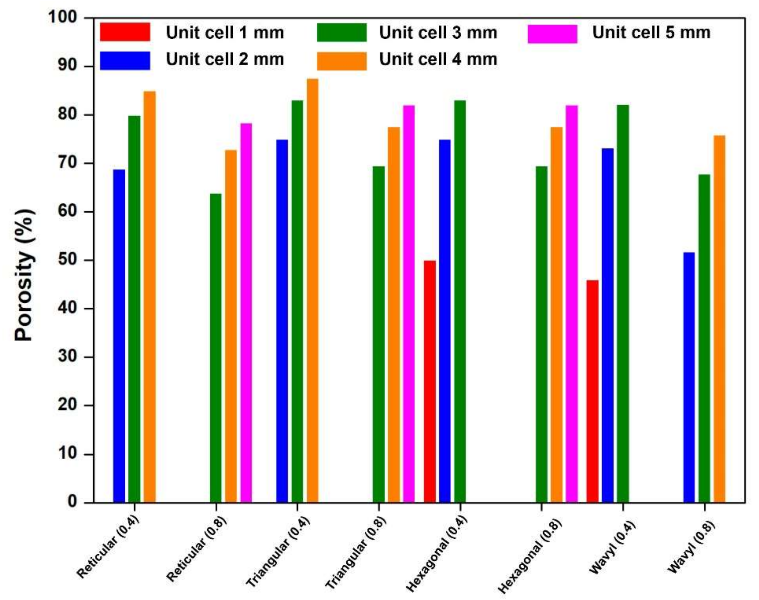
3.1. CAD-Based Scaffolds Design and Printability

Once unit cell configurations have been generated as a surface, the first procedure was to convert this into a three-dimensional form (see Figure S1 and Methods for further details). For triangular and hexagonal geometries, the scaffold consisted of 5 × 5 unit cell repetitions of 15 layers, while the reticular and wavy scaffolds consisted of 5 × 5 cell unit repetitions of 16 layers (Figure 1). Then such CAD models were 3D printed using Poly-ε-Caprolactone (PCL) as feedstock material in order to evaluate the printability of each scaffold by changing the nozzle diameter as a parameter of interest.
Starting from the 0.4 mm nozzle diameter, the minimum unit cell sizes allowed for printing were 2 mm for reticular and triangular geometries and 1 mm for hexagonal and wavy ones. Instead, the maximum value of unit cell achievable from such nozzle diameter was equal to 4 mm for reticular and triangular geometries and 3 mm for hexagonal and wavy (Figure S2A–D). In these unit cell ranges, the overall accuracy and quality of printed structures were optimal. On the contrary, a smaller unit cell size compared to the previously mentioned values led to a fusion of such scaffolds where the geometry can hardly be distinguished, and the shape and thickness of struts were inconsistent. Larger unit cell size strongly compromised the inner scaffold structure, leading to large voids generated from lack of material due to uncontrolled filament deposition during printing: extruded filament could not secure adhesion to the previous layers, and the printing failed.
For the lattice structures, 3D printed using a 0.8 mm nozzle, only larger unit cell sizes for each pattern can be printed successfully (Figure S2E–H). In particular, we were able to print unit cell sizes ranging from 3 mm up to 5 mm for reticular and triangular geometries and 2–4 mm for wavy and hexagonal structures. Because of a wider printed path, the manufacturability of smaller unit cell sizes was hampered, as this resulted in the scaffold structures melting.
Overall, with the use of either 0.4 mm or 0.8 mm nozzle diameter, it was possible to tune the unit cell sizes in order to obtain stable or well-defined lattice scaffolds that fully comply with FFF guidelines, avoiding stringing inside unit cells and lumps of filaments.
However, for the latter, we must keep in mind the extruder type (i.e., direct drive extruder and Bowden drive extruder) that could influence the outcomes of the overall structure. Briefly, the direct drive extruder has a direct drive gear close to the heating system and nozzle; hence the extrusion and retraction commands are more immediate, creating a more stable material deposition control and better resolution [35]. Contrary, in the Bowden drive extruder, the drive gear is installed outside the extruder head [35].
In order to handle such lattice structures based on the type of extruder available, the retraction settings must be adjusted to control the flow and the correct filament deposition. In this case, adopting the Sharebot QXXL 3D printer (see Materials and Methods for further details), we had a direct drive extruder, and the optimal retraction distance and retraction speed were 0.5 mm and 4200 mm min−1, respectively. In the case of using Bowden drive extruder, with PCL as feedstock material, for obtaining the same accuracy in the deposition of filament (and therefore the same final lattice scaffolds), high values of retraction were needed to prevent unnecessary extrusion while the extruder travels between printed sections. Specifically, such settings must be of 6 mm and 4800 mm min−1 for retraction distance and retraction speed, respectively (data not shown).
Next, we examined the porosity of CAD-based lattice scaffolds by varying the unit cell types as it can affect the topology of the entire structure, the fluid flow, cell ingrowth, vascularization, nutrition/oxygen supply, and energy absorption. Analyzing the data, it can be clearly seen for all scaffold architectures that the porosity increases linearly as the unit cell size increases, as would be expected (Figure 2). In addition, for the same unit cell size, the porosity of the 3D printed scaffolds with the 0.8 mm nozzle is always lower than those with the 0.4 mm. It should be emphasized that all scaffolds are highly porous, ranging from 46% (for wavy scaffold with 1 mm unit cell) to 87.50% (for triangular scaffold with 4 mm unit cell).
Overall, these data demonstrate a relationship between unit cell size and lattice structures, which is useful for fine-tuning the properties of scaffolds for tissue engineering, 3D cell cultures, bio-robotics, and orthopedics, but also to select which structure and which unit cell is most suitable for a specific use. It is further believed that by fine-tuning the lattice CAD models and/or adjusting the base unit cell size, a greater number of effective lattice gradients can be realized, allowing increased flexibility while adjusting the porosity for a given scaffold thickness.

3.2. FEM Analysis

For linear FEM analysis, the elastic modulus of PCL filament was considered to be equal to 350 MPa, and the Poisson’s ratio was set to 0.3 (see Materials and Methods).
A simple mesh sensitivity analysis was performed in order to obtain a plateau value of the compression and shear modulus for each tested scaffold. The FE model was generated with a mesh size of 0.5 mm, thus obtaining a number of finite elements of the order of 105. The elastic modulus was used in the FEM models with the assumption of linear elastic deformation, the FEM analysis was performed for each scaffold, and the mechanical behavior under compression was simulated. The distribution of von Mises stress for comparing the scaffolds with different geometries and nozzle diameters is shown in Figure 3. It is interesting to note that in the reticular, triangular, and wavy scaffolds, when subjected to stress, we have noticed the increase in the compressive elastic modulus due to the existence of thicker load columns. Conversely, the amount of maximum stress for the hexagonal scaffolds was lower than those of other scaffolds due to the absence of proper supporting columns. We assumed that the design parameters could influence the bonding strength between layers and filaments in the printed scaffolds, and the layer bonding of the hexagonal scaffold could be significantly weaker compared to other tested scaffolds because in every three layers, their contact points shifted, which could result in a decrease of the bonding strength.
Using the FEM simulation, the amount of force after completion of analysis was obtained, and the equivalent compressive elastic modulus was calculated by the ratio of compressive stress to compressive strain (see Equation (2) in the Materials and Methods).
The elastic modulus calculation showed how the mechanical properties of each scaffold could be strongly influenced by nozzle diameter and unit cell sizes (Figure 4). The compressive elastic moduli of the scaffolds with different geometries were predicted to have a broad range from 0.07 to 116.48 MPa. This range can be controlled by the design parameters such as unit cell size, geometries, porosity, nozzle diameter, and feedstock material. Considering a similar pattern—with the same unit cell size—it is possible to notice an increasing value of compressive modulus for the nozzle 0.8 mm compared to that of 0.4 mm. Instead, for the same path width, by increasing the unit cell sizes, the compressive features tend to decrease, thus weakening the scaffolds.
Leaving out the highest compressive moduli of wavy and hexagonal geometries at 1 mm of unit cell size (due to the lower void content in the scaffolds), taking into consideration the unit cell of 2 mm, it is highlighted that the more rigid structure is guaranteed by the reticular geometry (33.92 MPa) while the triangular and wavy patterns possess similar moduli (27.61 MPa and 28.8 MPa, respectively); this difference between patterns is maintained even with larger unit cells and larger print paths (Table 1). Rather, the hexagonal pattern displayed compression moduli of an order of magnitude lower than the other geometries, and this, as mentioned above, is due to the absence of thicker load columns.
In addition, the shear modulus of each microstructure was estimated by simulating shear tests on each scaffold in two lateral directions (Figure 5 and Figure S3). We observed that the values of shear moduli for reticular and wavy scaffolds have no directional dependence, probably due to the symmetry in their geometries. On the contrary, the triangular and hexagonal scaffolds have an uneven elastic modulus in lateral directions, with the elastic moduli slightly different from x- to y-direction (Table S1).
Altogether, shear moduli were dependent on both the type of geometries and unit cell sizes. Moreover, shear moduli of reticular and wavy scaffolds were similar in x- and y-direction, showing the highest shear moduli to compared other structures due to their supporting load columns; on the contrary, triangular and hexagonal scaffolds have the highest shear modulus in y-direction; on the contrary, the decreased value in x-direction was probably because of the highest amount of inter-layer contact points in these directions.
Lastly, we sought to estimate the compressive behavior of such lattice scaffolds via nonlinear FEM analysis (Figure 6A–D), using the Van der Waals hyperelastic model (see Materials and Methods for further details), as this model would better describe the material behavior of PCL filament [31]. Here, the compressive moduli of different scaffolds were calculated considering the initial and final point of the simulation, for a strain of 5%, since for all models, the compressive moduli were similar in small strain ranges but, by increasing the strain value, the stress–strain curves tend to diverge, showing a softening (Figure 6E).
The results showed that minimum variations of compressive modulus are registered for hexagonal geometries, where a difference close to 0 has been observed for all unit cell sizes. Higher softening is registered for reticular, wavy, and triangular geometries, with a variation ranging from 10 to 18%. Additionally, in this case, the reticular scaffolds resulted the stiffer, followed by wavy and triangular, whereas the hexagonal scaffolds remained the softer structures, maintaining almost the same compressive moduli with respect to the linear model (Table 2).
Overall, the nonlinear results showed that all PCL-based lattice structures with different unit cell sizes demonstrated hyperelastic behavior under compression. Nevertheless, we are aware that to better understand the nonlinearities in such structures would be useful to carry out predictive FEM analysis both with various load models and with higher strain ranges, coupled with experimental data.

3.3. Spectroscopy Characterization of 3D Printed Scaffolds

To explore if printing parameters could influence the chemical structures of PCL-based lattice scaffolds, which play an important role in the scaffolds overall behavior (such as biodegradation rate, crystallinity, and morphology), we carried out Raman spectroscopy analysis (Figure 6F). Raman spectra of lattice scaffolds printed with 0.4 and 0.8 mm nozzle diameter exhibited a similar peak pattern with minimal intensity changes at 915 and 961 cm−1 (in blue) associated with C-COO stretching, and three narrow bands at 1033 cm−1, 1066 cm−1, and 1110 cm−1 (in light green) associated with C-C stretching. Some other bands are visible approximately at 1284 and 1301 cm−1 (in magenta) due to the symmetric CH2 stretching, and at 1419 cm−1, 1443 cm−1, and 1468 cm−1 (in purple) ascribable to CH2 bending; lastly, a peak was observed at 1722 cm−1 (in orange) due to C=O stretching vibration.
In summary, this spectroscopic characterization seems to suggest that the printing parameters do not alter the chemical structures of such lattice scaffolds.

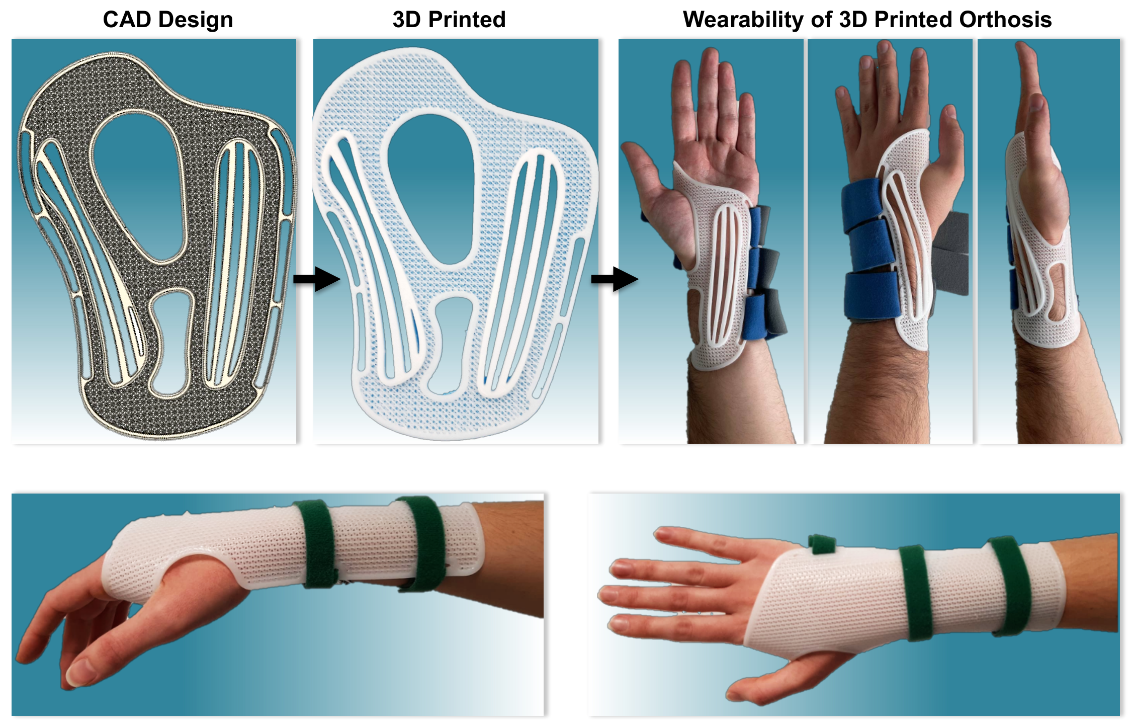
3.4. 3D Printed Wrist Brace Orthosis with Different Lattice Geometries

Finally, we wondered if these results allowed us to go beyond the manufacturability of scaffolds for tissue engineering. The results obtained enabled us to develop 3D printed wrist and hand brace orthosis made up of lattice structures that might be minimally invasive (but stiffer enough to support the limb), lightweight, and breathable (due to the possibility of fine-tuning the porosity of such structures). In recent years, 3D printing has offered an innovative method for rapid and customizable prototyping in the biomedical field, making these advantages possible. However, it is seldom discussed in the fields of hand rehabilitation, and many clinicians and hand therapists are still unaware of how this technology could be a useful and effective tool in the rehabilitation of patients with neuromuscular disease, rheumatoid arthritis, and beyond [36]. Therefore, to shed some light on the grey areas, we envisioned how to engineer novel orthosis with lattice geometries (Figure 7). Since reticular and triangular geometries provided better results both in terms of mechanical properties and porosity, we have chosen them to design the wrist and hand orthosis. Briefly, the 3D printed lattice structure orthosis has been created using Autodesk Inventor®. The procedure to obtain the final device was divided into two different phases: after the measurement of the anatomic region of interest, all data are collected to draw the first representation of the orthosis. Then, via extrusion, the edges of the orthosis and the reinforced portions are created. Subsequently, linear repetition of lattice geometry was created and cut to fit the inner boundary of the drawn orthosis. Finally, combining the boundary with the selected pattern, it is possible to export it in stereolithography (STL) format and slice it using Simplify3D® software. The final 3D printed orthosis was 4 mm thick, weighed <20 g, and possessed breathability >80%.
Surprisingly, the combination of PCL as feedstock material and lattice geometries with tunable mechanical features allowed us to obtain shape-memory orthosis. Such property is of particular interest as by using these structures coupled to PCL, it is no longer necessary to thermoform the polymer (as required for PLA, for instance), but on the contrary, PCL-based orthosis immediately takes the shape of the limb and gets back to its original shape once removed from the limb. This proof of concept gives us the impetus to test and validate these orthoses in future works.

4. Conclusions

In conclusion, we reported the design data and printing parameters for 3D printing of functional PCL-based lattice structures that fully comply with FFF guidelines are capable of bearing different compressive and shear loads, and with tunable porosity.
Based on the 3D CAD models, the scaffolds with four types of designed geometries (reticular, triangular, hexagonal, and wavy) were fabricated through FDM, elucidating the key value of the nozzle diameter and unit cell sizes in order to obtain stable or well-defined lattice scaffolds avoiding stringing inside unit cells and lumps of filament.
Further, we demonstrated that the FEM combined with 3D printing has the potential to predict the mechanical features of the scaffolds either in linear or nonlinear models, useful to select the most appropriate geometry, unit cell size, and nozzle diameter for a specific need without any fabrication, thus offering a new tool for designing specific devices with tunable mechanical behavior and porosity for tissue engineering, 3D cell cultures, controlled drug-release, medical devices, soft robotics, and beyond the usefulness of the PCL-based 3D printed lattice scaffolds for the fabrication of stiffer, lightweight, and breathable wrist and hand brace orthosis is demonstrated.

Supplementary Materials

The following are available online at https://www.mdpi.com/article/10.3390/eng3010002/s1, Figure S1: Explanation picture about the quantities reported in Equations (2) and (3), Figure S2: 3D printed PCL-based geometries with different nozzle diameters, Figure S3: The von Mises stress–strain distributions in the simulated shear test by FEM in the y-directions, Table S1: Comparison of shear moduli of four types of scaffolds with different nozzle diameter and unit cell sizes.

Author Contributions

Conceptualization, R.P.; methodology, R.S. and R.P.; software, R.S. and R.P.; validation, R.S. and R.P.; formal analysis, R.S. and R.P.; investigation, R.P. and R.S.; data curation, R.S.; writing—original draft preparation, R.P.; writing—review and editing, R.S., S.R. and R.P.; visualization, R.P.; supervision, R.P.; project administration, R.P.; funding acquisition, S.R. and R.P. All authors have read and agreed to the published version of the manuscript.

Funding

This research received no external funding.

Data Availability Statement

The authors confirm that the data supporting the findings of this study are available within the article [and/or] its Supplementary Materials.

Acknowledgments

We are grateful to Rotary Club Milano Linate for the financial support of 3D printing technology. R.P. is thankful to Arturo Donghi and Marzia Pezzali from Sharebot for their technical support and helpful discussion.

Conflicts of Interest

The authors declare no conflict of interest.

References

  1. Zhang, Q.; Zhang, K.; Hu, G. Smart three-dimensional lightweight structure triggered from a thin composite sheet via 3D printing technique. Sci. Rep. 2016, 6, 22431. [Google Scholar] [CrossRef] [PubMed] [Green Version]
  2. Koteswari, S.; Narayan Yeole, S. Development of 3D printed orthotic device for flat foot problem. Mater. Today Proc. 2021, 44, 2435–2441. [Google Scholar] [CrossRef]
  3. Martorelli, M.; Gloria, A.; Bignardi, C.; Calì, M.; Maietta, S. Design of additively manufactured lattice structures for biomedical applications. J. Healthc. Eng. 2020, 2020, 2707560. [Google Scholar] [CrossRef] [PubMed]
  4. Hutmacher, D.W. Scaffold design and fabrication technologies for engineering tissues—State of the art and future perspectives. J. Biomater. Sci. Polym. Ed. 2001, 12, 107–124. [Google Scholar] [CrossRef]
  5. Vijayavenkataraman, S.; Zhang, L.; Zhang, S.; Fuh, J.Y.H.; Lu, W.F. Triply periodic minimal surfaces sheet scaffolds for tissue engineering applications: An optimization approach toward biomimetic scaffold design. ACS Appl. Bio Mater. 2018, 1, 259–269. [Google Scholar] [CrossRef]
  6. Zhou, M.; Hou, J.; Zhang, G.; Luo, C.; Zeng, Y.; Mou, S.; Xiao, P.; Zhong, A.; Yuan, Q.; Yang, J.; et al. Tuning the mechanics of 3D-printed scaffolds by crystal lattice-like structural design for breast tissue engineering. Biofabrication 2019, 12, 015023. [Google Scholar] [CrossRef] [PubMed]
  7. Hollister, S.J. Porous scaffold design for tissue engineering. Nat. Mater. 2005, 4, 518–524. [Google Scholar] [CrossRef]
  8. Roohani-Esfahani, S.I.; Newman, P.; Zreiqat, H. Design and fabrication of 3D printed scaffolds with a mechanical strength comparable to cortical bone to repair large bone defects. Sci. Rep. 2016, 6, 19468. [Google Scholar] [CrossRef] [PubMed] [Green Version]
  9. Alomar, Z.; Concli, F. Compressive behavior assessment of a newly developed circular cell-based lattice structure. Mater. Des. 2021, 205, 109716. [Google Scholar] [CrossRef]
  10. Kantaros, A.; Piromalis, D. Fabricating lattice structures via 3D printing: The case of porous bio-engineered scaffolds. Appl. Mech. 2021, 2, 289–302. [Google Scholar] [CrossRef]
  11. Yoo, D. New paradigms in internal architecture design and freeform fabrication of tissue engineering porous scaffolds. Med. Eng. Phys. 2012, 34, 762–776. [Google Scholar] [CrossRef] [PubMed]
  12. Bagheri, A.; Buj-Corral, I.; Ferrer, M.; Pastor, M.M.; Roure, F. Determination of the elasticity modulus of 3D-printed octet-truss structures for use in porous prosthesis implants. Materials 2018, 11, 2420. [Google Scholar] [CrossRef] [PubMed] [Green Version]
  13. Bennett, I.; Bulterys, P.L.; Chang, M.; DeSimone, J.M.; Fralick, J.; Herring, M.; Kabaria, H.; Kong, C.S.; Larson, B.; Lu, O.; et al. The rapid deployment of a 3D printed “latticed” nasopharyngeal swab for COVID-19 testing made using digital light synthesis. medRxiv 2020, 44, 1361–1368. [Google Scholar]
  14. Wong, K.C. 3D-printed patient-specific applications in orthopedics. Orthop. Res. Rev. 2016, 8, 57–66. [Google Scholar] [CrossRef] [Green Version]
  15. Yap, Y.L.; Sing, S.L.; Yeong, W.Y. A review of 3D printing processes and materials for soft robotics. Rapid Prototyp. J. 2020, 26, 1345–1361. [Google Scholar] [CrossRef]
  16. Shen, Z.; Chen, F.; Zhu, X.; Yong, K.-T.; Gu, G. Stimuli-responsive functional materials for soft robotics. J. Mater. Chem. B 2020, 8, 8972–8991. [Google Scholar] [CrossRef] [PubMed]
  17. Keneth, E.S.; Kamyshny, A.; Totaro, M.; Beccai, L.; Magdassi, S. 3D printing materials for soft robotics. Adv. Mater. 2021, 33, 2003387. [Google Scholar] [CrossRef]
  18. Buswell, R.; Soar, R.; Gibb, A.; Thorpe, A. Freeform construction: Mega-scale rapid manufacturing for construction. Autom. Constr. 2007, 16, 224–231. [Google Scholar] [CrossRef] [Green Version]
  19. Maconachie, T.; Leary, M.; Lozanovski, B.; Zhang, X.; Qian, M.; Faruque, O.; Brandt, M. SLM lattice structures: Properties, performance, applications and challenges. Mater. Des. 2019, 183, 108137. [Google Scholar] [CrossRef]
  20. Jadayel, M.; Khameneifar, F. Improving geometric accuracy of 3D printed parts using 3D metrology feedback and mesh morphing. J. Manuf. Mater. Process. 2020, 4, 112. [Google Scholar] [CrossRef]
  21. Austermann, J.; Redmann, A.J.; Dahmen, V.; Quintanilla, A.L.; Mecham, S.J.; Osswald, T.A. Fiber-reinforced composite sandwich structures by co-curing with additive manufactured epoxy lattices. J. Compos. Sci. 2019, 3, 53. [Google Scholar] [CrossRef] [Green Version]
  22. Tao, W.; Leu, M.C. Design of lattice structure for additive manufacturing. IEEE Xplore 2016, 325–332. [Google Scholar]
  23. Chen, W.; Zheng, X.; Liu, S. Finite-element-mesh based method for modeling and optimization of lattice structures for additive manufacturing. Materials 2018, 11, 2073. [Google Scholar] [CrossRef] [PubMed] [Green Version]
  24. Boniotti, L.; Beretta, S.; Foletti, S.; Patriarca, L. Strain concentrations in BCC micro lattices obtained by AM. Proc. Struct. Integr. 2017, 7, 166–173. [Google Scholar] [CrossRef]
  25. Gümrük, R.; Mines, R.A.W. Compressive behaviour of stainless steel micro-lattice structures. Int. J. Mech. Sci. 2013, 68, 125–139. [Google Scholar] [CrossRef]
  26. Pugliese, R.; Beltrami, B.; Regondi, S.; Lunetta, C. Polymeric biomaterials for 3D printing in medicine: An overview. Ann. 3D Print. Med. 2021, 2, 100011. [Google Scholar] [CrossRef]
  27. Panetta, J.; Zhou, Q.; Malomo, L.; Pietroni, N.; Cignoni, P.; Zorin, D. Elastic textures for additive fabrication. ACM Trans. Graph. 2015, 34, 135. [Google Scholar] [CrossRef] [Green Version]
  28. Silva, R.; Torres, M.; Viñuela, J.; Zamora, A. Manufacturing and characterization of 3D miniature polymer lattice structures using fused filament fabrication. Polymers 2021, 13, 635. [Google Scholar] [CrossRef]
  29. Olubamiji, A.D.; Izadifar, Z.; Si, J.L.; Cooper, D.M.; Eames, B.F.; Chen, D.X. Modulating mechanical behaviour of 3D-printed cartilage-mimetic PCL scaffolds: Influence of molecular weight and pore geometry. Biofabrication 2016, 8, 025020. [Google Scholar] [CrossRef]
  30. Eshraghi, S.; Das, S. Micromechanical finite-element modeling and experimental characterization of the compressive mechanical properties of polycaprolactone-hydroxyapatite composite scaffolds prepared by selective laser sintering for bone tissue engineering. Acta Biomater. 2012, 8, 3138–3143. [Google Scholar] [CrossRef] [Green Version]
  31. Soufivand, A.A.; Abolfathi, N.; Hashemi, S.A.; Le, S.J. Prediction of mechanical behavior of 3D bioprinted tissue-engineered T scaffolds using finite element method (FEM) analysis. Addit. Manuf. 2020, 33, 101181. [Google Scholar] [CrossRef]
  32. Şerban, D.A.; Marşavina, L.; Silberschmidt, V. Behaviour of semi-crystalline thermoplastic polymers: Experimental studies and simulations. Comput. Mater. Sci. 2012, 52, 139–146. [Google Scholar] [CrossRef]
  33. Abbasi, A.A.; Ahmadian, M.T.; Alizadeh, S.T.A. Application of hyperelastic models in mechanical properties prediction of mouse oocyte and embryo cells at large deformations. In Proceedings of the ASME 2016 International Mechanical Engineering Congress and Exposition, Phoenix, AZ, USA, 11–17 November 2016. [Google Scholar]
  34. Kondo, T.; Hashimoto, R.; Ohrui, Y.; Sekioka, R.; Nogami, T.; Muta, F.; Seto, Y. Analysis of chemical warfare agents by portable Raman spectrometer with both 785nm and 1064nm excitation. Forensic Sci. Int. 2018, 291, 23–38. [Google Scholar] [CrossRef] [PubMed]
  35. Tlegenov, Y.; Hong, G.S.; Lu, W.F. Nozzle condition monitoring in 3D printing. Robot. Comput. Integr. Manuf. 2018, 54, 45–55. [Google Scholar] [CrossRef]
  36. Patterson, R.M.; Salatin, B.; Janson, R.; Salinas, S.P.; Mullins, M.J.S. A current snapshot of the state of 3D printing in hand rehabilitation. J. Hand. Ther. 2020, 33, 156–163. [Google Scholar] [CrossRef]
Figure 1. CAD models of designed lattice structures. (AD) Top and 3D views of CAD design of four types of lattice geometries (A) reticular, (B) triangular, (C) hexagonal, and (D) wavy and related images of the 3D printed scaffolds.
Eng 03 00002 g001
Figure 2. Theoretical porosity of different lattice scaffolds. Porosity of each CAD model obtained by measuring the occupied volume of each scaffold.
Eng 03 00002 g002
Figure 3. FEM models under compression. Von Mises stress distribution of lattice scaffolds with different geometries and nozzle diameters. The stress value increases from blue to red colors. In orange, the top view magnification of stressed scaffold; in red and green, the magnification of load columns.
Eng 03 00002 g003
Figure 4. FEM-derived elastic modulus calculation. Elastic moduli of scaffolds with different microstructures and nozzle diameters obtained from FEM simulations.
Eng 03 00002 g004
Figure 5. FEM-derived shear moduli. The von Mises stress–strain distribution in the simulated shear test by FEM in the lateral x-direction and estimation of shear moduli of scaffolds with different microstructures.
Eng 03 00002 g005
Figure 6. FEM prediction of compressive behavior of PCL scaffolds with Van der Waals models. (AD) Estimation of compressive moduli of scaffolds with different geometries using nonlinear vs. linear model; (E) prediction of nonlinear compressive behavior of lattice structure using van der Waals hyperelastic model and its comparison with linear compression data. (F) Raman spectroscopic analysis of lattice scaffold made of PCL printed with 0.4 mm (in blue) and 0.8 mm (in red) nozzle diameters. (A.U., arbitrary unit).
Eng 03 00002 g006
Figure 7. CAD design and wearability of 3D printed lattice-based orthosis. Representative images of shape memory 3D printed orthosis with reticular (upper images) and triangular (below images) lattice structures.
Eng 03 00002 g007
Table 1. Comparison of compressive elastic moduli (Ecomp) in the linear model of four types of scaffolds with different nozzle diameters and unit cell sizes.
Unit Cell Size (mm)Ecomp Reticular (MPa)Ecomp Triangular (MPa)Ecomp Hexagonal (MPa)Ecomp Wavy (MPa)
1 (nozzle 0.4)--100.74116.48
2 (nozzle 0.4)33.9227.613.4628.80
3 (nozzle 0.4)14.4711.930.3412.80
4 (nozzle 0.4)7.806.69--
5 (nozzle 0.4)----
1 (nozzle 0.8)---
2 (nozzle 0.8)---88.00
3 (nozzle 0.8)40.2533.052.2538.40
4 (nozzle 0.8)22.0418.430.2821.40
5 (nozzle 0.8)14.5211.700.07-
Table 2. Compressive elastic moduli from the linear model in comparison with the Van der Waals nonlinear hyperelastic model.
EcompLinearNonlinearLinearNonlinearLinearNonlinearLinearNonlinear
Unit Cell Size (mm)Reticular (MPa)Triangular (MPa)Hexagonal (MPa)Wavy (MPa)
1 (nozzle 0.4)----100.7489.86116.48101
2 (nozzle 0.4)33.9229.8527.6124.073.463.3928.8025
3 (nozzle 0.4)14.4711.9811.9310.280.340.3412.8011.11
4 (nozzle 0.4)7.806.386.695.74----
5 (nozzle 0.4)--------
1 (nozzle 0.8)--------
2 (nozzle 0.8)------88.0077.5
3 (nozzle 0.8)40.2535.1833.0528.632.252.1838.4033.56
4 (nozzle 0.8)22.0419.1818,4315.90.280.2921.418.73
5 (nozzle 0.8)14.5212.2811.710.140.070.07--
Publisher’s Note: MDPI stays neutral with regard to jurisdictional claims in published maps and institutional affiliations.

