Article

Towards a Better Understanding of Concrete Arch Dam Behavior during the First Filling of the Reservoir

by
Noemi Schclar Leitão
1,*,
Eloísa Castilho
2 and
M. Luísa Braga Farinha
1
1
Laboratório Nacional de Engenharia Civil (LNEC), Av. do Brasil, 101, 1700-066 Lisbon, Portugal
2
Instituto Superior Técnico, Universidade de Lisboa, Av. Rovisco Pais, 1049-001 Lisbon, Portugal
*
Author to whom correspondence should be addressed.
CivilEng 2023, 4(1), 151-173; https://doi.org/10.3390/civileng4010010
Submission received: 29 December 2022 / Revised: 28 January 2023 / Accepted: 30 January 2023 / Published: 3 February 2023
(This article belongs to the Section Structural and Earthquake Engineering)

Abstract

:
During the first filling, the reservoir is gradually raised in multiple stages. At each stage, the filling is paused to allow adequate time for monitoring and evaluating the performance of the dam and its foundation. The analysis of the monitored behavior and assessment of security conditions is performed by comparing the values measured by the monitoring system installed in the dam with the values predicted by numerical models representing the structural behavior, the material properties, and the loads. This article addresses the main aspects related to the safety control of concrete arch dams during the first filling of the reservoir. Special attention is given to the nonlinear behavior induced by the opening/closing of the contraction joints. An example of numerical simulation of the behavior of an arch dam during the first filling of the reservoir is also presented. The validation of the computed temperatures, the induced displacements and the induced stresses was performed by comparison with the values measured with the monitoring system installed in the dam.

1. Introduction

The first filling of a reservoir can be defined as the increase in water level upstream from the dam from the time that the construction is complete until the water reaches the desired operating level. The first filling of a reservoir should be planned, controlled, and closely monitored in order to reduce the risk of failure [1]. Therefore, the reservoir is gradually raised in multiple stages. At each stage, the filling is paused to allow adequate time for monitoring, data collection, and evaluating the performance of the dam and its foundation. The safety assessment is based on the comparison of the monitoring data with reference values. To this aim, it is necessary to develop models that allow for simulation of the expected dam response under the influence of the variations that occur in the dam’s environment [2].
In recent years, the initial impoundment of super-high arch dams in China, such as Xiaowan (294.5 m), Jinping I (305 m), and Xiloudu (285.5 m), stimulates the research into and development of several approaches in order to assess their behavior during reservoir water level increases.
Zhou et al. [3,4] used thermo-mechanical finite element analysis (FEA) to assess the performance of Xiaowan dam during the initial impoundment. In their approach, the mechanical and thermal parameters are calibrated using an inversion method. Each time the difference between the measurements and the computed displacements exceeds the allowed tolerance, the parameters are updated following the process shown in [4] (p. 2465). The objective function for the mechanical parameters is based on the hydrostatic component of the monitored displacements extracted by regression analysis. The temperature load is defined as the difference between the sealing temperature and the computed temperature.
For Jinping I dam’s initial impoundment, Wu et al. [5] analyzed only the effect of the water level component. However, Liu et al. [6] used a complete thermal-hydro-mechanical FEA model. In their approach, the thermal model follows the guidelines outlined by Zhu in [7], mainly that the hydration heat is modelled in adiabatic conditions and the exchange of temperature with the environment considers an increase in air temperature to simulate the solar radiation. The mechanical model considers the nonlinear behavior of the contraction joints and uses an incremental scheme to deal with the time-dependent effects of the viscoelastic behavior of the concrete.
Li et al. [8] used a thermal-mechanical FEA model to assess the behavior of Xiloudu dam. The thermal model assumes an exponential expression for the hydration heat (adiabatic condition), an equivalent heat source for the artificial cooling, convective boundary conditions for the exposed surfaces, and fixed boundary conditions for the surfaces in contact with water. The mechanical model adopts a continuous linear behavior using an equivalent elastic module to represent the creep.
Other examples of the thermo-mechanical modelling of concrete dams can be seen in the review presented by Salazar et al. [9], who have summarized the different criteria used by the authors for decision-making in the construction of the model. Unfortunately, not all the works correspond to real cases, nor do they perform a comparison of the computed values with monitored data. Therefore, in those cases, it is impossible to draw conclusions about their physical representativeness.
In previous works, Leitão et al. [10] and Leitão and Castilho [11] used thermal-mechanical FEA for the safety assessment of Alto Ceira II dam and Foz Tua dam during the initial impounding. Both works refer to the information provided by the numerical models in order to help the decision-making process before proceeding to follow the filling of the reservoir.
According to the Portuguese Regulation for the Safety of Dams, after the initial impoundment, a more detailed study about the interpretation of the observed dam behavior must be carried out. This study allows for a better understanding of the dam in question and promotes improved design and evaluations in the future.
Based on the experience gained in modelling concrete arch dams, this paper describes the main issues concerning the structural and heat transfer analysis necessary to obtain a more representative behavior of the dam during the first filling of the reservoir. Special attention is given to the nonlinear behavior induced by the opening/closing of the contraction joints.
In contrast to the analyses presented previously [10,11], the case study reported in this work corresponds to the more detailed analysis carried out for the final evaluation of the dam. Therefore, as the reported analysis begins with the construction of the dam, the simulation of the evolution of the hydration reaction and the viscoelastic behavior were taken into account. The validation of the computed temperatures and the induced displacements and stresses was performed by comparison with the values registered by the monitoring system installed in the dam.

2. Analysis Considerations

2.1. Behavior Model Selection

As has been mentioned, the safety assessment is based on the comparison of the monitoring data with reference values. In order to obtain reference values, several different types of models have been used. These models can rely on past experience (data-driven models), on a logical mathematical formalization of the laws that the structure is thought to obey (physics-based models) and, lastly, on both of those considerations together (hybrid models) [2].
On the one hand, the availability of a large and diverse volume of monitoring data has generated a lot of interest in data-driven approaches. Many behavior models either based on statistical prediction or based on machine learning (ML) techniques have been proposed. The statistical models have been widely used for the data analysis of concrete dams since the 1950s. The most popular one is the hydrostatic-seasonal-time (HST) model introduced by Willm and Beaujoint in 1967 [12]. However, because during the first years of life different non-stationary phenomena affect the response of the dam, the HST model can only be used some years after construction [13]. To overcome this limitation, Hu and Ma [14] have recently proposed two improved models to tackle the non-stationary thermal and the non-monotonic time-dependent effects. Conversely, models based on ML algorithms are intrinsically more suitable to reproduce non-linear effects and complex interactions between input variables and dam response [15]. However, they are typically unable to produce accurate results beyond the range of the training data. Therefore, since the first filling of the reservoir is the first loading experience of the dam, such training data is not available at the time of the initial impoundment.
On the other hand, physics-based models, also known as deterministic models, are based on the physical laws governing the involved phenomena. Each phenomenon can be expressed with the help of algebraic, differential, or integral equations. Nowadays, FEA is a frequently used computational approach for problems with complicated geometries, loadings, and material properties where analytical solutions cannot be obtained. Although they can be very accurate, the users must be aware that the success of FEA simulations relies on the understanding of the physics, which govern the problem, and the numerical process going on at the backend of the FEA solver.
Apart from the inherent issues of data-driven models that advise against using them during the initial impoundment, it is important to note that, since they are not based on physical laws, they do not allow for the understanding and explanation of the different phenomena that are involved in a dam’s behavior. Therefore, FEA is the most effective way for the physical comprehension of a dam’s behavior and the correspondent safety assessment during the initial impounding.

2.2. Useful Features of the FEA Solvers

In order to simulate the first years of dam’s life, it is recommendable that the tools used for FEA satisfy certain requirements, such as the following:
  • Mesh updating at each construction stage;
  • Formworks modelling;
  • Spatial and temporal distribution of the structure temperature T ( x , y , z , t ) ;
  • Simulation of the evolution of the hydration reaction;
  • Simulation of the artificial cooling;
  • Properly modelling of joints in the dam and in the foundation mass;
  • Simulation of the time-dependent response of concrete supported on appropriate creep laws;
  • Use of restart files to continue an interrupted simulation;
  • User-friendly interfaces to provide an effective communication between user and FEA.

2.3. Meshing

Although most mesh generation schemes are based on a tetrahedral meshing algorithm, it is worthwhile to make an effort to construct meshes of hexahedron quadratic solid elements to represent the dam. They are naturally suited to the representation of vertical contraction joints and horizontal concreting lifts, allowing a proper simulation of construction sequence, as illustrated in Figure 1. This figure represents the construction simulation of the Alqueva dam, which is an arch dam with a maximum height of 96 m and a total length of 348 m between the abutments at the crest elevation [16].
Mesh size is one of the key questions to be solved; a more refined mesh usually means more accurate results, but the computing time becomes significantly higher as well. It is important to apply St Venant’s principle whenever possible [17], as it greatly reduces analysis time. In fact, it is always advisable to use a sparse mesh for global assessment of the dam/foundation system and, if necessary, to use a sub-modelling technique in specific regions. It is very important not to lose sight of the fact that as impoundment progresses, the analysis could need to be rerun with upgraded material parameters in order to capture the real behavior.

2.4. Thermal Analysis

The heat flowing inside a dam and the heat entering and leaving the dam are governed by different mechanisms. The heat inside the dam moves by conduction and it is treated as the governing equation expressed by the heat conduction equation. The heat entering or escaping the dam moves by convection, or radiation, or both, and it is usually considered as a boundary condition.
To represent the heat release due to the hydration reaction, different analytical expressions as a function of time, simulating the evolution of heat in adiabatic conditions, have been proposed. However, under practical circumstances, the hydration does not evolve adiabatically, and the heat source is significantly affected by the actual values of the temperatures that develop inside the concrete. Therefore, the time parameter alone is not enough to correctly describe the progress of the hydration reaction. The mutual dependency between the rate of hydration and the concrete temperature implies that the calculation of both the temperature development and the hardening process are to be carried out using a stepwise calculation procedure in which the effect of the actual temperature and the rate of reaction are modelled explicitly [18].
As regards climatic actions, solar radiation and convection heat transfer are the two of the main factors that affect temperature distribution on the surfaces of dams. Three-dimensional analysis is particularly relevant in the thermal analysis of arch dams as, due to the curved geometry of this type of structures, there are areas of the upstream and downstream surfaces of the dam that do not absorb solar radiation, depending on their inclination.

2.5. Nonlinear Structural Analysis

2.5.1. Contraction Joints

A concrete arch dam is constructed as a system of monolithic blocks separated by contraction joints. The monoliths are constructed separately so that cooling and shrinkage may take place independently in each one. After the construction period, the contraction joints are grouted under high pressure with the aim of forming a complete monolithic structure.
However, contrary to the conventional view that grouting of contraction joints brings monolithic behavior to dams, joint-meters reveal that contraction joints continue working through the entire dam’s lifespan, since grouted joints can take little or no tension.
Therefore, although the use of interface or joint elements to represent the vertical joints has been mainly related to the dynamic analysis, it is obvious that even when a static analysis is performed, the use of linear elastic numerical models can mislead the interpretation of the entire structure response [19,20].
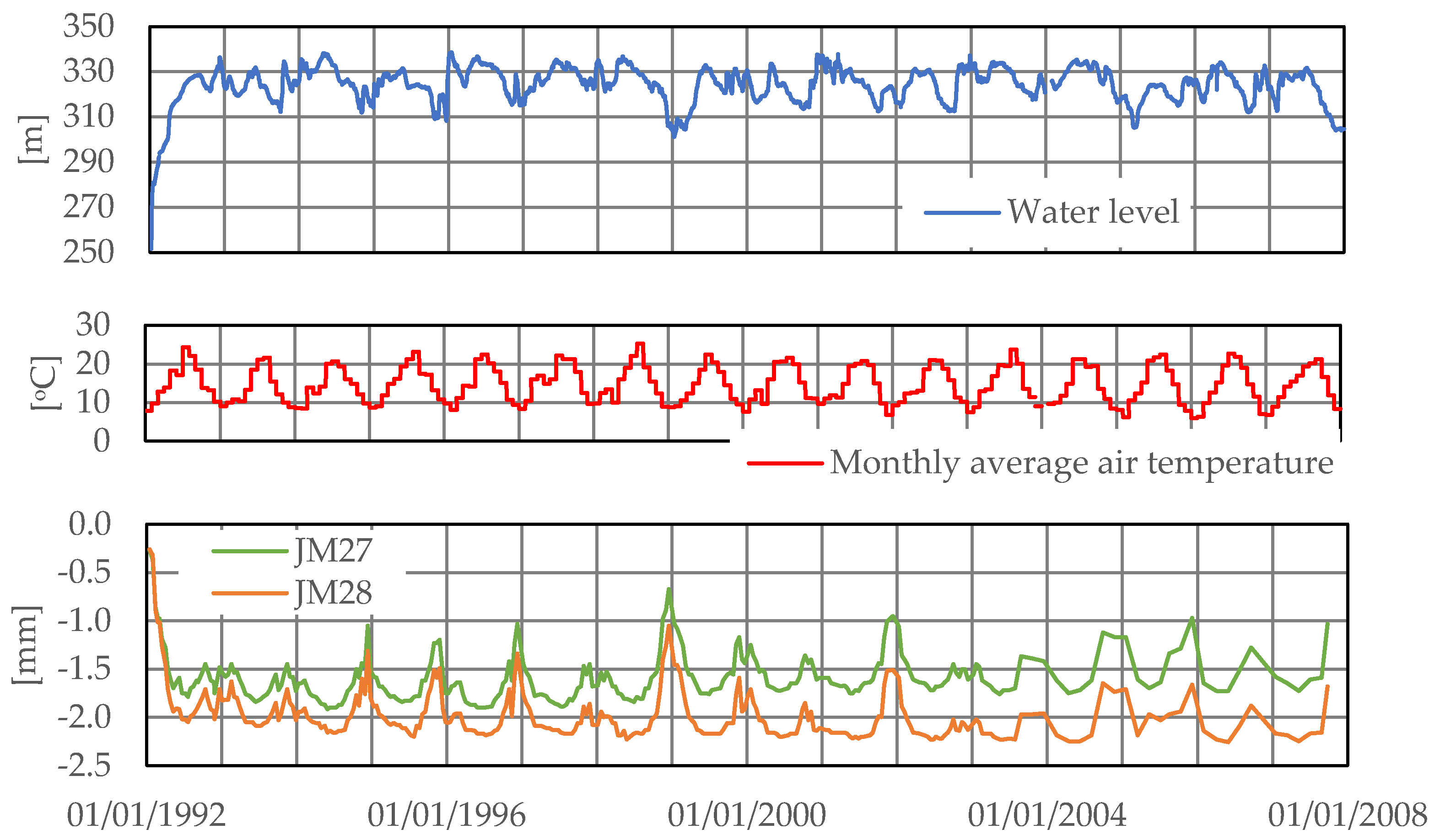
Figure 2 shows the typical movements registered by two joint-meters installed close to the crest of an arch dam. Both devices are installed at the same contraction joint; JM27 is located near the upstream surface of the dam and JM28 is located near the downstream surface.
Actually, there are two useful observations from Figure 2. The first one is that vertical joints open and close in response to yearly temperature changes and level fluctuation, confirming that joints work during the entire lifespan. The second one is that, considering that contraction joints have only a few millimeters of thickness, it is impossible that grout experiences a “contraction” of almost 2 mm during the initial impounding. The only way of obtaining a contraction joint closing of almost 2 mm is if a previous opening had taken place somewhere in between the grouting and the beginning of the first filling.
It follows from the above that it is important to initiate the analysis, at least, as soon as the grouting is finished, in order to capture the opening of the contraction joints.

2.5.2. Dam–Foundation Interface

High tensile stresses can be expected to occur mainly at the upstream heel due to the water load exerted by the reservoir, leading to crack formation. These cracks are usually stable, as long as shear stresses do not exceed the shear strength of mass concrete and rock. However, if the crack at the base of a dam opens, the deformations of the dam will increase, resulting in a redistribution of the stresses, thus, increasing the arch stresses [21].
To capture the influence of such disconnection between the dam heel and its foundation, interface elements between the base of the dam and the rock mass foundation are often used in numerical models. Although this approach is accurate enough, one must bear in mind that cracks can also appear in joints of the rock mass located below the dam or even along a defective horizontal concreting lift of the dam itself [22].
Moreover, interface elements between the dam and the rock mass foundation have to be defined if uplift load must be considered in the analysis.

2.5.3. Interface Elements

It is worth noting that although sophisticated interface elements, mainly developed for dynamic analysis [23], offer the possibility of including shear key properties, initial tensile stress, initial gap, etc., they have the drawback that the determination of these parameters is a very difficult task. Therefore, it is wise to keep the joint model as simple as possible in order to avoid introducing more uncertainties than is necessary.
As mentioned previously, the adopted model should estimate the expected behavior. Then, joint opening due to no-tension strength is a normal behavior and should be modelled. Conversely, sliding movement due to shear failure is not an expected behavior and, therefore, there is no need to model it.
Convergence issues are frequently triggered by interface elements. The easy way to overcome this problem is to go back to the restart file, that is the last converged result, and rerun the analysis with a smaller time step. Since instabilities are usually associated with steep load changes, the use of smaller time steps (real or fictitious) allows for applying the load variation gradually in order to avoid convergence troubles.

2.6. Creep

According to ICOLD [24] the special conditions of concrete in dams, as for example the high temperature in the body mass and the high sustained load (self-weight) at early ages, lead to a larger creep effect in dams than in other civil structures and, therefore, it needs a careful estimation.
In practice, there are three ways to represent the creep deformation, as follows: (i) the creep coefficient φ ( t , t ) which expresses the delay deformation with respect to the elastic strain; (ii) the specific creep C ( t , t ) which expresses only the delay strains due to the application of a unit stress; and (iii) the compliance function J ( t , t ) which represents the total strain caused by a constant unit stress acting since time t . In all the cases, the creep deformation is a function of the current age of the concrete t and the age at load application t .
With the purpose of guiding the selection of the most suitable method of analysis, Bažant and Jirásek [25] classify the structures in five levels of sensitivity, where level five requires the most realistic and accurate analysis based on the compliance function. According to that classification, large gravity, arch, or buttress dams correspond to level four, for which an accurate analysis is also necessary and is recommended, although not required.

2.7. Effective Communication between User and FEA

To simplify the user experience and to avoid cumbersome time conversions, it is strongly recommended that all transferring of times to or from the software be made using civil dates.
A simple transformation between civil dates and a continuous counting of time can be performed using the Julian day numbering scheme. The Julian day numbers, used by astronomers, express the number of days that have elapsed since the Greenwich mean noon of 1 January 4713 BC, which is midday as measured on the Greenwich meridian on 1 January of that year. In this way the Julian day number is a continuous count of days and fractions thereof from the beginning of the year 4713 BC. It is important to note that each new Julian day begins at 12 h 00 min UT (Universal Time), half a day out of step with the civil day in time zone 0 [26].
Another important issue is how to obtain results in monitoring points. In general, a finite elements solver provides information only at nodal or integration points. Since monitoring points do not usually coincide with mesh points, it will be necessary to map one field of points onto the other. Three types of mapping techniques can be employed for this purpose [27], namely node placement, approximation, and interpolation. In the first one, mesh nodes and monitoring points are forced to coincide. Since the accuracy of the FEA models is a function of node position, node placement techniques introduce an undesired coupling between the position of data points and the accuracy of the finite elements model. For the other two techniques, it must be taken into account that generic interpolation and approximation algorithms (for example, using linear, cubic, and B-spline weight functions) creates a dependency of the interpolated field to non-physical parameters. By contrast, interpolation techniques using FE shape functions make no assumptions other than those already introduced in the finite elements model.
More details on the implementation of the above features can be found in [28] and its companion library [29].

3. Case Study

3.1. General Description of the Project

Alto Ceira II dam was built in order to replace the original Alto Ceira dam, built in 1949, which was strongly affected by alkali–silica reactions.
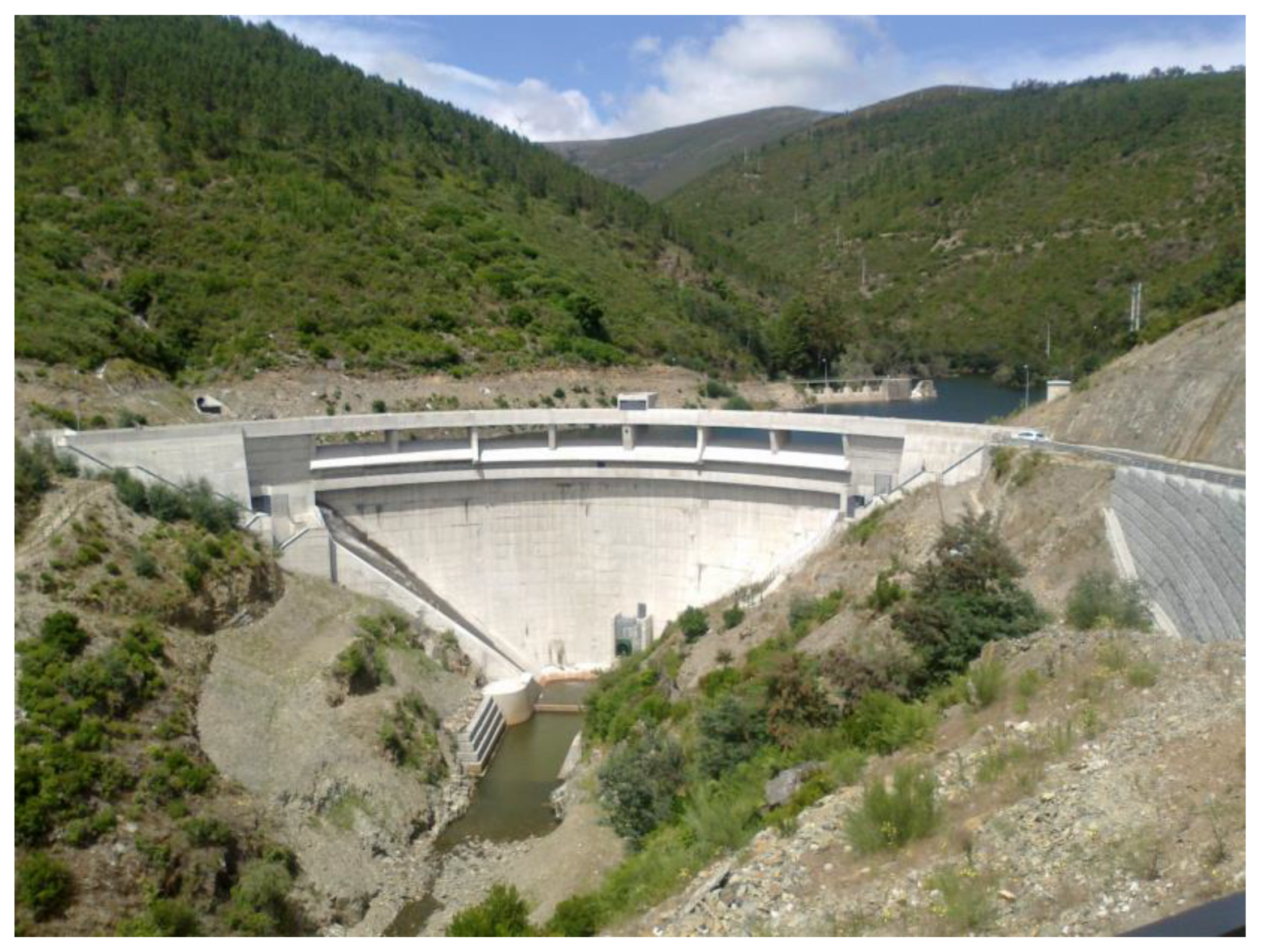
Alto Ceira II dam is a concrete double curvature arch dam with artificial gravity abutments. The total height above the foundation is 41 m, the crest length is 100 m, and the crest elevation is 668.50 m. Its shape definition is based on parabolic arches, which increase in thickness towards the abutments; the central cross section has a theoretical thickness of 2 m at the crest and 5.5 m at the base. The dam is divided into six independent concrete blocks along its longitudinal axes, the two central blocks with a width of 16 m, and the laterals blocks with a width of 17 m. The right gravity abutment is 20 m wide, and its height varies between 12 to 14 m. The left gravity abutment is 13 m wide, and its height varies between 7 to 11 m. The dam is shown in Figure 3.
The rock mass is schistous, displaying some areas of significant weathering at the top of the slopes. The schistosity is sub-vertical, dipping towards upstream, and approximately normal to the valley axis. Several discontinuities, mostly sub-horizontal or sub-vertical, were identified at the dam site. During the dam’s construction, two prominent rock discontinuities (one on each bank), that could cause problems to the dam-foundation safety, were identified, leading to additional excavation in the right bank in order to locate the right abutment foundation below the newly detected fault surface. This removed rock mass was replaced by concrete [30].
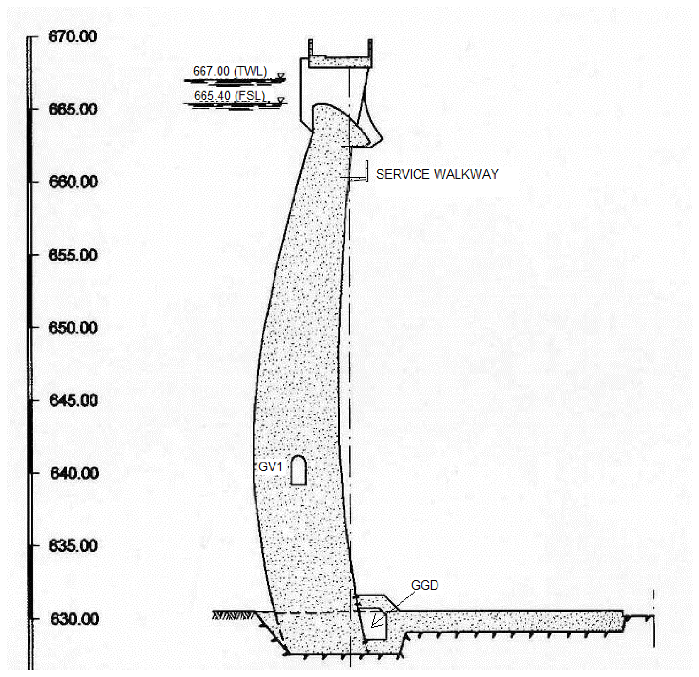
The reservoir has a total storage capacity of approximately 1.3 hm3 for the full storage level (FSL) at an elevation of 665.40 m, and 1.5 hm3 for the top water level (TWL) at an elevation of 667.00 m.
The dam is provided with a surface uncontrolled spillway along almost the whole crest of the dam and with a downstream stilling basin. Its maximum discharge capacity is of about 200 m3/s. The dam is also provided with a bottom outlet, located in the dam’s central zone, with a discharge capacity of 15 m3/s.
There are two longitudinal galleries, the foundation or drainage gallery (GGD), and an inspection gallery (GV1), located at elevation 639.15 m. There is also a service walkway at elevation 660.40 m (see Figure 4). The foundation gallery is an independent structure located immediately adjacent to the downstream toe of the dam and it provides access to seven transverse galleries located near the foundation of the blocks.
In order to identify the dam safety issues of concern throughout its lifetime, including the construction period, the first filling of the reservoir, and the operation phase, the monitoring system involves the following:
  • Measurement of the main loads and structural responses;
  • Periodic visual inspections to the dam, the surrounding rock mass, and the reservoir;
  • Characterization of the rock mass and concrete properties;
  • Development of models to simulate the dam/foundation behavior, in order to validate the monitoring data.
Figure 5 shows the instrumentation installed to monitor the structural responses due to static loads.
According to the Portuguese Regulation for the Safety of Dams, Alto Ceira II dam is classified as a Class I dam (high hazard potential).

3.2. Performance Assessment during the Initial Impoundment

The Portuguese Regulation for the Safety of Dams requires that the National Laboratory for Civil Engineering (LNEC) carries out the assessment of the structural stability of Class I dams during and after the initial impoundment. To this end, at each stage, short technical reports are prepared to present the main conclusions and recommendations before the filling of the reservoir. In addition, after the initial impoundment, a more detailed study about the interpretation of the observed dam behavior is presented in a final technical report.
Since Alto Ceira II dam was classified as Class I, the LNEC was deeply involved in the performance assessment during the initial impoundment. The main aspects related to the safety control of Alto Ceira II dam during the first filling of its reservoir are addressed in [10]. In the work presented here, a more comprehensive analysis carried out for the final technical report is presented. In the following analysis, the simulation begins in the construction phase and the parameters necessary to take into account, namely the evolution of the hydration reaction and the viscoelastic behavior of the concrete, are defined based on laboratory tests.

3.3. First Filling of the Reservoir

In order to reduce the risk of accidents or incidents during the first filling of the reservoir, the process was divided into four stages. In each stage, the rate of filling would be controlled to allow for the implementation of a predetermined surveillance program, including the observation and analysis of instrumentation. During the first stage established at elevation 642.00 m, level P1, work related to the demolition of the old dam would be carried out. The other three levels, corresponding to water level at elevations 658.50, 664.00, and 665.40 m, or levels P2, P3, and P4, respectively, were defined in order to obtain a hydrostatic pressure equal to 60%, 90%, and 100% of the full storage level, respectively.
The first filling of the reservoir began on 28 June 2013, and by 8 July the water level reached the first stage and was maintained during the summer. At the end of September, further requirements concerned with the process of the partial demolition of the old dam led to the establishment of an extra hold point at elevation 649.00 m. This hold point was called the equalization level (EQL) due to the fact that the level upstream and downstream of the old dam would be held at the same value to allow for the partial demolition of it. This level was achieved on 9 October, and it was maintained for several weeks.
Contrary to what was established, the period of severe rainstorms during late 2013 and early 2014 led to an uncontrollable rising of the reservoir, meaning that it reached the P2 level on 9 January, the P3 level on 4 February, and the P4 level on 11 February 2014.

3.4. Finite Element Model

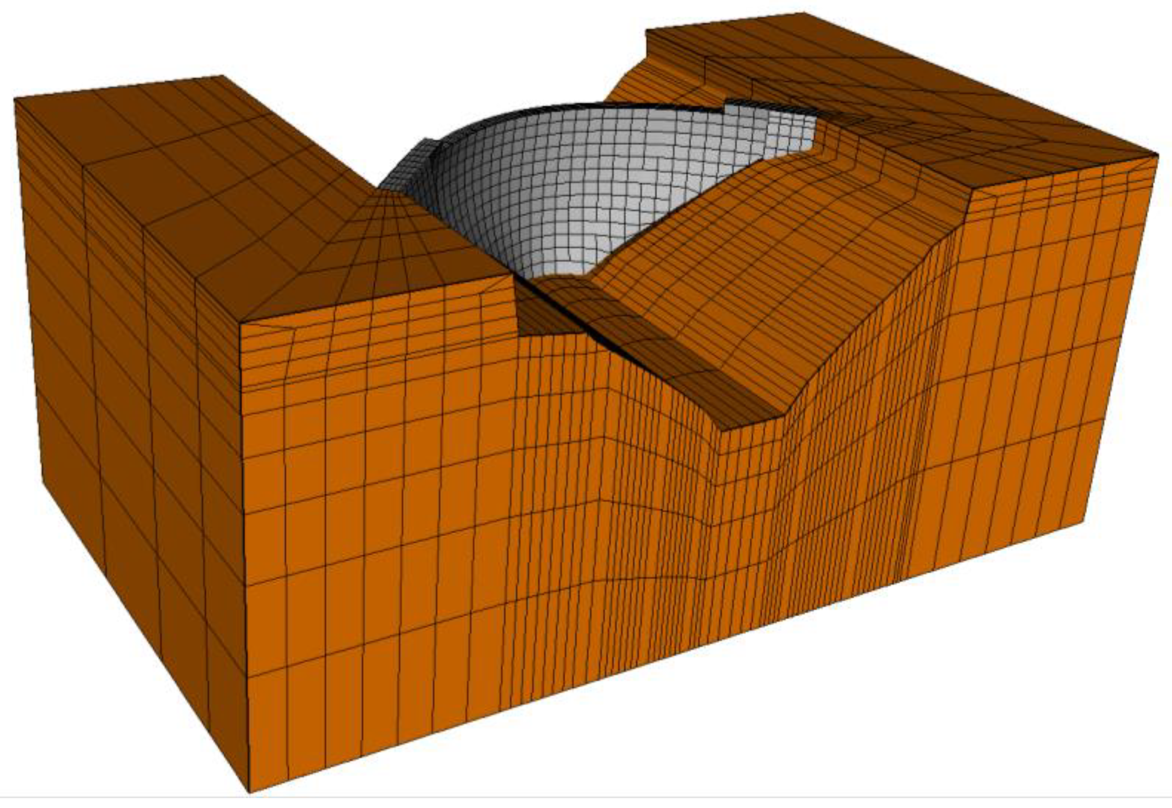
The finite element model represents the double-curvature concrete arch dam and an appropriate volume of the foundation, as shown in Figure 6.
The dam model comprises 4 layers of 20 node solid elements throughout its thickness, except for the gravity blocks on the abutments, which have 7 layers of elements. For practical reasons, the same solid elements mesh was used for both the thermal and the mechanical analysis.
For the mechanical analysis, the arch was divided into eight monoliths separated by radial vertical contraction joints. The contraction joints and the dam–foundation interface were represented by 16 node zero-thickness interface elements. The model is comprised of 7652 solid elements and 569 interface elements.

3.5. Thermal Analysis

3.5.1. Thermal Properties

Table 1 summarizes the rock mass foundation and concrete properties used in the thermal analysis.
The hydration kinetics model was formulated in the framework of thermodynamics of chemically reactive porous media based in the model presented by Ulm and Coussy [31]. Among the different empirical relationships used to represent the normalized affinity A ˜ ( ξ ) , the following one presented by Cervera et al. [32] was used:
A ˜ ( ξ ) = k ξ η ξ o ( A ξ o k ξ ξ + ξ ) ( ξ ξ )   exp ( η ¯   ξ ξ )
where ξ is the hydration degree, ξ is the asymptotic degree of hydration, and k ξ , A ξ o , k ξ   η ξ 0 , and η ¯ are material properties.
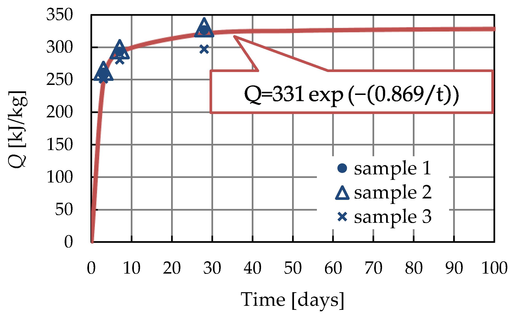
As part of the concrete quality assurance, three samples of cement were tested to determine the heat of hydration at the ages of 3, 7, and 28 days. These results and the best fitting S-shape function are presented in Figure 7.
The composition of the concrete used in the body of the dam was characterized by a cementitious content of 260 kg/m3, with 55% of fly ash and a ratio w/c = 0.55. To consider the reduction in the total heat of hydration produced by the replacement of a portion of the Portland cement with fly ash, the results obtained in [33] were taken into account, which shows that for 50% fly ash, the decrease in the heat of hydration is of approximately one-third. Then, applying the approach presented in [16], the following parameters were determined [34]:   ξ = 0.77; k ξ / η ξ o = 4 × 10⁵ h−1; A ξ o / k ξ = 1.04 × 10⁻², and η ¯ = 5.59.
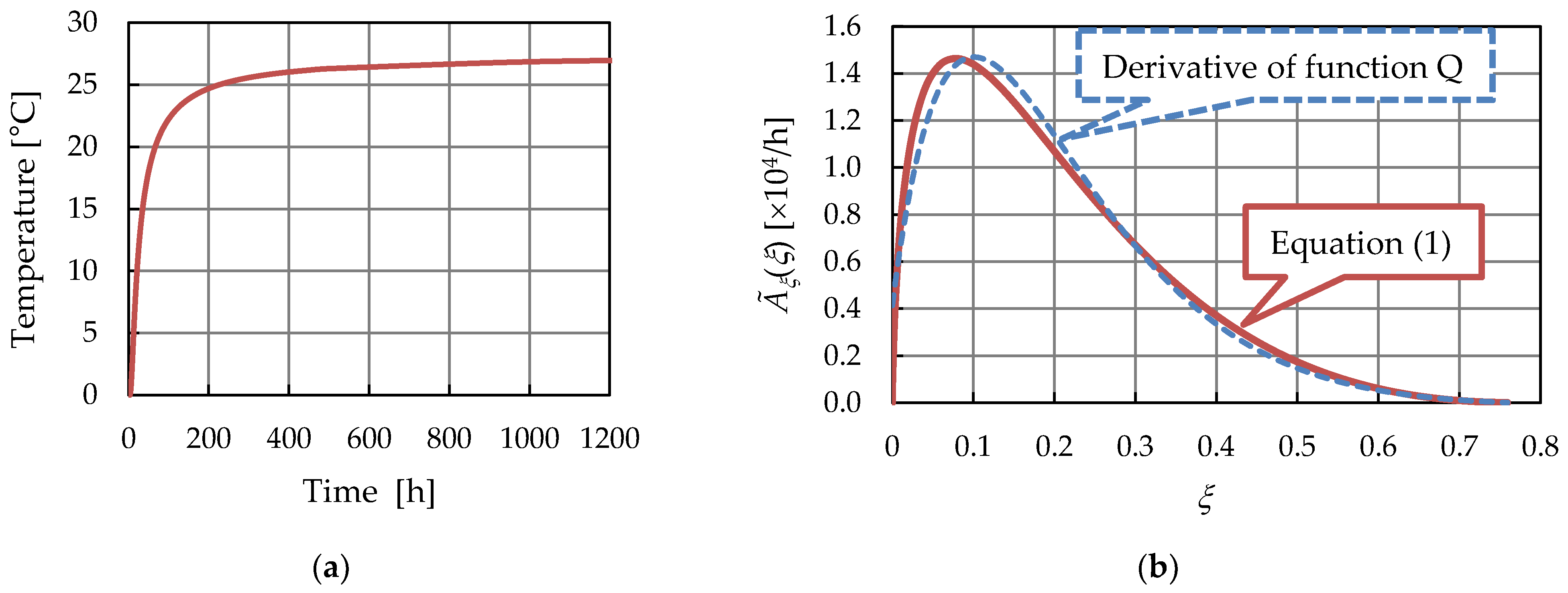
The adiabatic temperature increase and the normalized affinity obtained are illustrated in Figure 8. Figure 8b shows the comparison of the estimated normalized affinity based on the derivative of the S-shape function and the Cervera et al. analytical Expression (1) evaluated with the parameters defined previously.

3.5.2. Boundary Conditions

For the dam, convection/radiation heat transfer and solar radiation flux absorption boundary conditions, in all air-exposed boundaries, and fixed reservoir water temperature boundary conditions, in all submerged boundaries, were applied. For the rock mass foundation, convection/radiation heat transfer boundary conditions in all air-exposed boundaries were applied, along with adiabatic boundary conditions at the lateral boundaries and a fixed temperature boundary condition of 13 °C at the bottom.
The daily air temperature variation was estimated based on the minimum and maximum daily temperatures measured at the dam site. For each day it was assumed that the extreme temperatures occurred 12 h apart, at 03:00 h and 15:00 h for the minimum and maximum temperatures, respectively, and a linear variation was assumed between them.
The downstream face of the dam faces south-west with its axes forming an angle of 35° with the south. The solar irradiance was represented by an exponential function obtained from the graphics presented in [35] for the different Portuguese regions. Expression (2) is as follows:
I b cos Z = I o exp ( 0.968 + 0.760 cos Z )
where I b is the beam component of the solar radiation, Z solar zenith angle, and I o is the solar constant (1367 W/m2).
To consider the influence of other environmental factors, namely wind speed and cloud cover, the data obtained from Meteoblue [36] was considered during the first filling phase. To simplify the analysis, the period under study was divided into eight parts, each one characterized by similar mean values. Thus, the total heat transfer coefficient h t , which is a function of the average wind speed, ranges from 80 to 106 kJ/(m3 h °C). Taking into account that Expression (2) represents the average solar irradiance in the Serra da Estrela region, the influence of cloudiness was considered by using an equivalent concrete absorption coefficient varying between 0.45 and 0.65, that is, between dense cloud cover and clear sky, respectively. The increase and decrease in the concrete absorption coefficient, usually in the range of 0.5 to 0.6, was defined by calibrating the numerical model to obtain the temperatures measured by the thermometers installed in the dam.
For the construction phase, a constant value for the total heat transfer coefficient h t = 90 kJ/(m3 h °C) was applied to the whole model, except in the surface insulated by the formwork. Due to the lack of information about the formwork characteristics, an empirical value of 0.10 times the concrete total heat transfer coefficient was adopted, resulting in h t = 9 kJ/(m3 h 90 °C).
The water temperature of the reservoir was introduced as a prescribed temperature. For the first period of the impoundment, between 28 June 2013 and the P3 stage, on 4 February 2014, it was adopted as a constant value over the full depth and was approximately equal to the temperature recorded by the thermometer installed on the upstream face of the dam, in blocks J4–J5 at elevation 635.25 m. As the weather became warmer, thermal stratification started to occur in the near-surface water. Therefore, from the end of February, the approximated Function (3) was adopted for levels higher than 655.50 m, as follows:
T w a t e r ( y , d ) = T m w a t e r ( y ) T a w a t e r ( y )   cos { 2 π 365 [ d d o ( y ) ] }       [ ° C ]
with
T m w a t e r ( y ) = 3.86 + 9.93   exp ( 0.02 y )       [ ° C ]
T a w a t e r ( y ) = 5.00   exp ( 0.0167 y ) [ ° C ]
d o ( y ) = 114.31 85.12 exp ( 0.024 y ) [ days ]
where y is the depth of the water, d is the fractional day of the year, and T m w a t e r , T a w a t e r and d o are the annual mean temperature, the amplitude of annual variation, and the phase difference in water temperature at depth y , respectively.
A further description of how to apply the boundary conditions can be seen in [28] and its companion library [29].

3.5.3. Analysis and Results

The transient thermal analysis of the construction phase was performed with the code PATQ [16], developed by the first and second author, which applies a fully-implicit Euler backward finite difference scheme for the time discretization and a finite element scheme for the spatial discretization. Due to the dependence of hydration rate on temperature, a two-level iterative procedure was implemented. At the structural level, the iteration is due to the nonlinear dependence of the “thermal body force” on the temperature. At the local level (that is, at each integration point), the iteration is due to the nonlinear dependence of the degree of hydration (internal variable) on the temperature (free variable).
The simulation starts with the beginning of the construction on 22 June 2011. The finite element model of the dam was updated for every construction stage by applying the birth and death methods. The analysis was conducted considering an incremental time of 1 h.
The contraction joints were grouted during April 2013 without any artificial cooling. At that time, all the hydration heat had been released, and the thermal analysis of the first filling phase was carried out using the code PAT [28].
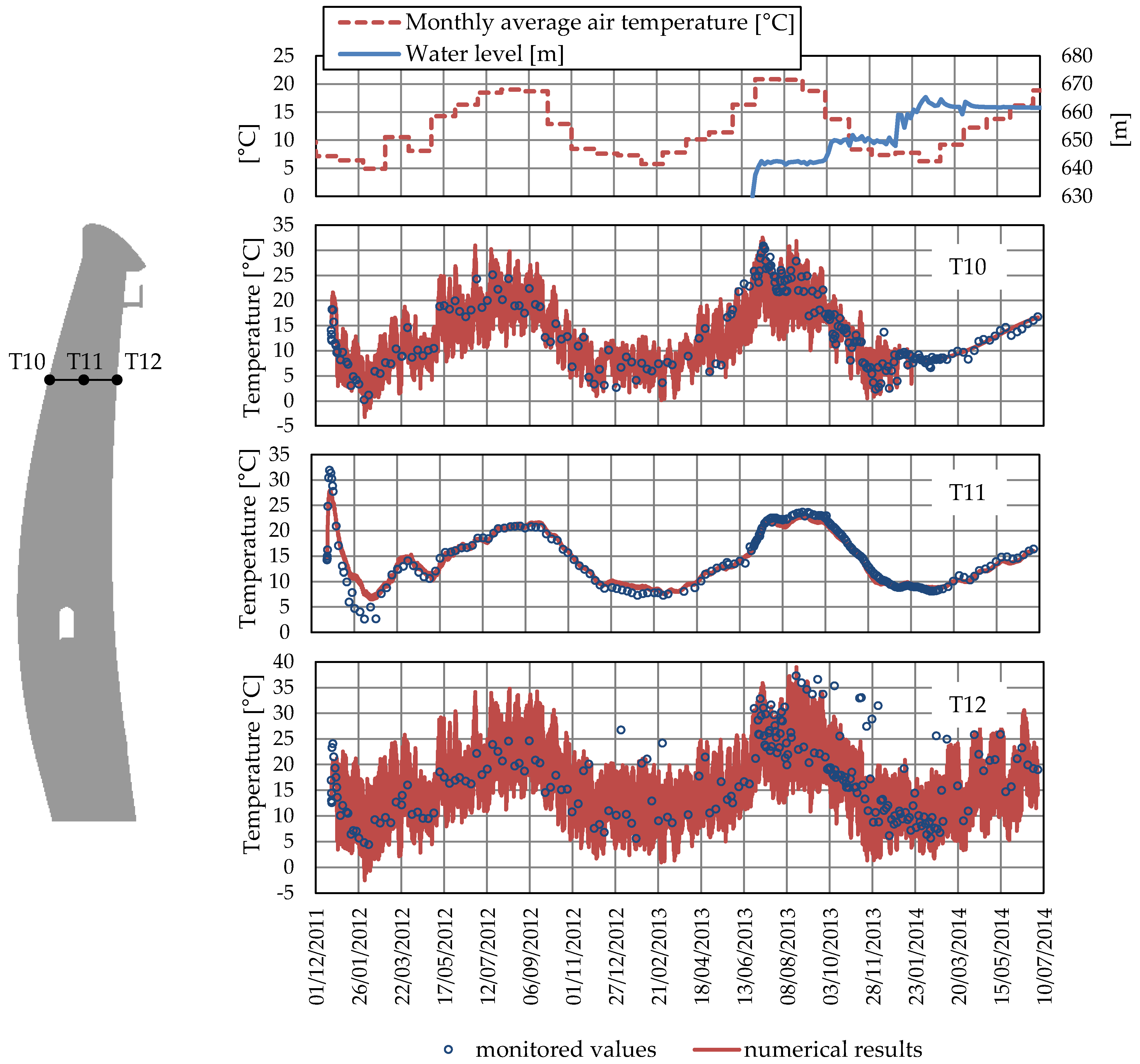
In order to validate the model, a comparison between predicted and measured temperatures was made. Figure 9 shows the comparison between recorded temperatures and those predicted with the numerical model in thermometers T10 to T12 located at elevation 656.00 m in blocks J4–J5.
In all comparisons a good agreement between numerically calculated and monitored values was achieved. This gave confidence that the thermal model was good enough to represent the temperature loads.

3.6. Mechanical Analysis

3.6.1. Mechanical Properties

Concrete creep was represented by the double power law [37,38,39,40,41,42]. Equation (7) is as follows:
J ( t t ) = 1 E o + φ 1 E o   ( t m + α ) ( t t ) n
where J ( t t ) is the compliance function (or the creep function), i.e., the strain at age t caused by a unit uniaxial constant stress acting since age t ; E o is the asymptotic modulus; n ,   m ,   α ,   and   φ 1 are material parameters. These parameters were adopted by taking into account the results obtained in the laboratory for creep test in samples at ages 28 and 32 days and for the modulus of elasticity at ages 28, 32, 90, and 365 days [34].
The rock mass foundation was considered as a linear elastic material.
The contraction joints and the dam–foundation interface were represented by zero-thickness interface elements. In this approach, the contact constraint is enforced by the penalty method, where the normal stiffness k n and the tangential stiffnesses k s   and k t play the role of penalty coefficients. This means that they have to be set as high as possible to guarantee that no penetration takes place while the joints are closed, but not so high as to avoid ill-posed problems. In this way, the normal and tangential stiffness have no physical meaning and, therefore, no additional experimental work is required. Moreover, the assumptions of no-tension and no-sliding conditions to characterize the normal and tangential behavior, respectively, also contribute to avoiding the need for extra material parameters.
Table 2 summarizes the material properties used in the mechanical analysis.

3.6.2. Loads

The analysis was conducted by considering dead load, hydrostatic load, and internal strains caused by temperature changes. Since Alto Ceira II dam is a thin arch dam, uplift load was ignored.

3.6.3. Analysis and Results

The mechanical problem was solved incrementally through time, considering both the construction and the initial impoundment phases. The analysis was carried out with the code PAVK, developed by the first author.
Similarly to the thermal codes PAT and PATQ, the structural code PAVK was developed following the structured programming style proposed by Smith and Griffiths [43] and using its companion library of subroutines [43]. With a view to covering concrete dam analysis, the code PAVK was provided with a library of selected elements, material models, and load cases appropriate for that purpose.
The element library comprises 2D and 3D isotropic elements, to represent the concrete and the rock foundation, and interface elements, to represent the contraction joints and the dam–foundation interface. The available material models are elasticity and viscoelasticity. Following [44], the integral stress–strain relation for viscoelasticity is replaced by a differential one (rate type formulation) based on the approximation of the compliance function by a Dirichlet series corresponding to a Kelvin rheological chain. The implemented interface elements correspond to a zero-thickness type.
Since the grouting of the contraction joints was performed during April 2013, the date 1 May 2013 was adopted as the limit between the construction phase and the first filling phase.
During the construction phase, from 22 June 2011 to 1 May 2013, the time intervals were constrained by the concreting and formwork striking dates. In order to have a good simulation of the concrete at an early age, the time between two consecutives concreting was divided into intervals uniformly distributed in a log ( t t ) scale, that is, intervals of 1, 10, and 100 days.
During the first filling phase, from 1 May 2013 to 2 July 2014, the analysis was carried out in regular intervals of two weeks, except when one of the initial impoundment levels (P0, P1, EQL, P2, P3, or P4) was reached.
For the construction phase, all the contraction joints were considered open, without any interaction between two consecutive blocks. On 1 May 2013, the displacements were reset to zero, simulating the grouting of the contraction joints, and the interface elements were activated. At this stage, the stress field was maintained unchanged, since the effect of the grouting pressure was considered practically negligible.
The analysis is carried out in stepwise manner, considering that at each time step the load increment occurred between the current and the previous time. It is worth mentioning that the activation of the interface elements in order to simulate the grouting of the contraction joints makes the transition from the independent cantilever behavior of each block during the construction phase to the interaction among them after that. In this way, there is no need to consider the grouting temperature as a reference temperature (zero stress condition), as it is adopted in the classical approach. Before grouting, thermal stresses develop only due to constrains at each individual block. After grouting, the activation of the interface elements also contemplates the block interaction constraints. Hence, the stresses obtained with the numerical model correspond to total stresses. However, as the displacements were set to zero after grouting, the computed values correspond to the displacement variations.
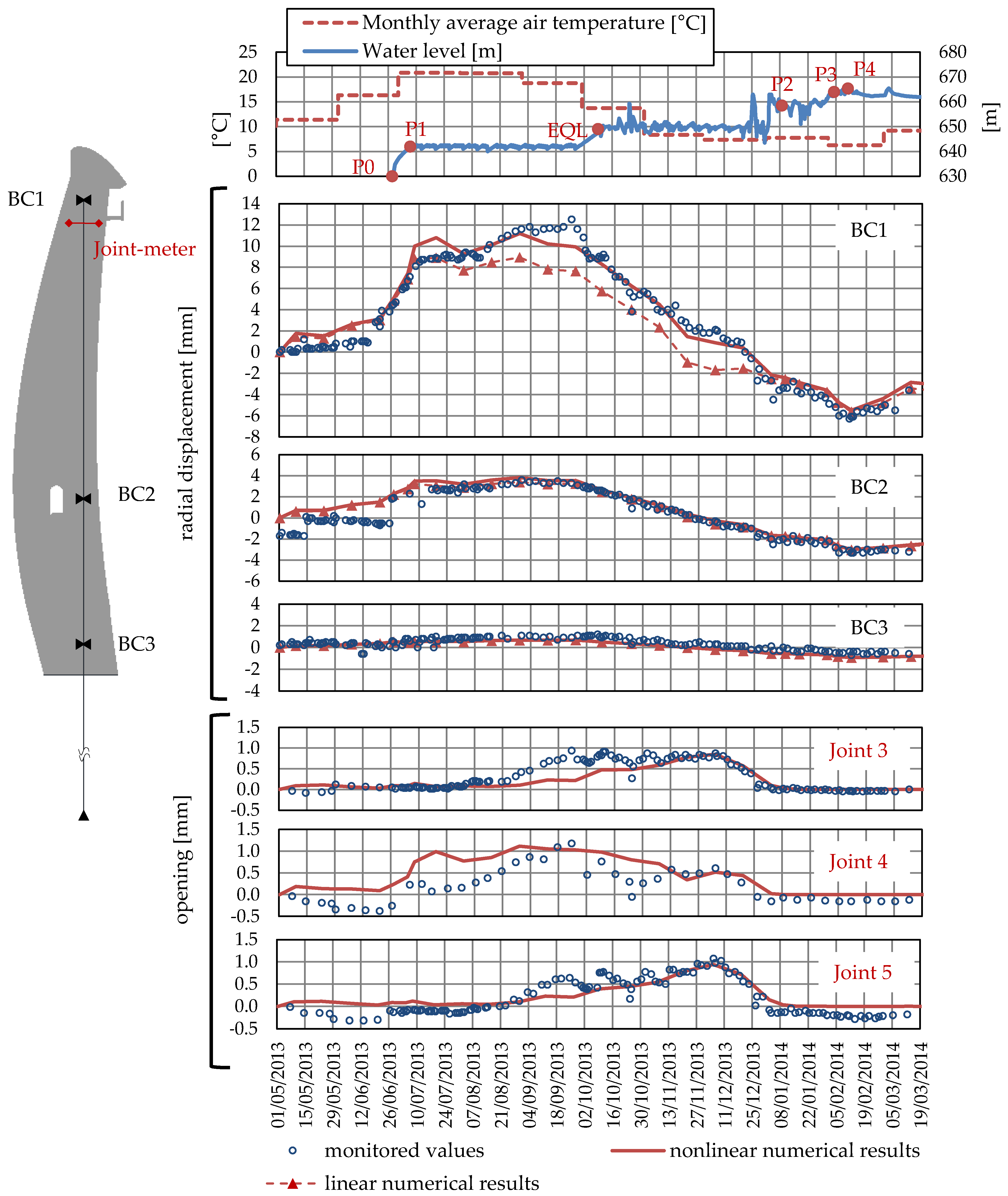
Figure 10 compares displacement obtained with the numerical model together with the corresponding values measured with the monitoring system installed in the dam. This figure shows, from top to bottom, in the first graph, the monthly average temperature, the rising reservoir water level, and the first filling stages; in the following three graphs, radial displacements are shown; and, in the last three graphs, the opening of the three central joints are displayed.
The radial displacements were computed at the same points as the pendulum reading stations BC1, BC2, and BC3, at elevations of 661.30 m, 640.40 m, and 629.73 m, respectively, in blocks J3–J4. These graphs also include the displacements obtained with a linear model to obtain a better understanding of the importance of representing contraction joints. It is worth noting that the initial monitoring values of BC2 were affected by a deficient coordinometer anchorage, which was settled meanwhile.
The opening of the contraction joints correspond to the three central joints, J3, J4, and J5, at elevations of 660.00 m, 655.50 m, and 660.00 m, respectively. The selected joint-meters are located at the middle of each section.
The analysis of these figures reveals that both models, the nonlinear and the linear one, predict almost similar results for displacements measured at reading stations BC2 and BC3, and that they show a good agreement with measured displacements. This can be explained by the fact that the contraction joints remain closed at lower elevations.
On the contrary, at reading station BC1, a very close agreement is obtained just before the water level reaches level P1, when contraction joint 4 starts to open. After that point, the two models show different behavior, getting back together again when the water level reaches level P2, which is coincident with the closing of the three contraction joints.
As can be seen in Figure 10 (joint 4 graph) the nonlinear model anticipates the opening of the contraction joint 4, leading to a worse agreement with the measured values during these two weeks. After that, the nonlinear model follows the measured openings for another two weeks, presenting a new disagreement which is coincident with the lower opening prediction of joints 3 and 5. Thereafter, the nonlinear model follows the measured openings again. The no-tension assumption, trouble convergence issues, and the insufficient refinement of the mesh can explain the disagreement between the computed and the measured behavior. However, in general, the nonlinear model presents a better performance than the linear model.
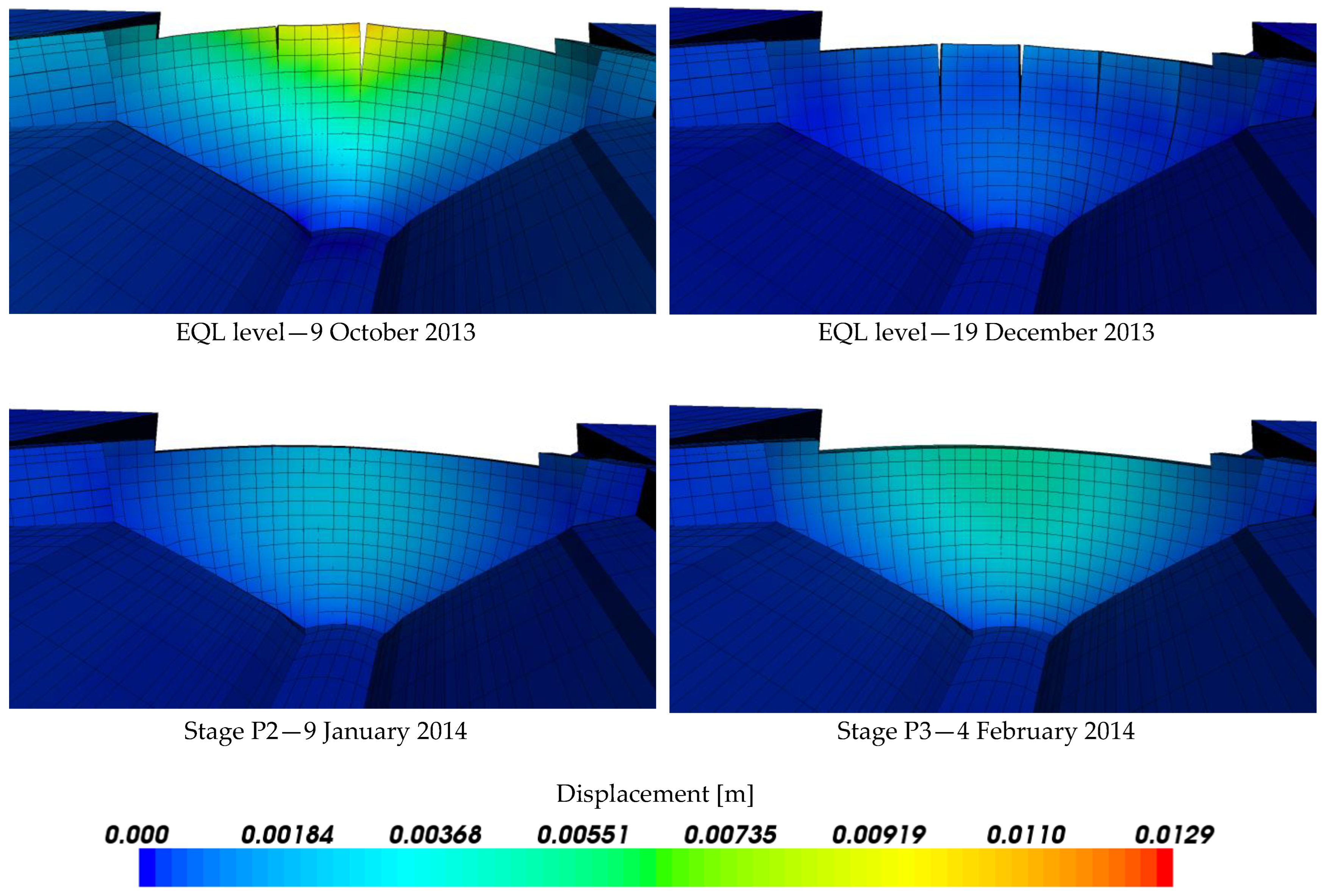
In Figure 11, some results considered representative of the contraction joints’ behavior during the first filling of the reservoir are presented. The colour contour plots represent the total displacements (modules), and the deformed mesh is represented with a scale factor of 1000. As was mentioned before, at the beginning of the first filling of the reservoir the joints were generally closed, which explains why both models, with and without joints, exhibited similar results and were coincident with the observed values. In July, the central joint starts to open, followed by the lateral joints of the central blocks. This situation lasted until the increase in the water level of the reservoir to the P2 level, after which the dam resumed its monolithic behavior.
Finally, Figure 12 shows the comparison between the stresses obtained with the numerical model and the stresses computed from the strain measured with the strain-meter rosettes installed at 1 m from the surface of the dam at blocks J4–J5. Each rosette is composed by five strain meters, four 45° apart in a plane parallel to the dam surface, and one normal to that plane. To correct the strain from changes induced by factors other than stress, an extra no-stress strain meter was installed in the vicinity of each rosette.
As can be seen from Figure 12, the arch stresses at 1 m from the upstream surface, at rosettes G3, G5, and G7, clearly reflect the increase in negative stresses (compression stresses) with the closing of the contraction joints when water reached level P2. After that, the variation of arch stresses is induced by temperature variation, with a decrease in compression following the rise in the water temperature (see Figure 9, thermometer T10). Near the downstream surface, the arch stresses computed using strain rosettes G6 and G8 show a great influence from the changes in air temperature. These results are typical of a restrained structure, where compressive forces develop due to thermal expansions.

4. Discussion and Conclusions

A chemo-thermal model based on the chemical affinity concept was applied to the analysis of the temperature distribution during the construction phase of a concrete arch dam. In the absence of specific adiabatic calorimetric tests of the concrete mixes used in the dam, an exponential function was calibrated, taking into account the heat of hydration of the cement at 3, 7, and 28 days. The exponential function obtained was then used to construct the Cervera et al. [32] chemical affinity relationship. The use of the chemical affinity concept allowed a more precise representation of the mutual dependency between the rate of hydration and the concrete temperature [18]. The representation of this dependency is more important in thin arch dams, where the adiabatic conditions assumed in earlier approaches is hardly satisfied.
Another important feature of the temperature analysis is the use of the Sun–Earth geometry relationships to compute the solar radiation effect. Although it may seem quite cumbersome, it is important to note that the implementation of this feature is generic and can be carried out in advance. In fact, once implemented, users have only to input the latitude and azimuth angles, as well as the solar irradiance data (see [28]). Moreover, this methodology is much more accurate than the old procedure of increasing the air temperature, which does not take into account the real curved geometry of the arch dam. In this respect, it is important to note that the amount of incident solar radiation on a surface depends on the angle formed by the incident solar radiation and the normal to the surface [28].
A nonlinear viscoelastic analysis was carried out to obtain the structural response of the dam. The contraction joints and the dam–foundation interface were modelled using zero-thickness interface elements under no-tension and no-sliding conditions, thus, avoiding the need to determine new material parameters. Even though these are idealized conditions, the model produces acceptable results and allows for understanding the real behavior of the contraction joints during the initial impoundment. The comparison of the opening/closing of the contraction joints between model results and monitoring values corroborates the validity of the nonlinear model.
It should be stressed that, although the calibration of the Young’s modulus at each stage can yield what appears to be an acceptable correlation with field-measured displacements, this is not a correct model. The apparent Young’s modulus increase (rigidity increase) is in fact due to the closure of the contraction joints.

Author Contributions

Conceptualization, N.S.L.; methodology, N.S.L.; software, N.S.L. and E.C.; validation, N.S.L. and E.C.; formal analysis, N.S.L.; investigation, N.S.L., E.C., and M.L.B.F.; writing—original draft preparation, N.S.L. and M.L.B.F.; writing—review and editing, N.S.L. and M.L.B.F.; visualization, N.S.L.; supervision, N.S.L. All authors have read and agreed to the published version of the manuscript.

Funding

This research received no external funding.

Data Availability Statement

The data presented in this study are available in the article.

Conflicts of Interest

The authors declare no conflict of interest.

References

  1. Association of State Dam Safety Officials. Lessons Learned from Dam Incidents and Failures. Available online: https://damfailures.org/lessons-learned/the-first-filling-of-a-reservoir-should-be-planned-controlled-and-monitored/ (accessed on 23 November 2022).
  2. ICOLD. Dam Surveillance Guide; International Commission on Large Dams Bulletin 158; CRC Press/Balkema: Leiden, The Netherlands, 2018. [Google Scholar]
  3. Zhou, Q.; Zhang, G.; Li, H.; Liu, Y.; Yang, B. Study on Regression Analysis and Simulation Feedback-Prediction Methods of Super High Arch Dam during Construction and First Impounding Process. In Earth and Space 2012: Engineering, Science, Construction, and Operations in Challenging Environments; Zacny, K., Malla, R.B., Binienda, W., Eds.; ASCE: Reston, VA, USA, 2012; pp. 1024–1033. [Google Scholar] [CrossRef]
  4. Zhou, Q.; Zhang, G.X.; Liu, Y. Prediction of and Early Warning for Deformation and Stress in the Xiaowan Arch Dam during the First Impounding Stage. Appl. Mech. Mater. 2013, 405–408, 2463–2472. [Google Scholar] [CrossRef]
  5. Wu, S.; Cao, W.; Zheng, J. Analysis of Working Behavior of Jinping-I Arch Dam during Initial Impoundment. Water Sci. Eng. 2016, 9, 240–248. [Google Scholar] [CrossRef]
  6. Liu, Y.; Zhang, G.; Zhu, B.; Shang, F. Actual Working Performance Assessment of Super-High Arch Dams. J. Perform. Constr. Facil. 2016, 30, 04015011. [Google Scholar] [CrossRef]
  7. Zhu, B. Thermal Stresses and Temperature Control of Mass Concrete, 1st ed.; Butterworth-Heinemann: Kidlington, Oxford, UK, 2014. [Google Scholar] [CrossRef]
  8. Li, Q.; Zuo, Z.; Hu, Y.; Liang, G. Smart Monitoring of a Super High Arch Dam during the First Reservoir-Filling Phase. J. Aerosp. Eng. 2017, 30, B4016001. [Google Scholar] [CrossRef]
  9. Salazar, F.; Vicente, D.J.; Irazábal, J.; De-Pouplana, I.; San Mauro, J. A Review on Thermo-mechanical Modelling of Arch Dams during Construction and Operation: Effect of the Reference Temperature on the Stress Field. Arch. Computat. Methods Eng. 2020, 27, 1681–1707. [Google Scholar] [CrossRef]
  10. Leitão, N.S.; Castro, A.T.; Cunha, J.G. Analysis of the Observed Behaviour of Alto Ceira II Dam During the First Filling of the Reservoir. In Proceedings of the 2nd International Dam World Conference, Lisbon, Portugal, 21–24 April 2015. [Google Scholar]
  11. Leitão, N.S.; Castilho, E. Numerical Modelling of the Thermo-Mechanical Behaviour of Concrete Arch Dams during the First Filling of the Reservoir. In Proceedings of the 1st International Conference on Numerical Modelling in Engineering: NME 2018, Ghent, Belgium, 28–29 August 2018; Abdel Wahab, M., Ed.; Lecture Notes in Civil Engineering, 20. Springer: Singapore, 2019. [Google Scholar] [CrossRef]
  12. Willm, G.; Beaujoint, N. Les Methods de Surveillance des Barrages au Service de la Production Hydraulique d’Eléctricité de France. Problèms Anciens et Solutions Nouvelles. In Proceedings of the 9th International Congress on Large Dams, Istanbul, Turkey, 4–8 September 1967. [Google Scholar]
  13. Lombardi, G. Advanced Data Interpretation for Diagnosis of Concrete Dams. In Structural Safety of Dams; CISM Short Course: Udine, Italy, 2004. [Google Scholar]
  14. Hu, J.; Ma, F. Statistical Modelling for High Arch Dam Deformation during the Initial Impoundment Period. Struct. Control Health Monit. 2020, 27, e2638. [Google Scholar] [CrossRef]
  15. Salazar, F.; Morán, R.; Toledo, M.A.; Oñate, E. Data-Based Models for the Prediction of Dam Behaviour: A Review and Some Methodological Considerations. Arch. Comput. Methods Eng. 2017, 24, 1–21. [Google Scholar] [CrossRef]
  16. Castilho, E.; Schclar, N.; Tiago, C.; Farinha, M.L.B. FEA model for the simulation of the hydration process and temperature evolution during the concreting of an arch dam. Eng. Struct. 2018, 174, 165–177. [Google Scholar] [CrossRef]
  17. MacLeod, I.A. Modern Structural Analysis—Modelling Process and Guidance; Thomas Telford: London, UK, 2005. [Google Scholar] [CrossRef]
  18. van Breugel, K.; Braam, C.R.; Koenders, E.A.B. Concrete Structures under Imposed Thermal and Shrinkage Deformations—Theory and Practice; TU Delft: Delft, The Netherlands, 2013. [Google Scholar]
  19. Boggs, H.L.; Jansen, R.B.; Tabox, G.S. Arch Dam Design and Analysis. In Advanced Dam Engineering for Design, Construction, and Rehabilitation; Jansen, R.B., Ed.; Springer: Boston, MA, USA, 1988; pp. 493–539. [Google Scholar] [CrossRef]
  20. FERC. Chapter 11: Arch Dams. In Engineering Guidelines for the Evaluation of Hydropower Projects; Federal Energy Regulatory Commission: Washington, DC, USA, 2018. [Google Scholar]
  21. Wiedland, W.; Malla, S. Investigating Stress Concentration. Int. Water Power Dam Constr. 2007, 7, 28–33. [Google Scholar]
  22. Carrère, A. Arch Dams Uplift and Design Criteria: Are Heel Base Joints Useful? Hydropower Dams 1994, 8, 78–86. [Google Scholar]
  23. Guerra, A. Shear Key Research Project—Literature Review and Finite Element Analysis; Bureau of Reclamation: Denver, CO, USA, 2007. [Google Scholar]
  24. ICOLD. The Physical Properties of Hardened Conventional Concrete in Dams; International Commission on Large Dams Bulletin Draft; ICOLD: Paris, France, 2008. [Google Scholar]
  25. Bažant, Z.P.; Jirásek, M. Creep and Hygrothermal Effects in Concrete Structures; Springer Netherlands: Dordrecht, The Netherlands, 2018. [Google Scholar] [CrossRef]
  26. Duffett-Smith, P.; Zwart., J. Practical Astronomy with Your CALCULATOR or spreadsheet, 4th ed.; Cambridge University Press: Cambridge, UK, 2011. [Google Scholar]
  27. Silva, G.; Le Riche, R.; Molimard, J.; Vautrin, A. Exact and Efficient Interpolation Using Finite Elements Shape Functions. Eur. J. Comput. Mech./Rev. Eur. Mécanique Numérique 2009, 18, 307–331. [Google Scholar] [CrossRef]
  28. Leitão, N.S.; Castilho, E. Heat transfer analysis of infrastructures subjected to environmental actions: A finite element solver PAT. Therm. Sci. Eng. Prog. 2022, 34, 101447. [Google Scholar] [CrossRef]
  29. PAT. Available online: https://github.com/nschclar/PAT (accessed on 23 November 2022).
  30. Cunha, J.J.; Leitão, N.S.; Neves, J.; Antunes, N. The reshaping during construction of the right abutment foundation of the New Alto Ceira Dam in Portugal. In Proceedings of the Dam World Conference, Maceió, Brazil, 8–11 October 2012. [Google Scholar]
  31. Ulm, F.J.; Coussy, O. Modeling of thermochemomechanical couplings of concrete at early ages. J. Eng. Mech. 1995, 121, 185–794. [Google Scholar] [CrossRef]
  32. Cervera, M.; Oliver, J.; Prato, T. Thermo-chemo-mechanical model for concrete. I: Hydration and aging. J. Eng. Mech. 1999, 125, 1018–1027. [Google Scholar] [CrossRef]
  33. Camelo, A. Durability and lifespan of concrete and reinforced concrete of hydraulic structures. In Proceedings of 1as Jornadas de Materiais na Construção: JMC2011; Cunha, A., Ed.; University of Porto: Porto, Portugal, 2011. (In Portuguese) [Google Scholar]
  34. Leitão, N.S.; Castilho, E. Numerical Simulation of Early-Age Concrete Behaviour of an Arch Dam. In Proceedings of the SynerCrete’18 International Conference on Interdisciplinary Approaches for Cement-Based Materials and Structural Concrete, Funchal, Portugal, 24–26 October 2018; Azenha, M., Schlicke, D., Benboudjema, F., Jedrzejewska, A., Eds.; [Google Scholar]
  35. Silveira, A. Temperatures Variations in Dams; Memória nº 177; LNEC: Lisbon, Portugal, 1961. (In Portuguese) [Google Scholar]
  36. Meteoblue. Available online: www.meteoblue.com/pt/portugal/tempo-covanca/arquive. (accessed on 9 June 2014).
  37. Bazant, Z.P.; Panula, L. Practical prediction of time-dependent deformations of concrete. Part I: Shrinkage. Mater. Struct. 1978, 11, 307–316. [Google Scholar] [CrossRef]
  38. Bazant, Z.P.; Panula, L. Practical prediction of time-dependent deformations of concrete. Part II: Basic creep. Mater. Struct. 1978, 11, 317–328. [Google Scholar] [CrossRef]
  39. Bazant, Z.P.; Panula, L. Practical prediction of time-dependent deformations of concrete. Part III: Drying creep. Mater. Struct. 1978, 11, 415–424. [Google Scholar] [CrossRef]
  40. Bazant, Z.P.; Panula, L. Practical prediction of time-dependent deformations of concrete. Part IV: Temperature effect on basic creep. Mater. Struct. 1978, 11, 424–434. [Google Scholar] [CrossRef]
  41. Bazant, Z.P.; Panula, L. Practical prediction of time-dependent deformations of concrete. Part V: Temperature effect on drying creep. Mater. Struct. 1979, 12, 169–174. [Google Scholar] [CrossRef]
  42. Bazant, Z.P.; Panula, L. Practical prediction of time-dependent deformations of concrete. Part VI: Cyclic creep, nonlinearity and statistical scatter. Mater. Struct. 1979, 12, 175–183. [Google Scholar] [CrossRef]
  43. Smith, I.M.; Griffiths, D.V. Programming the Finite Element Method, 4th ed.; John Wiley & Sons, Ltd.: Hoboken, NJ, USA, 2005. [Google Scholar]
  44. Bazant, Z.P. Material Models for Structural Creep Analysis. In Mathematical Modeling of Creep and Shrinkage of Concrete; Bazant, Z.P., Ed.; John Wiley &Sons: Hoboken, NJ, USA, 1988. [Google Scholar]
Figure 1. Construction phase with (a) FEM simulation and (b) aerial view of the dam.
Civileng 04 00010 g001
Figure 2. Reservoir levels, monthly average air temperature, and joint-meters movements.
Civileng 04 00010 g002
Figure 3. Downstream view of Alto Ceira II dam.
Civileng 04 00010 g003
Figure 4. Central cross section.
Civileng 04 00010 g004
Figure 5. Structural response monitoring system.
Civileng 04 00010 g005
Figure 6. Finite element model of Alto Ceira II dam.
Civileng 04 00010 g006
Figure 7. Cement heat of hydration development.
Civileng 04 00010 g007
Figure 8. (a) Adiabatic temperature rise and (b) normalized affinity.
Civileng 04 00010 g008
Figure 9. Monthly average air temperature, reservoir levels, and comparison of predicted and monitored temperatures at thermometers T10 to T12.
Civileng 04 00010 g009
Figure 10. Monthly average air temperature, reservoir levels, and comparison of predicted and monitored displacements.
Civileng 04 00010 g010
Figure 11. Displacements contour plots calculated with the finite element model with contraction joints.
Civileng 04 00010 g011aCivileng 04 00010 g011b
Figure 12. Monthly average air temperature, reservoir levels, and comparison of predicted stresses and values obtained from the strain-meter measurements.
Civileng 04 00010 g012
Table 1. Thermal material properties.
PropertiesRock Mass FoundationConcrete
Density, ρ [kg/m3]24672380
Specific heat, c [kJ/(kg °C)]0.9200.879
Thermal conductivity k [kJ/(m h °C)]8.48.4
Table 2. Mechanical material properties.
MaterialPropertiesValues
ConcreteDouble power law
Eo [GPa]35.00
N0.12
M0.51
α0.043
φ14.00
Poisson’s ratio ν0.20
Coefficient of thermal expansion α [1/°C]10−5
Rock mass foundationYoung’s modulus E [GPa]20.00
Poisson’s ratio ν0.20
Coefficient of thermal expansion α [1/°C]10−6
Jointsks = kt [GPa/m]833.00
kn [GPa/m]2000.00
ft0.00
Disclaimer/Publisher’s Note: The statements, opinions and data contained in all publications are solely those of the individual author(s) and contributor(s) and not of MDPI and/or the editor(s). MDPI and/or the editor(s) disclaim responsibility for any injury to people or property resulting from any ideas, methods, instructions or products referred to in the content.