
Numerical and Experimental Investigation on Concrete Splitting Failure of Anchor Channels


Abstract
:1. Introduction
2. Design Provisions for the Concrete Splitting Failure Due to Loading
- The edge distance in all directions is c ≥ 1.2ccr,sp, and the member thickness is h ≥ hmin with hmin corresponding to ccr,sp.
- The characteristic resistances for concrete breakout failure and pull out failure are calculated for cracked concrete and reinforcement resists the splitting forces and limits the crack width to wk ≤ 0.3 mm.
3. FE Models and Experimental Validation
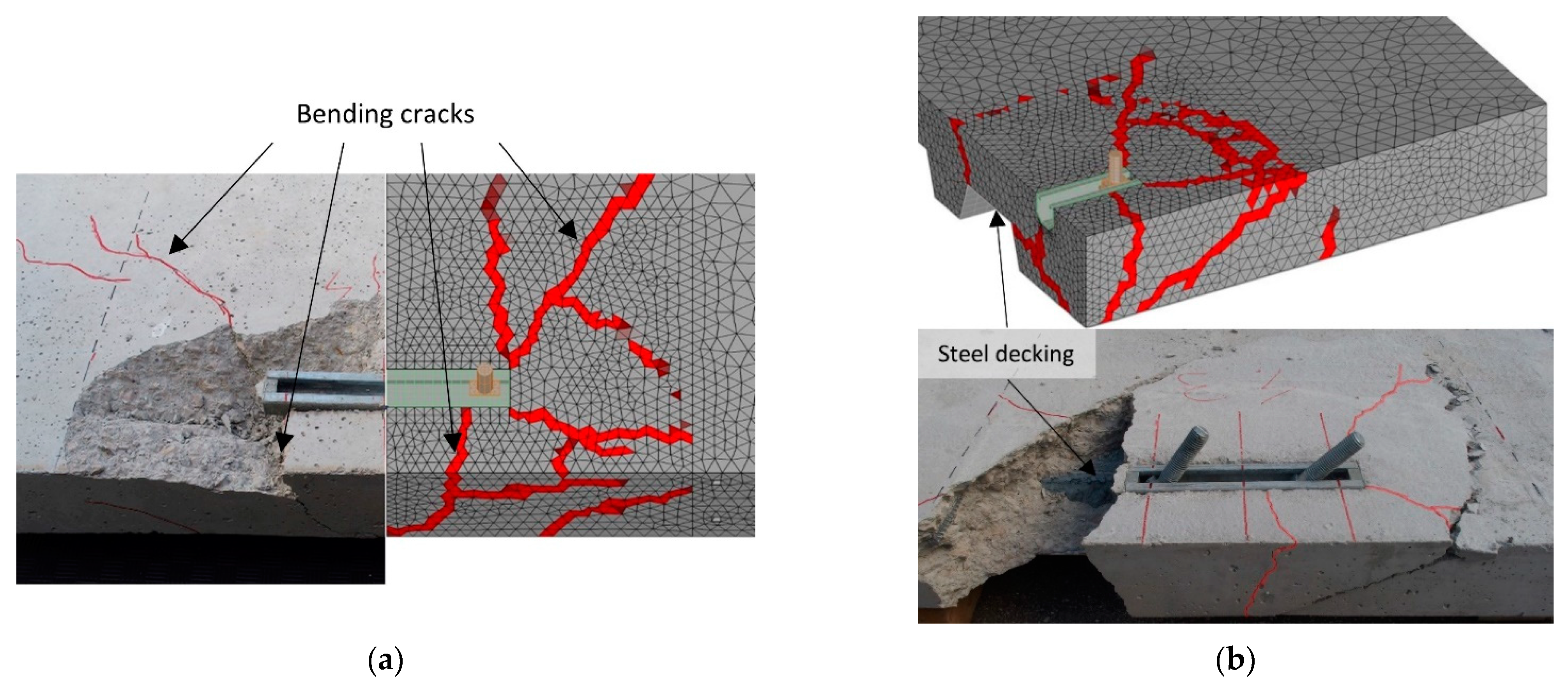
3.1. Validation of the Numerical Model
3.2. Definition of the Support and Boundary Conditions
4. Numerical Parametric Study
5. Numerical Results and Evaluation
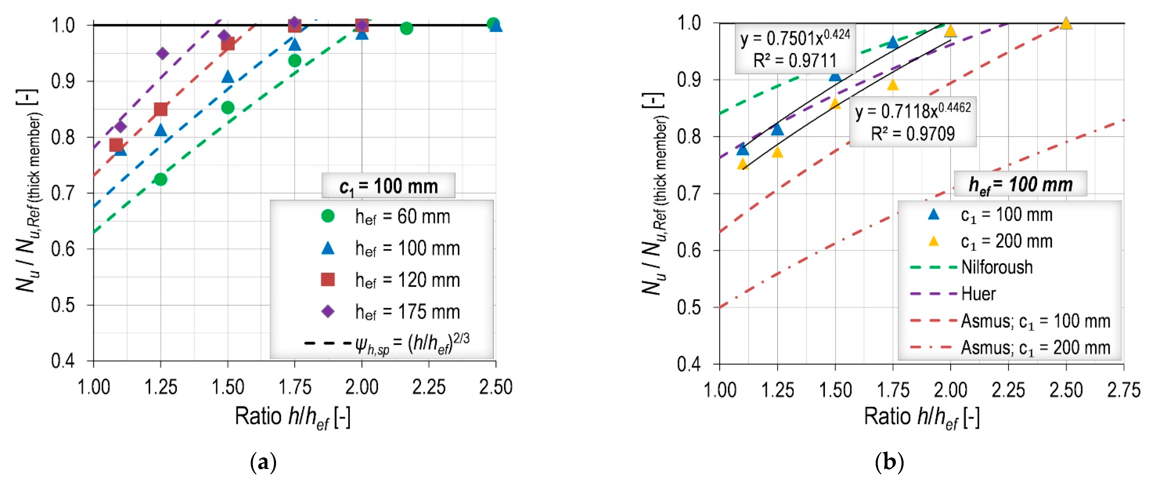
5.1. Influence of Member Thickness
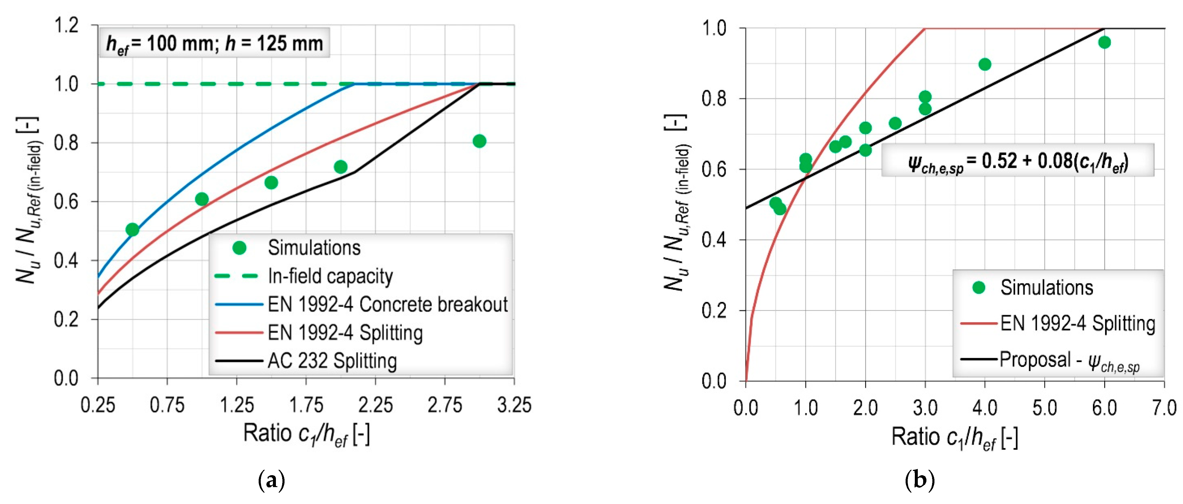
5.2. Influence of Edge Distance
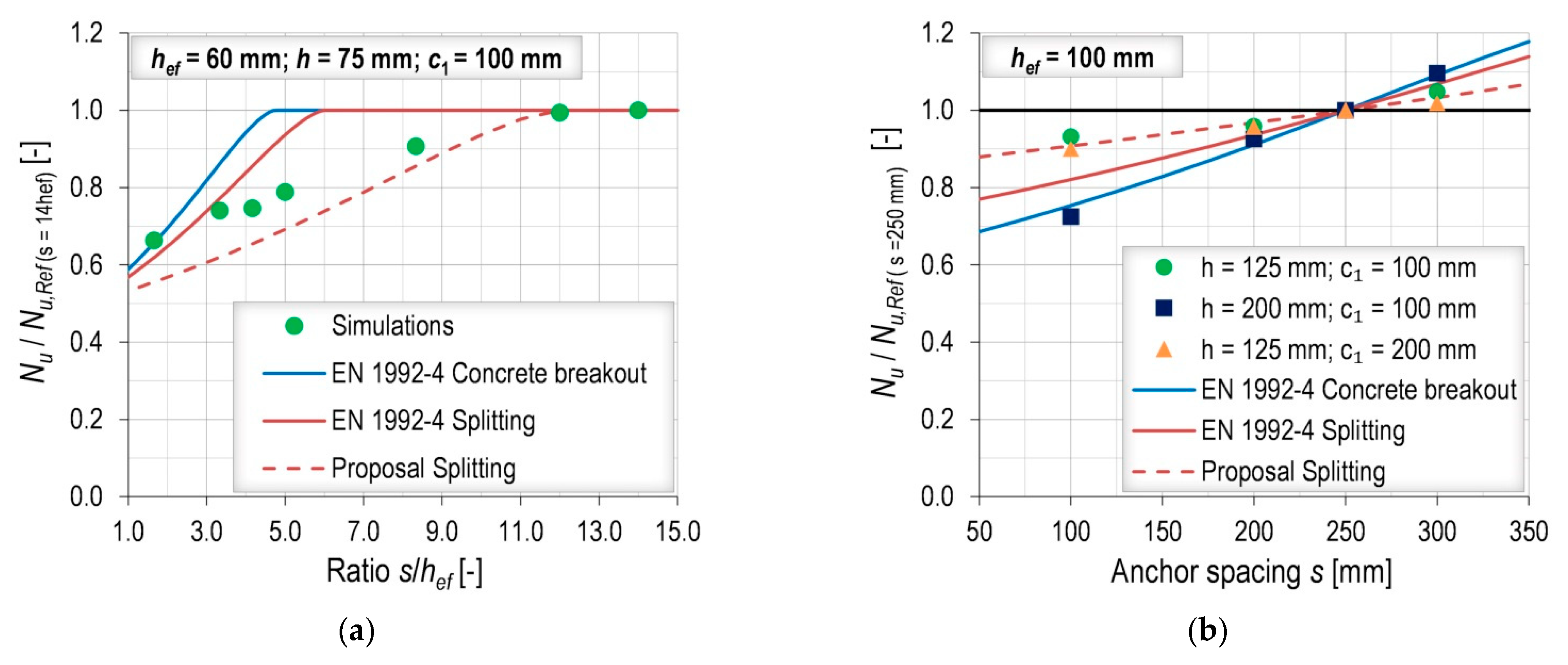
5.3. Influence of Anchor Spacing
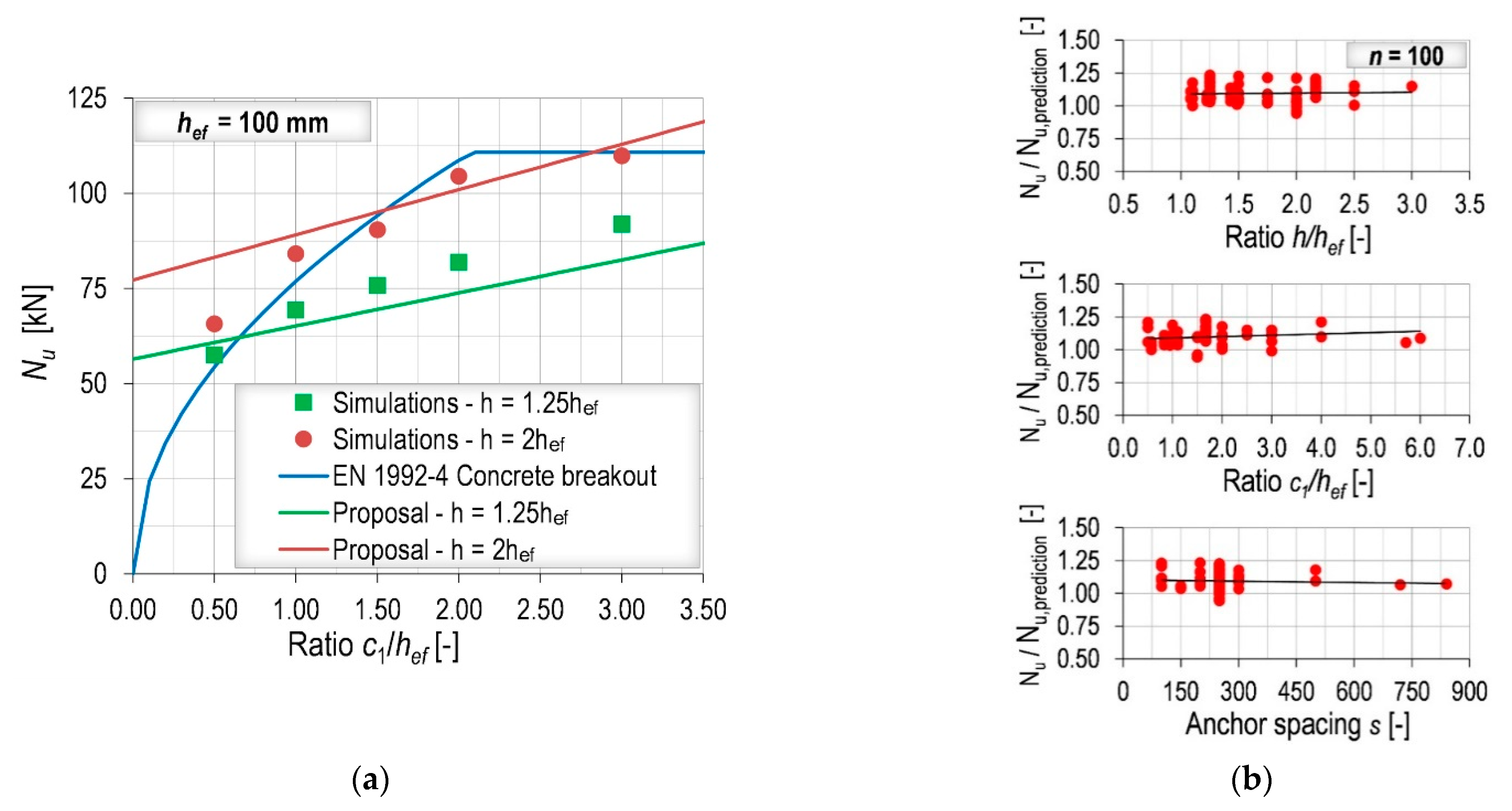
5.4. Modifications of the Current Design Model for Concrete Splitting of EN 1992-4
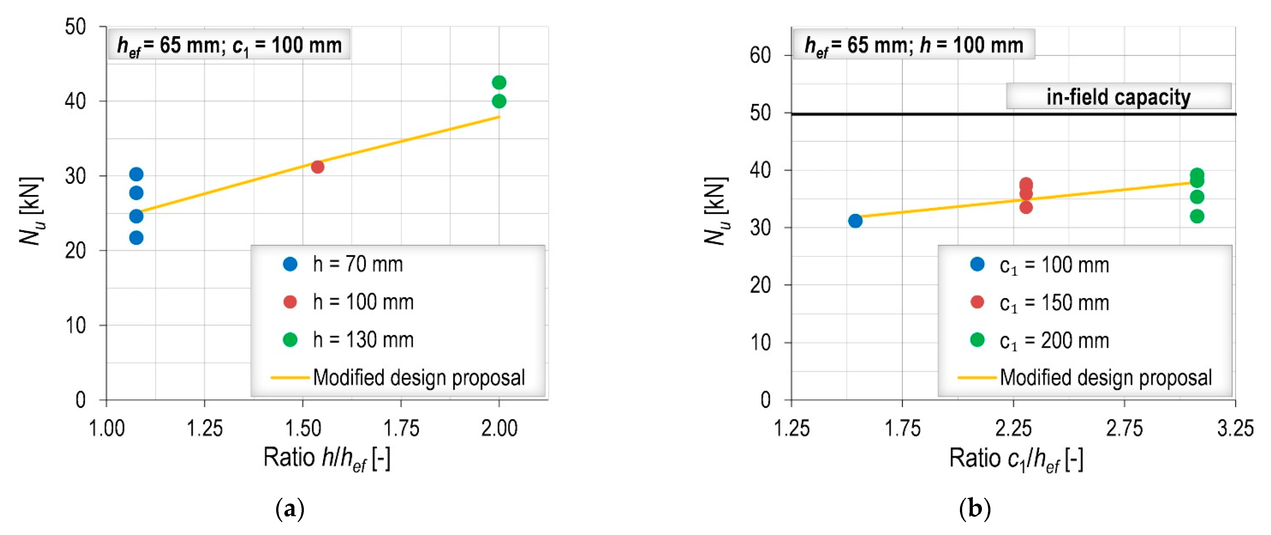
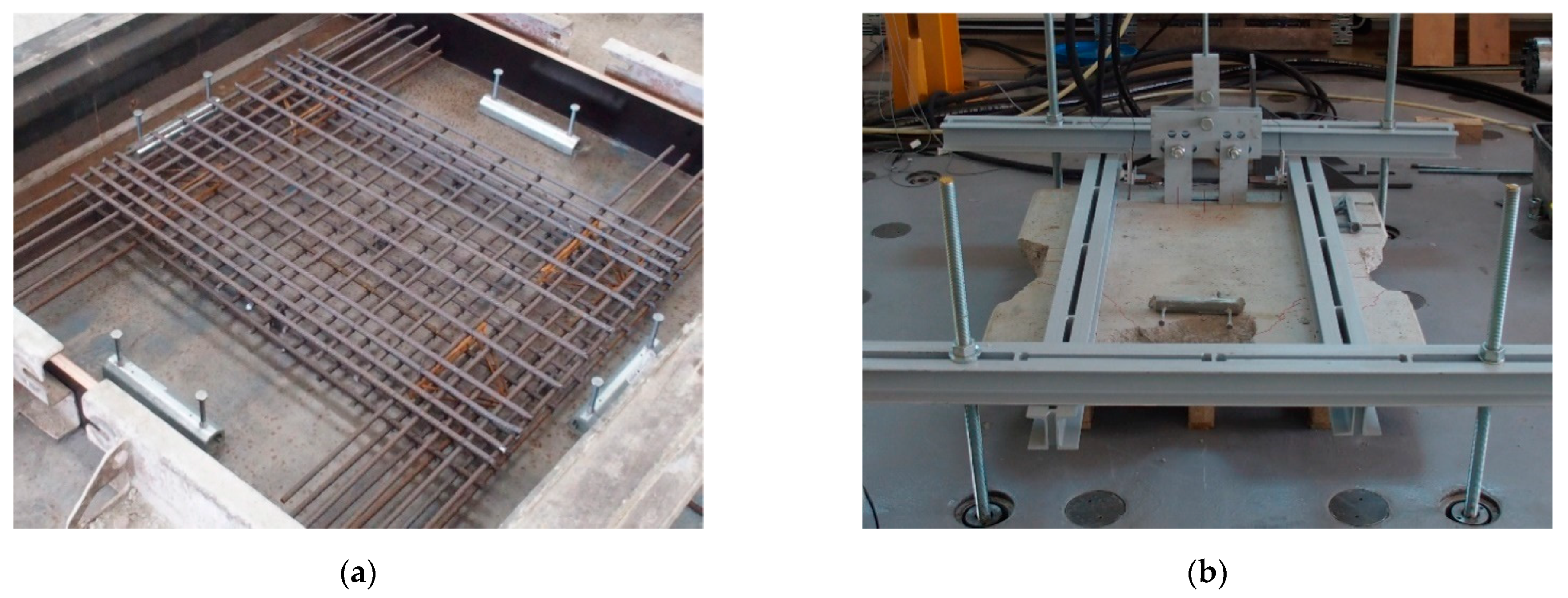
6. Experimental Results
7. Conclusions
- The 3D FE code employed in the numerical investigation, which is based on the microplane model for concrete, the smeared crack approach and the crack band regularization method, was able to replicate the experimentally obtained ultimate capacities and failure modes. However, the load-bearing behavior in numerical simulations was stiffer than in experiments resulting in smaller displacements at the ultimate capacity. The possible reason could be the local crushing of concrete around the anchor head that cannot be properly accounted for in macroscopic analyses.
- The influence of member thickness should be considered in the design model for concrete splitting. It was found that the existing factor of EN 1992-4 is relatively accurate at predicting the influence of member thickness. An improvement for the modification factor to take the slab thickness into account is proposed. The value hmin (chosen by the manufacturer for qualification testing) should be replaced by the embedment depth hef (physical dimension) together with a different calibrating factor of 1.15. The experimental results also showed that the influence of member thickness is present for anchor channels without edge influence, which is consistent with the findings of Nilforoush [8] for headed studs, although with slightly different results.
- Currently, the characteristic edge distance for splitting is set to ccr,sp = 3hef. According to the numerical and experimental results, a larger value is required to attain the capacity without edge influence, especially when the concrete member is relatively thin. In addition, it was found that the influence of edge distance can be well approximated by a linear function that yields to the limit value for c1 = 6hef.
- The numerical results indicated that the proportion between the characteristic edge distance and characteristic anchor spacing should be scr,sp = 2ccr,sp = 12hef.
- The doubling of the critical edge and spacing distances may seem excessive but, together with the other proposed modifications, results in the splitting failure only being decisive for small slab thicknesses compared to the concrete breakout failure.
- The experimental results showed that the modified design model for splitting is able to accurately predict the tensile capacity of anchor channels in thin slabs. This is very important as a basis for future work on the design of anchor channels in composite slabs, where an additional reduction factor should be applied to account for complex geometry of the concrete above the metal deck.
- In the prospective harmonization of the US and European verifications, the authors recommend keeping the two verifications for splitting and concrete breakout separately as per EN 1992-4, accordingly modifying the splitting verification, as this approach was proven to provide an overall excellent accuracy.
Outlook
- The influence of corners on the capacity of anchor channels in thin members should be clarified.
- The influence of reinforcement should be studied in detail since the presence of adequate reinforcement is considered to be a condition when the splitting verification can be omitted.
- Further numerical and experimental investigations for anchor channels without edge influence are required to determine how to consider the influence of member thickness in the verification for concrete breakout.
Author Contributions
Funding
Data Availability Statement
Acknowledgments
Conflicts of Interest
Appendix A

| c1 [mm] | hef [mm] | h [mm] | s [mm] | Nu [kN] | Nu,CB1 [kN] | Nu,proposal2 [kN] | Nu/Nu,decisive3 [−] |
|---|---|---|---|---|---|---|---|
| 100 | 60 | 75 | 250 | 33.46 | 40.20 | 28.47 | 1.18 |
| 100 | 60 | 90 | 250 | 39.38 | 40.20 | 32.15 | 1.22 |
| 100 | 60 | 105 | 250 | 43.25 | 40.20 | 35.63 | 1.21 |
| 100 | 60 | 130 | 250 | 45.91 | 40.20 | 41.09 | 1.14 |
| 100 | 60 | 150 | 250 | 46.29 | 40.20 | 42.67 | 1.15 |
| 100 | 60 | 180 | 250 | 46.16 | 40.20 | 42.67 | 1.15 |
| 100 | 100 | 110 | 250 | 66.39 | 76.87 | 59.82 | 1.11 |
| 100 | 100 | 125 | 250 | 69.39 | 76.87 | 65.15 | 1.07 |
| 100 | 100 | 150 | 250 | 77.51 | 76.87 | 73.56 | 1.05 |
| 100 | 100 | 175 | 250 | 82.40 | 76.87 | 81.53 | 1.07 |
| 100 | 100 | 200 | 250 | 84.09 | 76.87 | 89.12 | 1.09 |
| 100 | 100 | 250 | 250 | 85.26 | 76.87 | 93.03 | 1.11 |
| 200 | 100 | 110 | 250 | 79.71 | 108.72 | 67.80 | 1.18 |
| 200 | 100 | 125 | 250 | 81.87 | 108.72 | 73.83 | 1.11 |
| 200 | 100 | 150 | 250 | 90.93 | 108.72 | 83.37 | 1.09 |
| 200 | 100 | 175 | 250 | 94.40 | 108.72 | 92.40 | 1.02 |
| 200 | 100 | 200 | 250 | 104.47 | 108.72 | 101.00 | 1.03 |
| 200 | 100 | 250 | 250 | 105.80 | 108.72 | 105.43 | 1.00 |
| 100 | 120 | 130 | 250 | 80.20 | 93.66 | 76.13 | 1.05 |
| 100 | 120 | 150 | 250 | 86.72 | 93.66 | 83.75 | 1.04 |
| 100 | 120 | 180 | 250 | 98.72 | 93.66 | 94.58 | 1.05 |
| 100 | 120 | 210 | 250 | 101.96 | 93.66 | 104.81 | 1.09 |
| 100 | 120 | 240 | 250 | 102.00 | 93.66 | 114.57 | 1.09 |
| 100 | 175 | 193 | 250 | 129.21 | 153.06 | 129.24 | 1.00 |
| 100 | 175 | 220 | 250 | 149.80 | 153.06 | 141.27 | 1.06 |
| 100 | 175 | 260 | 250 | 154.79 | 153.06 | 157.91 | 1.01 |
| 100 | 175 | 306 | 250 | 158.54 | 153.06 | 176.03 | 1.04 |
| 100 | 175 | 350 | 250 | 157.74 | 153.06 | 181.85 | 1.03 |
| c1 [mm] | hef [mm] | h [mm] | s [mm] | Nu [kN] | Nu,CB1 [kN] | Nu,proposal2 [kN] | Nu/Nu,decisive3 [−] |
|---|---|---|---|---|---|---|---|
| 60 | 60 | 75 | 250 | 31.04 | 31.14 | 26.15 | 1.19 |
| 100 | 60 | 75 | 250 | 33.46 | 40.20 | 28.47 | 1.18 |
| 150 | 60 | 75 | 250 | 36.07 | 47.90 | 31.38 | 1.15 |
| 180 | 60 | 75 | 250 | 38.06 | 47.90 | 33.12 | 1.15 |
| 240 | 60 | 75 | 250 | 44.29 | 47.90 | 36.61 | 1.21 |
| 360 | 60 | 75 | 250 | 47.38 | 47.90 | 43.58 | 1.09 |
| ∞ | 60 | 75 | 250 | 49.37 | 47.90 | / | 1.03 |
| 60 | 60 | 130 | 250 | 36.85 | 31.14 | 37.73 | 1.18 |
| 100 | 60 | 130 | 250 | 45.91 | 40.20 | 41.09 | 1.14 |
| 150 | 60 | 130 | 250 | 50.33 | 47.90 | 45.28 | 1.11 |
| 180 | 60 | 130 | 250 | 50.78 | 47.90 | 47.79 | 1.06 |
| 240 | 60 | 130 | 250 | 52.53 | 47.90 | 52.82 | 1.10 |
| ∞ | 60 | 130 | 250 | 53.88 | 47.90 | / | 1.12 |
| 50 | 100 | 125 | 250 | 57.55 | 54.36 | 60.80 | 1.06 |
| 100 | 100 | 125 | 250 | 69.39 | 76.87 | 65.15 | 1.07 |
| 150 | 100 | 125 | 250 | 75.83 | 94.15 | 69.49 | 1.09 |
| 200 | 100 | 125 | 250 | 81.87 | 108.72 | 73.83 | 1.11 |
| 300 | 100 | 125 | 250 | 91.89 | 110.81 | 82.52 | 1.11 |
| ∞ | 100 | 125 | 250 | 114.12 | 110.81 | / | 1.03 |
| 50 | 100 | 150 | 250 | 63.43 | 54.36 | 68.66 | 1.17 |
| 100 | 100 | 150 | 250 | 77.51 | 76.87 | 73.56 | 1.05 |
| 150 | 100 | 150 | 250 | 86.29 | 94.15 | 78.47 | 1.10 |
| 200 | 100 | 150 | 250 | 90.93 | 108.72 | 83.37 | 1.09 |
| ∞ | 100 | 150 | 250 | 114.12 | 110.81 | / | 1.03 |
| 50 | 100 | 200 | 250 | 65.74 | 54.36 | 83.18 | 1.21 |
| 100 | 100 | 200 | 250 | 84.09 | 76.87 | 89.12 | 1.09 |
| 150 | 100 | 200 | 250 | 90.43 | 94.15 | 95.06 | 0.96 |
| 200 | 100 | 200 | 250 | 104.47 | 108.72 | 101.00 | 1.03 |
| 300 | 100 | 200 | 250 | 109.84 | 110.81 | 112.88 | 0.99 |
| ∞ | 100 | 200 | 250 | 123.06 | 110.81 | / | 1.11 |
| 100 | 175 | 193 | 250 | 129.21 | 153.06 | 129.24 | 1.00 |
| 350 | 175 | 193 | 250 | 173.13 | 250.95 | 155.34 | 1.11 |
| ∞ | 175 | 193 | 250 | 264.75 | 250.95 | / | 1.06 |
| 100 | 175 | 350 | 250 | 157.74 | 153.06 | 181.85 | 1.03 |
| 262 | 175 | 350 | 250 | 193.99 | 247.74 | 205.66 | 0.94 |
| ∞ | 175 | 350 | 250 | 255.28 | 250.95 | / | 1.02 |
| c1 [mm] | hef [mm] | h [mm] | s [mm] | Nu [kN] | Nu,CB1
[kN] | Nu,proposal2 [kN] | Nu/Nu,decisive3 [−] |
|---|---|---|---|---|---|---|---|
| 100 | 60 | 75 | 100 | 29.72 | 27.51 | 24.17 | 1.23 |
| 100 | 60 | 75 | 200 | 33.20 | 36.06 | 26.95 | 1.23 |
| 100 | 60 | 75 | 250 | 33.46 | 40.20 | 28.47 | 1.18 |
| 100 | 60 | 75 | 300 | 35.34 | 41.86 | 30.09 | 1.17 |
| 100 | 60 | 75 | 500 | 40.66 | 41.86 | 37.21 | 1.09 |
| 100 | 60 | 75 | 720 | 44.56 | 41.86 | 43.49 | 1.06 |
| 100 | 60 | 75 | 840 | 44.83 | 41.86 | 43.49 | 1.07 |
| 100 | 60 | 130 | 100 | 33.20 | 27.51 | 34.88 | 1.21 |
| 100 | 60 | 130 | 200 | 41.98 | 36.06 | 38.89 | 1.16 |
| 100 | 60 | 130 | 250 | 45.91 | 40.20 | 41.09 | 1.14 |
| 100 | 60 | 130 | 300 | 47.17 | 41.86 | 43.41 | 1.13 |
| 100 | 60 | 130 | 500 | 49.29 | 41.86 | 53.69 | 1.18 |
| 100 | 100 | 125 | 100 | 64.63 | 57.89 | 59.13 | 1.12 |
| 100 | 100 | 125 | 200 | 66.53 | 70.04 | 63.06 | 1.05 |
| 100 | 100 | 125 | 250 | 69.39 | 76.87 | 65.15 | 1.07 |
| 100 | 100 | 125 | 300 | 72.72 | 83.90 | 67.31 | 1.08 |
| 100 | 100 | 200 | 100 | 60.90 | 57.89 | 80.89 | 1.05 |
| 100 | 100 | 200 | 200 | 77.84 | 70.04 | 86.27 | 1.11 |
| 100 | 100 | 200 | 250 | 84.09 | 76.87 | 89.12 | 1.09 |
| 100 | 100 | 200 | 300 | 92.13 | 83.90 | 92.08 | 1.10 |
| 200 | 100 | 125 | 100 | 73.66 | 81.88 | 67.02 | 1.10 |
| 200 | 100 | 125 | 200 | 78.37 | 99.05 | 71.47 | 1.10 |
| 200 | 100 | 125 | 250 | 81.87 | 108.72 | 73.83 | 1.11 |
| 200 | 100 | 125 | 300 | 83.40 | 118.66 | 76.29 | 1.09 |
| 100 | 91 | 130 | 150 | 59.34 | 57.32 | 58.43 | 1.04 |
| 100 | 91 | 130 | 200 | 64.51 | 63.43 | 60.55 | 1.07 |
| 100 | 91 | 130 | 250 | 67.98 | 69.95 | 62.76 | 1.08 |
| 100 | 91 | 130 | 300 | 73.96 | 76.52 | 65.06 | 1.14 |
| 100 | 106 | 130 | 150 | 68.21 | 68.09 | 65.51 | 1.04 |
| 100 | 106 | 130 | 200 | 73.19 | 74.65 | 67.53 | 1.08 |
| 100 | 106 | 130 | 250 | 73.45 | 81.70 | 69.63 | 1.05 |
| 100 | 106 | 130 | 300 | 74.28 | 89.01 | 71.81 | 1.03 |
| 100 | 120 | 130 | 150 | 76.13 | 79.01 | 72.15 | 1.06 |
| 100 | 120 | 130 | 200 | 78.46 | 86.06 | 74.11 | 1.06 |
| 100 | 120 | 130 | 250 | 80.20 | 93.66 | 76.13 | 1.05 |
| 100 | 120 | 130 | 300 | 86.79 | 101.64 | 78.22 | 1.11 |
References
- ACI 318. Building Code Requirements for Structural Concrete (ACI 318-14) and Commentary (ACI 318R-14); American Concrete Institute: Farmington Hills, MI, USA, 2014. [Google Scholar]
- AC232. Acceptance Criteria for Anchor Channels in Concrete Elements; ICC-ES: Whittier, CA, USA, 2019. [Google Scholar]
- EN 1992-4. Eurocode 2—Design of Concrete Structures—Part 4: Design of Fastenings for Use in Concrete (EN 1992-4:2018); European Committee for Standardization (CEN): Brussels, Belgium, 2018. [Google Scholar]
- Asmus, J. Bemessung von Zugbeanspruchten Befestigungen bei der Versagensart Spalten des Betons (Design of Tension Loaded Anchorages for the Splitting Failure Mode). Ph.D. Thesis, University of Stuttgart, Stuttgart, Germany, 1999. (In German). [Google Scholar]
- Asmus, J.; Eligehausen, R. Design Method for Splitting Failure Mode of Fastenings. In Proceedings of the 2nd International Symposium on Connections between Steel and Concrete, Stuttgart, Germany, 4–7 September 2007. [Google Scholar]
- Hüer, T. Tragverhalten von Randnahen Zugbeanspruchten Befestigungen bei der Versagensart “Spalten des Betons” (Behavior of Tension Loaded Fasteners near the Edge for the Concrete Splitting Failure Mode). Ph.D. Thesis, University of Stuttgart, Stuttgart, Germany, 2014. (In German). [Google Scholar]
- Fuchs, W.; Eligehausen, R.; Breen, J.E. Concrete capacity design (CCD) approach for fastenings to concrete. ACI Struct. J. 1995, 2, 73–94. [Google Scholar]
- Nilforoush, R. Numerical and Experimental Evaluations of Load-Carrying Capacity of Cast-in-Place Headed Anchors and Post-Installed Adhesive Anchors. Ph.D. Thesis, University of Lulea, Lulea, Sweden, 2017. [Google Scholar]
- Grosser, R.; Dimitrova, T.; Winkler, B. Anchor channels with short embedment depth used in composite slab construction. In Proceedings of the 3rd International Symposium on Connections between Steel and Concrete, Stuttgart, Germany, 27–29 September 2017. [Google Scholar]
- Mahrenholtz, C.; Sharma, A. Load Capacity of Shallow Embedded Anchor Channels. CivilEng 2020, 1, 243–252. [Google Scholar] [CrossRef]
- EAD 330008-03-0601. Anchor Channels, European Assessment Document; OJEU 2018/C; EOTA: Brussels, Belgium, 2018. [Google Scholar]
- Ožbolt, J.; Li, Y.; Kožar, I. Microplane model for concrete with relaxed kinematic constraints. Int. J. Solids Struct. 2001, 38, 2683–2711. [Google Scholar] [CrossRef]
- Bažant, Z.P.; Oh, B. Crack band theory for fracture of concrete. Mater. Struct. 1983, 16, 155–177. [Google Scholar] [CrossRef] [Green Version]
- Ožbolt, J.; Gambarelli, S. Microplane model with relaxed kinematic constraint in the framework of micro polar Cosserat continuum. Eng. Fract. Mech. 2018, 199, 476–488. [Google Scholar] [CrossRef]
- Jirásek, M.; Bauer, M. Numerical aspects of the crack band approach. Comput. Struct. 2012, 110, 60–78. [Google Scholar] [CrossRef]
- Bogdanić, A.; Casucci, D.; Ožbolt, J. Numerical and Experimental Investigation of Anchor Channels Subjected to Shear Load in Composite Slabs with Profiled Steel Decking. Eng. Struct. 2021, 240, 112347. [Google Scholar] [CrossRef]
- FEMAP®; Version 11.2.2; Siemens PLM Software: Plano, TX, USA, 2015.
- ETA-11/0006. Hilti Anchor Channels (HAC) with Channel Bolts (HBC); DIBt: Berlin, Germany, 2016. [Google Scholar]
- Fichtner, S. Implementierung Einer Kontaktschicht Mit Reibeigenschaften für Kleine Verformungen in das Programm MASA; Prüfbericht Nr. HT 141/01-04/8; Institute of Construction Materials, University of Stuttgart: Stuttgart, Germany, 2005. [Google Scholar]
- CEB-FIP Model Code 1990. Comité Euro-International du Béton and Fédération Internationale de la Précontrainte; Tomas Telford: London, UK, 1993. [Google Scholar]
- Jebara, K.; Ožbolt, J.; Hoffman, J. Pryout failure of single headed stud anchor: 3D numerical FE analysis. Mater. Struct. 2016, 49, 4551–4563. [Google Scholar] [CrossRef]


| Author | Characteristic Member Thickness | Modification Factor |
|---|---|---|
| Asmus | ||
| Hüer | ||
| Nilforoush | 1 |
| Strength Class | CEM II/B-M (S-LL) 42.5 N [kg/m3] | Aggregate (Dmax = 16 mm) [kg/m3] | Water [kg/m3] |
|---|---|---|---|
| C16/20 | 290 | 1870 | 208 (w/c = 0.72) |
| Slab Type | c1 [mm] | hef [mm] | h [mm] | Nu,m [kN] | σ [kN] | CoV [%] | Nu,sim [kN] | Nu,sim/Nu,m [−] |
|---|---|---|---|---|---|---|---|---|
| plain | 100 | 106 | 130 | 79.00 | 0.90 | 1.14 | 74.48 | 0.94 |
| composite | 100 | 106 | 130 | 52.22 | 2.95 | 5.66 | 51.08 | 0.98 |
| c1 [mm] | hef [mm] | h [mm] | Nu,m [kN] | n [−] | σ [kN] | CoV [%] | Nu,sim [kN] | Nu,sim/Nu,m [−] |
|---|---|---|---|---|---|---|---|---|
| 100 | 65 | 70 | 28.89 | 4 | 4.10 | 14.20 | 31.46 | 1.09 |
| 100 | 65 | 130 | 45.72 | 2 | 1.97 | 4.31 | 45.16 | 0.99 |
| c1 [mm] | hef [mm] | h/hef [−] |
|---|---|---|
| 100 | 100, 120, 175 | 1.10 |
| 100 | 60, 100, 120, 175 | 1.25 |
| 100 | 60, 100, 120, 175 | 1.50 |
| 100 | 60, 100, 120, 175 | 1.75 |
| 100 | 60, 100, 120, 175 | 2.00 |
| 100 | 60, 100 | 2.50 |
| 100 | 60 | 3.00 |
| 200 | 100 | 1.10–2.50 |
| c1/hef [−] | hef [mm] | h [mm] |
|---|---|---|
| 1.00, 1.67, 2.50, 3.00, 4.00, 6.00, in-field | 60 | 75 |
| 1.00, 1.67, 2.50, 3.00, 4.00, in-field | 60 | 130 |
| 0.50, 1.00, 1.50, 2.00, 3.00, in-field | 100 | 125 |
| 0.50, 1.00, 1.50, 2.00, in-field | 100 | 150 |
| 0.50, 1.00, 1.50, 2.00, 3.00, in-field | 100 | 200 |
| 0.50, 2.00, in-field | 175 | 193 |
| 0.50, 1.50, in-field | 175 | 350 |
| s [mm] | c1 [mm] | hef [mm] | h [mm] |
|---|---|---|---|
| 150, 200, 250, 300 | 100 | 91 | 130 |
| 150, 200, 250, 300 | 100 | 106 | 130 |
| 150, 200, 250, 300 | 100 | 120 | 130 |
| 100, 200, 250, 300, 500, 720, 840 | 100 | 60 | 75 |
| 100, 200, 250, 300, 500 | 100 | 60 | 130 |
| 100, 200, 250, 300 | 100 | 100 | 125 |
| 100, 200, 250, 300 | 100 | 100 | 200 |
| 100, 200, 250, 300 | 200 | 100 | 125 |
| h [mm] | Nu,m [kN] | Nu,m/Nu,m,Ref (h = 130 mm) [−] | σ [kN] | CoV [%] | Nu,code [kN] | Nu,Grosser [kN] | (h/2hef)0.25 [−] |
|---|---|---|---|---|---|---|---|
| 70 | 40.51 | 0.71 | 1.26 | 2.81 | 24.27 | 50.37 | 0.86 |
| 100 | 49.71 | 0.87 | 1.63 | 2.96 | 24.27 | 50.37 | 0.94 |
| 130 | 57.44 | 1.00 | 4.69 | 7.38 | 24.27 | 50.37 | 1.00 |
| c1 [mm] | hef [mm] | h [mm] | Nu,m [kN] | ntest [−] | σ [kN] | CoV [%] | Nu,proposal [kN] | Nu,m/Nu,proposal [kN] |
|---|---|---|---|---|---|---|---|---|
| 100 | 65 | 70 | 26.08 | 4 | 4.10 | 14.20 | 25.09 | 1.04 |
| 100 | 65 | 100 | 31.20 | 1 | - | - | 31.82 | 0.98 |
| 100 | 65 | 130 | 41.27 | 2 | 1.97 | 4.31 | 37.90 | 1.09 |
| 150 | 65 | 100 | 36.06 | 4 | 2.04 | 5.10 | 34.86 | 1.03 |
| 200 | 65 | 100 | 36.19 | 4 | 3.56 | 8.89 | 37.91 | 0.95 |
Publisher’s Note: MDPI stays neutral with regard to jurisdictional claims in published maps and institutional affiliations. |
© 2021 by the authors. Licensee MDPI, Basel, Switzerland. This article is an open access article distributed under the terms and conditions of the Creative Commons Attribution (CC BY) license (https://creativecommons.org/licenses/by/4.0/).
Share and Cite
Bogdanić, A.; Casucci, D.; Ožbolt, J. Numerical and Experimental Investigation on Concrete Splitting Failure of Anchor Channels. CivilEng 2021, 2, 502-522. https://doi.org/10.3390/civileng2020028
Bogdanić A, Casucci D, Ožbolt J. Numerical and Experimental Investigation on Concrete Splitting Failure of Anchor Channels. CivilEng. 2021; 2(2):502-522. https://doi.org/10.3390/civileng2020028
Chicago/Turabian StyleBogdanić, Anton, Daniele Casucci, and Joško Ožbolt. 2021. "Numerical and Experimental Investigation on Concrete Splitting Failure of Anchor Channels" CivilEng 2, no. 2: 502-522. https://doi.org/10.3390/civileng2020028
APA StyleBogdanić, A., Casucci, D., & Ožbolt, J. (2021). Numerical and Experimental Investigation on Concrete Splitting Failure of Anchor Channels. CivilEng, 2(2), 502-522. https://doi.org/10.3390/civileng2020028