
Finite Element Analysis of Heavy Duty Riveted Steel Grating Bridge Deck

Abstract
:1. Introduction
2. Finite Element Modeling
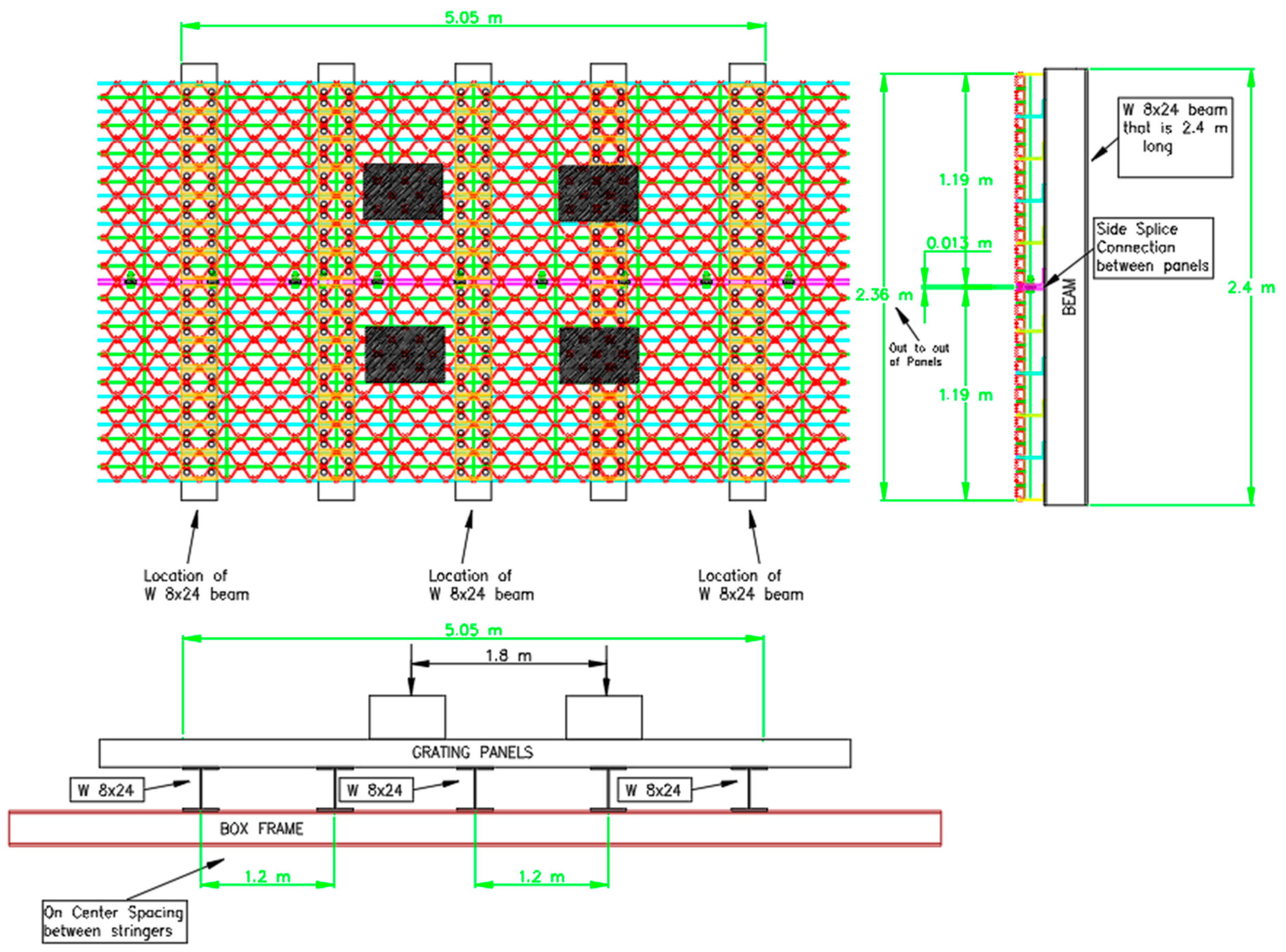
2.1. Building the Model: A Heavy Duty Riveted Grating
2.2. Elastic Properties, Boundary Conditions and Loading
2.3. Results of Finite-Element Analysis
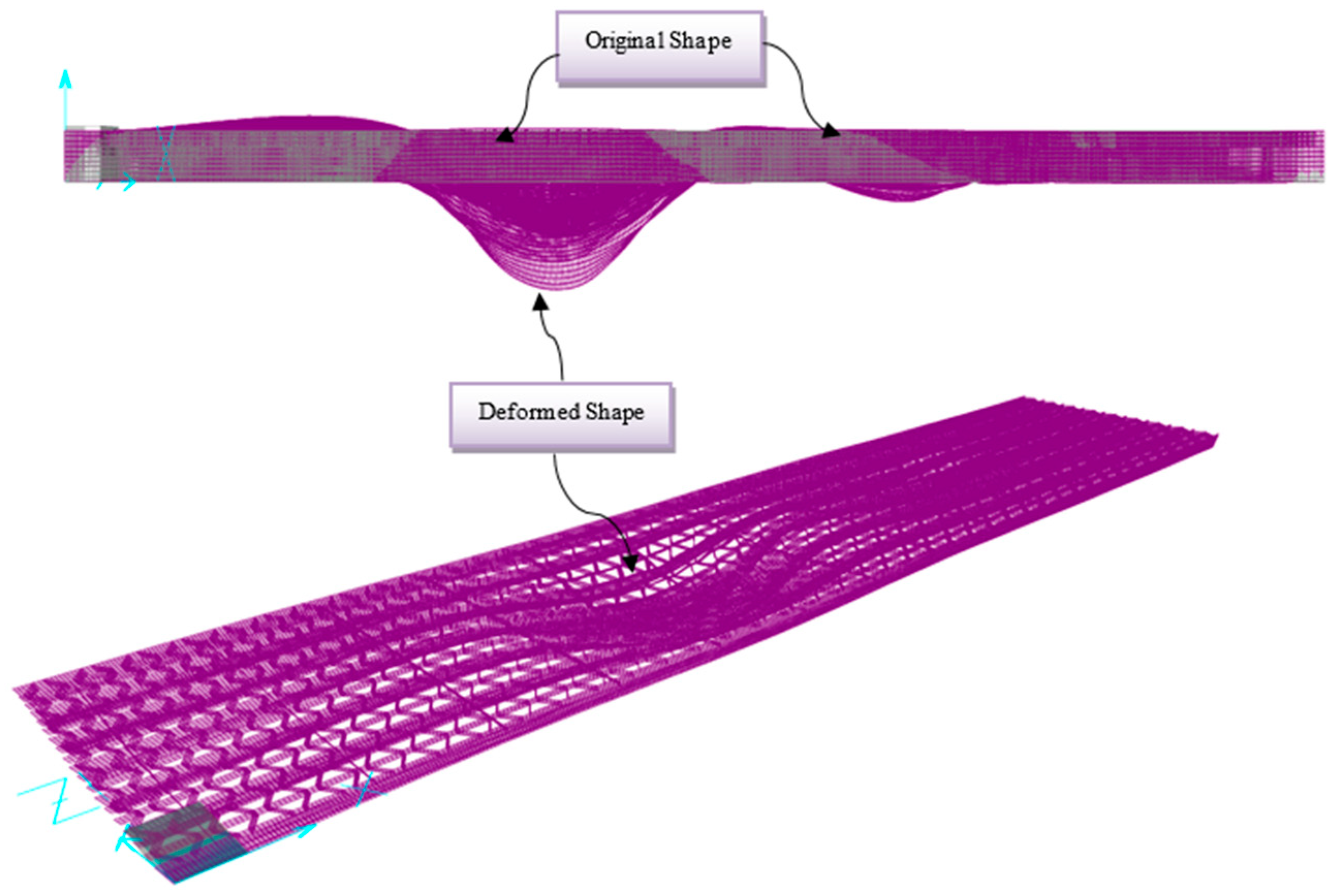
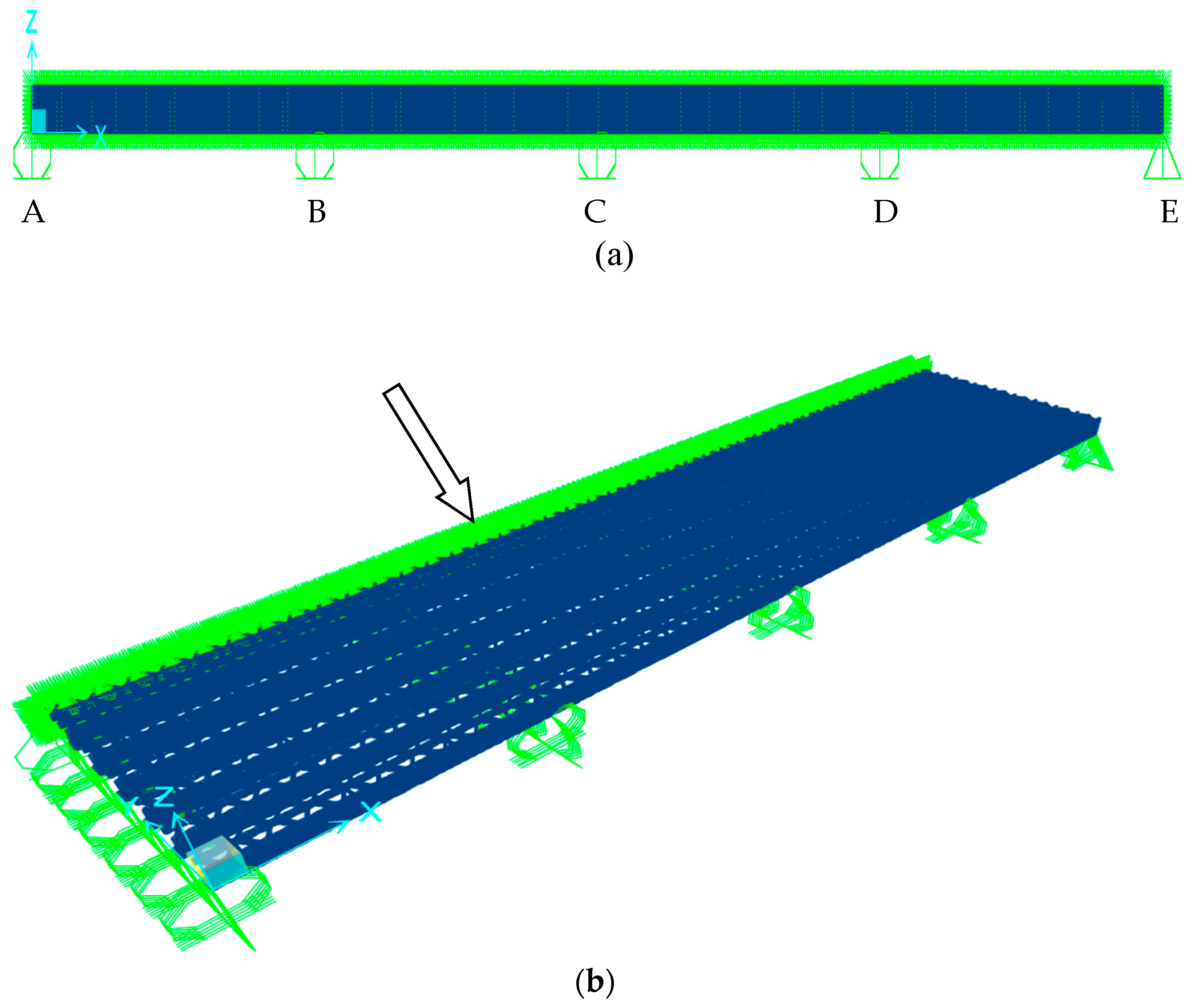
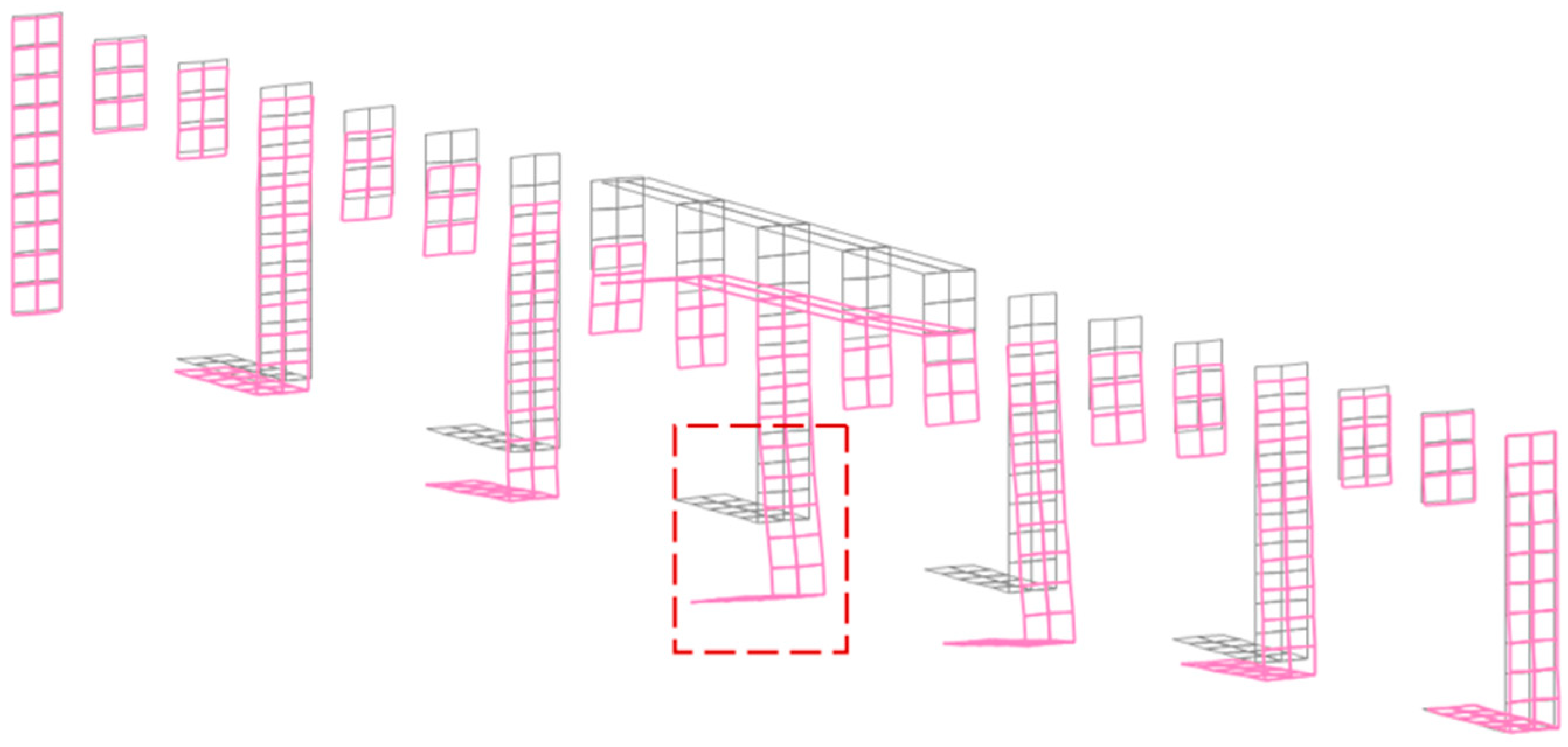
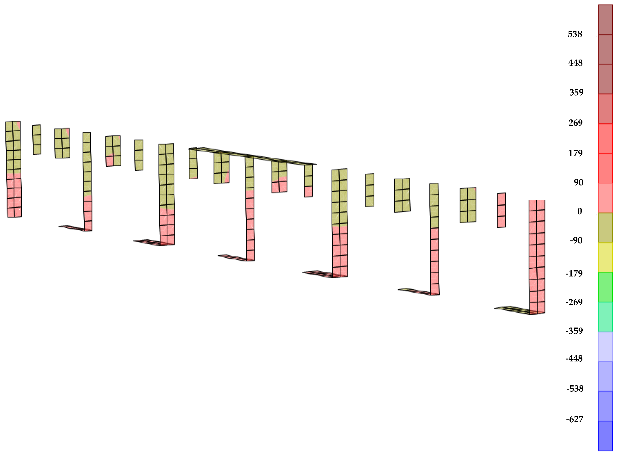
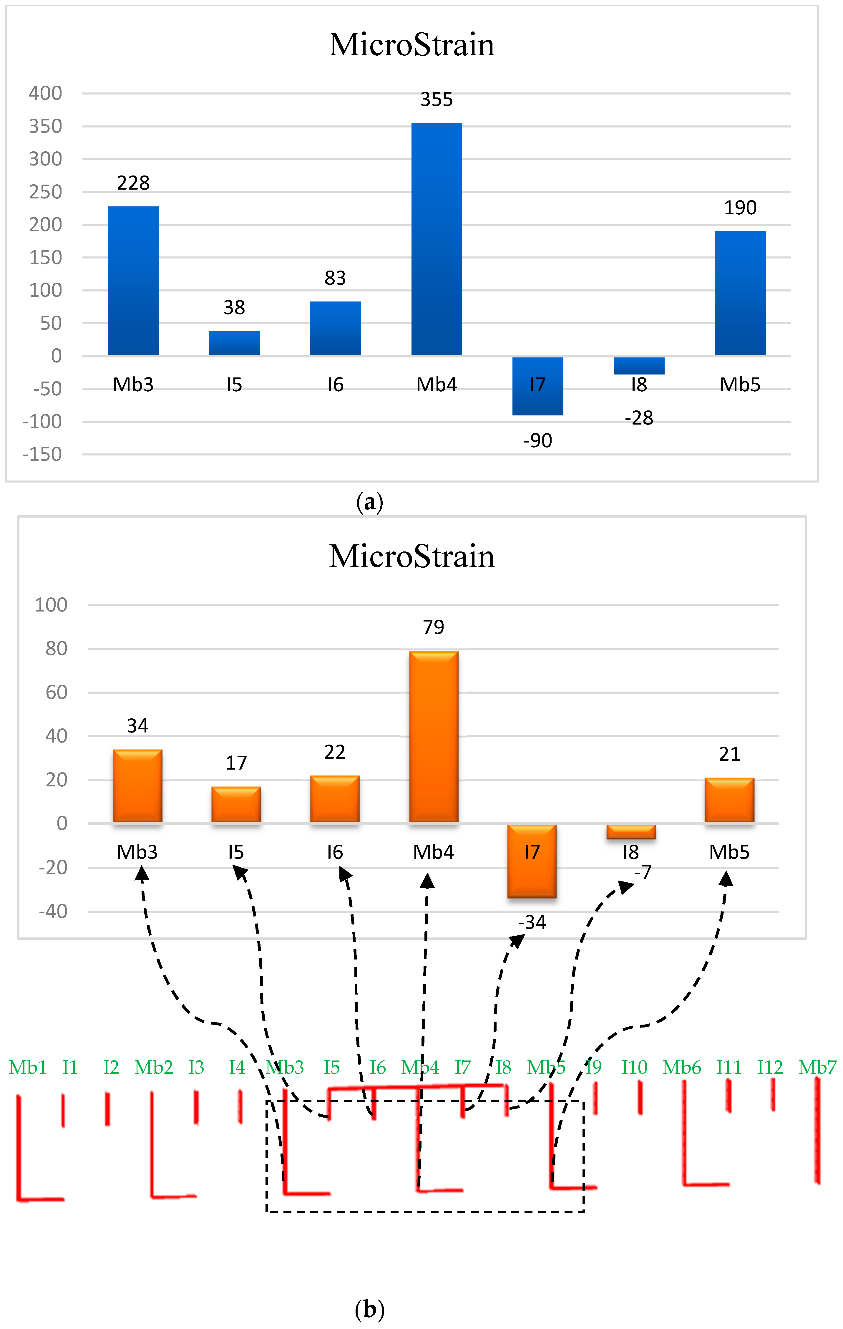
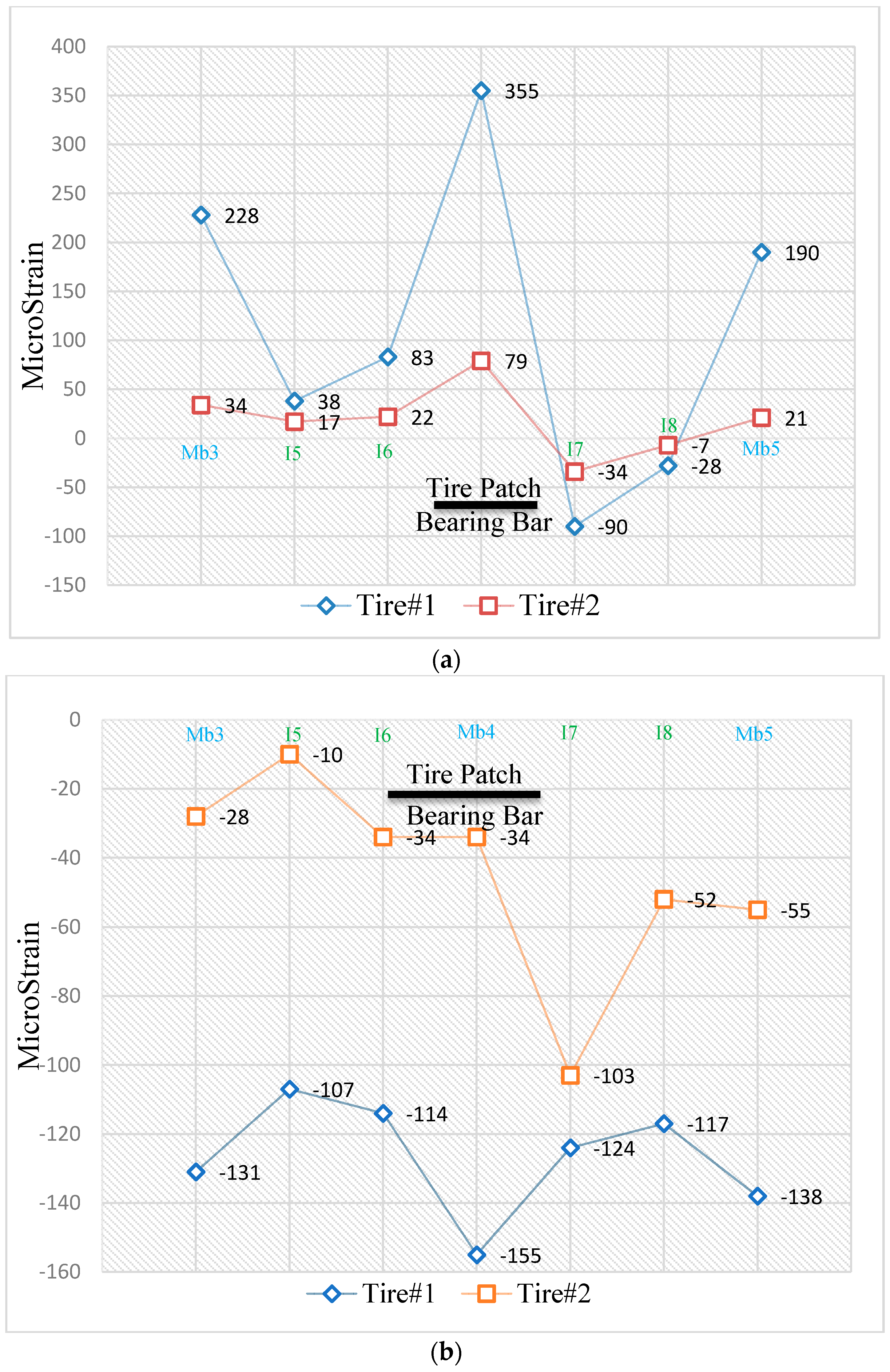
2.3.1. Static Results of the Entire Panel Model
Displacement, Deformation, Stress, Strain and Moment
- Moment of inertia has been calculated from the thickness of the member and location of the centroid.
- Bending stresses for each bearing bar were determined from the model.
- Moments were calculated using the stress distribution and the following expression.where M = moment at the end; σ = bending stress; C = distance to extreme fiber; and I = moment of inertia of the cross section.
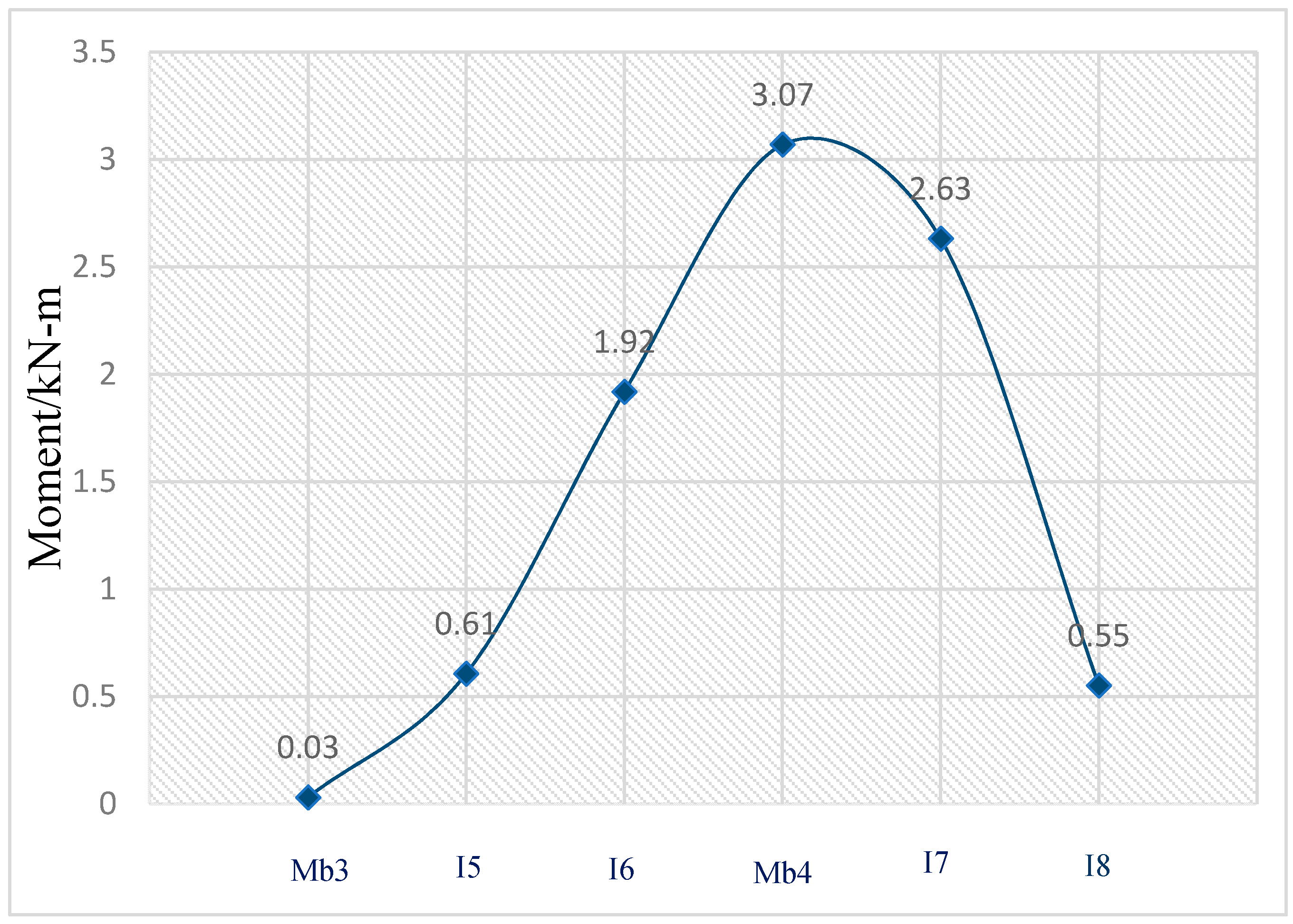
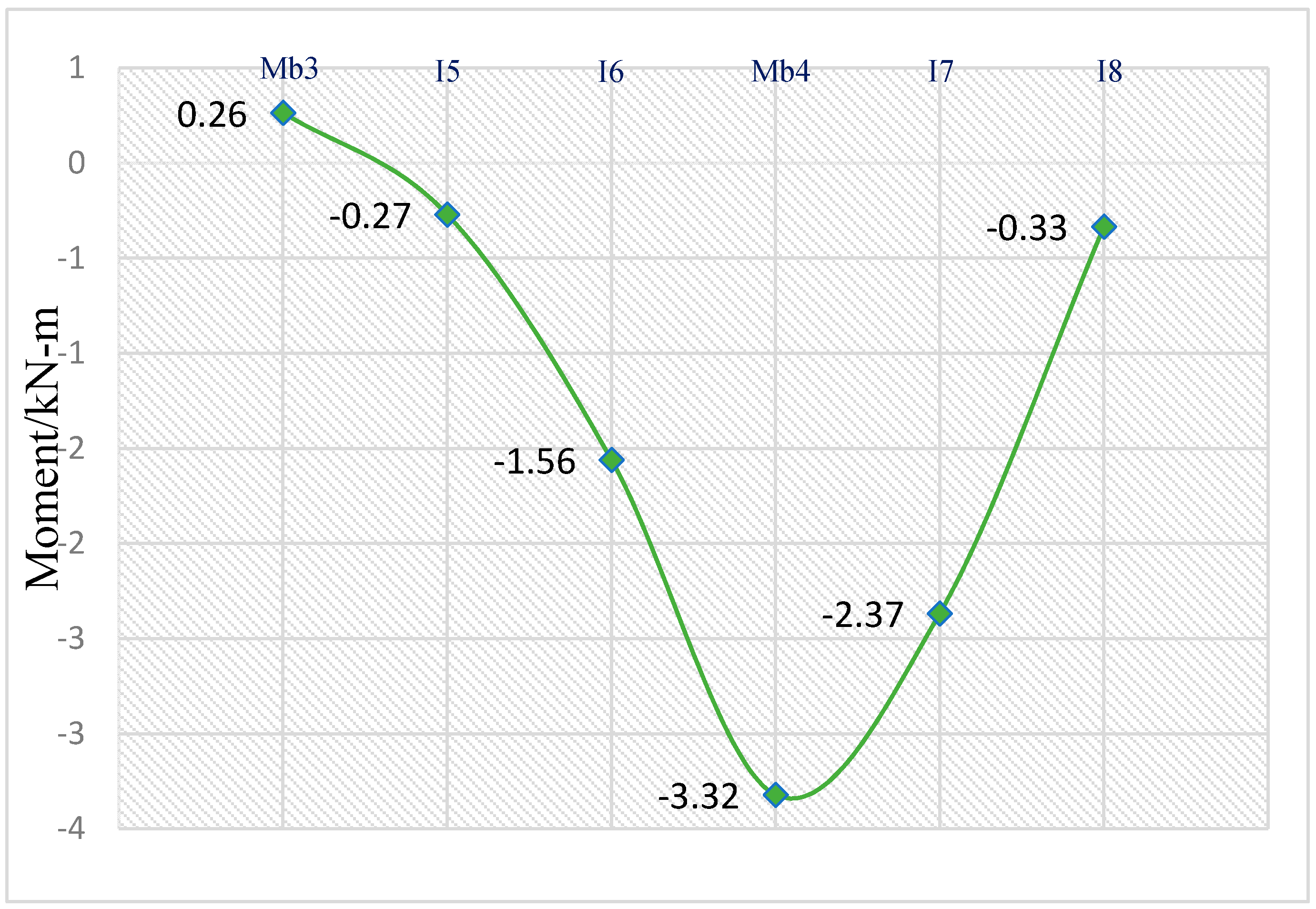
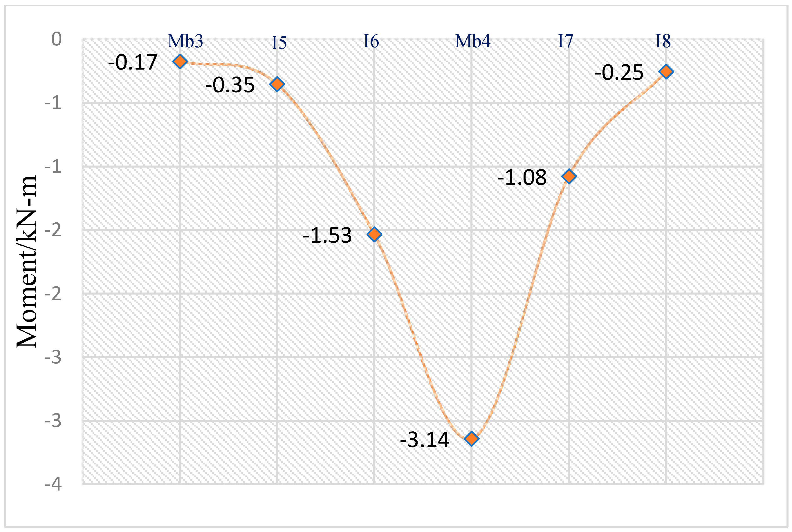
Moment Results Comparison
- a.
- Continuous beam analysis using SAP2000
- b.
- Influence lines in the continuous beam
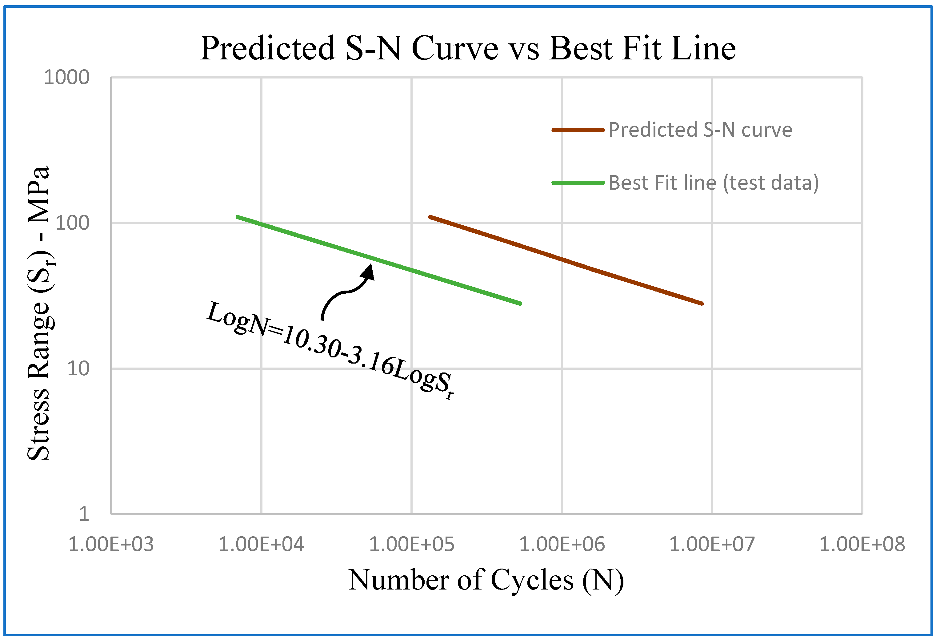
3. Fatigue Results from the Fracture Mechanics Model
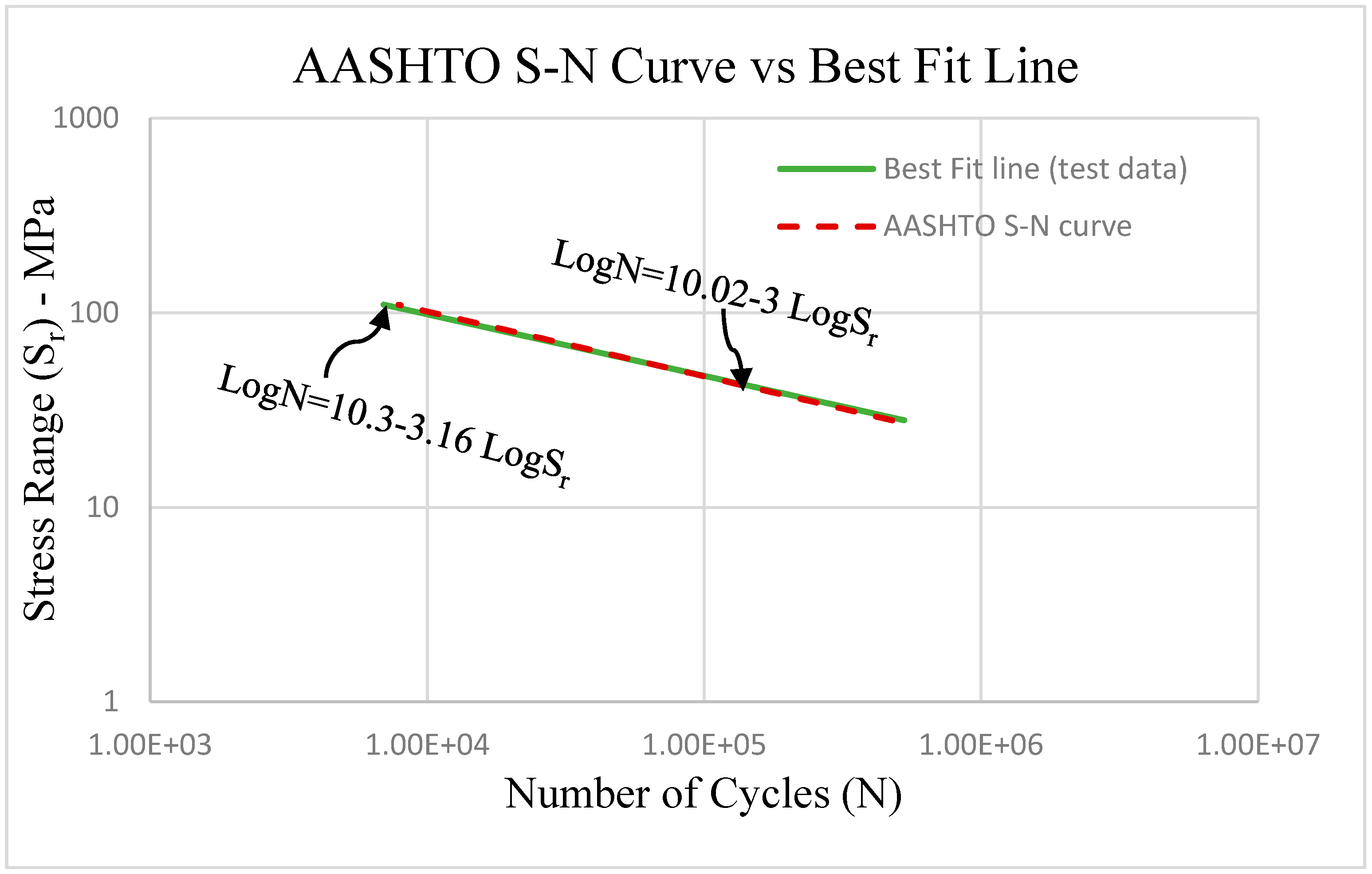
3.1. S-N Curves
Background
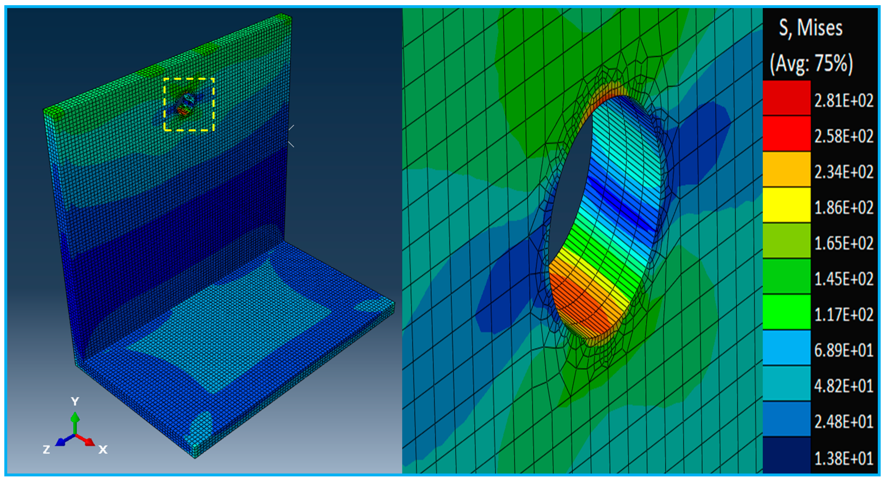
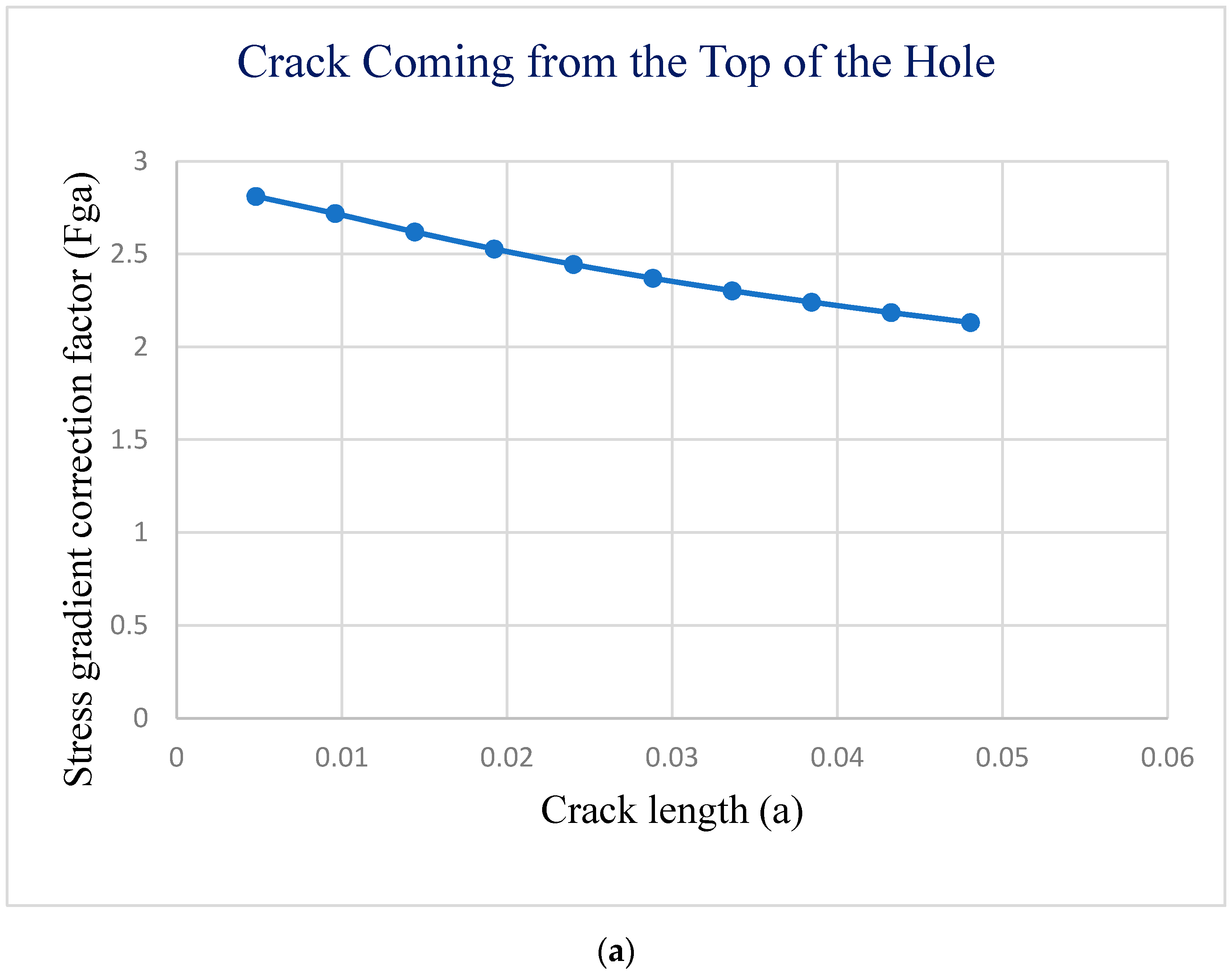
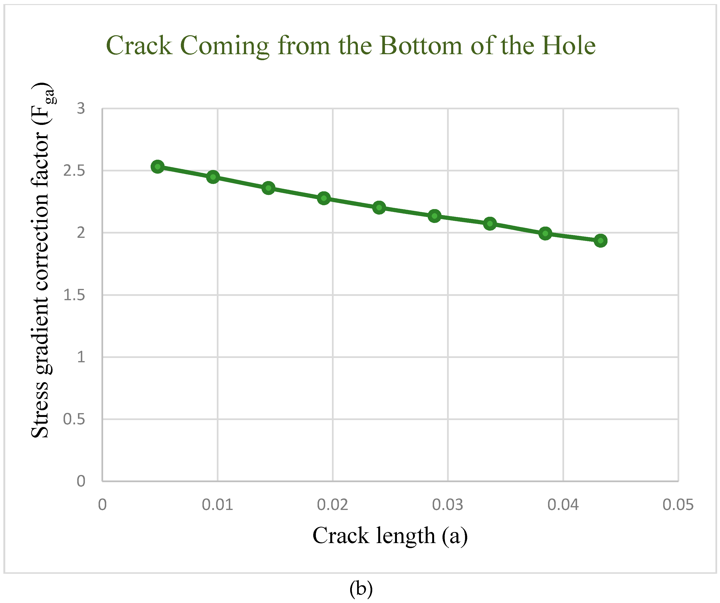
- The calculation of the stress gradient correction factor Fga using the following expression [3]:where ktj = stress concentration factor in element j of the finite element, lj = distance from the crack origin to the near and far, lj + 1 = sides of finite element j, and m = the number of elements to crack length a. After applying a moment of 2.8 kN-m (25 kips-in), we obtained the stress gradient around the rivet hole. Figure 14 shows the deformed shape and stress concentration due to a circular hole in the structure.
- 2.
- Accounting for the effect of a free surface on some finite length of crack, was calculated using five formulas [16]:where = crack length for each element, and W = crack width for the top and bottom.
- 3.
- The range of stress intensity factor ΔK was calculated as [3]:where Sr = stress range. Other notations are as previously noted.
- 4.
- Fourth, the calculation of fatigue crack growth per cycle by the use of Paris’s equation [11]:where a = length of the crack, N = number of cycles to failure, ΔK = the range of the stress intensity factor, and C and n are constants based on material properties, which, in our case for structural steel, C = 3.6 × 10⁻¹⁰, n = 3.
- 5.
- Finally, by rearranging Equation (7) and integrating between the initial and final crack sizes the number of cycles, N, can be predicted as [17]:where and represent initial crack size and the critical crack length respectively.
4. Conclusions
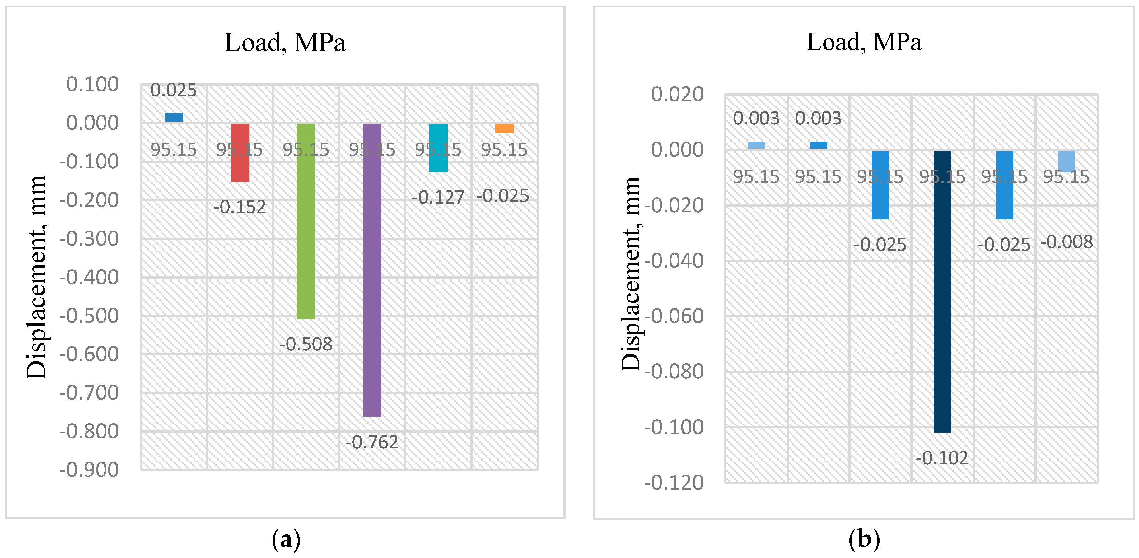
- The displacement for midspan ranges from near “zero” to −0.762 mm (“zero” to −0.030 in), with the largest value of −0.762 mm (−0.030 in) for the main bar directly under the tire patch load. However, the displacement is extremely small near the interior support for the main bar, as expected. The displacement average for the midspan was −0.254 mm (−0.010 in), and for the support it was near zero.
- The stress distribution was calculated for the bearing bar directly under the tire contact area as well as the adjacent bearing bars at a location 6.35 mm (0.25 in) from the top and bottom fiber of the bars. The highest value of tensile stress was 71 MPa (10.3 ksi) for the main bearing bar at the midspan; however, it was only 16 MPa (2.3 ksi) for the main bearing bar at the support, which is about 22% of the midspan value.
- Also, the compressive stresses at midspan and over the interior support were −31 and −7 MPa (−4.5 ksi and −1 ksi), respectively. In general, gratings had a total of six bearing bars and three actively participated in resisting the applied load.
- The manner of strain distribution was studied both in tension and in compression. The load is resisted mainly by the bearing bars located directly under the tire patch. In addition, the adjacent two intermediate bars provide some level of resistance, which was about 24% of the main bar directly under the load. A comparison was made between the midspan and interior support strain distributions, which demonstrated that it is concentrated at the midspan near the applied load. In general, the moment regions closest to the area of the applied load have larger strains compared to other regions.
- The largest positive bending moment for a single bearing bar was 3 kN-m (27 kips-in) which was recorded directly under the load at midspan.
- In addition, the maximum negative bending moment for a bearing bar was 3.3 kN-m (−29 kips-in) near the interior support B. The bending moment results obtained from the finite element analysis were compared to those obtained from different methods. The values were relatively close to each other.
- Fatigue analysis using fracture mechanics focusing on crack propagation around the rivet hole was used to predict the fatigue life of the heavy duty riveted grating. In fact, at a peak alternating stress of 69 MPa (10 ksi), we could expect that the structural components survive about 1,250,000 cycles.
- The line of best fit was close to the required AASHTO S-N curve.
Author Contributions
Funding
Institutional Review Board Statement
Informed Consent Statement
Data Availability Statement
Conflicts of Interest
References
- Kulak, G.L.; Fisher, J.W.; Struik, J.H. Guide to Design Criteria for Bolted and Riveted Joints, 2nd ed.; American Institute of Steel Construction, Inc.: Chicago, IL, USA, 2001. [Google Scholar]
- Åkesson, B. Fatigue Life of Riveted Steel Bridges; CRC Press: Boca Raton, FL, USA, 1995; pp. 1079–1084. [Google Scholar]
- Leonetti, D.; Maljaars, J.; Snijder, H.B. Fatigue life prediction of hot-riveted shear connections using system reliabil-ity. Eng. Struct. 2019, 186, 471–483. [Google Scholar] [CrossRef]
- Correia, J.A.; da Silva, A.L.; Xin, H.; Lesiuk, G.; Zhu, S.P.; de Jesus, A.M.; Fernandes, A.A. Fatigue perfor-mance prediction of S235 base steel plates in the riveted connections. Structures 2021, 30, 745–755. [Google Scholar] [CrossRef]
- Ohio Gratings Inc. Bridge Grating Solutions Components & Systems; Ohio Gratings Inc.: Canton, OH, USA, 2011. [Google Scholar]
- Ruzzante, A.; Pavan, R. Lightweight solution for existing steel movable bridge retrofit and repair. IOP Conf. Ser. Mater. Sci. Eng. 2018, 419, 012005. [Google Scholar] [CrossRef]
- Chandrupatla, T.R.; Belegundu, A.D.; Ramesh, T.; Ray, C. Introduction to Finite Elements in Engineering; Prentice Hall: Upper Saddle River, NJ, USA, 2002; Volume 2. [Google Scholar]
- Szymczyk, E.; Jachimowicz, J.; Sławinski, G.; Derewonko, A. Influence of technological imperfections on residual stress fields in riveted joints. Procedia Eng. 2009, 1, 59–62. [Google Scholar] [CrossRef] [Green Version]
- Rans, C.; Straznicky, P.V.; Alderliesten, R. Riveting process induced residual stresses around solid rivets in mechan ical joints. J. Aircr. 2007, 44, 323–329. [Google Scholar] [CrossRef]
- Wilson, E.L.; Habibullah, A. SAP2000, Structural Analysis Program; Computers and Structures, Inc.: Berkeley, CA, USA, 1995. [Google Scholar]
- Assakkaf, I.A. Review for Exam. Ph.D. Thesis, University of Maryland, College Park, MD, USA, 2003. [Google Scholar]
- Arthur, G.A. Fatigue Behavior and Design of Heavy Duty Riveted Steel Gratings in Bridge Decks. Ph.D. Thesis, University of Akron, Akron, OH, USA, 2014. [Google Scholar]
- Barsom, J.; Rolfe, S. Fracture and Fatigue Control in Structures: Applications of Fracture Mechanics; ASTM International: West Conshohocken, PA, USA, 1997. [Google Scholar]
- Daneshkhah, A.R.; Schlatter, C.R.; Rusnak, C.R.; Menzemer, C.C. Fatigue behavior of reinforced welded hand-holes in aluminum light poles. Eng. Struct. 2019, 188, 60–68. [Google Scholar] [CrossRef]
- ABAQUS, V. 6.14-5; Dassault Systemes: Pawtucket, RI, USA, 2014.
- Zettlemoyer, N. Stress Concentration and Fatigue of Welded Details. Ph.D. Dissertation, Lehigh University, Bethlehem, PA, USA, October 1976. [Google Scholar]
- Broek, D. Elementary Engineering Fracture Mechanics; Springer Science and Business Media LLC: Berlin, Germany, 6 December 2012. [Google Scholar]


| Bar# | At 6.35 mm (0.25 in) | Midspan Stress/MPa (ksi) | Bar# | At 6.35 mm (0.25 in) | Midspan Stress/MPa (ksi) |
|---|---|---|---|---|---|
| Mb3 | [01] T | −26 (−3.8) | Mb4 | [08] B | 71(10.3) |
| Mb3 | [02] B | 45.5 (6.6) | I7 | [09] T | −24.8 (−3.6) |
| I5 | [03] T | −21 (−3.1) | I7 | [10] B | −18 (−2.6) |
| I5 | [04] B | 7.5 (1.1) | I8 | [11] T | −23 (−3.4) |
| I6 | [05] T | −22.7 (−3.3) | I8 | [12] B | −5.5 (−0.8) |
| I6 | [06] B | 16.5 (2.4) | Mb5 | [13] T | −27.6 (−4) |
| Mb4 | [07] T | −31 (−4.5) | Mb5 | [14] B | 38 (5.5) |
| T = Top | B = Bottom | M = Main Bar | I = Intermediate Bar | ||
| Location@ | FEA Model kN-m (kips-in) | Continuous Beam Analysis kN-m (kips-in) | Hand Calculation kN-m (kips-in) |
|---|---|---|---|
| Support (B) | −7 (−63) | −5 (−44) | −5 (−45) |
| Midspan | 9 (78) | 9.3 (83) | 9.3 (82) |
| Support (C) | −6 (−54) | −5.5 (−49) | −5.6 (−50) |
Publisher’s Note: MDPI stays neutral with regard to jurisdictional claims in published maps and institutional affiliations. |
© 2021 by the authors. Licensee MDPI, Basel, Switzerland. This article is an open access article distributed under the terms and conditions of the Creative Commons Attribution (CC BY) license (https://creativecommons.org/licenses/by/4.0/).
Share and Cite
Abdulla, W.; Menzemer, C. Finite Element Analysis of Heavy Duty Riveted Steel Grating Bridge Deck. CivilEng 2021, 2, 485-501. https://doi.org/10.3390/civileng2020027
Abdulla W, Menzemer C. Finite Element Analysis of Heavy Duty Riveted Steel Grating Bridge Deck. CivilEng. 2021; 2(2):485-501. https://doi.org/10.3390/civileng2020027
Chicago/Turabian StyleAbdulla, Warda, and Craig Menzemer. 2021. "Finite Element Analysis of Heavy Duty Riveted Steel Grating Bridge Deck" CivilEng 2, no. 2: 485-501. https://doi.org/10.3390/civileng2020027
APA StyleAbdulla, W., & Menzemer, C. (2021). Finite Element Analysis of Heavy Duty Riveted Steel Grating Bridge Deck. CivilEng, 2(2), 485-501. https://doi.org/10.3390/civileng2020027