Article

Strengthening Strategies for Existing Rammed Earth Walls Subjected to Out-of-Plane Loading

1
Department of Culture, Ministry of Home and Cultural Affairs, Kawangjangsa, Thimphu 133, Bhutan
2
Graduate School of Design and Architecture, Nagoya City University, 2 Chome-1-10 Kitachikusa, Chikusa Ward, Nagoya, Aichi 464-0083, Japan
3
Faculty of Engineering and Design, Kagawa University; 2217-20 Hayashimachi, Takamatsu, Kagawa 761-0396, Japan
*
Author to whom correspondence should be addressed.
CivilEng 2020, 1(3), 229-242; https://doi.org/10.3390/civileng1030014
Submission received: 17 September 2020 / Revised: 24 October 2020 / Accepted: 27 October 2020 / Published: 30 October 2020
(This article belongs to the Special Issue Advances in Civil Engineering)

Abstract

:
The paper reports an experimental campaign to study the effectiveness of strengthening measures proposed for rammed earth (RE) wall in an out-of-plane direction. Two simple and feasible strengthening techniques were explored, namely, mesh-wrapped and timber-framed strengthening techniques. The test involved testing three full-scale U-shaped RE walls in an out-of-plane direction. The first specimen without any intervention served as the reference wall, while the two others were strengthened with two different strengthening methods. It was observed that both proposed strengthening techniques improved the load-carrying capacity of the wall and the maximum displacement and the energy absorption. The mesh-wrapped strengthening technique was found to be more effective than the timber-framed strengthening technique, which disrupted the visual aspects of the wall’s facade and needed proper anchoring to the foundation.

1. Introduction

Bhutan has a rich repository of rammed earth (RE) structures, which include an excellent variety of architectures ranging from simple houses to temples and fortresses. These structures are non-engineered and constructed by local craftsmen without any seismic-resilient features, and they are preserved and promoted as heritage structures. However, they suffered significant damages during the 2009 and 2011 earthquakes with magnitudes 6.3 and 6.9, respectively. The damage assessment report showed that a significant number of the buildings failed in out-of-plane loading [1].
The available literature on rammed earth wall is rich in studies on in-plane loading [2,3,4,5,6,7,8,9]; however, only a few have discussed out-of-plane behavior [10,11,12,13,14,15,16,17]. Further, studies have been carried out exploring strengthening measures to improve the seismic performance of existing rammed earth structures by using flax fiber reinforcement [18], polyester fabric strips [9], cement mortar–steel fiber reinforcement [19], mesh composite [20], and canvas and tarpaulin as externally bonded fibers [3]. All these measures deal with strengthening rammed earth wall in compression and in-plane loading.
Discussions on the effectiveness of out-of-plane strengthening techniques is limited [7,10,13]. All these proposed techniques are embedded within the rammed earth wall, and they are feasible only for a new construction, for example, post-tensioned vertical rebar [10,17], thinner section of reinforced concrete columns [7], and reinforced concrete dowels and wedges with a floor anchorage system [13]. Only a few studies have been conducted to assess the effectiveness of retrofitting measures, which include the use of externally bonded fiber [21], synthetic meshes [22], and steel plates [23]. All these tests are conducted under a shaking table test on a reduced-scale wall [21] and an L-shaped wall [22,23], which do not necessarily reproduce the actual response of buildings.
Therefore, in this study, a full-scale U-shaped wall was chosen whose orthogonal wall represents the facade wall and side walls represent the transverse walls. The study would assess the effectiveness of a strengthening measure suitable for existing buildings in an out-of-plane direction under static loading, which would be the first of its kind. Possible strengthening solutions were explored for rammed earth wall, which have never been discussed before. Furthermore, the study would contribute to the limited literature that aims to understand the out-of-plane behavior of rammed earth wall. The feasibility and effectiveness of the proposed strengthening technique were assessed by conducting pull-down tests on three sets of full-scale specimens under out-of-plane loading. The first wall, with no reinforcement, served as a reference wall, and the second and third walls were strengthened with a mesh and timber-framed system. The proposed strengthening techniques were kept simple, and the materials used are readily available in the local market to ensure widespread utilization of these techniques. Although strengthening works were carried out for undamaged wall, this method was largely aimed at improving the strength of existing rammed earth walls in an out-of-plane direction. This work is an extension of the authors’ previous works [5,12,13,14,20,24], which largely focused on numerical modelling, reinforced RE with reinforced dowels and wedges, floor anchorage system, and mesh-wrapped strengthening on reduced-scale walls. The present study aimed to evaluate the feasibility and effectiveness of the two proposed strengthening techniques, which could be adopted in retrofitting the rammed earth buildings in Bhutan.

2. Specimen and Materials
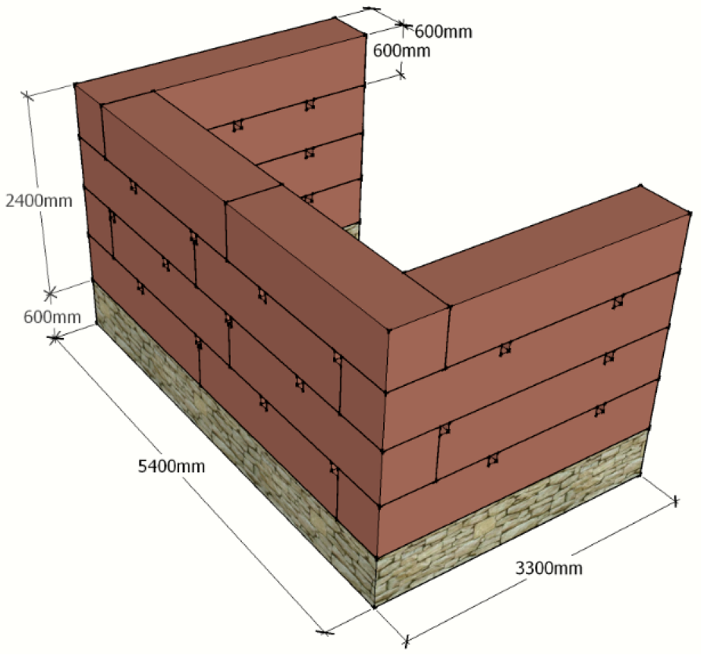
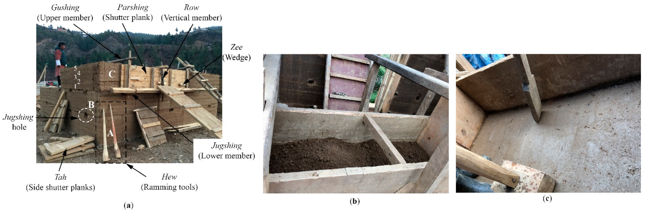
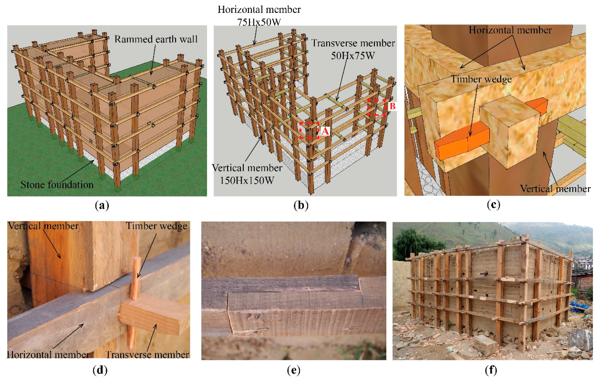
2.1. Specimen

The experimental program included a pull-down test of U-shaped wall to understand the out-of-plane behavior of rammed earth wall while assessing the feasibility and effectiveness of the proposed strengthening techniques. The test specimen prototype represented a real-scale wall facade and transverse walls. Three U-shaped full-scale rammed earth walls were constructed, namely, unreinforced rammed earth (U-RE), mesh-wrapped strengthened rammed earth (Mesh-RE), and timber-framed strengthened rammed earth (Timber-RE). The unreinforced rammed earth (U-RE) represented a typical house built without any seismic components, and it served as the reference wall, while the rammed earth wall strengthened with a mesh and timber frame were aimed at retrofitting existing buildings. The details of the adopted specimen are presented in Figure 1, and Figure 2 illustrates the grain size distribution of the soil used [5]. All specimens were constructed on top of a rubble masonry foundation of 600 mm height and 600 mm thickness by local Bhutanese craftsmen following the traditional construction procedures practiced in the region to realize the actual behavior of such structures. The construction process for RE wall involved the installation of wooden formwork, as shown in Figure 3a, which consisted of (i) shutter planks on both sides, (ii) horizontal joining members at the top and bottom, (iii) and vertical members to connect the shutter planks and horizontal members. The local term for each formwork component is shown in the figure in italic word. Wedges were inserted between the vertical members and shutter planks to keep the formwork stable, thus preventing the wall from bulging. This single formwork section gave a rammed earth block of around 2500 mm length, 600–700 mm height, and 600 mm thickness. The next step included pouring of moistened earth inside the formwork (Figure 3b), followed by compaction of 240 mm soil to around 120 mm manually with wooden ramming tools. The water content in the mixture was checked through a traditional field test. A handful of moist earth was squeezed and tossed up in the air about a meter away from the ground, and the mixture was considered suitable if, upon falling on the ground, it broke into two or three major pieces [12,24]. The final finished RE block looked smooth and shiny (Figure 3c). A single block consisted of five layers labeled as 1, 2, 3, 4, and 5 in Figure 3a. The formwork was removed immediately and reinstalled to construct the next block. The blocks in the corners were placed alternatively to avoid a continuous head joint between the two rammed earth blocks marked A, B, and C in Figure 3a.
The specimen Mesh-RE was strengthened with a locally available mesh, wrapped around the entire surface of the specimen in both faces of the wall (Mesh-RE). The mesh had 1.45 mm diameter with a square pitch of 28 mm. The mechanical properties of the mesh were derived based on the ASTM E8 2016 standard [25]. The mesh steel had yield and fracture stress of 396 MPa and 476 MPa, respectively. The strengthening work began after 2 weeks of drying period. The mesh was placed in both the inside and outside faces of the wall (Figure 4a), connected by a horizontal timber member inserted inside the jugshing holes and nails, as shown in Figure 4b. A lapping length of 200 mm was provided in both horizontal and vertical directions to connect the meshes at disjointed locations and corners. Before applying the mortar, the wall surface was moistened adequately, followed by spraying of dry cement to ensure proper bonding between the wall and the plaster. A final covering was provided by applying 30 mm thick stabilized earth-based plaster (1 cement: 4 earth) over the mesh, as shown in Figure 4d. The idea of using earth-based plaster was to maintain the aesthetic view of the rammed earth wall while protecting the mesh against the weather. Figure 4e presents a view of Mesh-RE after completion of plastering work, where the plaster is seen to be aesthetically compatible to its substrate rammed earth wall. Changes in current cement and earth proportion, with increment in the percentage of cement, can result in an appearance different from the actual rammed earth. It should be noted that durability issues and detachment of stabilized mortar provided as covering to the mesh in the present study require further detailed study. The present work proposes clamping of the meshes at two faces of the wall through the jugshing holes, which would enable the wall to retain its effectiveness despite losing the mortar over time. The strengthening work was completed in August 2018. The specimen Mesh-RE was tested in October 2018 after a curing period of 1 month for the mesh plaster.
The specimen Timber-RE was strengthened with a timber-framed system that consisted of vertical, horizontal, and transverse members, as illustrated in Figure 5a,b. The timber used here had a flexural strength, σ b T , of 62.08 MPa [13,26]. The strengthening work included the preparation of timber members and joineries. The chronology of installing the timber members involved fixing the vertical members on both faces, followed by fixing horizontal members over them at an interval of 600 mm, connecting all the vertical members together (Figure 5b). Finally, these members were connected through timber wedges, forming a confined frame. The jugshing holes made it possible to insert the transverse members across the wall’s cross section to connect the outer and inner frames. The intersection of these members was joined by a timber wedge, as detailed in Figure 5c,d. Due to the limitation of the timber length, the horizontal members were joined together by nails, and at least 200 mm lapping length was maintained (Figure 5e). Poor workmanship leads to weaker joints at the intersection points and lapping region; therefore, extra attention was taken at such regions. Figure 5f shows a view of specimen Timber-RE after completion of the strengthening works. The specimen Timber-RE was tested at the same time with the specimen Mesh-RE in October 2018.

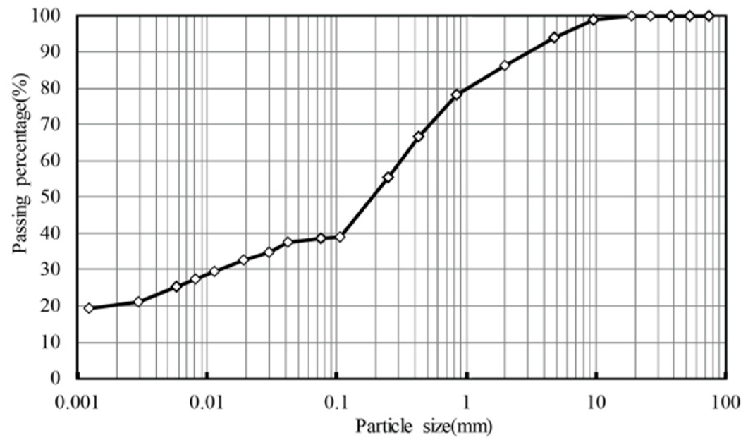
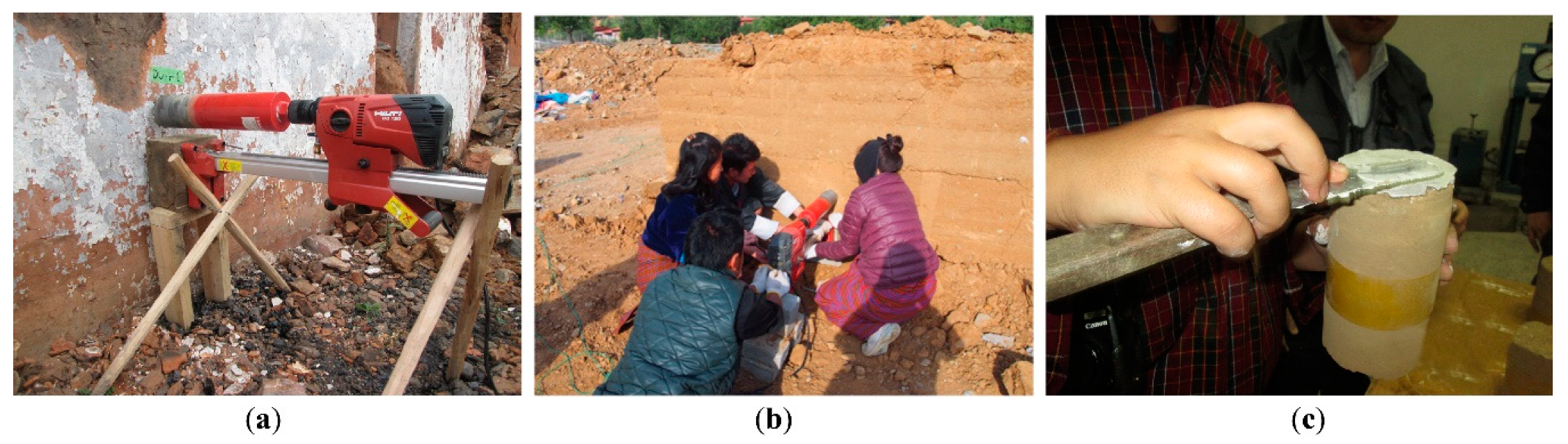
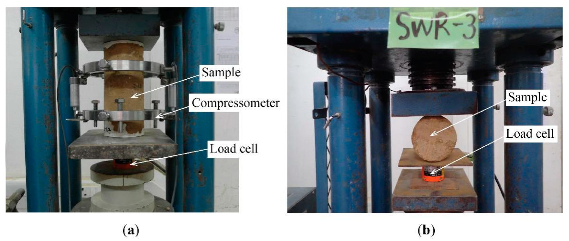
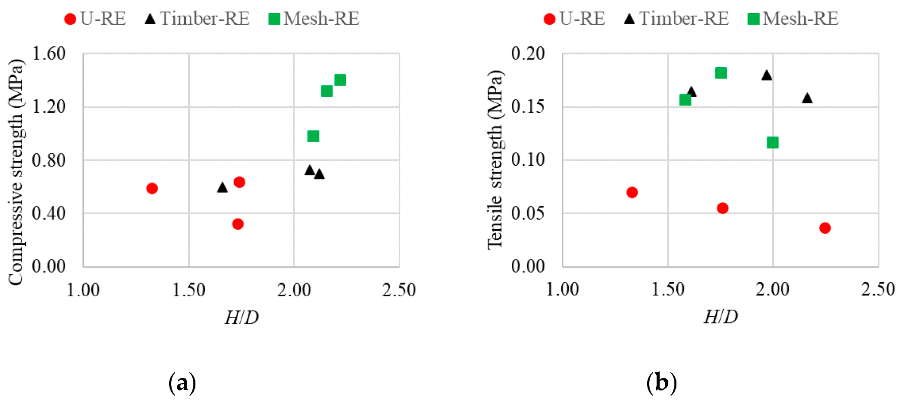
2.2. Material Characterization
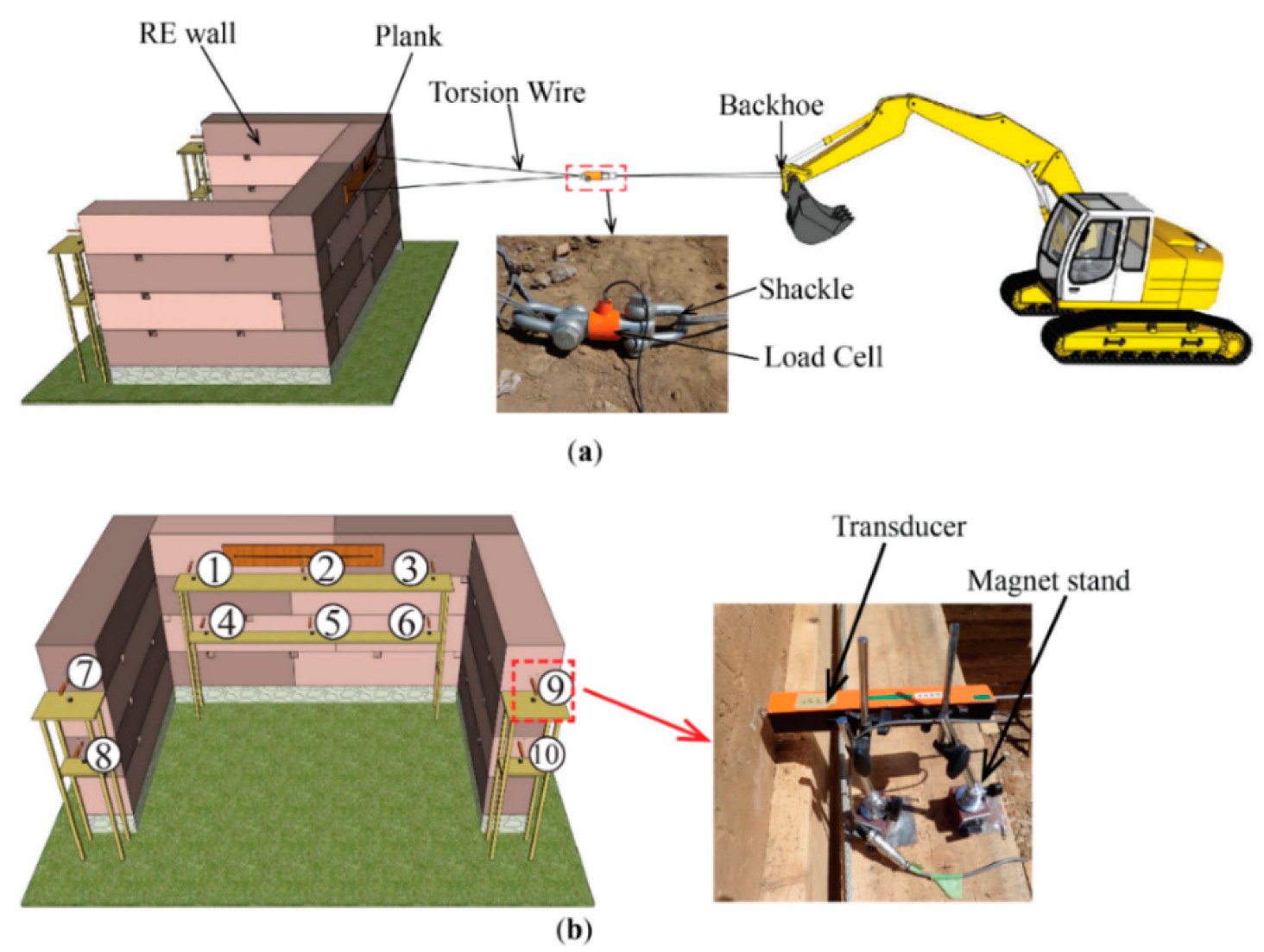
Right after the completion of the pull-down test, samples were extracted using a core drill machine with a diameter of 100 mm (DD120, Hilti Corporation), as shown in Figure 6a,b. It can be observed from the figure that the direction of the extraction was parallel to the rammed earth layer. For Mesh-RE, the extraction was followed after peeling off the mesh layer. Samples were first trimmed and capped with white cement plaster to ensure a flat surface at both the top and bottom surfaces (Figure 6c). Three samples were tested each under compression and tensile strength testing. Due to the difficulty of core drilling of rammed earth, the length of the extracted cylindrical samples varied from one another. The samples had diameters ranging from 92 to 94 mm and lengths ranging from 146 to 200 mm. For the stabilized earth-based plaster (1 cement: 4 earth), three cylindrical samples were prepared in the standardized molds with 100 mm diameter and 200 mm height. The samples had an average diameter and length of 99.98 mm and 197.58 mm, respectively.
The compressive strength and splitting tensile tests on cylindrical samples were conducted according to ASTM C39 [27] and ASTM C496 [28], respectively. The tests were conducted in the Bhutan Standards Bureau (BSB). The test setups for compressive strength testing are presented in Figure 7a, and tensile strength testing is shown in Figure 7b. Here, the load applied was measured through the compressive load cell (KCM-200KNA, TML (Tokyo Measuring Instruments Laboratory Co., Ltd., Shinagawa Ward, Tokyo, Japan), which was then recorded in a multichannel dynamic strainmeter, DS-50A (TML), with LAN interface setting. The vertical displacement was recorded by a high-sensitivity strain gauge installed within the compressometer (CM-10, TML). The test results from the material characterization are summarized in Table 1. The maximum average dry density observed was 2045 kg/m3 for Mesh-RE and the minimum observed was 1926 kg/m3 for Timber-RE. The difference in strength characteristics of the rammed earth samples was observed, although they were constructed from the same soil composition. Such variability was influenced by the place where the samples were extracted [13]. It should be noted that core drilling was done within a single layer, avoiding the interface between the layers. Further, the core drill samples were extracted in a horizontal direction perpendicular to the direction of ramming. The anisotropy of rammed earth [29] affecting material characterization tests is not within the scope of this paper. The samples extracted from the location favoring the wall drying had higher strength than the samples extracted from the least-favored drying place. Furthermore, it was influenced by the gradient of density from the bottom section to the top section of the wall due to the construction process involving manual ramming [30]. The elastic modulus reported in Table 1 was calculated from the elastic–linear range of the compressive stress–strain curve, between around 0% and 40% of the maximum compressive strength. Figure 8 shows the effect of the ratio of height (H) and diameter (D) of the extracted samples on compressive and tensile strengths. Clearly, there was minimal effect of the H/D ratio on the strength characteristics of the tested core samples.

2.3. Test Setup

Figure 9a shows the experimental test setup for the out-of-plane pull-down test. Due to the nonavailability of the testing facility, the pull-down load was applied with the help of a crane. The pull-down load was applied on the facade wall, 2100 mm from the foundation top, to execute the out-of-plane mechanism. The facade wall was pulled in a horizontal direction with the backhoe of the crane. To distribute a uniform load to the wall, a 40 mm thick plank was fixed on two faces of the wall. The planks, along with the facade wall, were wrapped with a torsion wire (16 mm diameter) to apply the pulling force. The provision to insert the torsion wire was kept during the wall construction. The load applied on the wall was measured by the tension load cell (TLP-200 kNB), as shown in Figure 9a. As seen in the figure, the load cell had two shackles at both ends, where one end was connected to the backhoe and the other end was connected to the wall with the help of a torsion wire. The load data were recorded in a TML multichannel dynamic strainmeter (DS-50A) using LAN interface setting. The horizontal displacements of the wall were measured by displacement transducers (SDP-100C with 20 m cable). Six of them (sensors 1–6) were placed at the back of the facade wall, and four of them (sensors 7–10) were placed at the back of the transverse walls as shown in Figure 9b. The transducers at the top and midlevel were set at 1900 mm and 1100 mm, respectively, from the foundation top.

3. Results and Discussion

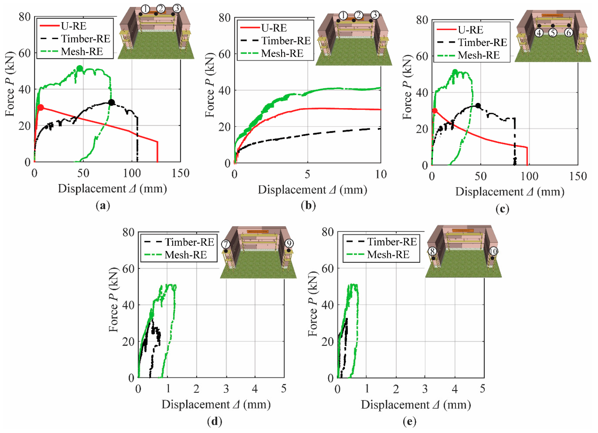
3.1. Load–Displacement Relationship

Figure 10 shows the relationship between the pull-down force and horizontal displacement for U-RE, Mesh-RE, and Timber-RE. The plot for the pull-down load for each specimen is made against the displacements at the top level of the facade wall (mean of sensors 1, 2, and 3) in Figure 10a, midlevel of the facade wall (mean of sensors 4, 5, and 6) in Figure 10c, top level of the transverse walls (mean of sensors 7 and 9) in Figure 10d, and midlevel of the transverse walls (mean of sensors 8 and 10) in Figure 10e. Figure 10b shows a zoomed-in curve of Figure 10a with displacement up to 10 mm, showing the elastic and initial crack phase of the wall. The initial stiffness, reported in Table 2, was calculated as the ratio of the pull-down load to the corresponding out-of-plane displacement up to the linear range of the load–displacement curve. Clearly, a slight improvement in stiffness was observed in the Mesh-RE and Timber-RE specimens as an effect of the mesh-wrapped and timber-framed strengthening techniques. From Figure 10d,e, it is clear that the back section of the transverse walls showed deformation for both Mesh-RE and Timber-RE. The larger deformation of the back walls of Mesh-RE attributes to the effectiveness of the mesh-wrapped technique in uniting the facade wall and the transverse walls. It should be noted that for U-RE, the deformation of the transverse wall was negligible and thus was not reported in Figure 10d,e. The peak load recorded for each specimen is marked by the red, green, and black circles for U-RE, Mesh-RE, and Timber RE, respectively, and it is also reported in Table 2. It was observed that the peak pull-down load recorded for Mesh-RE and Timber-RE was 1.72 times and 1.09 times their unreinforced counterpart, respectively. Further, the corresponding displacements at peak load at the top level of the facade wall for Mesh-RE and Timber-RE were 46.17 mm and 78.95 mm, respectively, which are 7.76 times and 13.27 times the U-RE.
From the load-displacement curve of the U-RE, it was observed that there was a sharp increment in the load until the maximum pull-down load. Once it reached its peak load, the facade wall suddenly collapsed, showing the brittle nature of rammed earth. A similar case was reported for unreinforced wall tested under in-plane loading [3]. Only one zone was observed for U-RE before the peak. However, the pull-down load-displacement curve of Mesh-RE and Timber-RE was characterized by three zones before the maximum pull-down load and one zone after the peak load, as presented in Figure 11. In the first zone (zone A), the load–displacement curve was almost linear, representing the uncracked zone. In zone B, the crack initiated in the mesh plaster for Mesh-RE, and there was disconnection in the joineries and intersections of the timber members in the case of Timber-RE. The third zone (zone C) was characterized by a gradual increment in load until it reached the maximum pull-down load. At this stage, the existing cracks in the mesh plaster widened due to mesh elongation for Mesh-RE. In the case of Timber-RE, a sharp splitting sound of timber was heard due to dislocation. Gradually, the bed joint crack evolved in the rammed earth wall for both Mesh-RE and Timber-RE. The fourth zone (Zone D) was the post-peak behavior of Mesh-RE and Timber-RE, showing a larger deformation capacity with almost a quasi-constant load until the failure. This larger deformation capacity after the peak shows that the strengthening measures adopted are effective in delaying the out-of-plane collapse of the facade and distributing the load over the larger section of the wall. Such improvement in deformation capacity with the use of strengthening measures was also reported in previous studies [3,22].
The energy absorption (Ψ) is given by the area under the force–displacement curve until a 10% drop in the maximum load [18]. The energy absorption (Ψ) for each specimen is listed in Table 2. Both Mesh-RE and Timber-RE showed better energy absorption than U-RE. The energy absorption values for Mesh-RE and Timber-RE were 4.33 and 3.15 times that for U-RE, respectively.

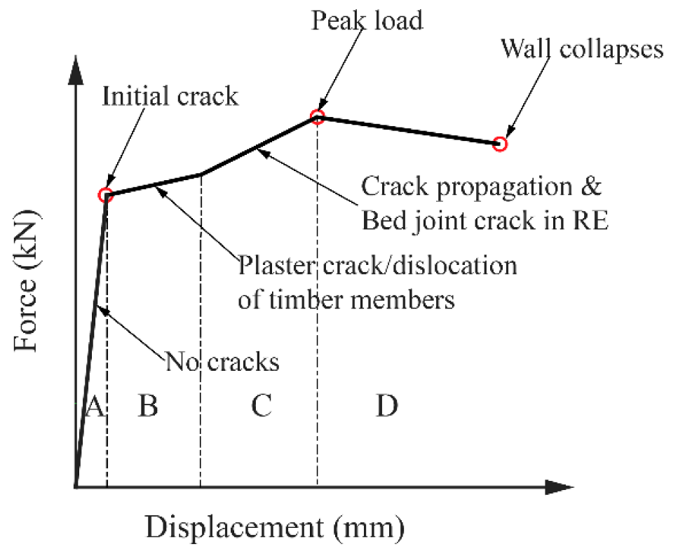
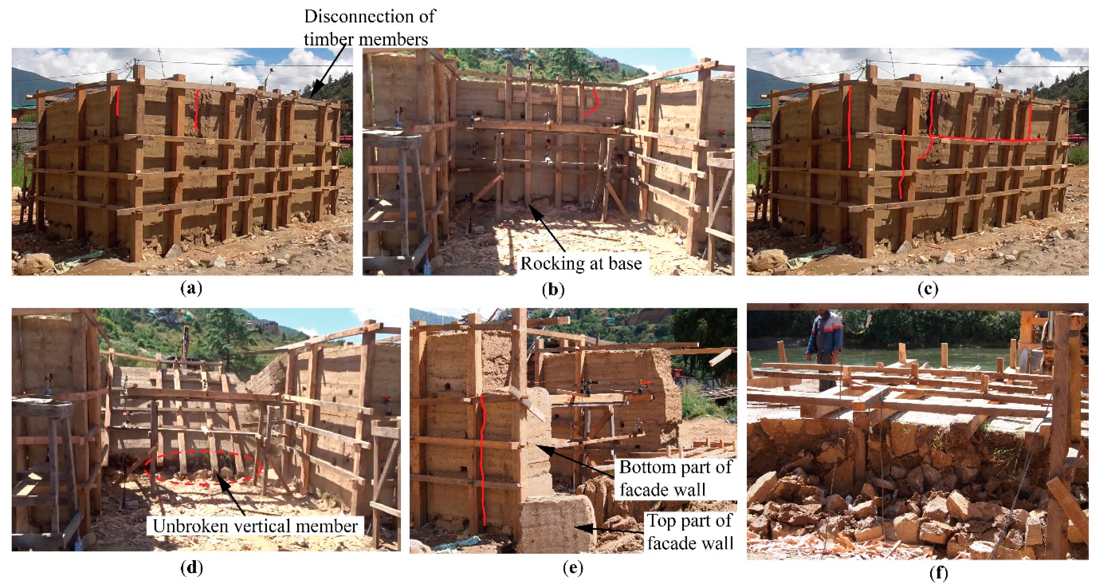
3.2. Failure Mechanism

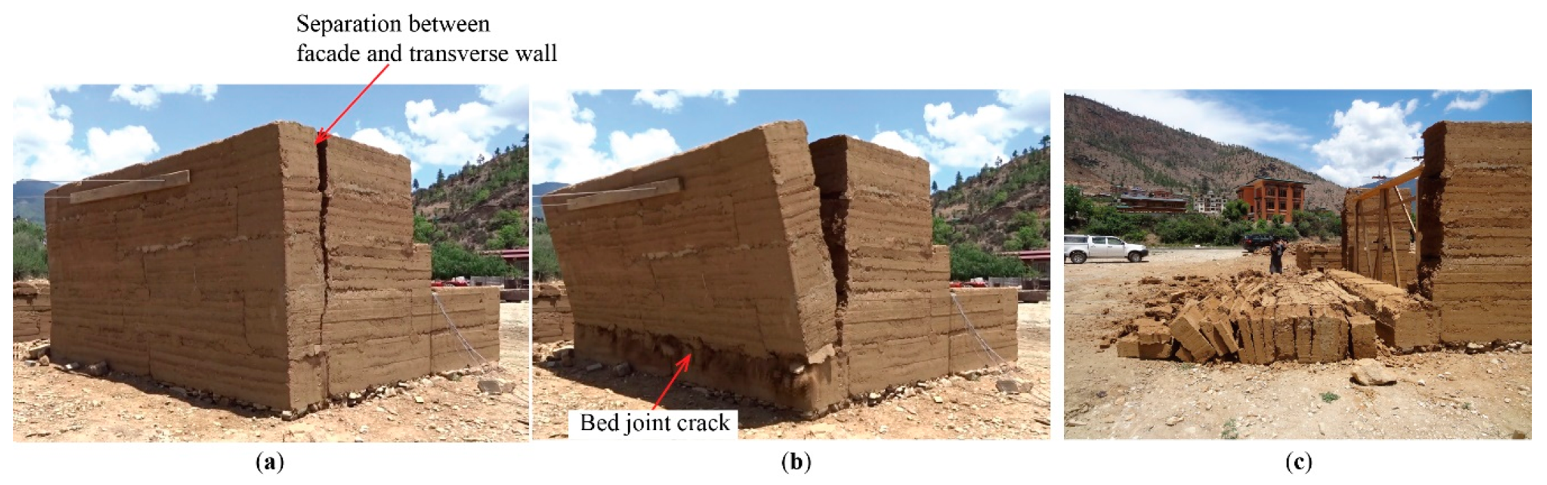
3.2.1. Unreinforced Rammed Earth Wall (U-RE)

The failure mode observed in U-RE is reported in Figure 12. The failure mode was initiated with the separation of the facade wall from the two transverse walls, at the top of the wall. The crack widened and extended downward with the rigid-body rocking of the front facade, as shown in Figure 12a. The front facade wall then overturned, forming a bed joint crack with the first-layer block, as shown in Figure 12b. Figure 12c shows the final collapse of the wall. The separation of the facade wall from the side walls shows the lack of connection in the corner. The overturning behavior characterized by the separation of the top blocks from the first block shows a lack of vertical connection between the blocks.

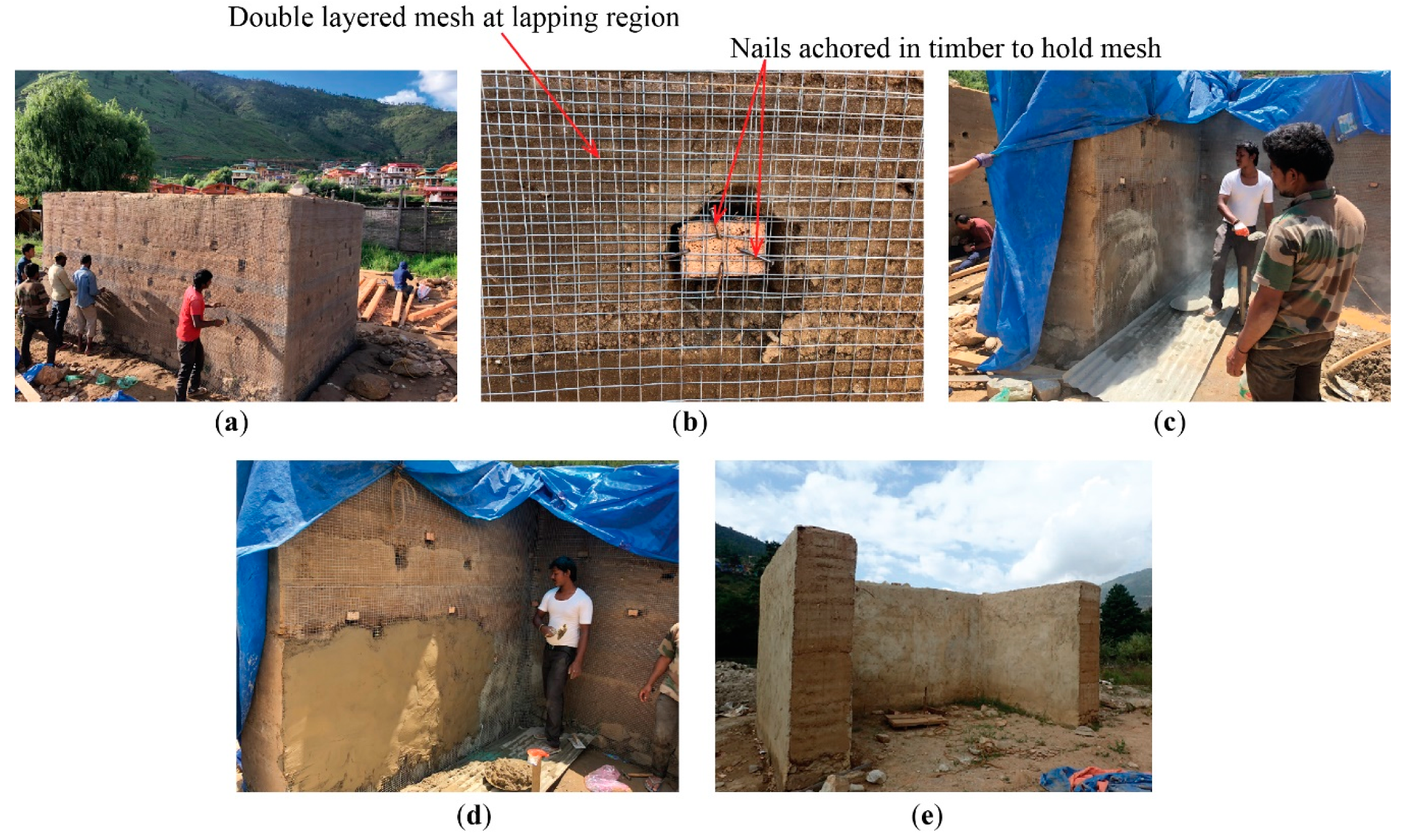
3.2.2. Mesh-Wrapped Strengthened Rammed Earth Wall (Mesh-RE)

The failure of the Mesh-RE wall was preceded by the appearance of the plaster cracks in the back side of the front facade near the loading point, as illustrated in Figure 13a. In the next stage, the plaster crack in the left corner of the wall initiated, and simultaneously, a plaster crack also emerged on the right side of the front wall away from the corner (Figure 13b). Till this stage, there were no traces of cracks from the front view of the facade wall. On further application of the load, the previously existing plaster cracks in the corners widened and propagated downward with clear visibility of the mesh inside. The bed joint crack also exhibited, characterized by the bulging of the top block of the facade wall, as shown in Figure 13c. The wall continued to displace until the top block of the wall collapsed with the tearing of the mesh, as illustrated in Figure 13d. Figure 13e,f shows the final view of Mesh-RE from the front and back, respectively. The final failure mode was local with a sliding of the top RE block; however, before that, there was effective load transfer over the wall’s section through mesh-wrapped strengthening characterized by the deformation of the transverse walls. Throughout the loading process, the cracks were seen within the mesh–plaster, and no delamination of plaster was seen. The delamination of the mesh with tearing at the lapping region and plaster spalling at the front facade was observed only at the final failure. Further, mesh strengthening retained a relatively large portion of the top block with controlled failure, preventing the crack at the bed joint and overturning of the entire facade as observed in the case of U-RE.

3.2.3. Timber-Framed Strengthened Rammed Earth Wall (Timber-RE)

Figure 14 presents the failure mode observed for Timber-RE. During the pull-down, a strong splitting sound of timber was heard, and the topmost transverse member near the right-hand corner of the facade wall split its connection with the other members. Then, the cracks initiated in the rammed earth wall near the corner and loading point. The crack initiation can be seen in Figure 14a from the front and Figure 14b from the back. At this point, rocking of the facade wall was also observed, as illustrated in Figure 14b. The cracks then propagated downward as the pull-down continued. A vertical crack near the other end of the loading point emerged, followed by a horizontal bed joint crack in between the third and fourth blocks, as seen in Figure 14c. The wall collapsed with overturning at the base. An apparent disconnection of the facade wall from the transverse walls was observed (Figure 14d). The vertical members at the back face of the facade wall overturned without any breakage but lost their connection from the foundation (Figure 14d). It shows the inadequacy of timbers’ anchorage inside the foundation. Figure 14e,f presents an overview of the final failure mode from the front and back, respectively. From Figure 14e, it is observed that the bottom portion of the facade wall was retained, although there was clear separation between the facade and the transverse walls.
The importance of having enough embedded length and proper anchorage inside the foundation was clearly understood from the observations above. However, this may not be practical in a real building since the width of the stone foundation is larger than the rammed earth wall; the vertical member cannot be embedded within the earth, and it can only be rested on top of the stone foundation. Furthermore, the use of a timber frame around the wall disrupts the visual aspects of the rammed earth wall. Nevertheless, a timber frame can be useful as a first intervention in case of emergency to secure and prevent the collapse of unsafe wall sections.
It should be noted that no instrumentation was placed to measure the actual sliding of the walls during the pull-down tests. However, it was clear through the video recordings and visual observations that sliding failure mode was not observed.

4. Conclusions

In this paper, the effectiveness of two types of structural intervention in rammed earth wall loaded in an out-of-plane direction was studied through a pull-down test. One of the strengthening techniques included providing a mesh around the wall, and the other approach included providing a confined timber-framed system. The unreinforced specimen showed minimal resistance against out-of-plane loading with typical rocking characteristics and collapse of the whole front facade. The use of the mesh-wrapped strengthening technique and confined timber-framed system helped to unite the front facade and transverse walls; particularly, the mesh-wrapped technique showed improved performance with a controlled failure mechanism. The comparative results showed significant improvements in the load-carrying capacity with both methods of structural intervention up to 1.72 times with the use of mesh-wrapped strengthening and 1.09 times with the use of a confined timber-framed system. Both interventions were able to delay the collapse of the RE wall. Further, both intervention techniques improved the energy absorption, where Mesh-RE was 4.33 times and Timber-RE was 3.15 times the U-RE.
Among the two techniques considered, timber framing was found to clearly disrupt the visual aspects of the wall’s facade, and further, it needed special considerations for anchoring the vertical posts to the foundation. On the other hand, the mesh-wrapped strengthening technique was found to be a comparatively simpler and practical approach for retrofitting an existing RE wall. However, it is important to connect the meshes at both faces of the wall to avoid the detachment of the mesh while adopting the proposed technique. The authors’ future research will involve the application of the proposed strengthening technique in a real-sized building of usual Bhutanese building typology with openings.

Author Contributions

Conceptualization, P.W., K.C.S., T.A., M.M. and P.; methodology, P.W., K.C.S., T.A., M.M. and P.; validation, P.W., K.C.S., T.A., M.M. and P.; formal analysis, P.W., K.C.S., T.A. and M.M.; investigation, P.W., K.C.S., T.A., M.M. and P.; resources, P.W., K.C.S., T.A., M.M. and P.; data curation, P.W., K.C.S., T.A., M.M. and P.; writing—original draft preparation, P.W.; writing—review and editing, P.W., K.C.S., T.A. and M.M.; supervision, K.C.S., T.A. and M.M.; project administration, P.W., K.C.S., T.A., M.M. and P.; funding acquisition, T.A. All authors have read and agreed to the published version of the manuscript.

Funding

This research was funded by JST/JICA, SATREPS (Science and Technology Research Partnership for Sustainable Development) project, grant number JPMJSA1611.

Acknowledgments

The authors would like to acknowledge the technical assistance of Engineer Kunzang Tenzin, Engineer Ugyen Dorji, and Technician Lhendup from the Department of Culture, Ministry of Home and Cultural Affairs, Royal Government of Bhutan, in undertaking the experimental works. The authors would also like to thank the Bhutan Standards Bureau for granting permission to use the test facility for the material tests.

Conflicts of Interest

The authors declare no conflict of interest.

References

  1. DCHS. Damage Assessment of Rammed Earth Buildings-After the September 18: 2011 Earthquake; Division for Conservation of Heritage Sites, Department of Culture, Ministry of Home and Cultural Affairs, Royal government of Bhutan: Thimphu, Bhutan, 2011.
  2. Miccoli, L.; Drougkas, A.; Müller, U. In-plane behaviour of rammed earth under cyclic loading: Experimental testing and finite element modelling. Eng. Struct. 2016, 125, 144–152. [Google Scholar] [CrossRef]
  3. Liu, K.; Wang, M.; Wang, Y. Seismic retrofitting of rural rammed earth buildings using externally bonded fibers. Constr. Build. Mater. 2015, 100, 91–101. [Google Scholar] [CrossRef]
  4. El-Nabouch, R.; Bui, Q.B.; Plé, O.; Perrotin, P. Assessing the in-plane seismic performance of rammed earth walls by using horizontal loading tests. Eng. Struct. 2017, 145, 153–161. [Google Scholar] [CrossRef]
  5. Shrestha, K.C.; Aoki, T.; Miyamoto, M.; Wangmo, P.; Pema. In-plane shear resistance between the rammed earth blocks with simple interventions: Experimentation and finite element study. Buildings 2020, 10, 57. [Google Scholar] [CrossRef] [Green Version]
  6. Arslan, M.E.; Emiroğlu, M.; Yalama, A. Structural behavior of rammed earth walls under lateral cyclic loading: A comparative experimental study. Constr. Build. Mater. 2017, 133, 433–442. [Google Scholar] [CrossRef]
  7. Zhou, T.; Liu, B. Experimental study on the shaking table tests of a modern inner-reinforced rammed earth structure. Constr. Build. Mater. 2019, 203, 567–578. [Google Scholar] [CrossRef]
  8. Miccoli, L.; Oliveira, D.V.; Silva, R.A.; Müller, U.; Schueremans, L. Static behaviour of rammed earth: Experimental testing and finite element modelling. Mater. Struct. Constr. 2015, 48, 3443–3456. [Google Scholar] [CrossRef]
  9. Miccoli, L.; Müller, U.; Pospíšil, S. Rammed earth walls strengthened with polyester fabric strips: Experimental analysis under in-plane cyclic loading. Constr. Build. Mater. 2017, 149, 29–36. [Google Scholar] [CrossRef]
  10. Hamilton, H.R.; McBride, J.; Grill, J. Cyclic testing of rammed-earth walls containing post-tensioned reinforcement. Earthq. Spectra 2006, 22, 937–959. [Google Scholar] [CrossRef]
  11. Miyamoto, M.; Pema; Aoki, T.; Tominaga, Y. Pull-down test of the rammed earth walls at Paga Lhakhang in the Kingdom of Bhutan. Int. J. Sustain. Constr. 2014, 2, 51–59. [Google Scholar] [CrossRef]
  12. Wangmo, P.; Shrestha, K.C.; Miyamoto, M.; Aoki, T. Assessment of out-of-plane behavior of rammed earth walls by pull-down tests. Int. J. Archit. Herit. 2019, 13, 273–287. [Google Scholar] [CrossRef]
  13. Shrestha, K.C.; Aoki, T.; Miyamoto, M.; Wangmo, P.; Pema; Zhang, J.; Takahashi, N. Strengthening of rammed earth structures with simple interventions. J. Build. Eng. 2020, 29, 101179. [Google Scholar] [CrossRef]
  14. Shrestha, K.C.; Aoki, T.; Konishi, T.; Miyamoto, M.; Zhang, J.; Takahashi, N.; Wangmo, P.; Aramaki, T.; Yuasa, N. Full–Scale Pull–Down Tests on a Two–Storied Rammed Earth Building with Possible Strengthening Interventions. In Proceedings of the Structural Analysis of Historical Constructions, Cusco, Peru, 11–13 September 2018; RILEM Bookseries. Elsevier: Amsterdam, The Netherlands, 2019; pp. 1557–1565. [Google Scholar]
  15. Bui, T.L.; Bui, T.T.; Bui, Q.B.; Nguyen, X.H.; Limam, A. Out-of-plane behavior of rammed earth walls under seismic loading: Finite element simulation. Structures 2020, 24, 191–208. [Google Scholar] [CrossRef]
  16. Dong, X.; Griffith, M.; Soebarto, V. Feasibility of rammed earth constructions for seismic loads in Australia. Aust. J. Struct. Eng. 2015, 16, 262–272. [Google Scholar] [CrossRef] [Green Version]
  17. Bui, Q.B.; Bui, T.T.; El-Nabouch, R.; Thai, D.K. Vertical Rods as a Seismic Reinforcement Technique for Rammed Earth Walls: An Assessment. Adv. Civ. Eng. 2019, 2019, 1285937. [Google Scholar] [CrossRef]
  18. Cheah, J.S.; Morgan, T.K.K.B.; Ingham, J.M. Cyclic testing of a full-size stabilized, flax-fibre reinforced earth (uku) wall system with openings. In Proceedings of the 14th World Conference on Earthquake Engineering 2008, Beijing, China, 12–17 October 2008; pp. 1–8. [Google Scholar]
  19. Pang, M.; Yang, S.; Zhang, Y. Experimental study of cement mortar-steel fiber reinforced rammed earth wall. Sustainability 2012, 4, 2630–2638. [Google Scholar] [CrossRef] [Green Version]
  20. Wangmo, P.; Shrestha, K.C.; Aoki, T. Exploratory study of rammed earth walls under static element test. Constr. Build. Mater. 2020, 266, 121035. [Google Scholar] [CrossRef]
  21. Wang, Y.; Wang, M.; Liu, K.; Pan, W.; Yang, X. Shaking table tests on seismic retrofitting of rammed-earth structures. Bull. Earthq. Eng. 2017, 15, 1037–1055. [Google Scholar] [CrossRef]
  22. Reyes, J.C.; Smith-Pardo, J.P.; Yamin, L.E.; Galvis, F.A.; Angel, C.C.; Sandoval, J.D.; Gonzalez, C.D. Seismic experimental assessment of steel and synthetic meshes for retrofitting heritage earthen structures. Eng. Struct. 2019, 198, 109477. [Google Scholar] [CrossRef]
  23. Reyes, J.C.; Rincon, R.; Yamin, L.E.; Correal, J.F.; Martinez, J.G.; Sandoval, J.D.; Gonzalez, C.D.; Angel, C.C. Seismic retrofitting of existing earthen structures using steel plates. Constr. Build. Mater. 2020, 230, 117039. [Google Scholar] [CrossRef]
  24. Roberto, P.; De Filippi, F.; Bosetti, M.; Aoki, T.; Wangmo, P. Influence of Traditional Building Practices in Seismic Vulnerability of Bhutanese Vernacular Rammed Earth Architecture. Int. J. Archit. Herit. 2020, 1–20. [Google Scholar] [CrossRef]
  25. ASTM. Standard E8/E8M Tension Testing of Metallic Materials; ASTM International: West Conshohocken, PA, USA, 2016. [Google Scholar]
  26. J.I.S. Z2101 Methods of Test for Woods. Jpn. Wood Res. Soc. 2009. Available online: https://infostore.saiglobal.com/en-us/Standards/JIS-Z-2101-2009-627076_SAIG_JSA_JSA_1456446/ (accessed on 10 September 2020).
  27. ASTM. C39 Standard Test Method for Compressive Strength of Cylindrical Concrete Specimens: C39/C39M-18; ASTM International: West Conshohocken, PA, USA, 2018. [Google Scholar]
  28. ASTM. C496 Standard Test Method for Splitting Tensile Strength of Cylindrical Concrete Specimens; ASTM International: West Conshohocken, PA, USA, 2011. [Google Scholar]
  29. Bui, Q.B.; Morel, J.C. Assessing the anisotropy of rammed earth. Constr. Build. Mater. 2009, 23, 3005–3011. [Google Scholar] [CrossRef]
  30. Bui, Q.B.; Morel, J.C.; Hans, S.; Meunier, N. Compression behaviour of non-industrial materials in civil engineering by three scale experiments: The case of rammed earth. Mater. Struct. Constr. 2009, 42, 1101–1116. [Google Scholar] [CrossRef]
Figure 1. Specimen details.
Civileng 01 00014 g001
Figure 2. The grain size distribution of the soil used.
Civileng 01 00014 g002
Figure 3. Construction details of U-RE specimen: (a) Rammed earth at third block showing formwork details, (b) Loose earth inside formwork before compaction, (c) Smooth and shiny finish after compaction.
Civileng 01 00014 g003
Figure 4. Strengthening process for mesh-wrapped rammed earth wall (Mesh-RE): (a) Fixing mesh and anchoring, (b) Details of anchorage of mesh, (c) Spraying dry cement on wetted wall, (d) Stabilized mud mortar plastering, (e) View of Mesh-RE.
Civileng 01 00014 g004
Figure 5. Strengthening process for rammed earth wall with timber-framed system (Timber-RE): (a) Proposed timber frame strengthening, (b) Timber frame details, (c) Detail A, (d) Detail B, (e) Lapping in horizontal member, (f) View of completed Timber-RE on site.
Civileng 01 00014 g005
Figure 6. Sample collection: (a) Hilti core drill machine, (b) core sampling, (c) capping with white cement.
Civileng 01 00014 g006
Figure 7. Material characterization test: (a) compression test, (b) splitting tensile test.
Civileng 01 00014 g007
Figure 8. Size effect on the material strength: (a) compression strength, (b) tensile strength.
Civileng 01 00014 g008
Figure 9. Test setup: (a) overview of out-of-plane pull-down test, (b) locations of displacement transducers.
Civileng 01 00014 g009
Figure 10. Load displacement relationship: (a) at the top level of the facade wall, (b) zoomed at the top level of the facade wall, (c) at the midlevel of the facade wall, (d) at the top level of the transverse walls, (e) at the midlevel of the transverse walls.
Civileng 01 00014 g010
Figure 11. The typical load–displacement curve of the strengthened rammed earth wall.
Civileng 01 00014 g011
Figure 12. Failure mode of U-RE: (a) crack initiation, (b) bed joint crack, (c) final failure mode.
Civileng 01 00014 g012
Figure 13. Failure mode of Mesh-RE: (a) crack initiation mesh plaster, (b) vertical cracks in mesh plaster, (c) bed joint crack in RE, (d) tearing of mesh, (e) and (f) final failure mode from the front and back view, respectively.
Civileng 01 00014 g013
Figure 14. Failure mode of Timber-RE: (a) and (b) crack initiation in RE from the front and back view, respectively; (c) propagation of cracks and bed joint crack; (d) view of the wall showing an unbroken vertical member; (e) and (f) final failure mode of the wall from the side and back view, respectively.
Civileng 01 00014 g014
Table 1. Results of material characterization of rammed earth samples and stabilized earth-based mortar.
SpecimenBulk Density (kg/m3)Compressive Strength (MPa)Tensile Strength (MPa)Elastic Modulus (MPa)
MeanCoVMeanCoVMeanCoVMeanCoV
U-RE20330.140.520.270.050.252200.92
Mesh-RE20450.020.860.150.150.183510.12
Timber-RE19260.110.680.080.170.063580.01
Stabilized earth-based mortar18090.024.610.38--11050.37
CoV—coefficient of variation.
Table 2. Summary of experimental results.
SpecimenPeak Load (kN)K
(kN/mm)
Δpeak
(mm)
Ψ
(kN-mm)
U-RE29.9914.515.95810.6
Mesh-RE51.4726.3546.173517.5
Timber-RE32.6444.5778.952551.2
K—initial stiffness, Δpeak—displacement at peak load, Ψ—energy absorption.
Publisher’s Note: MDPI stays neutral with regard to jurisdictional claims in published maps and institutional affiliations.

