1. Introduction
Permanent-magnet synchronous motors (PMSMs) exhibit significant potential for use in belt conveyor drives in the mining industry due to their unique performance characteristics, including a high torque density, excellent energy efficiency, and a wide speed control range. However, sophisticated and customized control systems are essential to fully exploit the capabilities of PMSMs [
1,
2]. Conventional control systems increasingly demonstrate limitations under the challenging operating conditions of conveyor belts in the mining industry [
3]. For example, basic speed control methods often fail to maintain constant speed and accurate torque reproduction under significant load variations, resulting in reduced conveyor efficiency and accelerated equipment wear [
4,
5,
6]. These operational challenges are further compounded by frequent load shocks and mechanical resonances unique to mining conveyors, demanding control systems with exceptional disturbance rejection capabilities to prevent material spillage, minimize unplanned downtime, and reduce the maintenance costs associated with belt degradation.
The advent of model predictive control (MPC) [
7,
8,
9] has opened up new possibilities for utilizing permanent-magnet synchronous motors (PMSMs) in mining belt conveyors. MPC predicts future states using its mathematical model and adjusts control actions in real time according to predefined optimization targets, thereby achieving enhanced control performance under challenging operating conditions. The integration of vector control and active disturbance suppression techniques is expected to address the limitations of traditional control methods and fulfill the requirements for high-performance control of drive motors in mining belt conveyors [
10,
11,
12]. However, both MPC and ADRC show areas open to optimization. For example, when addressing high-frequency decisions and large-scale problems, MPC demands substantial computing power, and tackling this could optimize the real-time performance of MPC [
13]. ADRC is often criticized for relying on accurate prior knowledge of object dynamics to explicitly define a structure capable of effectively reducing object disturbances and uncertainties [
14].
Ref. [
15] proposed an improved model predictive current control strategy, which reduced current harmonics and torque pulsation by optimizing the cost function design. However, this study neglected the impact of parameter uncertainty and external disturbances on the system. Ref. [
16] further improved the current tracking performance of MPC by introducing delay compensation and the adaptive adjustment of weight factors. However, it relies on an accurate motor model, and its performance may degrade due to model mismatch in load time-varying scenarios, such as in belt conveyors. In contrast, the ADRC-MPC hybrid control strategy proposed in this paper estimates and compensates for the unknown disturbances in the conveyor system in real time through the disturbance observer of ADRC, making up for the dependence of traditional MPC on model accuracy. Ref. [
17] designed an adaptive linear prediction model and achieved full-speed domain optimization control by switching the prediction model parameters. However, the problem of nonlinear disturbance suppression was not solved. This paper compares five control methods, analyzes their characteristics, and experimentally validates the advantages of the ADRC + MPC method.
For multi-phase motor control, ref. [
18] applied MPC to the direct torque control of a five-phase PMSM and reduced torque pulsation through multi-vector synthesis. However, the control complexity was relatively high. Ref. [
19] used parallel computing to accelerate the solution process of nonlinear MPC, offering an engineering implementation reference for the proposed algorithm in transport scenarios with high real-time requirements. In the field of sensorless control, ref. [
20] combined the unscented Kalman filter (UKF) with MPC to achieve position estimation in a PMSM, but it relied on high-precision sensor data. This paper, based on the characteristics of belt conveyor speed control, uses ADRC’s ESO to directly estimate load disturbances and speed signals, reducing hardware costs.
This paper systematically pursues three core research objectives—implementing a PMSM vector control methodology using MPC through the comprehensive modeling and simulation of mining conveyor systems, establishing an accurate motor model via the rigorous investigation of vector control and MPC theory, and conducting extensive verification through simulation studies—which collectively provide a clear framework for the subsequent technical exposition.
This paper details the implementation of a permanent-magnet synchronous motor vector control method using model predictive control within the modeling and simulation of a belt conveyor control system in the mining industry [
21,
22,
23]. The establishment of an accurate motor model, a thorough study of vector control theory and model predictive control, and extensive verification through simulation [
24,
25,
26] were designed to establish a more efficient, reliable, and adaptive control scheme for belt conveyors in the mining industry. This contributes to the development of automation technology and the intelligent control of transport equipment in the mining industry and the improvement of overall mining efficiency [
27,
28].
2. Mathematical Modeling of Permanent-Magnet Synchronous Motor Control
In the synchronous rotor coordinate system, for time characteristics such as voltage, permanent-magnet circuits are converted into time-invariant parameters to simplify analysis [
29,
30]. In addition, the following assumptions have been established for this control system to facilitate its operation [
31,
32]:
- –
The stator windings consist of three symmetrically distributed and identical phases, with the axis of each winding being spatially different and the angular distance between them being 120°.
- –
Assuming the absence of magnetic circuit saturation, hysteresis, and eddy currents, the rotor does not experience damping.
- –
The current in the windings is sinusoidal only when there are no gaps.
- –
The stator electromotive force is sinusoidal when the motor is running without load.
In the three-phase stationary ABC coordinate system, the voltage equation for a permanent-magnet synchronous motor is expressed as follows:
where
represents the three-phase voltage,
is the resistance of the stator winding, and
is the magnetic circuit of the three-phase winding [
33,
34].
The three-phase magnetic circuit of the stator of a permanent-magnet synchronous motor is as follows:
where
is the inductance of the stator winding, and
is the magnetic circuit created by the permanent magnet on the stator winding.
According to the theory of electromechanical energy conversion, the electromagnetic torque
is equivalent to the change in the stored magnetic field energy (stored magnetic field energy) with respect to the mechanical angular position
θ, which leads to the following equation:
where
p is the number of pole pairs of a permanent-magnet synchronous motor.
The mechanical equations of motion for the system are as follows:
where
is the load torque,
B is the viscous friction coefficient,
ω is the mechanical angular velocity of the motor, and
J is the moment of inertia.
From Equations (1)–(4), we can conclude that the mathematical model of the permanent-magnet synchronous motor is very complex and the variables are strongly related to each other. Hence, it is necessary to perform decoupling and coordinate transformation in the motor modeling process.
Firstly, the Clarke transformation is carried out, which is the transformation of the current flow based on the three-axis two-dimensional stationary stator coordinate system to the two-axis stationary stator coordinate system, called 3 s/2 s.
The Clark transformation matrix is shown below:
Then, the matrix of the inverse Clark transform has the form:
Hence, the voltage equation of a permanent-magnet synchronous motor in the
α-
β coordinate system is as follows:
where the counter electromotive forces
and
are satisfied as follows:
where
is the electromechanical angular velocity (
),
is the rotor position angle,
is the permanent-magnet (PM) magnetic circuit,
are the voltages of the permanent-magnet synchronous motor on the
and
axes, respectively, and
are the currents of the permanent-magnet synchronous motor on the α and
axes, respectively [
35].
Secondly, the stationary coordinate system is converted to the synchronous rotating coordinate system using the Park transform.
The matrix of the Park transformations is shown below:
Then, the inverse transformation of Park is of the form:
Thus, the stator voltage equation for a permanent-magnet synchronous motor in the
coordinate system can be obtained as follows:
where
are the stator voltage components on the
axes,
are the stator current components on the
axes,
and
are the inductance components on the
axes, and for motors with surface magnets
=
.
The electromagnetic torque equation for a permanent-magnet synchronous motor in the
coordinate system is as follows:
In this section, the equations for motor voltage, flux, electromagnetic torque, and mechanical motion in a three-phase stationary coordinate system are given, emphasizing that the model is complex and the relationship between the variables needs to be transformed. The specific research method will be explained below.
3. Velocity Contour Control Using Active Disturbance Suppression Techniques
In PMSM vector control systems, ADRC is widely used for velocity loop control. In particular, ADRC can observe the combined effect of internal and external perturbations of the system in real time and accurately compensate for them, so as to eliminate the influence of nonlinear factors and enable precise decoupling control of the velocity loop. Therefore, in this paper, ADRC is used to control the velocity loop.
LADRC is mainly composed of linear state error feedback (LSEF), LESO, and total perturbation compensation. Its schematic diagram is shown in
Figure 1.
The mathematical model has the following form:
where
and
are the inputs and outputs of the system, respectively;
is the unknown perturbation of the system;
is the system parameters; and
is the input control gain. The simplification of Equation (13) gives the following:
where
is the sum of perturbations of the system;
is the gain of the known part.
Let us write down the state variables:
Then, Equation (15) can be transformed into the following:
According to Equation (16), the expression for the second-order LESO is as follows:
where
,
are LESO state variables.
,
are the observer parameters. By choosing suitable values for
and
, the state variables in LESO can quickly and accurately track the state variables of the system; i.e.,
tracks the output y of the system and
tracks the sum of perturbations
of the system. LESO is used to observe the sum of system perturbations and compensate the system for the perturbations and the controller output:
LSEF uses proportional control with a control law:
where
is the proportional control coefficient. The ADRC parameters are configured as follows:
where
is the bandwidth of the controller;
is the bandwidth of the observer. Then, the configuration of ADRC parameters can be simplified as the selection of appropriate
and
.
If the mathematical model of the PMSM is taken as the object of study, the traditional ADRC is used in the velocity loop to obtain its model:
where
is the angular velocity reference value;
is the proportional control coefficient.
4. Current Control Loop MPC
In a belt conveyor control system, the use of MPC as a current loop controller significantly improves the system stability and response speed. With the ability to predict and optimize the control actions in real time, MPC ensures the stable operation of the conveyor under different operating conditions, improving the efficiency and reliability of the conveying process. Therefore, this paper proposes the use of MPC to control the current loop of a PMSM (permanent-magnet synchronous motor).
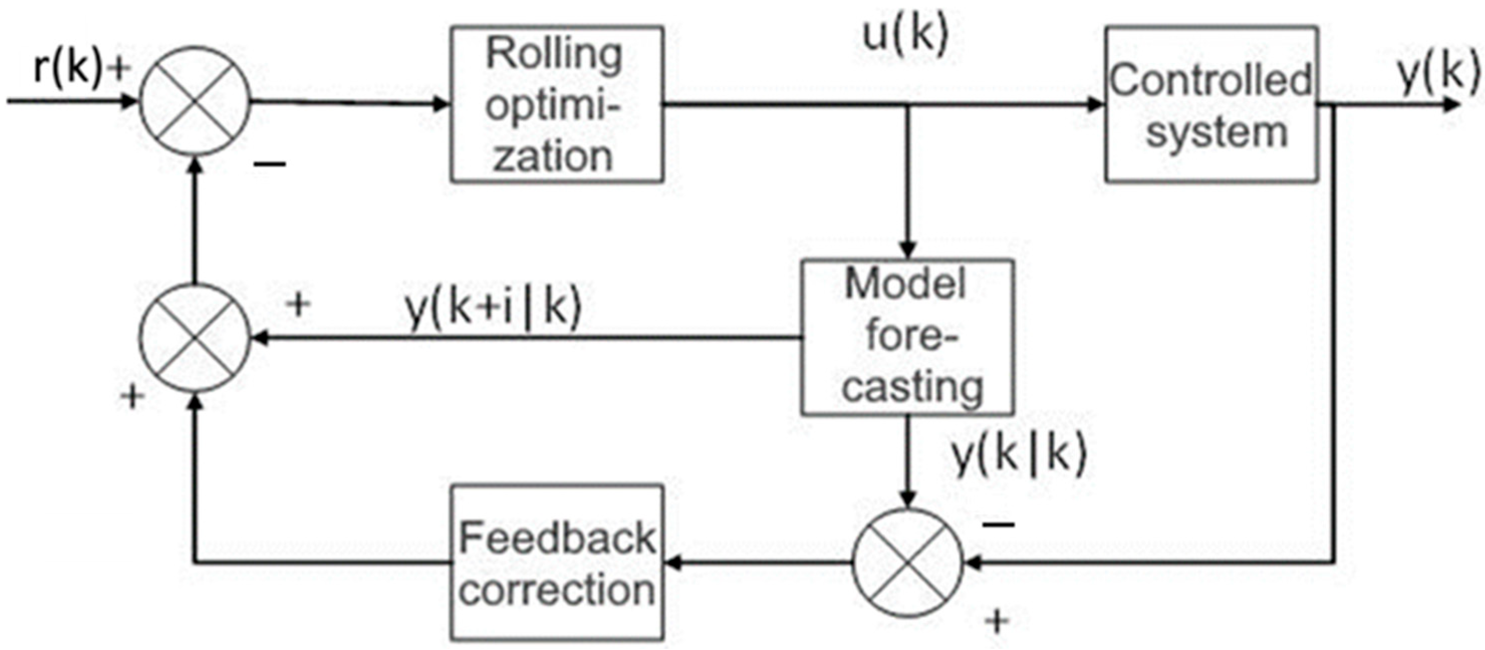
The core concept is to use a certain dynamic model to predict the system behavior and determine the optimal solution value, i.e., the current control value, by optimizing the prediction results. The schematic diagram is demonstrated in
Figure 2.
In this figure, is the reference value of the system, is the output value of the system, and is the control signal. is the predicted output value for the next i steps obtained after using the model prediction.
Predictive modeling involves using the mathematical model of the controlled system to predict the output of the system at the next N moments of time.
Model predictive control (MPC) is a control method in which calculated control actions minimize a cost function for a constrained dynamic system over a finite, decreasing horizon. At each time step, the MPC controller obtains or estimates the current state. Rolling optimization consists of solving an optimization problem in a finite time domain at each sampling time to minimize the error between the predicted output and the desired output, while satisfying different system constraints.
Feedback correction consists of comparing the actual measured output of the system with the predicted output to obtain the prediction error. The model is adjusted based on the prediction error to improve the prediction accuracy.
MPC can predict future d-axis and q-axis current changes based on the dynamic model of the controlled system and calculate the optimal control actions using an optimization algorithm to achieve fast response and accurate current control.
The stator current model for the PMSM in the d-q coordinate system can be obtained according to Equation (11).
The differential current equation is described using Euler’s method to get the differential current equation in the following form:
The discrete state-space current model can be expressed as follows:
The model can also be obtained in the following form:
Let us set the moment of the stabilization point equal to
; then,
Model (25) can be transformed by subtracting the following equations:
where
If the system constraints are not considered, the MPC is equivalent to linear–quadratic optimal control with a finite prediction step in the time domain. In this case, a limiting link is added to the output part of the model predictive controller. Let us define the variables as follows: the state variable , the output variable , and the input variable and control variable .
At
k moment in time, the predicted value at the
k +
N-th moment of time is equal to the following:
Thus, the forecasting model in matrix form is as follows:
where
I is a second-order unit matrix, and then the cost function equation can be constructed based on this current loop prediction model in the following form:
where
represents the reference current values along the
d- and
q-axis, and
Q and
R are the coefficients of the weight matrix. The MPC law for the current loop can be obtained by deriving the cost function:
The solution is as follows:
The final control variable is the input voltage:
Prediction is used in MPC. The model predicts the changes in d-axis current and q-axis current, predicts N steps, and selects only the result of one step to produce the output data.
5. Vector Control of the PMSM
Vector control is used to achieve accurate motor control by decomposing the PMSM stator current into two orthogonal components to control the magnetic field and torque of the motor, respectively. This method emulates the approximate control characteristics of AC motors to those of DC motors with fast dynamic response and high torque control accuracy.
Vector control includes zero DC control, weak magnetization control, and maximum output power control.
Weak magnetization control is mainly performed by adjusting the d-axis current to maintain a stable motor torque during high-speed operation. Maximum power output control is mainly used to optimize the current distribution on the d and q axes so that the motor can produce maximum power under different operating conditions, which is suitable for high-power-output application scenarios.
Since belt conveyors in the mining industry transport large volumes of coal and materials, requiring substantial torque, this paper employs the zero d-axis current control method for PMSM control in the conveyor drive.
Combining the above use of MPC for current loop control and ADRC for speed loop control, we thus achieve vector control in the PMSM. In this approach, the actual speed is controlled by the ADRC method for controlling the speed loop, thus providing the q-axis reference current as one of the inputs to the MPC. Assuming that the d-axis reference current is 0, i.e., all power is converted to torque, the MPC executes current loop control and outputs the d- and q-axis voltages as control signals. The d- and q-axis voltage signals are converted to α-and β-axis voltage signals in the coordinate system using the inverse park transform, and the PMSM is controlled by the SVPWM voltage vector space synthesis method.
The sensors read the three-phase alternating currents (), the electric angle θ, and the actual motor speed in the PMSM. The three-phase alternating currents are converted into α-axis and β-axis current signals in the coordinate system with Clark transform and then converted into d-axis current and q-axis current signals with Park transform, which are used as the two input signals for MPC.
6. Kinematic Modeling of Belt Conveyors
This paper utilizes a PMSM as the drive module of a belt conveyor, with the motor directly coupled to the drive drum. However, the conveyor belt of a belt conveyor is the link that enables the system to operate and is also the key component used to transport the materials to be moved. Therefore, rigorous analysis of the conveyor belt contributes to the study and control of the entire conveyor system.
Establishing the dynamic characteristics of the conveyor belt to solve the velocity relationship between the conveyor belt and the drive roller of the conveyor belt is more in line with practical applications. The model assumes that the driving force is linearly related to the speed of the drum during operation.
Since the conveyor belt has obvious viscoelastic characteristics, this paper employs the Kelvin–Voigt model to represent the stress–strain relationship of the conveyor belt.
where
K is the stiffness coefficient of the conveyor belt,
C is the damping coefficient of the conveyor belt, and
is the velocity of the conveyor belt.
E is the modulus of elasticity,
B is the width of the belt,
l is the unit of length, and
γ is the rheological constant.
The velocity
of the conveyor belt can be described by the following differential equation:
where
is the mass of the belt conveyor and
is the driving force applied by the drive roller.
The linear speed of the drive roller is calculated as follows:
where
is the motor speed and
D is the diameter of the drive drum.
To simplify the model, this paper assumes that there is a linear relationship between the force acting on the drive drum and the linear velocity of the drive drum. The friction coefficient is calculated as follows:
The above differential equation is transformed into the form of the Laplace transform:
And the transfer function is as follows:
7. Results and Discussion
In the field of research on, and applications of, permanent-magnet synchronous motors (PMSMs), the utilization of computer simulations for the purposes of modeling and analysis is of critical importance in order for further investigation into the performance of the motors to be undertaken and effective control to be achieved. Among the numerous modeling and control methodologies, the MATLAB simulation environment is distinguished by its efficiency and convenience, attributable to its advanced features and extensive toolbox. The present chapter will focus on the modeling of permanent-magnet synchronous motors (PMSMs) using active disturbance cancelation (ADRC) and model predictive control (MPC) methods in the MATLAB environment. The objective of this modeling method is to accurately simulate a permanent-magnet synchronous motor under various operating conditions, further analyze and verify the effectiveness of the applied control strategy, and provide a solid foundation for subsequent comprehensive research and practical engineering applications.
The parameters of the simulated PMSM are set as follows, based on the real operating conditions of the belt conveyor (
Table 1 and
Table 2).
In this paper, the simulation of a PMSM is carried out using Simulink software with the following parameters: a dc bus voltage of 380 V, the discrete period of the speed loop set to 0.0001 s, and the discrete period of the current loop set to 0.00005 s.
Based on the above data, the simulation is carried out using Simulink software.
In the harsh environment of underground mining, it is usually necessary to run with a load. The reference speed is set to 50 rpm, the simulation time is 3 s, the electromagnetic torque is 100 N/m at the start, and the motor load suddenly increases to 300 N/m at the second second and then returns to 100 N/m at the third second.
In this way, the simulation of the mining belt conveyor is analyzed under the conditions of load start-up, sudden load increase, and sudden load decrease.
As illustrated in
Figure 3, the motor exhibits rapid acceleration during the initial phase, achieving a steady-state speed of approximately 50 rpm within 0.5 s. Following this, a transient speed drop occurs at around 1 s, after which the system promptly recovers and stabilizes again at the target speed. Throughout the 2 s observation period, minor speed fluctuations are observed; however, the control system demonstrates excellent disturbance rejection capability by quickly restoring stable operation. The overall performance indicates highly efficient speed control, characterized by both fast dynamic responses and precise steady-state regulation.
As shown in
Figure 4, the belt conveyor’s speed initially increases rapidly, stabilizing at approximately 2.1 m/s after 0.5 s. However, when the load changes from 100 N/m to 300 N/m at around 1 s, the belt speed decreases. Subsequently, it rises again and stabilizes until another load adjustment occurs after 2 s. Following transient oscillations, the system readjusts, ultimately maintaining a steady speed of 2.1 m/s.
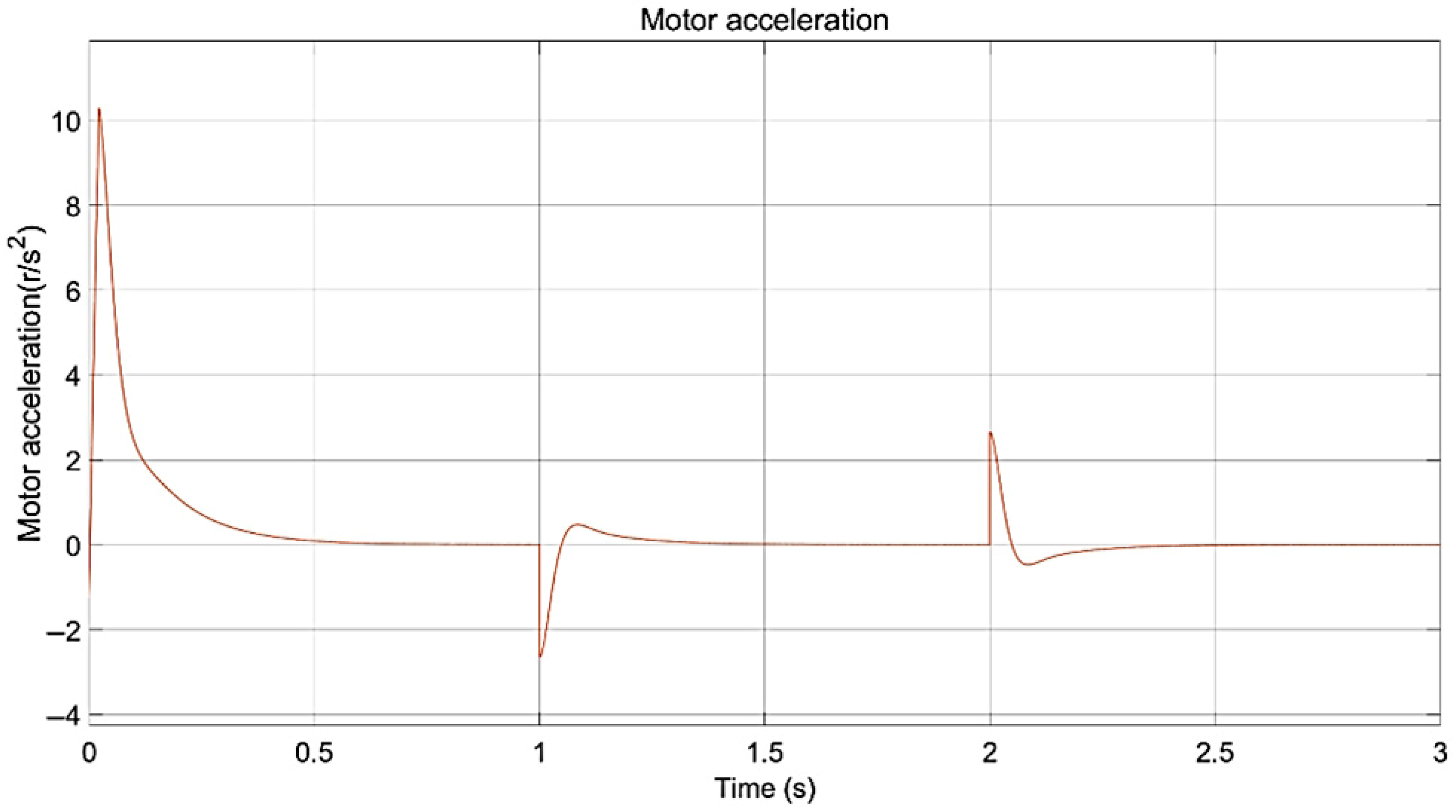
Figure 5 illustrates the acceleration profile of a permanent-magnet synchronous motor (PMSM) as a function of time, with the vertical axis representing acceleration in revolutions per second squared (rev/s
2). During the initial start-up phase, the motor exhibits a rapid acceleration process characterized by a sharp increase to approximately 10 rev/s
2, followed by a subsequent decrease.
This is because the motor needs to quickly reach the set running speed at the initial start-up. In order to achieve rapid acceleration, the control system will apply a larger control voltage, causing the motor to generate a larger electromagnetic torque. The higher electromagnetic torque causes the motor to generate a greater acceleration, allowing the motor to quickly accelerate to close to the set speed. After about 1 s, the acceleration becomes negative due to a sudden increase in load, indicating that the engine undergoes a short deceleration process. The acceleration then tends to zero, indicating that the rate of change of the motor speed becomes very low and the motor approaches a constant speed. At the second second, there is again a small positive peak in acceleration due to the sudden load reduction, after which it quickly returns to zero. Collectively, these transient responses validate the controller’s ability to maintain stability under dynamic mining conditions, including load shocks exceeding 80% of the rated torque. The rapid reversion to zero acceleration after disturbances demonstrates the effective rejection of conveyor-specific perturbations like material surges and belt resonances. This performance is critical in minimizing belt slippage and mechanical stress in high-inertia mining conveyors.
Figure 6 illustrates the variation in the PMSM electromagnetic torque over a period of 3 s, from which it can be seen that the electromagnetic torque of the motor quickly reaches a peak value of about 900 N/m at start-up and then rapidly decreases and tends to a stable value of about 100 N/m for 0.5 s. This is because the motor needs to overcome the inertia of the stationary state and the possible load resistance when starting. In order to enable the motor to start quickly and reach the set operating state, the control system will adjust the current so that the motor generates a larger electromagnetic torque. Critically, the 0.1 s recovery time after load shocks demonstrates superior disturbance rejection compared to conventional methods (0.5 + seconds), validating the ADRC-MPC framework’s efficacy in mining conveyors where sudden load changes exceed 80% rated torque. This performance directly prevents material spillage and reduces belt wear by minimizing speed deviations during disturbances.
The variation in motor torque serves as an indicator of its dynamic response characteristics during both start-up and load changes, demonstrating the stability and adaptability of the motor control system.
In order to verify the advantages of this method compared with other currently used methods, this paper selects four control methods, including PID control, ADRC, extended Kalman filter control, and sliding film control, to compare with the ADRC-MPC method proposed in this paper.
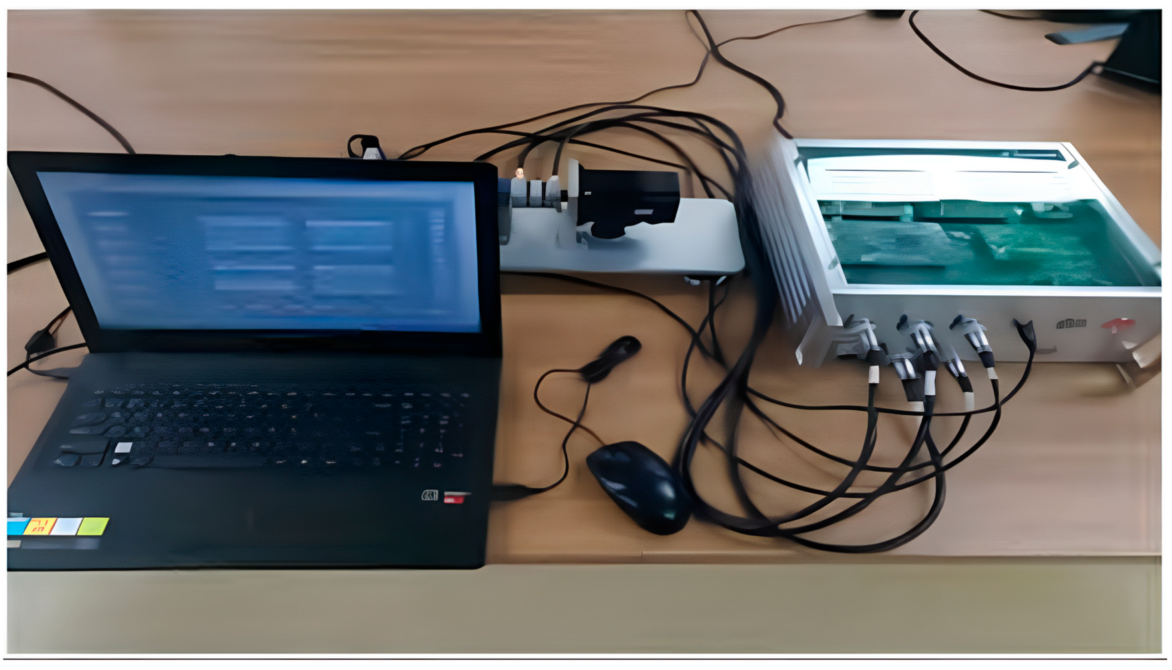
In order to further verify the effectiveness of the model proposed in this paper in actual control and compare it with other methods, a motor test bench consisting of an upper machine, a motor test box, and a PMSM was built.
First, a control system model based on ADRC and MPC was built in the MATLAB/Simulink environment of the upper machine. Then, the model code was generated and compiled through CCS6.2 and input into the motor drive test box. The upper machine was used to collect and process data, and the corresponding experimental results were plotted.
The core component model of the motor drive test box generally consists of several parts: a power analyzer, a dynamometer controller, and a data acquisition system. Power analyzers include Yokogawa WT (company Yokogawa, Japan) series and HBM eDrive test systems. Dynamometer controllers include Magtrol DSP6001 and AVL PUMA 2. Data acquisition systems include HBM QuantumX and NI PXIe systems (
Figure 7).
In the simulation (
Figure 8) we compared five control methods, among which the MPC + ADRC performed the best. The SVC method exhibited the largest overshoot during no-load start-up, and due to the significant overshoot, it also had the longest settling time. When a load was added, the PID + vector control method showed the largest overshoot, with a settling time similar to that of the SVC method. The EKF also had a relatively large overshoot and a long settling time. The ADRC + vector control method and the ADRC + MPC method demonstrated similar settling times and overshoots during no-load start-up, but the ADRC + MPC method achieved a stable state more quickly when a load was applied.
The ADRC + MPC (auto-disturbance rejection control plus model predictive control) method performed exceptionally well in this test. This method only takes about 0.2 s to reach 90% of the target speed in response time, which is significantly faster than other methods. At the same time, ADRC + MPC has almost no overshoot when approaching the target speed, demonstrating extremely high control accuracy. In terms of stability, the curve of ADRC + MPC is very smooth and has almost no fluctuations after reaching the target speed, demonstrating excellent anti-interference capabilities. In addition, the steady-state error of ADRC + MPC is almost zero, further demonstrating its advantage in precise control. In summary, the ADRC + MPC method is superior to other control methods in terms of response speed, control accuracy, stability, and steady-state performance.
8. Conclusions
The present study focuses on the mathematical modeling and vector control of permanent-magnet synchronous motors (PMSMs), which are utilized to drive conveyor belts in belt conveyors employed in the mining industry. A detailed mathematical model of a permanent-magnet synchronous motor has been successfully constructed by investigating its performance and operational requirements in specific situations. The article shows various indicators of the model, including load bearing capacity and dynamic response time, and highlights the advantages of ADRC + MPC by comparing it with other control methods.
The transformation of complex models from a three-phase static coordinate system to a two-phase rotating coordinate system is facilitated by coordinate transformations (Clark and Park transformations). This transformation process is pivotal for the analysis and control of motors, as it facilitates the simplification of complex models and enables control.
The paper details the model predictive control (MPC) methodology and the ADRC methodology, which treat the internal nonlinearities and external disturbances of the system as ‘common disturbances’ and observe and compensate them in real time using (ESO) to achieve accurate control over the system.
The MPC optimization objective is achieved based on minimizing the current, tracking error, and control voltage increment in a discrete linear model. The method significantly improves the stability and dynamic response of the system and effectively suppresses current fluctuations by solving the real-time optimization problem to obtain the control voltage. This is especially necessary for belt conveyors used in mines, where stable operation and fast responses to load changes are important in ensuring efficient material handling on the belt conveyor.
(Combining MPC and ADRC allows the motor to respond more quickly and with smaller tracking errors under start–stop, reversing or speed-changing conditions. The motor can also operate stably when there are sudden load changes (such as an industrial robot arm grabbing heavy objects) or grid voltage fluctuations.)
The study establishes a robust theoretical framework for the control of permanent-magnet synchronous motors in the context of belt conveyors in the mining industry. Furthermore, the feasibility of the proposed model is validated through simulation, thereby paving the way for future optimization and practical applications in the mining industry.
This study proposes an innovative MPC-ADRC cascade control strategy, which applies model predictive control (MPC) to the permanent-magnet synchronous motor current loop to achieve high dynamic current tracking and uses active disturbance rejection control (ADRC) in the speed loop to enhance the anti-disturbance capability. Through dynamic coupling design, the speed loop output of ADRC adaptively adjusts the reference command of the MPC current loop to achieve the coordinated optimization of the speed–current dual loop. This scheme combines the fast response characteristics of MPC and the strong robustness of ADRC, effectively solving the contradiction between dynamic performance and anti-disturbance capability in traditional control. Subsequent research will integrate the disturbance observation of ADRC and the feedforward compensation capability of MPC to construct a global disturbance observation–compensation network for nonlinear effects such as the inverter dead zone and magnetic saturation.


