Article

Concept of 3D Antenna Array for Sub-GHz Rotator-Less Small Satellite Ground Stations and Advanced IoT Gateways


Department of Electronics and Information Technology, Faculty of Electrical Engineering, University of West Bohemia, 30100 Pilsen, Czech Republic
*
Author to whom correspondence should be addressed.
Telecom 2025, 6(4), 92; https://doi.org/10.3390/telecom6040092
Submission received: 17 September 2025 / Revised: 6 November 2025 / Accepted: 20 November 2025 / Published: 1 December 2025

Abstract

Phased antenna arrays have revolutionized modern wireless systems by enabling dynamic beamforming, multibeam synthesis, and user tracking to enhance data rates and reduce interferences, yet their reliance on expensive active components (e.g., phase shifters, amplifiers) embedded in antenna array elements limits adoption in cost-sensitive sub-GHz applications. Therefore, the active phased antenna arrays are still considered as high-end technology and primarily designed only for high-frequency bands and demanding applications such as radars and mobile base stations in microwave bands. In contrast, various important radio communication services still operate in sub-GHz bands with no adequate solution for modern antenna systems with beamforming capability. This paper introduces a 3D antenna array with switched-beam or multibeam capability, designed to eliminate mechanical rotators and active circuitry while maintaining all-sky coverage. By integrating collinear radiating elements with a Butler matrix feed network, the proposed 3D array achieves transmit/receive multibeam operation in the 435 MHz amateur satellite band and adjacent 433 MHz ISM band. Simulations demonstrate a design that provides selectable eight beams, enabling horizontal 360° coverage with only one radio connected to the Butler matrix. If eight noncoherent radios are used simultaneously, the proposed antenna array acts as a multibeam all-sky coverage antenna. Innovations in our design include a 3D circular collinear topology combining the broad and adjustable elevation coverage of collinear antennas with azimuthal beam steering, a passive Butler matrix enabling bidirectional transmit/receive multibeam operation, and scalability across sub-GHz bands where collinear antennas dominate (e.g., Lora WAN, trunked radio). Results show sufficient gain, confirming feasibility for low-earth-orbit satellite tracking or long-range IoT backhaul, and maintenance-free beamforming solutions in sub-GHz bands. Given the absence of practical beamforming or multibeam-capable solutions in this frequency band, our novel concept—featuring non-coherent cooperation across multiple ground stations and/or beams—has the potential to fundamentally transform how the growing number of CubeSats in low Earth orbit can be efficiently supported from the ground segment perspective.

1. Introduction

In recent times, satellite communication has emerged as a groundbreaking trend, particularly in less populated areas such as oceans, deserts, mountains, and primeval forests, where terrestrial communication infrastructure is lacking [1]. Modern small satellites can replace it for sensor data gathering in these areas. However, satellite communication systems rely on a network of ground stations that act as gateways between satellites and terrestrial networks to make collected data available for the end users [2]. As the number of small satellites (especially CubeSat class) in space increases, it is necessary to look for effective provision and use of a network of involved ground stations in order to be able to download data through them [3]. Ground stations for small satellites encounter significant challenges that warrant attention. For instance, the quality of received signals plays a pivotal role in the effectiveness (achievable data rate, bit error rate, packet error rate, retransmission rate) of radio communication with small satellites on low Earth orbits and is susceptible to signal degradation due to low transmitted power (typically 30 dBm) and high path losses, as well as signal interferences caused by the close frequency allocation of multiple satellites or close proximity of terrestrial transmitters to the ground stations [4]. The quality of the received signal also varies due to the changing distance between the low Earth orbit satellites and the ground stations. Also, the gateways for terrestrial IoT networks can face similar problems [5]. Beamforming is a key property for overcoming such issues by focusing antenna gain directly toward the target area or offering the possibility to steer the nulls of the radiation pattern toward interference sources.
To address the challenges in satellite communication and base stations, various solutions have been proposed and documented. Enhancements to the effectiveness of satellite communication systems include signal processing techniques, such as adaptive filters, to eliminate undesired signals [6,7]. However, the most direct approach to improve the quality of the received signal at the ground stations or base stations is to increase the antenna gain, increase its directivity, steer its main beam towards the satellites’ (or IoT sensors) position, and/or minimize the antenna gain towards potential sources of interference. In a multipath propagation environment, the movable antenna arrays have also shown superior performance for signal enhancement while reducing radio frequency chains [8].
Improving the signal quality can also be achieved by using highly directional antennas on a mechanical rotator (although this equipment is mechanically complex and extensive, challenging to maintain, and prone to high failure rates) [9] or by employing a large active phased antenna array (which involves expensive radio frontends with phasing circuits) [10]. Our research group also deals with a cooperative reception scheme that was successfully deployed in [11], enabling multiple satellites to share a few ground stations simultaneously and to improve signal quality by achieving noncoherent diversity combining gain. Phased array antennas are widely utilized in 5G for both base station and user equipment to enhance their performance and MIMO (multiple input, multiple output) capability [12]. At the base station, the phased array antenna can be deployed for beamforming, which involves concentrating received power from the direction of the user (boosting the gain) and minimizing the received power from the direction of interference to improve the signal-to-noise ratio (SNR). Current 5G active phased array antennas are often too complex and expensive, primarily designed for use in higher frequency bands only (e.g., 2.6 GHz, 3.5 GHz) due to dimensional constraints, and are not suitable for low-cost communication services in sub-GHz frequency bands, such as IoT (Internet of Things) gateways, small satellite telemetry ground stations, and trunked radio base stations.
Furthermore, in many applications, it is not always necessary to have an arbitrary radiation diagram achieved by active phased antenna arrays. A switchable radiation diagram for several sectors or a multibeam configuration is often sufficient and can be used to simplify antenna arrays [13,14]. Modern planar antenna systems that provide full beamforming in arbitrary directions necessitate large antenna arrays with complex geometry and numerous elements. These elements must be individually excited with precise control over amplitudes and phases, which demands high precision and efficient beamforming [15]. Achieving this requires multiple individual RF signal paths with digitally controlled phase shifters and variable gain amplifiers or attenuators, as well as a complex distribution feed line network to cater to the individual elements. The cost of such antenna systems is considerable, especially when both communication directions (reception and transmission) are needed. This high cost restricts their use to only the most demanding applications, such as radars, the next generation of base stations for cellular networks (4G, 5G, 6G, etc.) [4], or experimental advanced multi-beam ground stations for satellites [16]. A simplified solution based on the use of passive parasitic elements switched via PIN diodes is described in [17], but still in a higher frequency band outside of our interest. Another solution of beamforming implemented using multi-channel coherent SDRs requires very expensive hardware, while solutions based on low-cost SDRs face numerous challenges—particularly in achieving true phase coherence and synchronized processing of IQ samples. This issue is addressed in publication [18].
As a result, most current research in antenna beamforming is focused on the enhancement of planar antenna arrays in higher frequency bands, typically above 2 GHz, which are used in the aforementioned applications.
Our motivation (arising from long-term operation of a traditional small satellite ground station with a mechanical rotator and high-gain Yagi antennas) is to develop a suitable sub-GHz fixed array antenna based on a circular collinear array antenna and use several principles in the following way:
  • Modification of the radiation pattern in the E-plane by applying phase shifts between elementary dipoles of one collinear antenna element to adapt the radiation diagram of the ground station to low/high elevated satellites (or unmanned aerial vehicles, UAVs), alternatively to closer/further placed ground sensors in case of an IoT base station. So, in this context, it covers the ability to form an uptilted or down-tilted radiation diagram with increased gain and directivity in comparison to a single folded dipole antenna.
  • Modification of the radiation pattern in the H-plane by applying phase shifts between several collinear antenna elements formed into a circular array. This adaptation allows the base station’s radiation diagram to cover one of several supported sectors with more enhanced gain and directivity in comparison to a single collinear antenna element.
  • A combination of both principles above to achieve more flexibility in the radiation diagram adaptation in a full 3D plane with 360° horizontal scanning capability.
  • Involving the Butler matrix, software-defined radio, and relay switch for selecting one beam from a predefined set of beams via switched beamforming; alternatively, using more software-defined radios with a Butler matrix to create an antenna with concurrent multiple beams.
  • Involving our published noncoherent post-detection diversity combining [11], originally developed for spatially distributed stations, we use it inside our antenna between several neighboring beams to add an additional gain of diversity signal processing to the own gain of circular collinear array antenna.
This paper is organized as follows: Section 2 provides a description of the concept design of a collinear antenna and a circular array of collinear elements for the 435 MHz radio amateur satellite band. Simulations of circular collinear array antenna configurations and simplified synthesis of beams are presented in Section 3. Section 4 shows the involvement of the Butler matrix used as a feeding network for our concept of a collinear antenna array to enable an all-sky concurrent multibeam solution of a satellite ground station or simplified switched beamforming for an IoT gateway. Several case scenarios of usage for the proposed beamforming in a collinear antenna array and their advantages are described in Section 5. Section 6 offers additional comments on the different concepts proposed in this paper. Finally, Section 7 offers a brief conclusion of our work and future goals.

2. Collinear Array Antenna Usage and Design

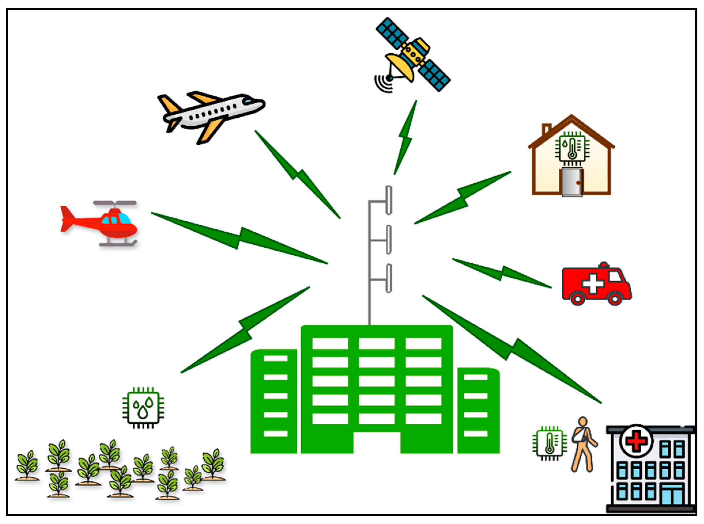
A collinear array antenna is a configuration that consists of two or more fundamental antennas, typically half-wave dipoles or folded dipoles. These fundamental antennas are positioned in such a way that their corresponding elements are parallel and collinear, arranged along a common line or axis. Collinear array antennas have significant applications in various radio communication services, especially in scenarios that depend on base station cellular topologies. These applications include IoT networks (smart buildings, smart cities, agriculture, intelligent transportation systems, telemedicine, etc.), emergency service communication systems (e.g., police, firefighters, emergency medical services), air traffic control, satellite reception (e.g., meteorological satellites), and even more (Figure 1).
All these systems require omnidirectional coverage around the base station and typically operate within lower frequency bands, often below 1 GHz. One of the primary advantages of collinear array antennas lies in their ability to offer omnidirectional coverage in the H-plane and to modify the E-plane radiation pattern in accordance with the target application (ground or airspace coverage). This capability allows for achieving higher antenna gain and customizing the E-plane tilt of the radiation pattern to meet specific operational requirements. For example, the radiation pattern can be tilted downwards (down-tilted) for ground-based operations, upwards (up-tilted) for applications involving aeronautical or unmanned aerial vehicles, or even for satellite operations.
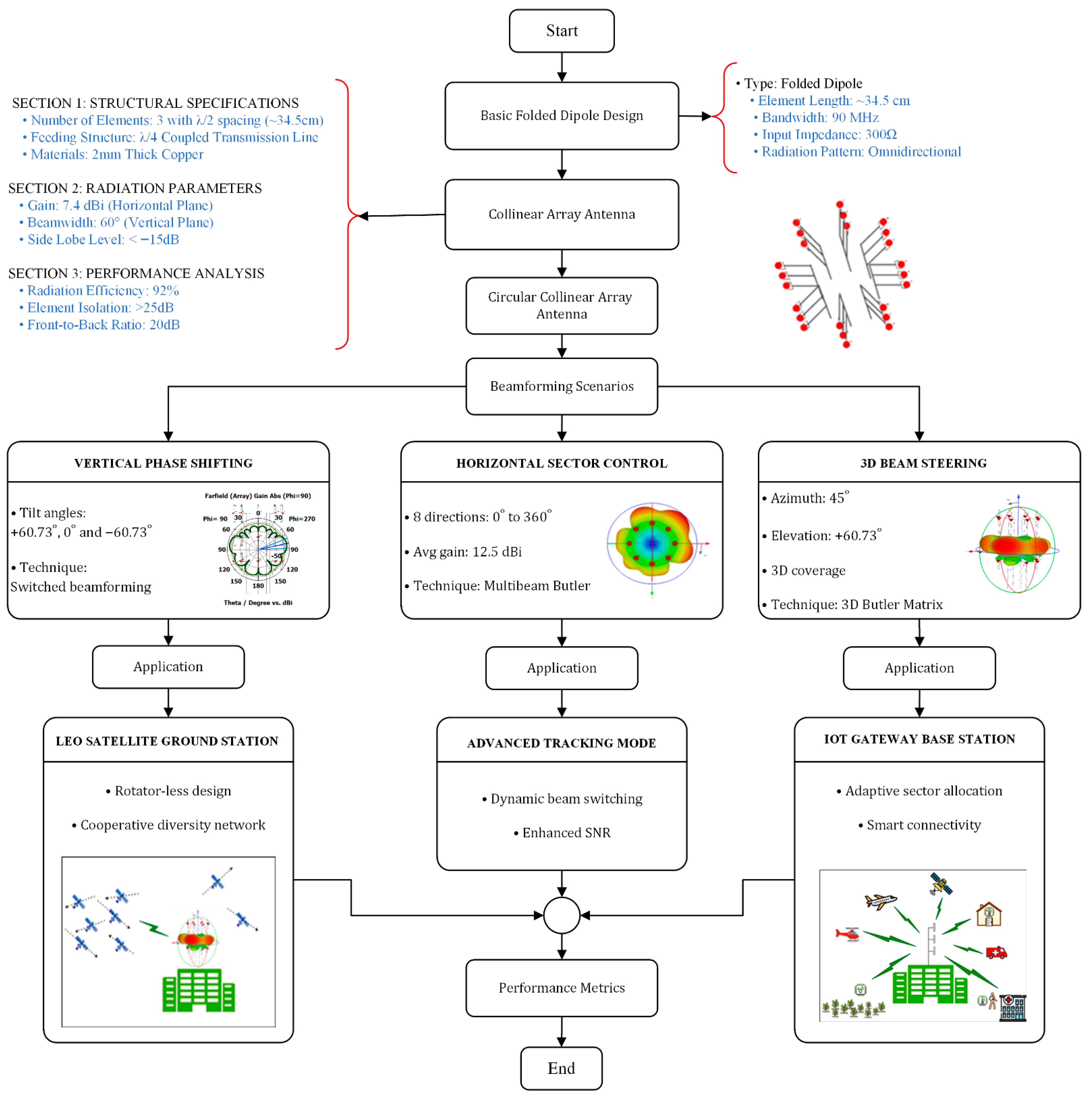
In our research, which focuses on leveraging symmetrical properties in circular antenna arrays for simplified beamforming, we propose a three-step approach. Firstly, we designed the basic folded dipole element targeted for the frequency band and service of our main interest (radio-amateur satellite communication band 435 MHz, ISM band 433 MHz). Secondly, we designed a single collinear antenna consisting of three folded dipoles to increase the gain and directivity in the E-plane. And thirdly, we used it as the fundamental unit within larger circular arrays of collinear antennas for an additional increase in the gain and directivity, also in the H-plane. To provide a clear overview of the paper’s structure, a flowchart has been developed. It illustrates the flowchart of the study, starting with antenna design, followed by beamforming techniques, and concluding with simulation results, as shown in Figure 2.

2.1. Basic Folded Dipole Design

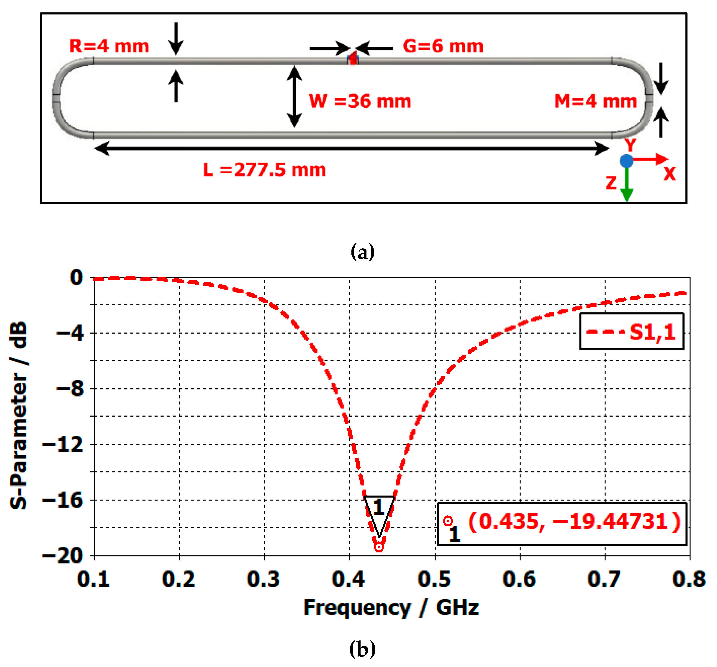
In order to address size and bandwidth limitations, a folded dipole antenna has been designed and modeled in CST Studio Suite to operate at 435 MHz [2]. Utilizing standard equations and conducting a parametric sweep in CST, Figure 3 illustrates the geometrical shape of the basic folded dipole antenna and its impedance matching (return loss).
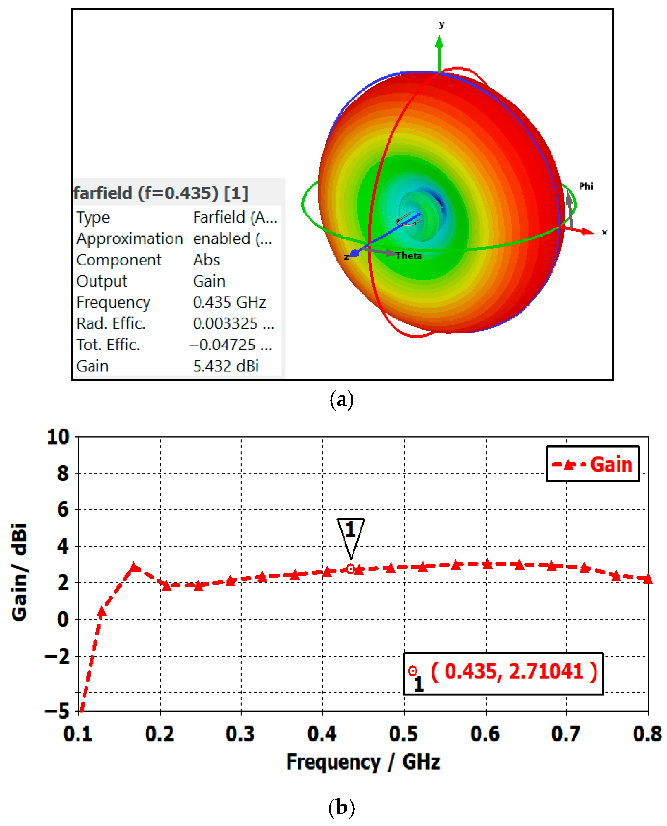
It demonstrates the good performance of this antenna at 435 MHz, which corresponds to the UHF radio amateur satellite band, with an S11 magnitude of −19.44 dB. Additionally, the antenna exhibits still acceptable properties within a broader bandwidth of 90 MHz. The omnidirectional radiation pattern of the proposed antenna in H-plane and a gain of 2.71 dBi at the target frequency are depicted in Figure 4.

2.2. The Geometrical Shape of Collinear Array Antenna

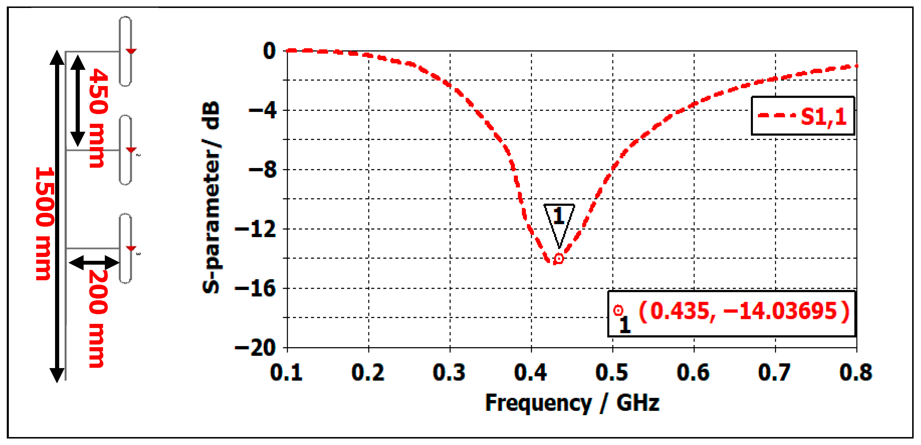
The next step involves creating a collinear antenna by arranging three of the proposed folded antennas in an array structure. These elements are spaced apart from each other in a straight line, with distances carefully optimized to minimize mutual coupling between them. Moreover, each antenna in the three-element collinear array is fed separately using coaxial cables with the appropriate phase applied. A T-junction power divider ensures equal-amplitude, in-phase excitation across the elements, while equal-length coaxial cables preserve phase uniformity along the stack. The mechanical arrangement of the collinear antenna and its S11 graph are provided in Figure 5. This antenna still works well at the desired frequency 435 MHz, and it has acceptable S11 (−10 dB and better) starting from 390 MHz to 480 MHz, which is attributed to optimized separation between elements.
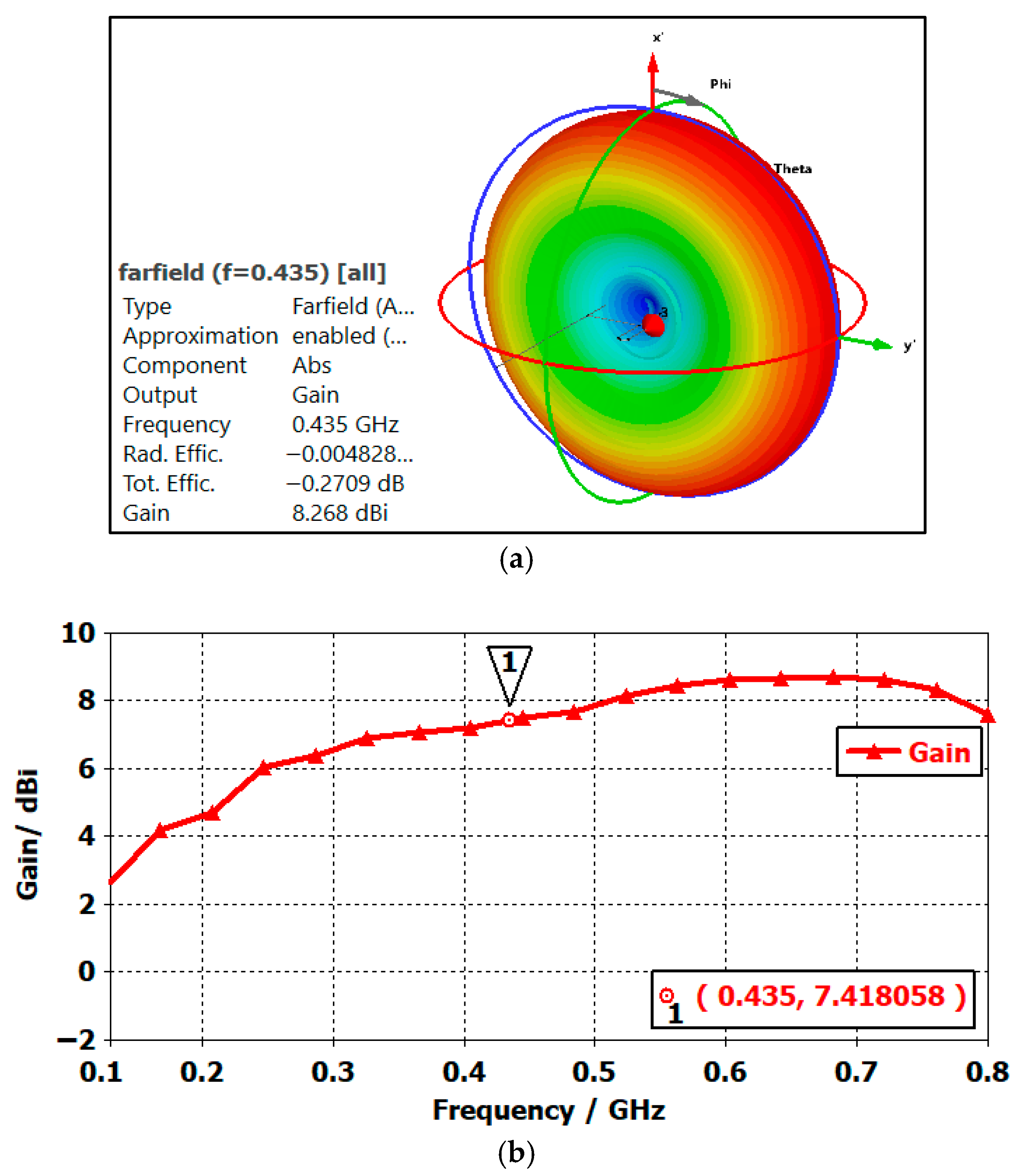
Figure 6 illustrates the three-dimensional radiation pattern of the collinear array antenna, with the main lobe having an increased gain of 7.4 dBi. In comparison to the basic folded antenna, this represents a substantial gain increase, rising from 2.71 dBi to 7.4 dBi, which is a notable achievement in array antennas. Additionally, the side lobes, representing radiation in other directions for the collinear array, exhibit a relatively low magnitude, so side lobe suppression is approximately −34.8 dB. The higher achieved gain allows communication with sensors for extended distances, respectively, improved signal-to-noise ratio (signal quality), and bit error rate performance of radio transmission in satellite communications. However, it is important to note that the higher gain of antennas also leads to more directional characteristics (in our case, in the E-plane) and requires alignment (up-tilting or down-tilting) for optimal performance.
To achieve the desired angles for uptilting (optimized for satellite signal receiving) and down-tilting (optimized for ground sensor signal receiving), the largest phase shift (Δφ) is calculated using Equation (1). In this study, +15° uptilting and −15° down-tilting of the radiation diagram are considered, and phase shifts are calculated to obtain the expected radiation pattern directions.
Δ φ = 2 π × d × s i n   Θ s   λ
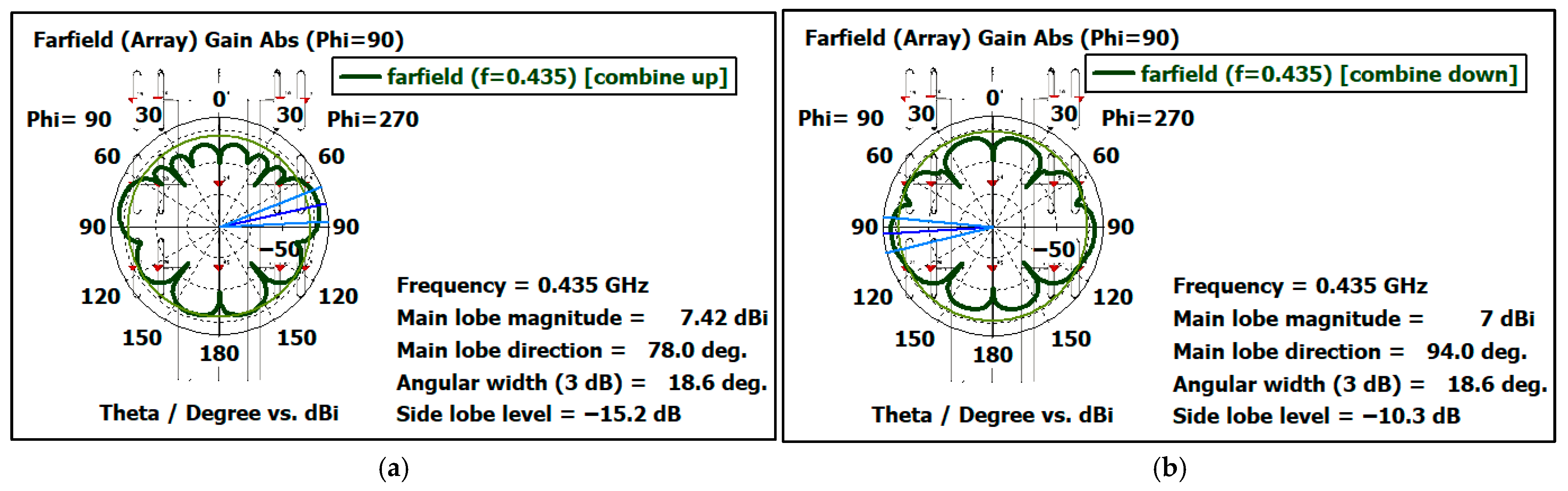
In Equation (1), Δφ represents the phase shift between elements, with d denoting the distance between the folded dipole elements, which is set to 450 mm. Additionally, Θs stands for beam steering, which is +15° and −15° mentioned above. By substituting these parameters into Equation (1), the calculated value for Δφ is found to be approximately 60.73°. The radiation patterns can be uptilted or down-tilted by applying this value of phase shifts between individual dipoles in the collinear antenna, as presented in Figure 7, respectively.

2.3. Circular Array Antenna

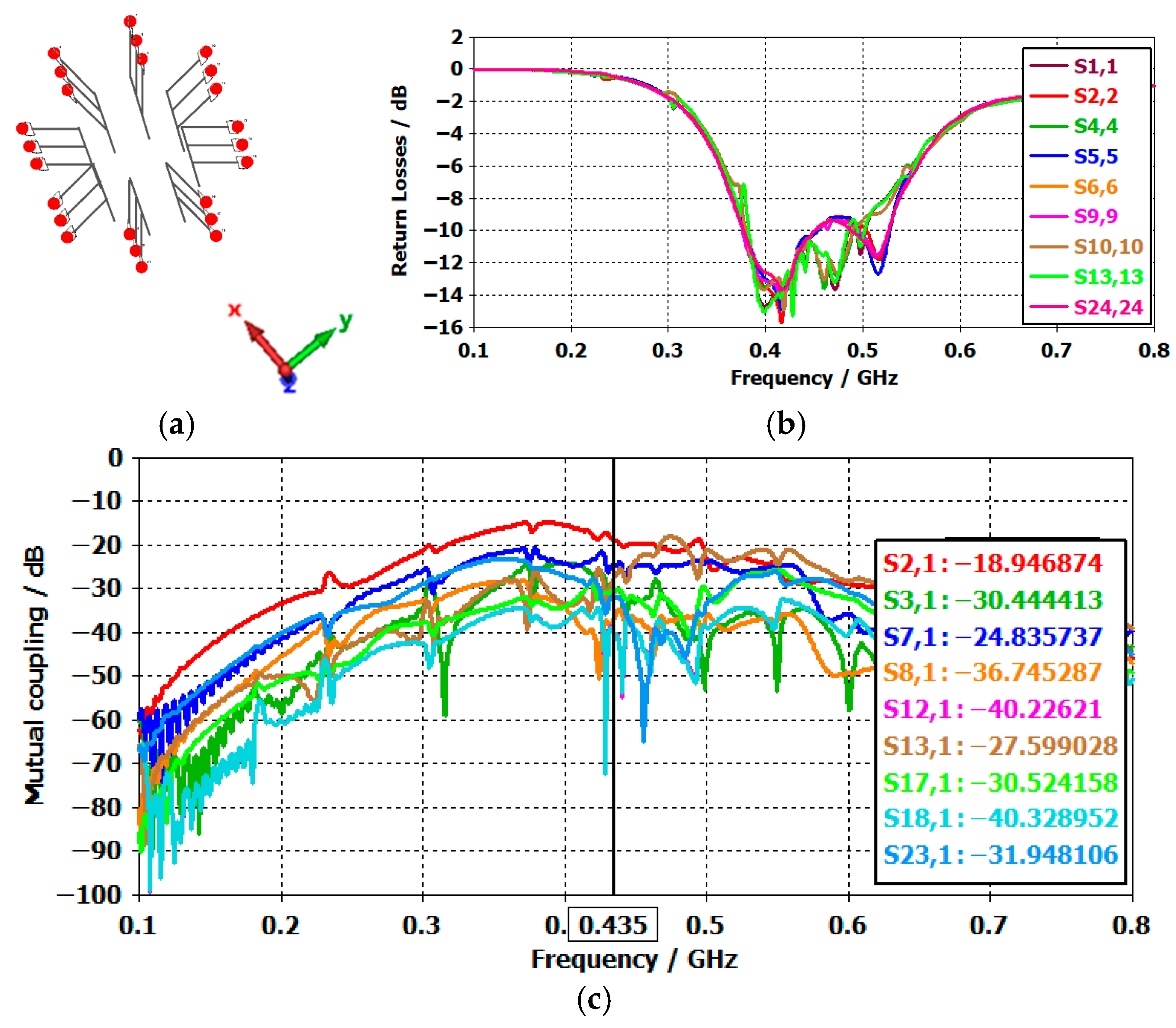
A circular array antenna, consisting of 8 identical collinear elements previously described in Section 2.2 of this chapter, is arranged in a circular pattern with a radius of λ, as shown in Figure 8a. In fact, the spacing between the elements is a critical parameter, as it determines how much the elements affect each other, a phenomenon known as mutual coupling. This spacing represents a trade-off between array size and mutual coupling—reducing the spacing increases coupling, while increasing the spacing reduces it. However, in this work, the author has spaced the elements λ apart to ensure an optimized beamforming process. This type of array arrangement possesses the capability to generate horizontal directional radiation patterns with increased gain, which can be electronically steered in H-plane by adjusting the phase and amplitude of the signal between each element. This makes it suitable for applications such as tracking unmanned aerial vehicles and satellites, where the antenna needs to follow moving targets, or serving as a base station for a network of sensors, where the antenna must sequentially target the sensors placed in different sectors. To prevent mutual coupling between the elements, it is essential to maintain a spacing of at least a quarter wavelength.
Figure 8b presents the reflection coefficient versus frequency of the circular array antenna, while, the mutual coupling depicted in Figure 8c. It is obvious that the maximum value of return losses (represented by S21) is less than −18.9 dB.
In the following section, the idea of switched beamforming in the circular array antenna is introduced. It uses symmetries in a circular array to steer the radiation diagram into symmetrically spaced sectors for simplification of phasing and feeding networks (e.g., using a combination of a Butler matrix and coherent multichannel software-defined radio).

3. Synthesis of Beams in Circular Collinear Array Antenna

To achieve a higher gain than a simple collinear antenna, for better variability of the radiation diagrams, and to maintain the simplicity of the technical solution, only step phase shifts in several discrete values are applied to the circular array antenna through switched beamforming. Omitting the adjustment of the amplitudes of the excitation signals into individual parts of the series makes it impossible to optimize the side lobes of the radiation characteristic, but it leads to a considerable simplification of the excitation network without attenuator elements or programmable amplifiers. Discrete values of phase shifts can be effectively implemented in the future by using a combination of Butler’s matrix and multi-channel software-defined radios with switchable ports, without the need for programmable phase shifters. Due to the symmetry of the circular series, this method of switched beamforming provides sufficient results for the considered application scenarios.

3.1. Phase Shifting for Up-, Down-, and Zero-Tilted Omnidirectional Radiation Diagram

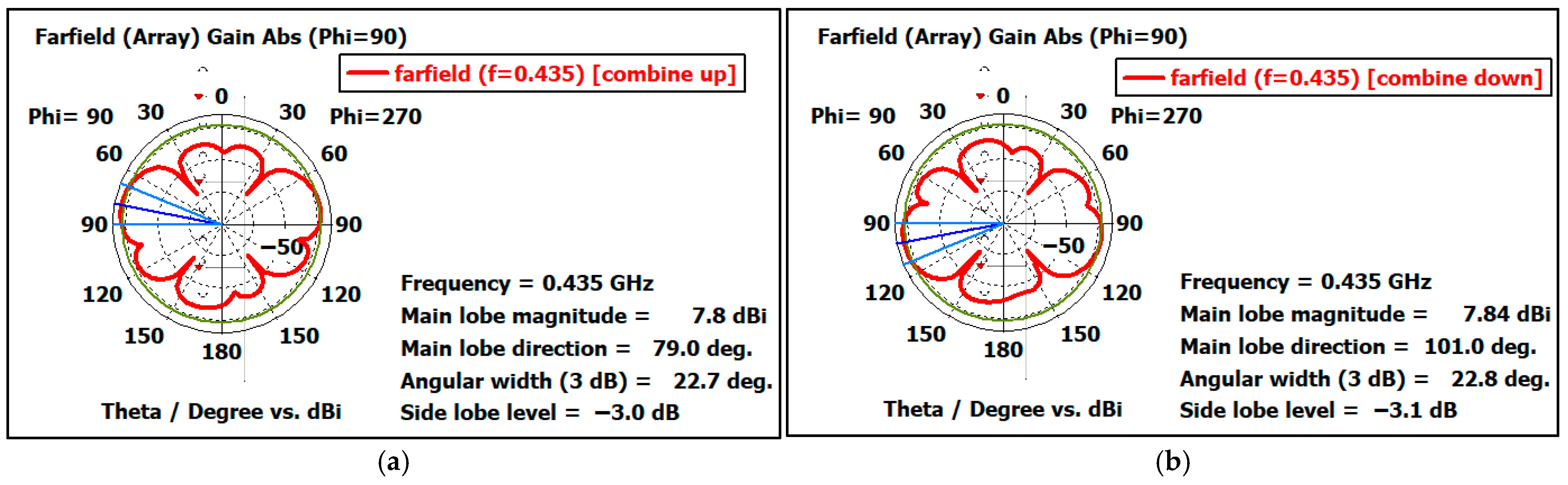
Similarly, as in a single collinear antenna, for the circular array, the phase shifts are applied between elements of the collinear antenna in the E-plane to achieve radiation pattern modifications for up-tilting, down-tilting, and 0° tilt. In this case, phase shifts are applied between the three folded dipoles inside each collinear antenna, while ensuring that all collinear antennas have the same relative phase shift to maintain an omnidirectional horizontal radiation pattern. It is important to note that the calculated phase shift angle Δφ = 60.73° from (1) remains valid in this context. Thus, three discrete values of vertical tilting can be achieved with relative phase shifts between individual stacked dipoles in a collinear antenna, namely (0°, +60.73°, +121.46°), (+121.46°, +60.73°, 0°), and (0°, 0°, 0°), respectively. Figure 9 presents the radiation pattern plots for up-tilting and down-tilting of a circular array antenna.
This mode of operation of the circular antenna array can be used for basic omnidirectional monitoring of ground-based IoT sensors or low Earth orbit (LEO) satellites, as described in the application scenarios in Section 4.

3.2. Phase Shifting for Zero-Tilted Selectable Sector Radiation Diagram

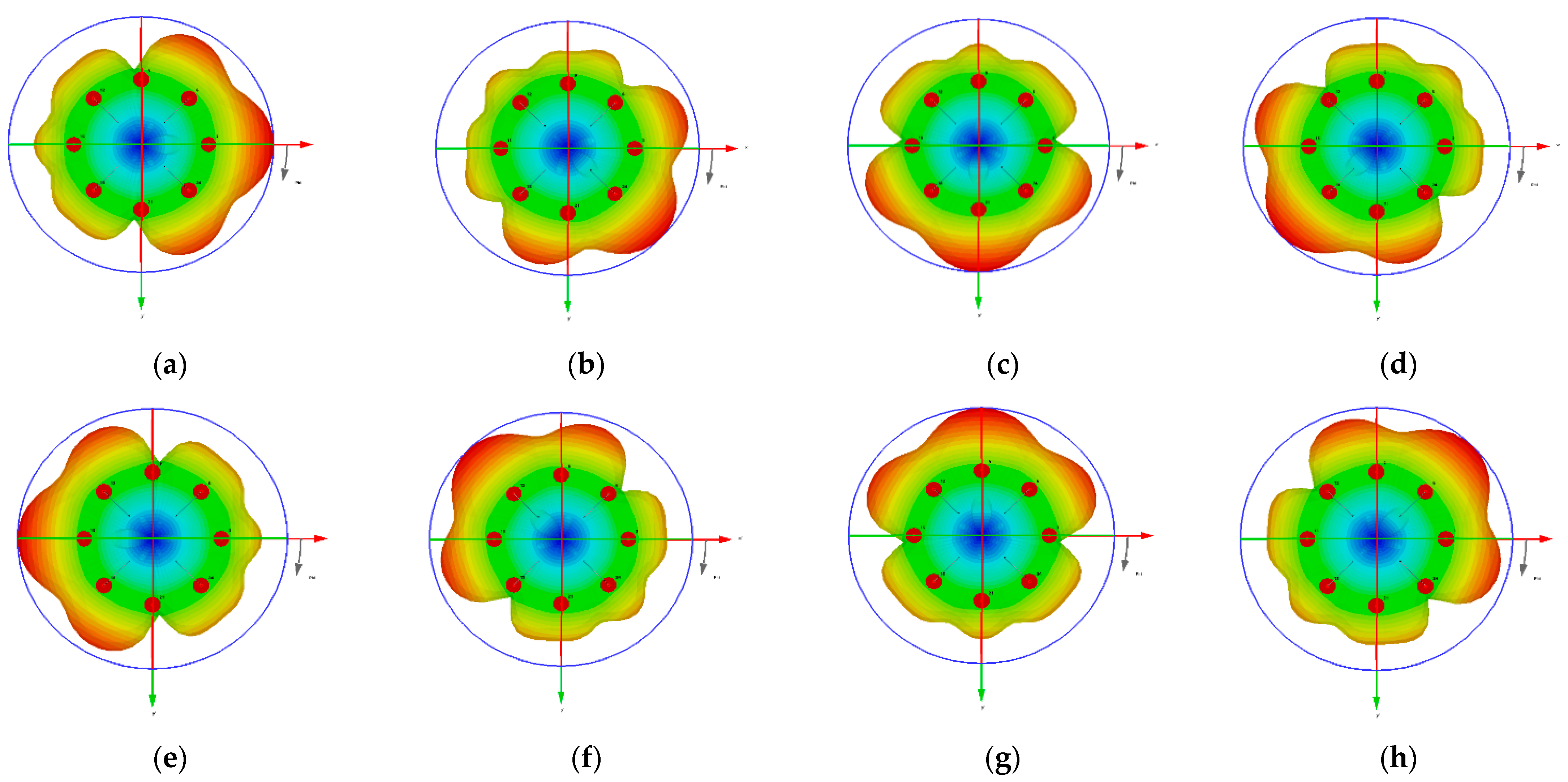
The designed circular antenna array allows for concentrating the radiation pattern horizontally into eight selectable sectors, where phase shifts are applied between 8 collinear elements in the H-plane, resulting in control of the horizontal radiation pattern. For example, if we require eight symmetrical sectors (0°, 45°, 90°, 135°, 180°, 225°, 270°, and 315°) as shown in Figure 10, the calculated relative phase shift angles between collinear elements of the circular array antenna are as follows: 180°, 270°, 90°, 180°, 90°, 270°, 180°, and 90° as presented in Table 1. The radiation pattern of an antenna array can be adjusted to the desired sector only by assigning these few discrete values of the phase shifts in the excitation signals between uniform collinear antennas in a circular array, generally provided by a Butler matrix.
The calculated phase shifts in Table 1 illustrate the advantages of symmetries in a circular array antenna—in our case, with eight elements in the H-plane. In this case, we obtain eight distinct beamformed diagrams, all with approximately the same maximum gain. 12.5 dBi and identical characteristic shapes, achieved by applying only three different values of phase shifts (90°, 180°, and 270°). If we take 90° as the reference input phase of the signal, we need only two discrete values of phase shifters (+90° and +180°). The radiation patterns are presented in Figure 10a–h, and the direction of the main beam is achieved by applying the appropriate shifts (90°, 180°, and 270°) to the inputs of the array ports for all cases, as described in Table 1.

3.3. Phase Shifting for Up- and Down-Tilted Selectable Sector Radiation Diagram

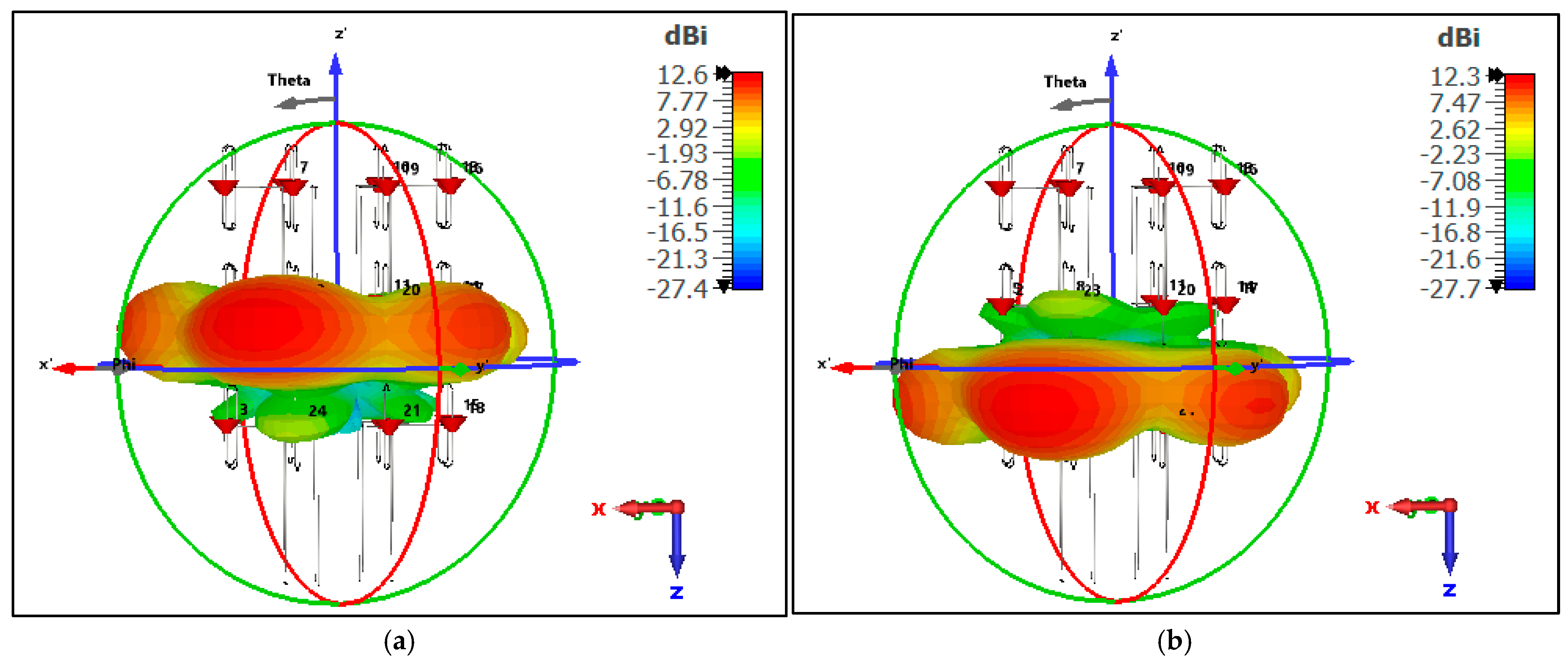
By applying both methods mentioned above (relative phase shifts of 60.73° between folded dipoles in each collinear antenna, together with relative phase shifts of 90° and 180° between collinear antennas in the circular array), it is possible to achieve a variety of radiation patterns with only a limited number of different required phase shifts. These patterns, in our case, can include omnidirectional non-tilted, omnidirectional up-tilted, omnidirectional down-tilted, and 18-sector up- or down-tilted beam configurations. Figure 11 illustrates the up-tilting and down-tilting of the circular array antenna for the horizontal main lobe beam direction of 45°.
This mode of operation of the circular antenna array can be used for increasing the signal quality from ground-based IoT sensors by a down-tilted sector beam or low Earth orbit satellites in higher elevations by an up-tilted sector beam, as described in the application scenarios in Section 5.

3.4. Results of Proposed Circular Array Antenna

As detailed in Table 2 and Table 3, the circular array exhibited an almost uniform gain (approximately 12.5 dBi) of radiation patterns with switched beamforming into specific sectors, and nearly achieved a perfect omnidirectional radiation pattern by applying the same phase of driving signal into all elements.
The circular array also demonstrates a good front-to-back ratio of 7.4 dB in its radiation pattern and bandwidth of 98 MHz related to an accepted S11 scattering parameter equal to or better than −10 dB.

4. Circular Collinear Array Antenna with Butler Matrix Feeding Network

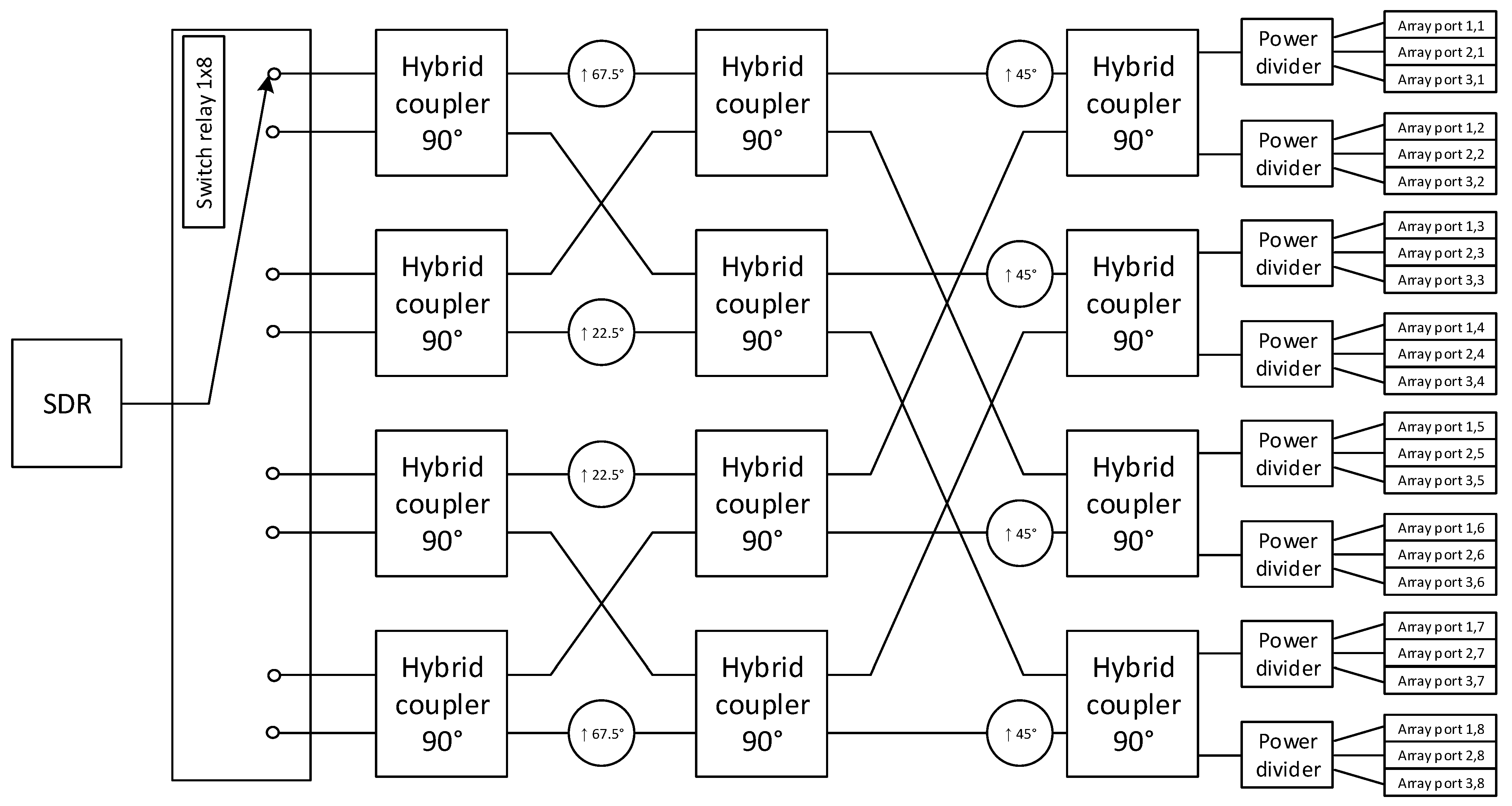
Butler matrix is a well-established form of feeding network for the supplying of antenna elements in an array by an RF signal, commonly used in sector antennas of 4G/5G mobile networks to create several independent beams on different ports of the antenna. Butler matrix consists of hybrid couplers and fixed phase shifters to split and distribute signals from input ports to several output ports with required phase shifts. For a deeper understanding of the Butler matrix and its usage in antennas, we can refer to [19,20,21,22].
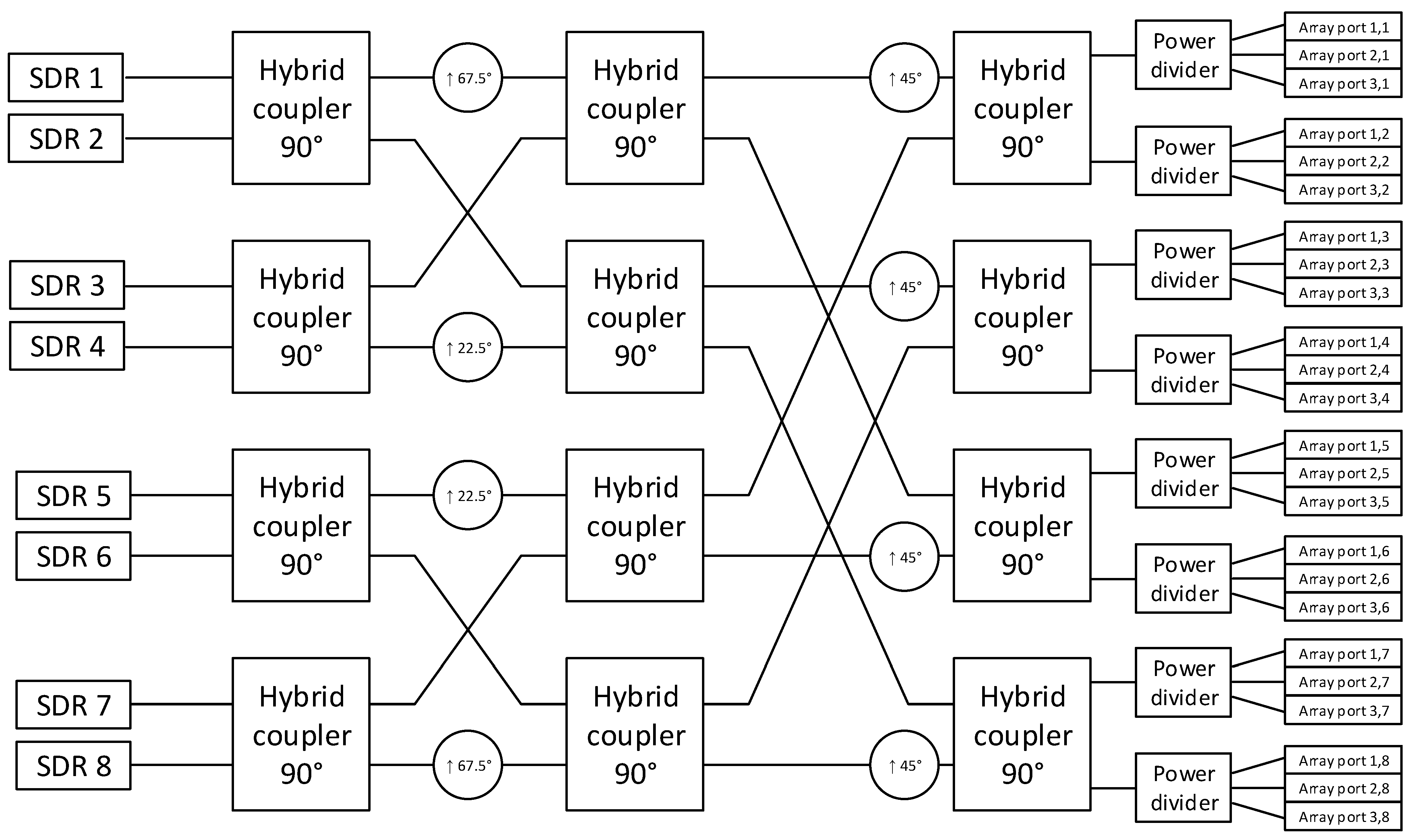
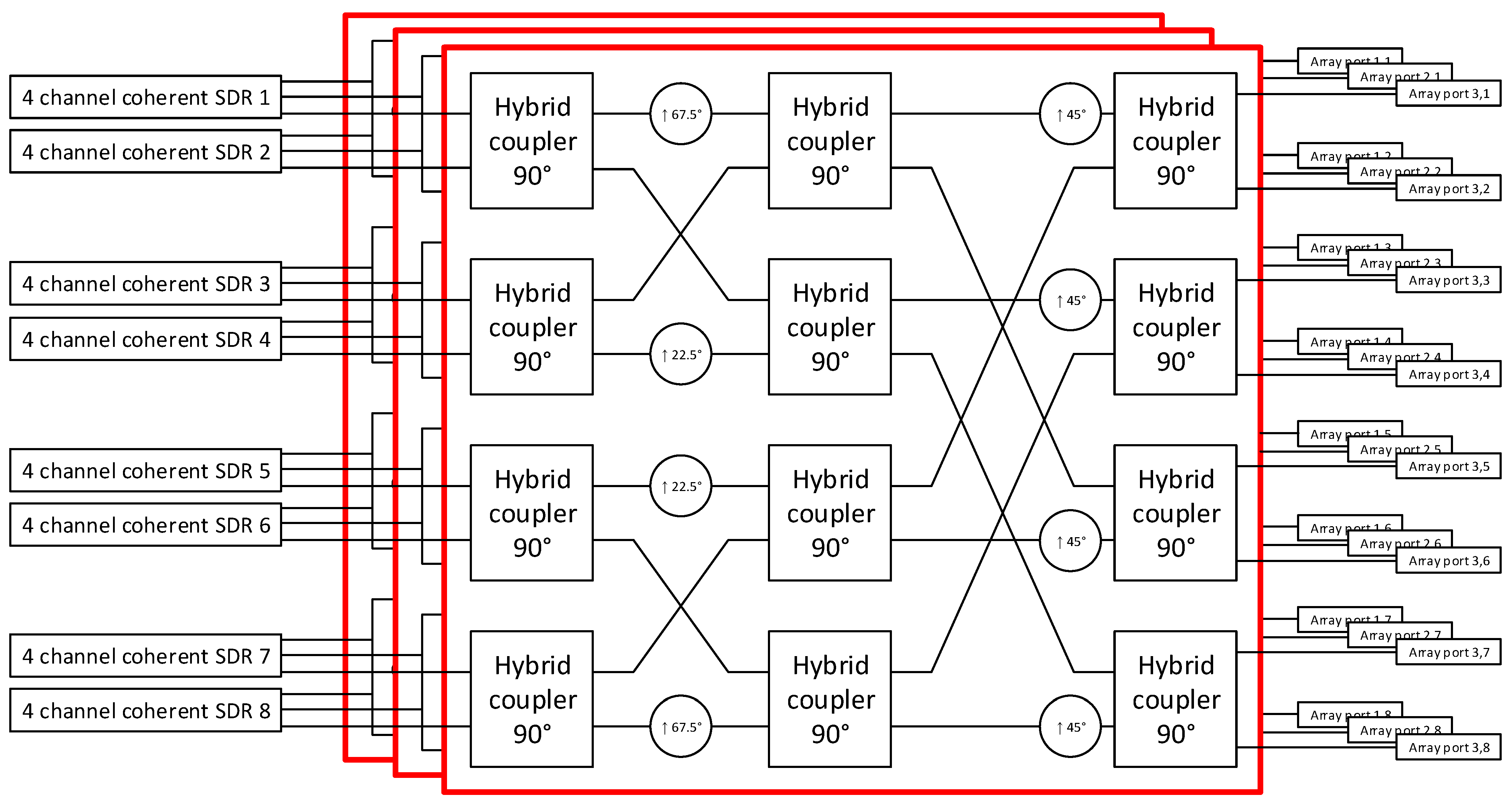
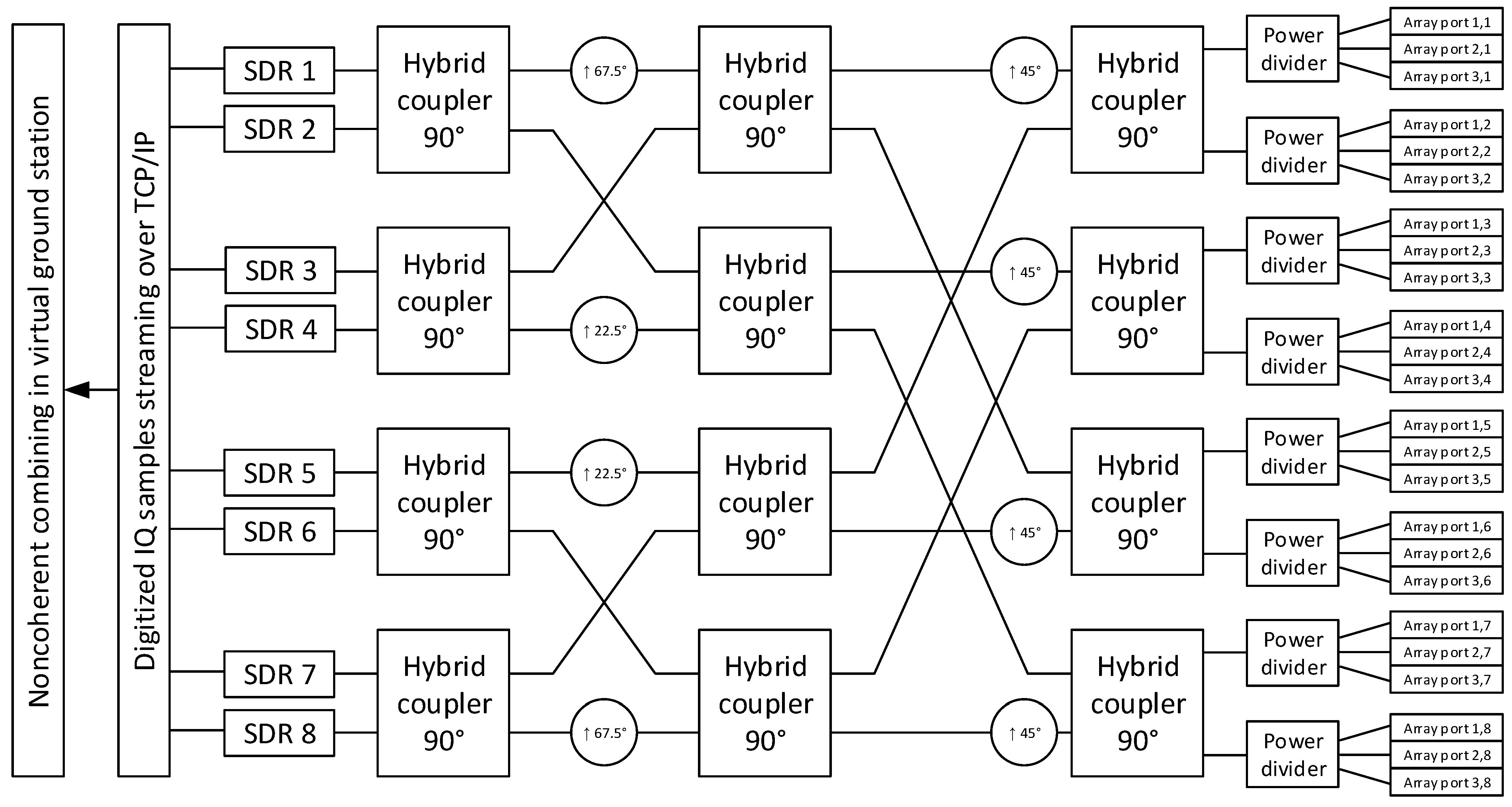
In our work, we are using a conventional 8 × 8 Butler matrix that consists of hybrid couplers between our proposed collinear circular array antenna and software-defined radio(s) (SDR) to fully utilize the array antenna potential in the considered modes of operation and case scenarios. In the following text, several concepts of the mode of operation for the proposed collinear antenna array with a Butler matrix feeding network are described. It covers modes such as sector switched beamforming, sector multibeam, 3D multibeam, and their usage in the virtual ground station concept.

4.1. Sector Switched Beamforming Mode with Butler Matrix

Sector switched beamforming is the simplest and cheapest form of how to achieve a full 360° coverage in H-plane with only one radio, but this full coverage is handled over time by connecting the radio to the proper Butler matrix port via a high-frequency relay switch or a solid-state switch, as presented in Figure 12. It means that, at a given time, only one of the eight predefined beams obtained in Figure 10 is used.
This configuration can be used in the satellite ground station for satellite tracking as the satellite passes through the different sectors of the antenna’s field of view. Alternatively, in an IoT gateway, it can be used for communication with sensors in defined time slots, sector by sector. Vertical tilting is set permanently (for ground operation or aerial operation) by different lengths of cables between power dividers and three antenna array ports in E-plane, causing required phase shifts as described in Section 3.1.

4.2. Sector Multibeam Mode with Butler Matrix

The sector multibeam configuration means that all eight input ports of the Butler matrix are connected to eight software-defined radios Figure 13, so all pre-defined horizontal beams of the collinear circular array antenna are available concurrently, and each radio uses one of them. Therefore, a full 360° coverage in H-plane is achieved at the same time. In E-plane, each collinear antenna element can be optimized by fixed phase shifters (e.g., precisely cut stages of coaxial cables) for an uptilted or down-tilted configuration as the target application requires, as in the previous scenario.
This configuration can be used in the satellite ground station for concurrent satellite tracking across all eight sectors. Alternatively, in an IoT gateway, it can be used for concurrent communication with sensors in different sectors. Vertical tilting is set permanently (for terrestrial operation or aerial operation) by different lengths of cables between power dividers and three antenna array ports in E-plane, causing required phase shifts as described in Section 3.1.

4.3. Multibeam 3D Mode

Multibeam 3D is the most complex configuration, as shown in Figure 14, which enables concurrent processing of eight horizontal beams defined by Butler matrix via eight independent SDRs (same as previous configuration) and also enable independent tilting of each beam via four channels coherent SDRs (three channels used for active supply triplet of Butler Matrix, the fourth channel intended as calibration port).
This configuration can be utilized in the satellite ground station for concurrent satellite tracking across the entire sky, with tilting continuously optimized in each sector via coherent SDR phasing. Alternatively, in an IoT gateway, it can be used for concurrent communication with sensors in different sectors, with tilt optimized as the distribution of sensors actually requires. Vertical tilting can be modified by applying the phase shifts between three identical Butler matrices (down-tilted for terrestrial operation or up-tilted for aerial operation) by phasing in the software domain via multichannel coherent SDR, causing the required phase shifts as described in Section 3.1.

4.4. Noncoherent Receive Diversity Combining Across Different Beams

As our antenna is generally intended for bidirectional (receive/transmit) half duplex communication, only phasing inside a passive Butler matrix is used for horizontal beam synthesis and amplitude tapering is omitted to keep design simple and efficient, because amplitude tapering by controlled attenuators increases a noise temperature and losses, while amplitude tapering by active programmable amplifiers increase cost and complexity as signal path have to be split into Rx and Tx before amplification and merged again after it. However, omitting amplitude tapering leads to significant side lobes of synthesized beams, as shown in Figure 10.
In common communication systems, the side lobes of antennas are unwanted as they decrease the gain of the main lobe of the beam. However, our research team also deals with the idea of a shared reception-only network of cooperating SDR receivers and processing of a large amount of noncoherent copies of the signal captured on spatially distributed remote stations (we call this the virtual ground station principle). In our case these side lobes mean that the satellite signal can be received not only by the one beam pointing into desired sector, but also by other beams as side lobes can be sufficiently strong to receive signal with lower quality and in this scenario our proposed collinear array antenna with Butler matrix and independent SDRs can acts as several nodes for noncoherent combining in virtual ground station (Figure 15). As our study [11] showed, weaker signals can also be constructively used by noncoherent post-detection diversity signal combining to decrease bit error rate and packet error rate, bringing additional gain of diversity combining.
Mathematically, this noncoherent post-detection diversity combining from individual beams received by independent SDRs can be considered as a repetition forward error correction code with majority voting output decision, but without a power penalty caused by bit retransmission, as in our case, the bit retransmission is substituted by parallel signal reception via independent beams of the proposed collinear array antenna with a Butler matrix.

5. Case Scenarios of Collinear Antenna Array Usage

To demonstrate the benefits of even very simplified switched beamforming (with only a few selectable sectors) using a collinear antenna array, we have prepared two possible scenarios of use—rotator-less ground station for monitoring small radio amateur satellites on the low Earth orbits (our main goal) and an adaptable base station for reading data from remote sensors (as future potential of this collinear circular array concept).

5.1. Switched Beamforming in the Ground Stations for Small Low Earth Orbit Radio-Amateur Satellites

In this scenario, a collinear circular antenna array is used in an enhanced rotator-less ground station for the concept of a cooperative diversity network of ground stations [6], dedicated to telemetry download from satellites orbiting in low Earth orbits. The limited gain of the designed circular collinear antenna array from angles at high elevation may seem such as a problem for its use; however, it is necessary to take into account the orbital mechanics and statistics of occurrence of LEO satellites at different elevations and the elevation dependency of free space losses (shorter communication distance in higher elevations).
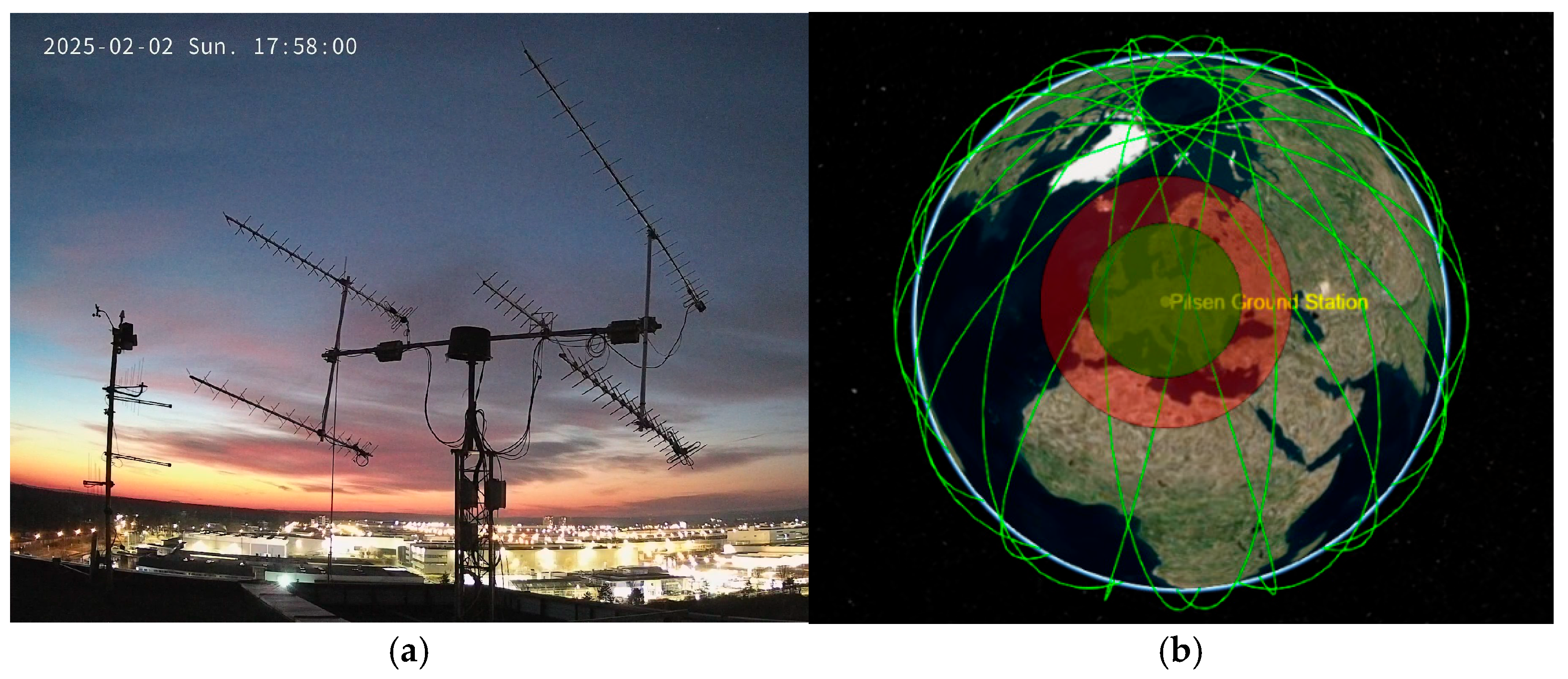
The antenna is primarily intended for communication applications with small CubeSat satellites in the UHF band, where low-speed transmission (e.g., 4800, 9600, 19,200 bps) is primarily used for telemetry due to limited channel bandwidth and limited output power of the satellite radio. Typically, Yagi antennas with a gain of 12–16 dBi are used on rotator ground stations for communication with these CubeSats in this band. However, omnidirectional antennas are occasionally also used, which are suitable for capturing lower rates (1200 or 2400 bps), or even higher rates, but with a high packet error rate. These data can be verified on records from the SatNOGS community network of stations, where both rotator solutions and omnidirectional rotator-free solutions are used. Our group also operates its own long-term ground station in Pilsen with Yagi antennas to keep a bidirectional connection with Czech nanosatellites—VZLUSAT-1 and VZLUSAT-2, as presented in Figure 16. The long-term experiences with the rotator solution and related maintenance/reliability issues inspire us to search for some alternatives. Our proposed antenna array aspires to replace these rotator solutions in ground stations for CubeSats, and we also want to apply it to a network of cooperating stations with non-coherent diversity signal processing, which is discussed in [11].
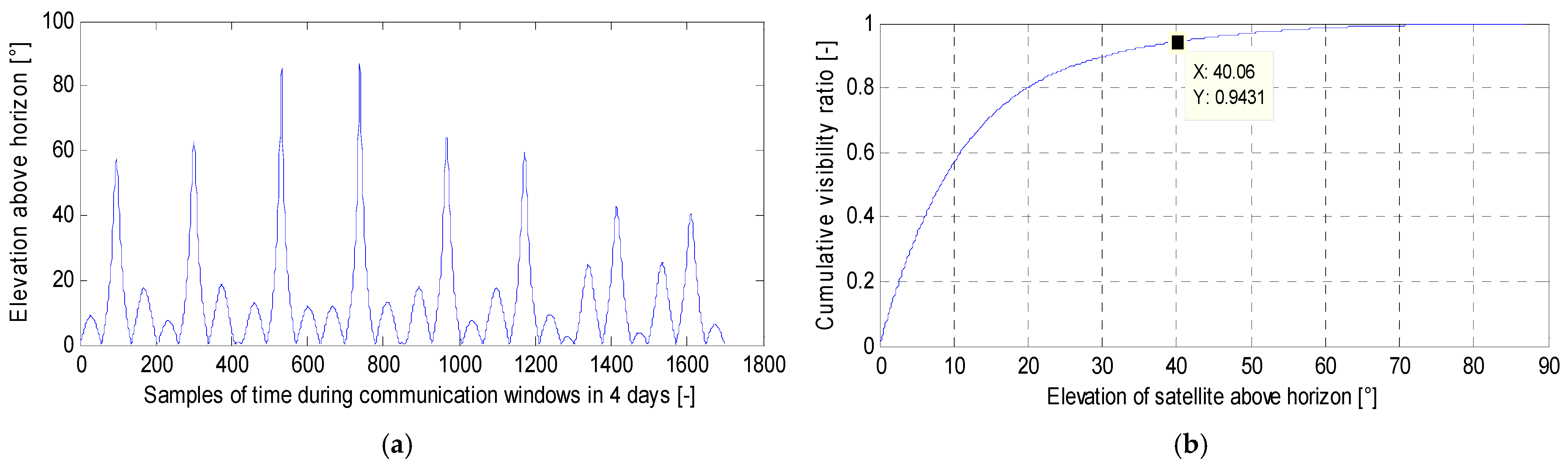
As shown in Figure 16b and Figure 17, LEO satellites pass the ground station only a few times a day, and not every pass is at the maximum possible elevation, e.g., the VZLUSAT-1 satellite passes within range (red circle) of our station in the Czech Republic on average 6 times a day, but only during four passes does the satellite rise above an elevation of 10° (green circle).
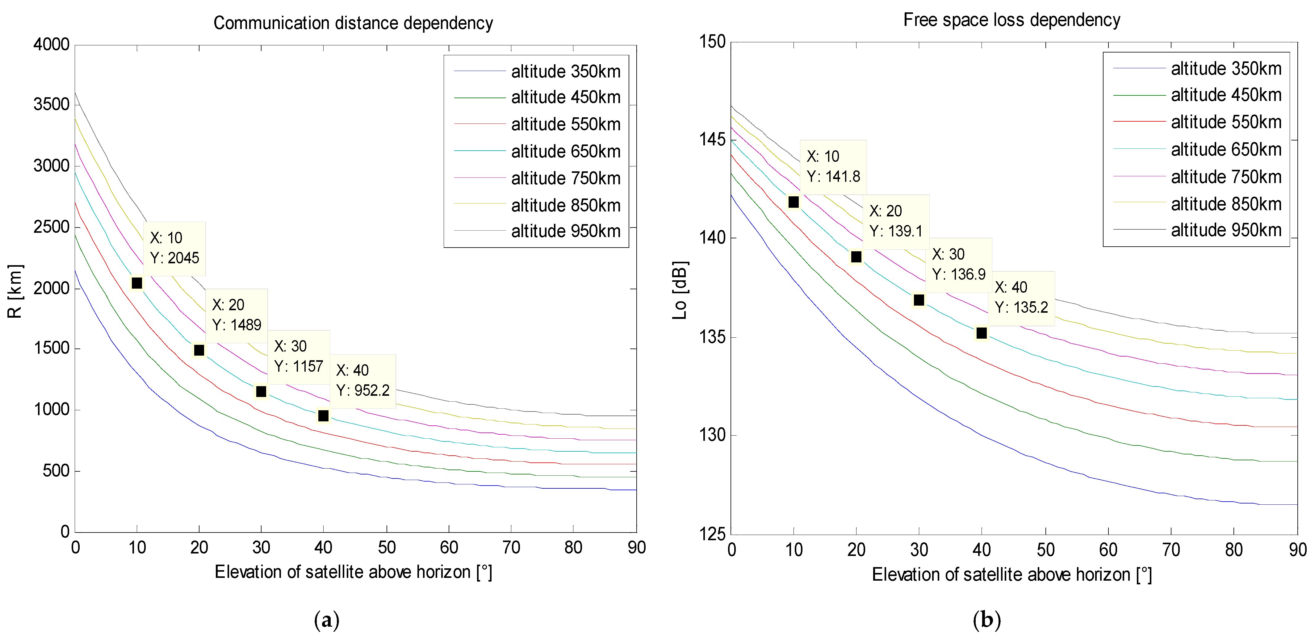
It can be seen from Figure 16b that in this case, the satellite spends 80% of the communication time at an elevation lower than 20° and 94% of the communication time at an elevation lower than 40°. Therefore, it is not important to optimize the gain of the antenna array of the ground station for higher elevations. The ground station can work even with one vertical up-tilting value for maximum simplification of beamforming. From the statistics of satellite passes in the low Earth orbits, it follows that the satellites spend a significant proportion of the communication time only at low elevations relative to the ground station, and if they ascend to higher elevations for a short time, the communication distance is significantly shorter and therefore also the lower free space loss compensates for the lower gain of the antenna at higher elevations. The dependencies of communication distance on elevations are shown in Figure 18a, while the dependencies of free space losses on elevations are shown in Figure 18b. The satellite trajectory predictions are based on the SGP4 algorithm.
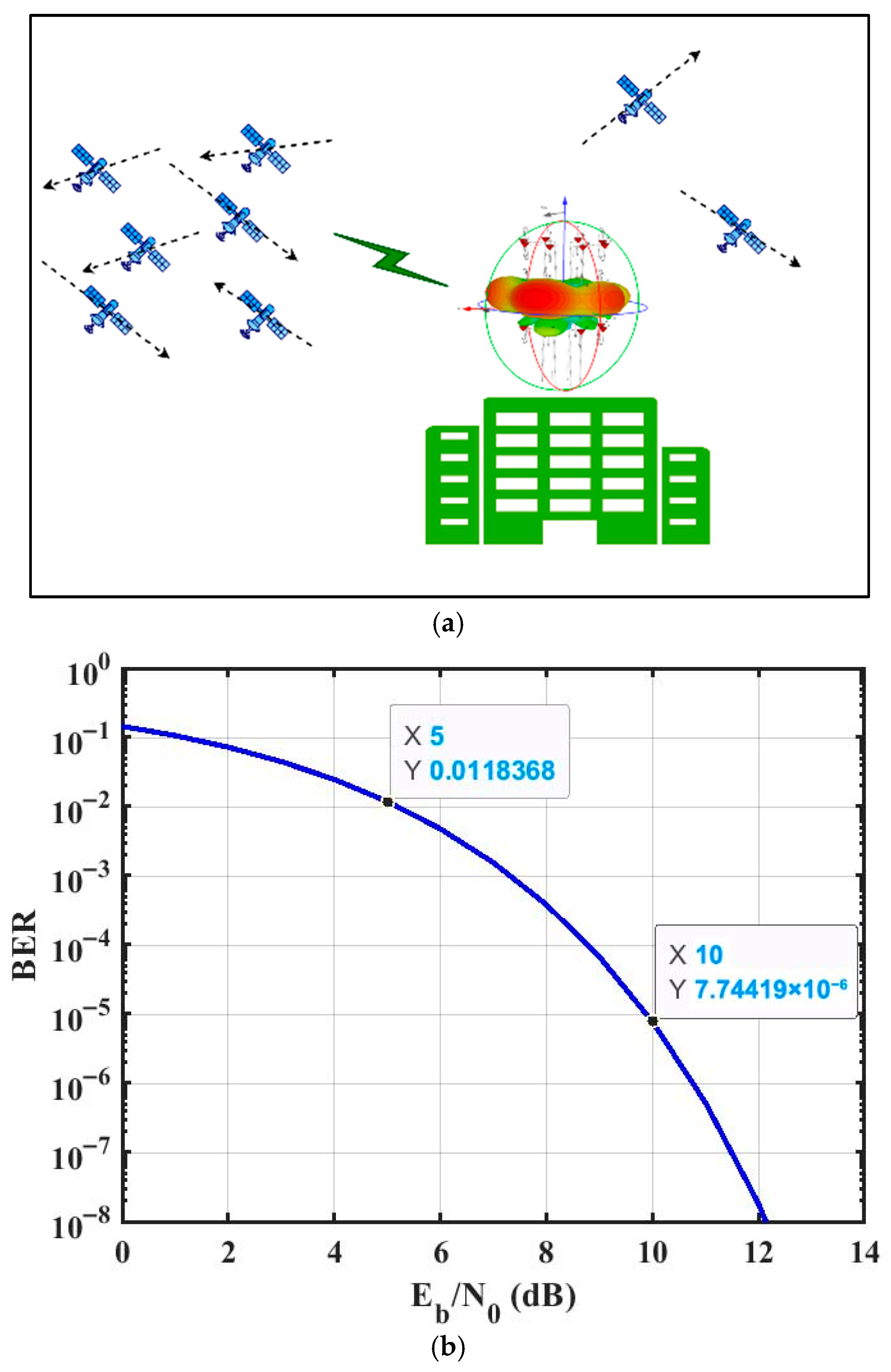
The ground station with our collinear circular array can select reception from one of eight symmetrically spaced sectors with up-tilted (Figure 19a) or zero-tilted radiation diagram. With the selected sector radiation diagram, it achieved a gain of approximately 12.5 dBi, which is an increase of 4.8 dB compared to a single omnidirectional collinear antenna. This increase in gain can be used to increase the bit rate by a factor of three compared to a single omnidirectional collinear antenna, while maintaining the same level of bit error rate. Relations between bit rate (BR), received signal quality expressed as ratio of energy per bit (Eb) per spectral noise density (N0), and power of received carrier (C) are shown in Equation (2).
C N 0 = 10 · l o g 10 E b   · B R N 0  
The increase in gain can also be used to reduce the bit error rate, e.g., from the original bit error rate equal to 10–2 (if an omnidirectional collinear antenna is used) down to 10–6 (if a circular collinear antenna array switched to a selected sector is used), while maintaining the required bit rate. The relation between the bit error rate and the received signal quality is shown in Figure 18b.
Sector selection can be controlled centrally or decentralized based on the highest concentration of monitored satellites in individual sectors, or on the possibilities of other cooperating stations to cover other sectors in which satellites of interest would be located. In case of a requirement to track a large number of satellites from different directions, the station can switch to omnidirectional behavior, and the loss of gain would be compensated by diversity processing gain from the cooperating network of stations, as introduced in our work [11].

5.2. Switched Beamforming in Adaptable IoT Gateway Base Stations

Circular collinear antenna arrays can find great potential in adaptable base stations of IoT networks. Base stations serve as gateways between the network of sensors and superior cloud applications. In particular, the direction of wireless communication from sensors to base stations is limited by the limited performance of IoT sensors, which are often powered only by batteries. Therefore, for high-quality coverage, the network of omnidirectional gateways must have a sufficient area density to ensure a sufficiently strong received signal from power-limited sensors.
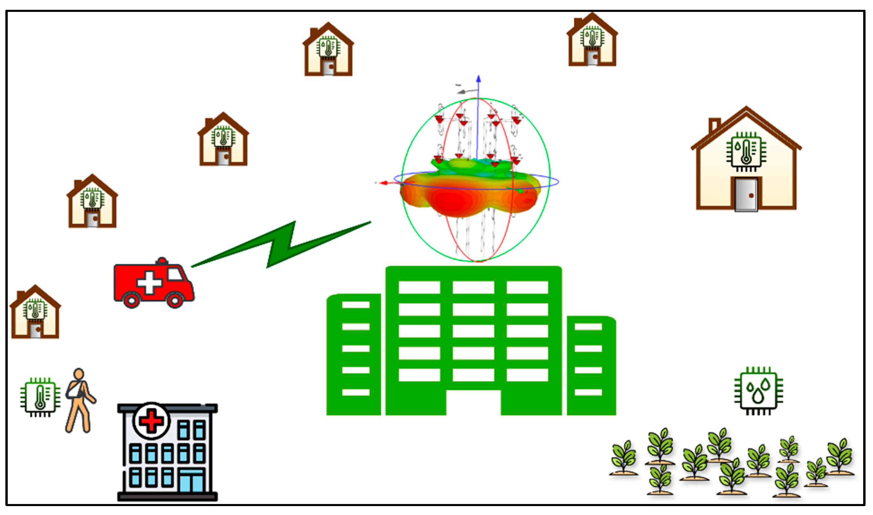
In this scenario, a collinear circular antenna array with switched beamforming is used as an enhanced gateway base station for the IoT sensor network. The station can select reading the data from sensors in eight symmetrically spaced sectors (Figure 20) with an achieved antenna gain of approximately. 12.5 dBi, which is an increase of 4.8 dBi compared to a single omnidirectional collinear antenna. This increase in gain can be used to increase the bit rate by a factor of 3 compared to a single omnidirectional collinear element, while maintaining the bit error rate (see Equation (2)). Alternatively, it can be used to extend the covered area around the base station as increased antenna gain compensates the increased free space path losses, while maintaining the bit rate and bit error rate. Free space path losses (FSPL) of transmitted signals are dependent on the communication distance as:
F S P L = 20 · l o g 10 d + 20 · l o g 10 f 147.55
In Equation (3), the free space path loss results in dB units, the communication distance d is substituted in meters, and the communication frequency f is substituted in Hz. If we can use the increased gain of the antenna array by 4.8 dB, it is possible to increase the free space path loss also by 4.8 dB and thereby extend the communication distance by a factor of 1.7 and cover an area by a factor of three. In this case, three times fewer base stations will be needed to cover the same total area if our circular collinear array with switched sector beamforming is used instead of an omnidirectional collinear antenna.
Sector selection can be controlled sequentially to communicate with sensors over time, sequentially, sector by sector; in case of a requirement to communicate with a large number of sensors in different directions at the same time (e.g., sending the group commands for all sensors).

6. Additional Comments to Possible Solutions

Table 4 lists a comparison of the proposed work with the previous studies’ review of the type of antenna, bandwidth, operation frequency, size, and intended application. However, we were unable to identify any comparable multibeam or beamforming-capable solutions operating below 1 GHz, confirming that such approaches are notably absent in this frequency range—unlike higher bands, where numerous implementations exist. Our proposed antenna array introduces several modes of operation, depending on the availability and affordability of multichannel coherent SDRs. Given that achieving coherent processing with low-cost SDRs presents significant challenges [18], we also propose an alternative approach: combining a simplified version of our ground station with the principle of non-coherent signal combining, as demonstrated in our previous research [11], to enhance overall performance. The advantages and limitations of these operational modes are summarized in Table 5.
For example, the growing number of CubeSats in low Earth orbit can be effectively managed in the future through the deployment of our proposed sector multibeam mode. In this configuration, a single ground station is capable of simultaneously receiving signals from multiple satellites located in different sectors across the entire digitized amateur radio band for satellite communication (435–438 MHz), all within a cost-effective solution. While the absence of vertical tilt adjustment may result in some antenna gain loss, this can be compensated for by non-coherent signal combining from multiple similar ground stations operating within a cooperative network, similar in principle to the existing SatNOGS community infrastructure, which is still missing a cooperative mode with signal combining.

7. Conclusions

In this study, we have focused on the use of collinear antennas as key elements in a larger circular array, specifically designed for rotator-less satellite ground stations operating in the 435 MHz band. However, the same concept is applicable to gateway base stations in IoT networks operating within the sub-GHz frequency band. We have demonstrated the potential of achieving switched beamforming with a limited number of phase shifts required by the array elements, significantly simplifying the feeding networks and eliminating the need for complex radio-frequency frontends. This reduction in the number of required phase shifts stems from the inherent symmetries of the circular array structure. The proposed array, utilizing collinear elements, can dynamically switch radiation patterns between up-tilted, down-tilted, and zero-tilted configurations. This capability makes it highly suitable for weak signal reception from radio amateur satellites in the 435 MHz band, without the need for mechanical antenna rotators, or for sector-based sensor readings in the ISM 433 MHz sector. For example, by applying three different phase shifts (reference phase, +90°, and +180°) across the array elements, the radiation pattern can be switched to seven distinct shapes, resulting in main lobe directions at 0°, 45°, 90°, 135°, 180°, 225°, 270°, and 315°, as well as an omnidirectional pattern. In our forthcoming work, we will focus on the effective implementation of array antenna excitation for switched beamforming. We aim to achieve this using low-cost consumer-grade software-defined radios with a limited number of coherent channels (typically 2 or 4), combined with a fixed Butler matrix. This simplified architecture offers great potential for various applications, including serving as a base station for IoT networks or emergency communication systems.

Author Contributions

Conceptualization, M.J. and I.V.; methodology, M.J.; investigation, M.J. and I.V.; resources, M.J. and I.V.; writing—review and editing, M.J. and I.V. All authors have read and agreed to the published version of the manuscript.

Funding

This work was supported by University of West Bohemia, Pilsen, under the Project Name: SGS-2024-005.

Data Availability Statement

The original contributions presented in this study are included in the article. Further inquiries can be directed to the corresponding author.

Conflicts of Interest

The authors declare no conflicts of interest.

References

  1. Centenaro, M.; Costa, C.E.; Granelli, F.; Sacchi, C.; Vangelista, L. A survey on technologies, standards and open challenges in satellite IoT. IEEE Commun. Surv. Tutor. 2021, 23, 1693–1720. [Google Scholar] [CrossRef]
  2. Maral, G.; Bousquet, M.; Sun, Z. Satellite Communications Systems: Systems, Techniques and Technology; John Wiley & Sons: Hoboken, NJ, USA, 2020. [Google Scholar]
  3. He, G.; Gao, X.; Sun, L.; Zhang, R.J.I.A. A review of multibeam phased array antennas as LEO satellite constellation ground station. IEEE Access 2021, 9, 147142–147154. [Google Scholar] [CrossRef]
  4. Sabban, A. Advanced Radio Frequency Antennas for Modern Communication and Medical Systems; BoD–Books on Demand: Norderstedt, Germany, 2020. [Google Scholar]
  5. Petroni, A.; Biagi, M. Interference mitigation and decoding through gateway diversity in LoRaWAN. IEEE Trans. Wirel. Commun. 2022, 21, 9068–9081. [Google Scholar] [CrossRef]
  6. Jahanbakhshi, M.; Hayati, M.; Vertat, I. Prototype of compact Microstrip lowpass filter for active phased antenna array with ultra-wide stopband using funnel shaped resonator. In Proceedings of the 2022 International Conference on Applied Electronics (AE), Pilsen, Czech Republic, 6–7 September 2022; pp. 1–4. [Google Scholar]
  7. Alnahwi, F.M.; Al-Yasir, Y.I.A.; Abdulhameed, A.A.; Abdullah, A.S.; Abd-Alhameed, R.A. A Low-Cost Microwave Filter with Improved Passband and Stopband Characteristics Using Stub Loaded Multiple Mode Resonator for 5G Mid-Band Applications. Electronics 2021, 10, 450. [Google Scholar] [CrossRef]
  8. Zhang, R.; Cheng, L.; Zhang, W.; Guan, X.; Cai, Y.; Wu, W.; Zhang, R. Channel estimation for movable-antenna MIMO systems via tensor decomposition. IEEE Wirel. Commun. Letters 2024, 13, 3089–3093. [Google Scholar] [CrossRef]
  9. Fanari, L.; Iradier, E.; Bilbao, I.; Cabrera, R.; Montalban, J.; Angueira, P.; Seijo, O.; Val, I. A survey on FEC techniques for industrial wireless communications. IEEE Open J. Ind. Electron. Soc. 2022, 3, 674–699. [Google Scholar] [CrossRef]
  10. Cakaj, S. Ground Station Design and Analysis for LEO Satellites: Analytical, Experimental and Simulation Approach; John Wiley & Sons: Hoboken, NJ, USA, 2022. [Google Scholar]
  11. Al-Anbagi, H.N.; Vertat, I. Embracing Small Satellites into Future 6G Inclusive IoT Coverage: A Deployment of Diversity-based Theoretical Framework. IEEE Access 2023, 11, 114602–114612. [Google Scholar] [CrossRef]
  12. Sehrai, D.A.; Khan, J.; Abdullah, M.; Asif, M.; Alibakhshikenari, M.; Virdee, B.; Shah, W.A.; Khan, S.; Ibrar, M.; Jan, S. Design of high gain base station antenna array for mm-wave cellular communication systems. Sci. Rep. 2023, 13, 4907. [Google Scholar] [CrossRef] [PubMed]
  13. Sturdivant, R.L.; Chong, E.K. Systems engineering of a terabit elliptic orbit satellite and phased array ground station for IoT connectivity and consumer internet access. IEEE Access 2016, 4, 9941–9957. [Google Scholar] [CrossRef]
  14. Zhang, R.; Shim, B.; Wu, W. Direction-of-arrival estimation for large antenna arrays with hybrid analog and digital architectures. IEEE Trans. Signal Process. 2021, 70, 72–88. [Google Scholar] [CrossRef]
  15. Ma, Y.; Ma, R.; Lin, Z.; Zhang, R.; Cai, Y.; Wu, W.; Wang, J. Improving age of information for covert communication with time-modulated arrays. IEEE Internet Things J. 2024, 12, 1718–1731. [Google Scholar] [CrossRef]
  16. González, J.M.F.; Alonso, J.M.I.; Trujillo, J.G.G.; de Toca, A.N.S.; Pérez, M.S. GEODA-SARAS: Multi-Phased Array Planar Antenna Design and Measurements. In Proceedings of the 8th European Conference on Antennas and Propagation (EuCAP 2014), The Hague, The Netherlands, 6–11 April 2014; pp. 423–425. [Google Scholar]
  17. Rahmani, F.; El Bakkali, M.; Dkiouak, A.; Touhami, N.A.; Belbachir Kchairi, A.; Samoudi, B.; Canale, L. A High-Gain Reconfigurable Beam-Switched Circular Array Antenna Based on Pentagonal Radiating Elements Fed by Mutual Coupling for Sub-6 GHz Wireless Application Systems. Electronics 2025, 14, 3701. [Google Scholar] [CrossRef]
  18. Demeneghi, J.; Kaur, J.; Tan, K.; Abbas, H. Sub-6 GHz beamforming with low-cost software-defined radio: Design, testing, and performance evaluation. Phys. Commun. 2024, 65, 102391. [Google Scholar] [CrossRef]
  19. Park, Y.; Bang, J.; Choi, J. Dual-circularly polarized 60 GHZ beam-steerable antenna array with 8× 8 butler matrix. Appl. Sci. 2020, 10, 2413. [Google Scholar] [CrossRef]
  20. Cetinoneri, B.; Atesal, Y.A.; Rebeiz, G.M. An 8 × 8 Butler Matrix in 0.13-μm CMOS for 5–6-GHz Multibeam Applications. IEEE Trans. Microw. Theory Tech. 2011, 59, 295–301. [Google Scholar] [CrossRef]
  21. Afifi, I.; Sebak, A.R. Wideband 4 × 4 Butler matrix in the printed ridge gap waveguide technology for millimeter-wave applications. IEEE Trans. Antennas Propag. 2020, 68, 7670–7675. [Google Scholar] [CrossRef]
  22. Vallappil, A.K.; Rahim, M.K.A.; Khawaja, B.A.; Murad, N.A.; Mustapha, M.G. Butler matrix based beamforming networks for phased array antenna systems: A comprehensive review and future directions for 5G applications. IEEE Access 2020, 9, 3970–3987. [Google Scholar] [CrossRef]
  23. Xia, H.; Lei, J.; Meng, L.; Yang, G. Design and analysis of a compact reconfigurable phased antenna array with 3D coverage for 5G applications in portable devices. In Proceedings of the 2016 Progress in Electromagnetic Research Symposium (PIERS), Shanghai, China, 8 August–11 September 2016; IEEE: Piscataway, NJ, USA, 2016; pp. 2459–2463. [Google Scholar]
  24. Lee, W.W.; Hwang, I.J.; Jang, B. End-fire Vivaldi antenna array with wide fan-beam for 5G mobile handsets. IEEE Access 2020, 8, 118299–118304. [Google Scholar] [CrossRef]
  25. Elhefnawy, M. Design and simulation of an analog beamforming phased array antenna. Int. J. Electr. Comput. Eng. 2020, 10, 1398–1405. [Google Scholar] [CrossRef]
  26. Yang, G.; Lee, C.S.; Zhang, L. A Novel Topology of a 3 × 3 Series Phased Array Antenna with Aperture-Coupled Feeding. Sensors 2024, 24, 6128. [Google Scholar] [CrossRef] [PubMed]
Figure 1. Wide usage of collinear antennas in radio communication services.
Telecom 06 00092 g001
Figure 2. Flowchart of the research workflow.
Telecom 06 00092 g002
Figure 3. (a) The geometrical shape of the basic folded antenna and (b) its return loss S11.
Telecom 06 00092 g003
Figure 4. (a) Radiation pattern of basic folded dipole antenna and (b) its gain in dBi.
Telecom 06 00092 g004
Figure 5. The geometrical shape of the collinear array antenna and its S11 graph.
Telecom 06 00092 g005
Figure 6. (a) Radiation pattern of a collinear array antenna and (b) its gain in dBi.
Telecom 06 00092 g006
Figure 7. Polar plots of (a) vertically uptilted and (b) down-tilted diagram of a collinear array antenna.
Telecom 06 00092 g007
Figure 8. (a) The geometrical configuration of a circular array antenna, (b) return losses of a circular array antenna, and (c) mutual coupling versus frequency.
Telecom 06 00092 g008
Figure 9. Beamforming of circular array antenna (a) up-tilting and (b) down-tilting.
Telecom 06 00092 g009
Figure 10. The main beam direction of phase shifting in H-plane between 8 collinear elements in circular array, (a) 0°, (b) 45°, (c) 90°, (d) 135°, (e) 180°, (f) 225°, (g) 270°, and (h) 315°.
Telecom 06 00092 g010
Figure 11. (a) Up-tilting and (b) down-tilting of circular array antenna for the horizontal main lobe direction of 45°.
Telecom 06 00092 g011
Figure 12. Configuration for sector switched beamforming with fixed optimization of vertical tilt by the length of cables between power dividers and antenna array vertical ports.
Telecom 06 00092 g012
Figure 13. Configuration for sector multibeam with fixed optimization of vertical tilt by the length of cables between power dividers and antenna array vertical ports.
Telecom 06 00092 g013
Figure 14. Configuration for 3D multibeam—eight horizontal beams concurrently with independent vertical tilt in each sector beam.
Telecom 06 00092 g014
Figure 15. Configuration for noncoherent post-detection combining of received signals on independent beams of a collinear array antenna.
Telecom 06 00092 g015
Figure 16. (a) Our university ground station in Pilsen, keeping connection with Czech VZLUSAT-1, VZLUSAT-2, and Taiwan Pearl-1C and Pearl-1H small satellites, and (b) Projection of LEO satellite trajectory on Earth and ground station coverage for a satellite altitude of 500 km.
Telecom 06 00092 g016
Figure 17. (a) Recording of satellite elevations during passes within range of a ground station in the Czech Republic, and (b) Example of visibility statistics of a low Earth orbit satellite above the ground station in the Czech Republic.
Telecom 06 00092 g017
Figure 18. (a) Communication distance dependencies on the satellite elevation above horizon and typical LEO altitudes, and (b) Free space loss dependencies on the satellite elevation above horizon and typical LEO altitudes for the considered 435 MHz frequency band.
Telecom 06 00092 g018
Figure 19. (a) Ground station with up-tilted directional beam switched to one of the six sectors with the highest concentration of satellites of interest, and (b) Bit error rate dependency on the received signal quality for GMSK modulation and AWGN channel model.
Telecom 06 00092 g019
Figure 20. An IoT gateway base station with a zero-tilted omnidirectional radiation diagram, if a global request should be sent from the base station.
Telecom 06 00092 g020
Table 1. Phase shifts for all discrete directions of the circular array.
Phase Shifts for Individual Collinear Antennas
No. of Collinear AntennaDirection 0°—Figure 10a)Direction 45°—Figure 10b)Direction 90°—Figure 10c)Direction 135°—Figure 10d)Direction 180°—Figure 10e)Direction 225°—Figure 10f)Direction 270°—Figure 10g)Direction 315°—Figure 10h)
1180°270°90°180°90°270°180°90°
2270°90°180°90°270°180°90°180°
390°180°90°270°180°90°180°270°
4180°90°270°180°90°180°270°90°
590°270°180°90°180°270°90°180°
6270°180°90°180°270°90°180°90°
7180°90°180°270°90°180°90°270°
890°180°270°90°180°90°270°180°
Table 2. Basic properties of the circular array with the same phase in all elements.
Array DesignS11 (dB)Gain (dBi)Radiation PatternSide Lobes (dB)
Circular−11.67.03Omnidirectional−19.5
Table 3. Main beam directions of circular array with their achieved gain.
Sector (°)Zero-Tilted Gain (dBi)Up-Tilted Gain (dBi)Down-Tilted Gain
(dBi)
12.3212.5912.27
45°12.5312.6212.32
90°12.3412.6112.26
135°12.3312.6112.31
180°12.3412.6112.26
225°12.3412.6212.32
270°12.3112.5912.27
315°12.3112.6112.29
Table 4. Comparison between the proposed work with the previous studies.
Ref.Antenna TypeFreq./GHzBandwidthGainNo. of
Elements
Application
[13]Electronic scanning phased arrayN/AN/AN/AN/AIoT
[23]Quasi–Yagi283.6 GHz10 dBi.325G cellular
[24]Vivaldi27.5–28.5N/A8.16–9.46 dBi.4 × 15G mobile
[25]Slotted Waveguide9.6at least 2%13.95 dBi4 × 1Analog beamforming
[26]Series-fed + aperture
-coupled
4N/A13.2 dBi3 × 3Wireless
communications
This workFolded dipole array0.43590 MHz12.5 dBi24Satellite
Communication
Table 5. Comparisons of different modes of operation with proposed circular array antenna.
Mode of OperationProsCons
Sector switched beamforming modeCheapest solution, single noncoherent SDR required, single Butler matrix requiredTilt only fixed, only one sector (beam) at given time, RF relay switch required
Sector multibeam modeCost/performance effective solution, single Butler matrix required, all sectors (beams) available simultaneouslyTilt only fixed, eight noncoherent SDRs required
Multibeam 3D modeBest performance and universality, tilt settable, all sectors available simultaneouslyEight multichannel coherent SDRs required, three Butler matrix required
Noncoherent receive diversity Additional gain of diversity combining, resilient to beam or station outageRequire additional non-coherent postprocessing, only for signal reception
Disclaimer/Publisher’s Note: The statements, opinions and data contained in all publications are solely those of the individual author(s) and contributor(s) and not of MDPI and/or the editor(s). MDPI and/or the editor(s) disclaim responsibility for any injury to people or property resulting from any ideas, methods, instructions or products referred to in the content.