Abstract
This paper proposes a MAC protocol for ad hoc networks using In-band Full-duplex (IBFD) wireless communications, which are named as AdHoc-FDMAC. To utilize IBFD communications in ad hoc networks, this protocol modifies a number of control frames in the IEEE 802.11 Distributed Coordination Function (DCF) MAC standard. Here, the detailed time sequences for all types of IBFD communications are shown for the data transmission and routing. In this paper, the probability and throughput equations for IBFD communications in different situations have been derived. The performance of the proposed AdHoc-FDMAC has been analysed in terms of probability, throughput, and routing time. The Maximum throughput of AdHoc-FDMAC has been found to be 48.34 Mbps, and it is compared with a recently published ad hoc MAC as well as with the conventional HD MAC. The AdHoc-FDMAC outperforms the recently published ad hoc MAC and conventional HD MAC by 16.80% and 66.50% throughput gain, respectively. AdHoc-FDMAC incorporates the existing Ad hoc On-demand Distance Vector (AODV) routing protocol, but this AODV routing is utilized here using IBFD communications. This paper also compares the routing time of the IBFD-based AODV with the conventional AODV. The result shows that the IBFD-based AODV requires 33.33% less routing time than that of the conventional AODV for 3-hop distance between the transmitter and receiver. This paper suggests that the AdHoc-FDMAC protocol provides much more throughput in ad hoc networks by utilizing IBFD communications.
1. Introduction
In this epoch of modern technology, people are connected to each other by means of wireless communications. It incorporates billions of nodes without any physical medium. Nowadays, a lot of research works have been conducted in this area of wireless communication. Based on the architecture, wireless network is categorized into two types, infrastructure-based network and infrastructure less network. This infrastructure less network is named as ad hoc networks. The wireless ad hoc network is an assembly of wireless nodes where all the nodes are connected with each other without a fixed infrastructure, such as the Access Point (AP) or Base Station (BS). All nodes in an ad hoc network consist of transceivers and they also all act as routers; thus, every node in the network spontaneously forms their own network without the help of a fixed infrastructure. The ad hoc network is more economical, simple to establish and terminates in contrast to other networks; however, it is power consuming [1]. Moreover, ad hoc networks have a non-hierarchical distributed control, for which these nodes can be connected easily and can communicate quickly.
In conventional Full Duplex (FD) communications, the transmitter and receiver can transmit and receive simultaneously by using either time splitting or frequency splitting, but without time and frequency splitting, the transceiver cannot transmit and receive simultaneously due to the self-interference in the receiver end [2]. In recent years, a substantial number of studies have been conducted to mitigate self-interference. A study is performed on self-interference suppression by using an adaptive filter called Analog Least Mean Square (ALMS) loop [3]. A noise cancellation chip is used to cancel noise as the echo signal suppression in the telecommunication system. However, this chip cannot suppress the self-interference completely. In [4], the digital self-interference cancellation technique is used to reduce the residue self-interference. Another research diminishes the self-interference by almost 120 dB [5]. These self-interference cancellation mechanisms enable a node to transmit and receive simultaneously using the same frequency. This communication technique is named as the In-band Full-duplex (IBFD) wireless communications. With the self-interference cancellation in the physical layer, an efficient Medium Access Control (MAC) protocol is mandatory in the datalink layer in IBFD communications. As the existing IEEE standard cannot support IBFD communications, an efficient MAC protocol is necessary to utilize the FD benefit efficiently.
As the data traffic will be huge in the near future, it is crucial to develop a technique that will provide high throughput. The IBFD communications has the capability to increase the throughput up to twice theoretically compared with conventional FD [6]. Therefore, this IBFD communication technique has the capability to alleviate the huge data traffic problem in the near future. Moreover, it increases the spectral efficiency and ergodic capacity as well as reduces feedback delay and end to end delay [6].
The IBFD communication is classified as Bidirectional Full Duplex (BFD) and Three Node Full Duplex (TNFD) [7]. In this case, a FD capable node transmits data to one node while receiving data from another node. In the BFD transmission, two Full Duplex Nodes (FDNs) transmit and receive data simultaneously, as shown in Figure 1a. Here, node 1 and node 2 transmit and receive data simultaneously to/from each other. In Figure 1a, node 1 acts as a Primary Transmitter (PT), since it initiates the transmission and node 2 is the Primary Receiver (PR), since it is the receiver of the primary transmission. On the other hand, node 2 acts as the Secondary Transmitter (ST) and node 1 acts as the Secondary Receiver (SR). The TNFD transmission can be categorized as the Destination-Based TNFD (DTNFD) and Source-Based TNFD (STNFD). In DTNFD, node 4 (PT) transmits data to node 3 (PR) and node 3 transmits data to node 5 (SR) (Figure 1b). Here, node 3 works as PR as well as ST. Figure 1c shows the STNFD transmission, where node 6 (PT) transmits data to node 8 (PR) and PR does not have data to PT but a ST (node 7) has data for PT. Therefore, node 7 (ST) transmits data to PT. In this case, node 6 (PT) also acts as an SR.
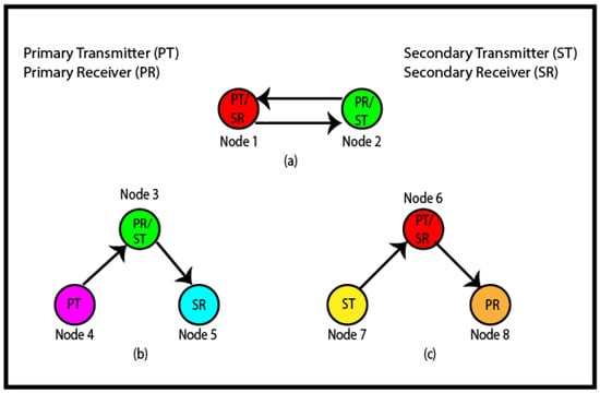
Figure 1.
Different types of IBFD transmission: (a) BFD, (b) destination-based TNFD, (c) source-based TNFD.
A MAC protocol named AdHoc-FDMAC for the ad hoc network using IBFD wireless communications has been proposed in this paper. The network structure of the proposed MAC is shown in Figure 2, where all the nodes are considered Full Duplex Nodes (FDNs) because of the advantages of FDNs over Half Duplex Nodes (HDNs). A conference paper has been published based on the basic idea of this proposed AdHoc-FDMAC [8]. Only BFD communications were considered in the paper [8]. However, in this paper, both source-based TNFD and destination-based TNFD communications along with BFD communications are considered. In addition, this paper shows different performance analyses, namely probability analysis, throughput analysis and routing time. The major contributions of this paper are given below:
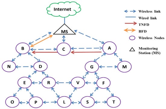
Figure 2.
Proposed network model for AdHoc-FDMAC. The single alphabets in the figure are node labels.
- An IBFD MAC protocol is proposed for the ad hoc network named AdHoc-FDMAC, where all nodes are FDNs.
- This MAC describes all possible types of IBFD communications.
- The performance analyses are performed in terms of probability analysis, throughput analysis and routing time.
- The throughput of this AdHoc-FDMAC is compared with a recently published ad hoc MAC protocol as well as with the conventional HD communications. The AdHoc-FDMAC significantly outperforms the existing ad hoc MAC that uses IBFD communications.
- The simulation result shows that the routing time is significantly lower than that of the conventional FD communications.
2. Literature Review
With the advancements in the physical layer, an effective MAC protocol is crucial in IBFD communications to exploit its benefit properly. A substantial amount of MAC protocols is proposed for ad hoc networks and other types of wireless networks. Although many of these protocols are designed using IBFD technique, all of them do not consider all possible types of IBFD communications as well as most of them are not proposed for ad hoc networks. Moreover, some of these do not consider the Inter-user-interference (IUI) and some cannot support the hidden and exposed terminal problems. A MAC protocol is designed in [2] for both infrastructure-based WLAN and ad hoc network, which supports all possible TNFD and BFD communications. However, this MAC cannot support the condition when transmitter and receiver nodes are out of the transmission range between each other in ad hoc networks. Moreover, the SR always measures the signal to interference ratio in that MAC during TNFD communications to extinguish IUI. Thus, it increases the computational load and network complexity. Furthermore, this design does not demonstrate the Network Allocation Vector (NAV) for various nodes. The authors in [9] proposed an OFDM-based 20 MHz multi-antenna FD MAC protocol. Another FD MAC has also been proposed in [10]. Both MAC protocols in [9,10] only consider BFD communications, but TNFD communications are not supported. Moreover, those MAC protocols are not for ad hoc networks. Another MAC protocol is proposed in [11] for the ad hoc networks using IBFD communications, where all the nodes are FDNs. This MAC is designed for BFD and destination-based TNFD communications, but it has not considered the source-based TNFD communications. Moreover, IUI is not considered in this MAC. Therefore, IUI will affect the TNFD communications greatly. In [12], a FD MAC protocol is proposed for ad hoc networks, which considers only BFD communications and destination-based TNFD communications, but source-based TNFD is not considered. Furthermore, in this MAC, to reduce IUI between PT to SR, ST uses its past information. This technique is not efficient for the networks where topological changes occur very rapidly.
A MAC protocol is proposed, named the distributed-access FD MAC in [13] for ad hoc networks, where the transmitting node transmits data to the receiver via intermediate nodes and all the nodes are FD capable. However, this paper does not describe how the path is selected from the transmitter to receiver. Recently, an IBFD MAC is proposed to perform Collision-Free FD (CFFD) communications among neighbours [14]. Here, the modified Request to Send (RTS) and Clear to Send (CTS) frames are used to reduce control message overhead, and these are used to reserve the data slot for FD transmission. However, the Acknowledgement (ACK) frame is not used here. Therefore, the source node is not informed whether data transmission is successful or not. It shows that no collision occurs in the data slot during data transmission. However, it is not clear how the data from a distant node will reach to the monitoring station or control center in an ad hoc network. In [15], an FD-MAC protocol is proposed for the infrastructure-based WLAN, where a shared random backoff, virtual backoff and header snooping methods are used for different types of IBFD of data transmission. This MAC supports BFD and source-based TNFD communications, but it does not consider destination-based TNFD communications. Furthermore, no handshake mechanism is used by this MAC; therefore, this MAC is not able to mitigate the hidden terminal problem. For asynchronous FD communications in ad hoc networks, a MAC is designed using the IBFD technique in [16]. That MAC only supports BFD communications; the TNFD is not supported by this MAC. In [17], an asymmetric MAC protocol is proposed for the infrastructure-based WLAN. In this design, all possible IBFD communications are considered except the source-based TNFD. This MAC considered IUI during TNFD communications.
A MAC protocol designed in [18] named Interference Free Full Duplex (IFFD) with power control MAC for WLAN, where only the AP is FDN and other nodes are HD capable. Thus, BFD communications are not possible by this MAC. Moreover, this MAC always analyses the transmission power of the transmitter and transmission range between the transmitter and receiver to mitigate IUI, which increases the complexity and computational load. The Full Duplex Multi-channel MAC (FD-MMAC) is proposed to mitigate the hidden terminal problem in the multi-channel for removing the controlling signals [19]. It considers the multi-channel exposed terminal problem. In this MAC protocol, the receiver node continuously transmits beacon packets during the whole period of data transmission. These beacon packets do not contain any kind of user information. Thus, this MAC cannot utilize FD potentiality completely based on user data communications. Moreover, due to the continuous beacon packet transmission by the receiver node during data transmission, this design is not enabled to perform the TNFD communications.
3. Proposed MAC Protocol: AdHoc-FDMAC
This MAC is proposed for FD communications using the IBFD technique, where all the nodes are FDNs. This section is described in two subsections, namely the control frame and data transmission.
3.1. Control Frame
In this proposed AdHoc-FDMAC protocol, we use a number of control frames, where some are the same as the frames that exist in the IEEE 802.11 standard, and these are RTS, CTS and ACK. However, some control frames are modified to support the IBFD communications. The modified control frames are CTS with Acknowledgement Indicator (CTS-AI), CTS with Secondary Receiver Address (CTS-SRA), which are depicted in Figure 3. A one-bit field named the Acknowledgement Indicator (AI) is appended with CTS frame to obtain CTS-AI, where the AI value ‘1’ means the PR has data to the PT as well as ‘0’ means the PR does not have data to the PT, and this new frame is used for the BFD and source-based TNFD communication. Similarly, to obtain CTS-SRA, a 6 bytes Secondary Receiver Address (SRA) field is comprised with the CTS frame, and it is utilized for destination-based TNFD communications. As the destination is out of the range of the transmitter, this paper applies the Ad hoc On-demand Distance Vector (AODV) routing algorithm to select the route in ad hoc networks. The Route Request (RREQ) and Route Reply (RREP) are the two frames of the AODV algorithm, which are also shown in Figure 3 [20].
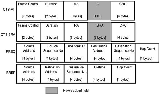
Figure 3.
Control frames.
3.2. Data Transmission
Data transmission in ad hoc networks is more complex than that in access point-based networks. In the access point-based network, all the nodes are connected through a common AP and a source node can easily transmit its message to the destination through AP. Conversely, if the destination node is out of the transmission range of the source in the ad hoc network, the source first selects an efficient route to the destination using a prominent routing algorithm and then transmits its data to the destination through this route using one or more relay nodes. The data transmission procedures using this AdHoc-FDMAC are described in the following two cases:
- Transmitter and receiver are out of the data transmission range;
- Transmitter and receiver are within the data transmission range.
3.2.1. Transmitter and Receiver Are out of the Data Transmission Range
If the destination or receiver is out of the transmission range of the source/transmitter, firstly it needs a route discovery protocol to find an efficient route from the source node to destination node. After selecting a route, the data transmission takes place from the source to the destination. In this paper, we use a famous route discovery protocol named AODV [20]. Here, at first the source sends a Route Request (RREQ) message to its neighbour nodes. The neighbours broadcast this message to their neighbours and this broadcast process is repeated continuously until the destination node is found. Every node has its own sequence number and broadcast ID. The RREQ message contains an important field, named the hop count, and this hop count is increased from every transmission of RREQ from one node to its neighbour node. An intermediate node can receive more than one RREQ messages with the same source address and broadcast ID from different neighbour nodes, but it only records the broadcast ID of the neighbour from which it first receives the RREQ message to its own route cache, and other RREQ messages received later are discarded. Every neighbour node maintains a route cache to set up a reverse path. When the RREQ message reaches the destination node, then the destination sends a Route Reply (RREP) message to the source through the same path that is used to send the RREQ message to destination. If the destination receives more than one RREQ message, it selects the route whose hop count is smaller. Before sending the RREQ/RREP, the transmitter senses the channel, whether it is idle or busy. If the channel is free, the transmitter sends the control frame.
The AODV protocol uses the conventional HD communications. However, we utilize AODV with IBFD communications, and it is depicted in Figure 4. According to the network topology, in Figure 2, node R and E have data to send C and MS respectively, but C is out of range of node R and MS is out of the range of E. In Figure 4, we demonstrate how both R and E nodes select the route to transmit thee data to their destination simultaneously.
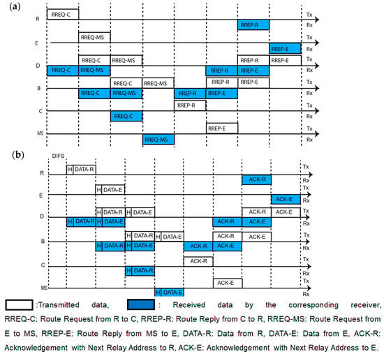
Figure 4.
FD data transmission when transmitter and receiver nodes are out of the range between each other; (a) route selection process; (b) data transmission process.
To select a route, E transmits the RREQ message to D, D to B and B transmits the RREQ to both MS and C simultaneously and then C sends it to MS. Although the destination MS receives two RREQ massages from E using two different routes, MS selects the E-D-B-MS route according to the AODV algorithm, as the hop count is smaller here. Similarly, another node R selects the R-D-B-C route using the AODV algorithm at the same time.
We divide the total data transmission process into two parts, namely the Figure 4a route selection process and Figure 4b data transmission process. According to Figure 4a, R transmits a RREQ-C message to the relay node D and it receives this message. Then, D transmits RREQ-C to B. While transmitting RREQ-C, D also receives RREQ-MS that is transmitted by E, as shown in Figure 4a. After that, D sends RREQ-MS to B and at the same time, B sends RREQ-C to destination node C. After receiving RREQ-C from B, C waits for processing the information and B sends RREQ-MS to destination MS. Then, C sends a route reply RREP-R to B. Afterwards, MS transmits RREP-E (route reply to the source E) frame to B. By using these relay nodes B and D, both C and MS transmit their RREP-R and RREP-E frame to the sources R and E, respectively. Consequently, according to the previous description, the route reply reaches to its destination. After receiving the route reply, the data transmission process takes the place as shown in Figure 4b. Afterwards, both data frames are relayed by relay nodes D and B and are received by C and MS, as in Figure 4b. After data transmission, both C and MS send their acknowledgement frames to the corresponding transmitters.
3.2.2. Transmitter and Receiver Are within the Data Transmission Range
Here, IBFD data transmissions are described in the following two sub-sections, when transmitter and receiver are in the data transmission range, namely:
- BFD communications;
- TNFD communications.
BFD Communications
In the ad hoc network, Downlink (DL) data flow (From MS to any node) is not so high compared to Uplink (UL) data flow (from any node to MS). Hence, the volume of data flow from MS to other nodes is lower than that of other nodes to MS. For this reason, there is a higher probability that when MS initiates the transmission, the corresponding receiver node also has data for MS. Therefore, the probability is very high to be BFD communications when MS initiates transmissions. The data transmission process for BFD communications with our proposed MAC is shown in Figure 5. According to Figure 5, both MS and B have data for each other. At first, MS senses whether the channel is idle or not. If the channel is idle and back-off timer reaches zero, it transmits an RTS to B and waits for a SIFS time. After receiving RTS, B transmits a CTS-AI frame to MS with the AI value ‘1′ and all the neighbour nodes are informed that B is ready to receive from MS and also has data for MS. Then the BFD communication is performed, as shown in the Figure 5. After finishing data transmission, both nodes exchange their ACK frames. However, HD communication takes place, if B as well as other nodes, which are hidden to the MS, have no data to send.
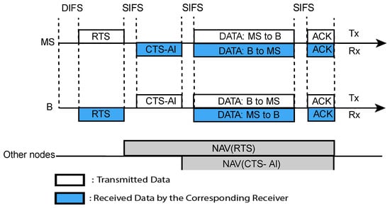
Figure 5.
Time sequence of the proposed MAC for BFD (the MS initiates the transmission).
TNFD Communications
When a PT transmits data to a PR, any ST may provide data to the PT or the PR may provide data to any SR. First one is the source-based TNFD and second one is the destination-based TNFD communications, which is discussed in the introduction section. The TNFD communications in AdHoc-FDMAC are described below with proper time sequence diagrams.
Source-Based TNFD Communications
The time sequence for source-based TNFD communication is shown in Figure 6. Here, we have described this communication using five nodes, namely A, C, F, G and M, where node A is considered as PT and SR, node G is PR and node M is ST. When PT wins the channel access, it sends its data to PR. We assume that the node A has data to node G and A obtains the channel access. At first, A transmits its RTS to G. After receiving RTS, the node G waits for a SIFS time and then transmits CTS-AI to A, where the AI value is ‘0′, which means node G has no data for A. After that, the node A broadcasts a ‘1′ bit flag named the Notification Flag (NF) to inform its neighbours that the nodes who want to transmit data to A can transmit now. Hence, the nodes that have data for the PT and hear the NF but cannot hear the CTS-AI, stop their NAV and start their Random Timer (RT). This condition is applied to mitigate the inter-user interference. The node whose RT value is minimum, sends its data packet to the PT after sensing the channel idle. As shown in Figure 6, nodes C, M and F start their RTs and M’s random timer value is minimum. Therefore, M sends data to A. When the RTs of other nodes (C and F) stop, the nodes sense the channel and find it busy, as M already started its transmission.
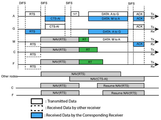
Figure 6.
Time sequence of the proposed MAC for source-based TNFD (the rest of the nodes except MS initiate the transmission).
Therefore, node C and F resume their NAVs. Node A also transmits it data packet to G simultaneously. At the end of data transmission, both receiver nodes reply with ACK to their corresponding transmitters. If the ST does not provide data to PT A, the HD communication will take place.
Destination-Based TNFD Communications
The time sequence for the destination-based TNFD communications is shown in Figure 7. As shown in the Figure 7, the PT (node A) starts the transmission by sending RTS to the PR (node C). In this case, the PR has no data to the PT, but it has data for another node B that is the SR now. Thus, after receiving the RTS, the PR waits a SIFS time and transmits a CTS-SRA frame to both the PT and SR. This CTS-SRA frame contains the address of the SR in its SRA field. Therefore, both PT and SR are informed that C has data to B. After hearing CTS-SRA, node B sends CTS, if it cannot hear RTS from A (this condition is to mitigate the inter-user interference). Afterwards, nodes A and C transmit their data to the corresponding receiver nodes C and B, respectively. After receiving the data packets, both PR (node C) and SR (node B) sends the ACK frame to their corresponding transmitters. If the SR does not reply with CTS-SRA, it becomes an HD communication only.
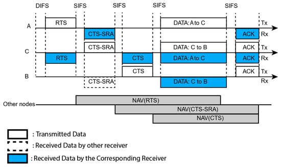
Figure 7.
Time sequence of the proposed MAC for destination-based TNFD (the rest of the nodes except MS initiate the transmission).
4. Mathematical Analysis
In this section, we calculate the probability equations for BFD and TNFD communications, because most of communications will be either BFD communications or TNFD communications, if it is considered that all nodes have data to send. The probability equations are calculated using the Packet Generation Rate (PGR) by each node (λ). We assume that the total number of nodes are ‘n’ and the percentage of hidden nodes is ‘α’. Here, it is considered that packet arrival process is the ‘Poisson process’ and the service time distribution is ‘exponential’.
In general, packets wait in the queue before transmission. The average waiting time before transmission is and it is assumed as an M/M/1 queueing system. Therefore, the equation of the average waiting time is,
where, is the total PGR and is the average service rate of the MS.
The symbols and description of different variables that we use to calculate probability equations are listed in Table 1.

Table 1.
Declaration of variables.
4.1. Probability Analysis
The probability equations of BFD and TNFD communications are derived here, and it is described in this section.
4.1.1. Probability Equation for BFD Communications
When a PT initiates the transmission by sending RTS to a PR, BFD will take place if the PR has data for the PT; the probabilities are given below:
- The conditional probability that the PT (or MS) has a data packet for PR is .
- The probability that the corresponding PR has at least one data packet for PT in time is .
Therefore, the probability for BFD communication is,
4.1.2. Probability Equation for TNFD Communications
The probability equations for the two types of TNFD communications are derived in this section, and these are described as follows,
Source-Based TNFD Communications
- The conditional probability that PT has data packet for PR is .
- The probability that the corresponding PR does not have data for corresponding PT in time is .
- The nodes (ST) that are hidden to the PR have minimum one data packet for the PT in time (where, ) is .
Hence, the probability for the STNFD communications is,
Destination Based TNFD Communications
- The conditional probability that the PT has data for PR is .
- The probability that the corresponding PR does not have data for the PT in time is .
- The probability that the PR (it acts as ST also) has minimum one data packet in time for any other node that is hidden from PT and is in the range of PR is .
Thus, the probability for the DTNFD communication is,
Therefore, the total probability for TNFD communication is,
4.2. Throughput Calculation
In this MAC protocol, we consider the data traffic is symmetric. Thus, the uplink data length and downlink data length () are the same size during the data transmission. Let, . To calculate the throughput, we use the following formula:
Presently, the throughput is calculated for BFD, TNFD and HD communications, using the following equations,
where,
5. Result and Performance Analysis
The performance analysis is described in three subsections, namely, the probability analysis, throughput analysis and routing time. All the simulations are performed in MATLAB. The simulation parameters are shown in Table 2.

Table 2.
Declaration of variables.
5.1. Probability Analysis
The probability of BFD and TNFD communications with respect to PGR is shown in Figure 8, and the probability of BFD and TNFD communications with respect to the total number of nodes is shown in Figure 9.
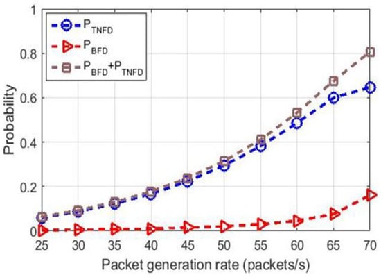
Figure 8.
Probability for TNFD and FD communications vs. PGR.
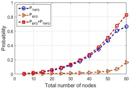
Figure 9.
Probability for TNFD communications vs. total number of nodes.
Figure 8 shows the probability analysis for TNFD communications with respect to PGR by each node (packets/s). In this simulation, the number of nodes is 50. The PGR by each node is varied from 25 packets/s to 70 packets/s. According to the figure, the probability for TNFD communications increases significantly with the increase in PGR. However, the probability for BFD communications grows slowly with the increase in PGR. Therefore, the overall probability for FD communications has an increasing trend.
The results of the probability analysis of different type FD communications with respect to the total number of nodes are depicted in Figure 9, where total number of nodes is varied from 5 to 60 nodes. Here, the PGRs are considered as 70 packets/s. According to Figure 9, the probability for TNFD communications is growing significantly, as the total number of nodes increases. This is because, if the total number of nodes increases, the possibility of having more nodes to send data after initiating a transmission by a PT also increases.
On the other hand, the probability for BFD communications is increasing slowly, as the number of nodes increases, because most of the cases of BFD communications takes place when MS initiates the transmission, which is discussed earlier in Section 3.2.2. Therefore, the increase in the number of nodes does not have a high impact on BFD communications, but has a great impact on TNFD communications.
5.2. Throughput Analysis
The throughput analysis of the proposed AdHoc-FDMAC is performed in a saturation condition where all the nodes have data to transmit. The simulation for the throughput analysis is conducted by MATLAB and the result is shown in Figure 10, where the throughput of the proposed AdHoc-FD MAC is compared with the conventional HD as well as with a recently published MAC protocol named CFFD-MAC [14]. The simulation parameters are shown in Table 2.
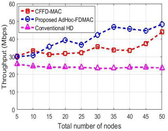
Figure 10.
Throughput comparison.
As shown in the Figure 10, the average throughput for the conventional HD communication is 24.06 Mbps. The average throughput for AdHoc-FDMAC is 40.06 Mbps, which has a 66.50% increase compared with the conventional HD.
In this simulation, 20% of the nodes are considered as hidden nodes. According to Figure 10, the throughput increases as the number of nodes increases. As the number of nodes increases, the number of hidden nodes also increases and thus the occurrences of having TNFD communications increase. Therefore, the overall throughput increases.
The throughput of AdHoc-FDMAC and CFFD-MAC are almost same when the number of nodes are 5 to 10 (Figure 10). After that, the throughput for CFFD-MAC decreases gradually compared to the AdHoc-FDMAC, with the increase in the number nodes. This is because, if the number of nodes increases, more TNFD communications take place and the control overhead for TNFD in CFFD-MAC is higher than that for TNFD in AdHoc-FDMAC. Thus, the throughput of CFFD-MAC becomes lower than that of the AdHoc-FDMAC, when the number of nodes increases. The average throughput of AdHoc-FDMAC and CFFD-MAC are 40.06 Mbps and 34.30 Mbps, respectively. Therefore, AdHoc-FDMAC outperforms CFFD-MAC by 16.80% average throughput gain.
5.3. Routing Time
In this AdHoc-FDMAC, the AODV routing algorithm is used to select an efficient route. The AODV algorithm is used in the AdHoc-FDMAC using the IBFD communications. The comparison of the routing time of the AODV algorithm using the IBFD technique (described in Section 3.2.1) and routing time of the conventional AODV algorithm (without using IBFD technique) is shown in Figure 11. To calculate the routing time, we consider a node in the network from which three hops are required for a packet to reach the MS (final destination). Hence, if the packet requires more hops, the routing time becomes higher. The figure shows that routing time of AODV algorithm in AdHoc-FDMAC is 33.33% less than the conventional AODV routing.
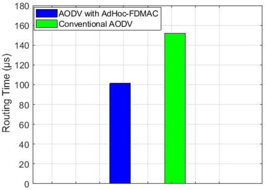
Figure 11.
Routing time comparison.
6. Conclusions
This paper proposes a MAC protocol for the ad hoc network using IBFD communications, which is a state-of-the-art MAC for wireless communications named AdHoc-FDMAC. The proposed MAC has been found to have the capability to improve the throughput significantly compared to a recent publication in this area. The proposed AdHoc-FDMAC also outperforms the conventional counterpart in terms of throughput and routing time. As we have to handle a huge volume of traffic, we need to incorporate IBFD communications in all kinds of wireless networks. Therefore, this AdHoc-FDMAC will play a vital role in the future ad hoc networks. In this paper, we have considered the symmetric data traffic and AODV routing algorithm. In the future, this research can be extended for the asymmetric data traffic. In addition, other proactive and reactive routing algorithms can be incorporated in the future research on the MAC protocol design for ad hoc networks.
This ADHoc-FDMAC protocol is not fully compatible with the present IEEE standard. IBFD is a new technology and the existing IEEE standard does not support the IBFD communications. Therefore, the existing wireless communication devices (such as laptops, mobile phones, WiFi routers, etc.) are not able to perform this IBFD communication as well, as this MAC protocol cannot be implemented in these existing devices. To support the huge data in our limited bandwidth, IBFD is one of the best potential technologies to be implemented in the upcoming new devices. On the other hand, this AdHoc-FDMAC is applicable to all the applications that are provided by the existing AdHoc networks, but this proposed MAC has a higher capability to handle more data than the existing one.
Author Contributions
Conceptualization, network model and protocol design, M.A.R. and M.A.A.; methodology, M.A.R., M.M.R. and M.A.A.; mathematical analysis, M.A.R. and M.A.A.; simulation, M.A.R.; writing and editing of the manuscript, M.A.R., M.M.R. and M.A.A.; supervision and funding, M.A.A. All authors have read and agreed to the published version of the manuscript.
Funding
This research is funded by the Khulna University Research Cell (KURC Project FY 2020-21).
Data Availability Statement
Data are available from the authors, on request.
Conflicts of Interest
The authors declare no conflict of interest.
Abbreviations
The following abbreviations are used in this manuscript:
| ACK | Acknowledgement |
| ACK-E | Acknowledgement with Next Relay Address to E |
| ACK-R | Acknowledgement with Next Relay Address to R |
| ALMS | Analog Least Mean Square |
| AODV | Ad hoc On-demand Distance Vector |
| AP | Access Point |
| BFD | Bidirectional Full Duplex |
| BS | Base Station |
| CFFD | Collision-free FD |
| CTS | Clear to Send |
| CTS-AI | CTS with Acknowledgement Indicator |
| CTS-SRA | CTS with Secondary Receiver Address |
| DATA-E | Data from E |
| DATA-R | Data from R |
| DCF | Distributed Coordination Function |
| DIFS | Distributed Inter-frame Space |
| DL | Downlink |
| DTNFD | Destination-Based TNFD |
| FD | Full Duplex |
| FD-MMAC | Full Duplex Multi-channel MAC |
| FDNs | Full Duplex Nodes |
| HD | Half Duplex |
| HDNs | Half Duplex Nodes |
| IBFD | In-band Full-duplex |
| IFFD | Interference Free Full Duplex |
| IUI | Inter-user–interference |
| MAC | Medium Access Control |
| MS | Monitoring Station |
| NAV | Network Allocation Vector |
| NAV(CTS) | NAV for CTS |
| NAV(CTS-AI) | NAV for CTS-AI |
| NAV(CTS-SRA) | NAV for CTS-SRA |
| NAV(RTS) | NAV for RTS |
| OFDM | Orthogonal Frequency-division Multiplexing |
| PGR | Packet Generation Rate |
| PR | Primary Receiver |
| PT | Primary Transmitter |
| RREP | Route Reply |
| RREP-E | Route Reply from MS to E |
| RREP-R | Route Reply from C to R |
| RREQ | Route Request |
| RREQ-C | Route Request from R to C |
| RREQ-MS | Route Request from E to MS |
| RTS | Request to Send |
| SIFS | Short Inter-frame Space |
| SR | Secondary Receiver |
| ST | Secondary Transmitter |
| STNFD | Source-Based TNFD |
| TNFD | Three Node Full Duplex |
| UL | Uplink |
| WLAN | Wireless Local Area Network |
References
- Helen, D.; Arivazhagan, D. Applications, advantages and challenges of ad hoc networks. J. Acad. Ind. Res. (JAIR) 2014, 2, 453–457. [Google Scholar]
- Goyal, S.; Liu, P.; Gurbuz, O.; Erkip, E.; Panwar, S. A distributed MAC protocol for full duplex radio. In 2013 Asilomar Conference on Signals, Systems and Computers; IEEE: Piscataway, NJ, USA, 2013. [Google Scholar]
- Le, A.T.; Tran, L.C.; Huang, X.; Guo, Y.J. Analog least mean square loop for self-interference cancellation: A practical perspective. Sensors 2020, 20, 270. [Google Scholar] [CrossRef] [PubMed]
- Radunovic, B.; Gunawardena, D.; Key, P.; Proutiere, A.; Singh, N.; Balan, V.; Dejean, G. Rethinking indoor wireless mesh design: Low power, low frequency, full-duplex. In 2010 Fifth IEEE Workshop on Wireless Mesh Networks; IEEE: Piscataway, NJ, USA, 2010. [Google Scholar]
- Bharadia, D.; McMilin, E.; Katti, S. Full Duplex Radios. In Proceedings of the ACM SIGCOMM, Hong Kong, China, 12–16 August 2013; Volume 10, p. 375386. [Google Scholar]
- Kim, D.; Lee, H.; Hong, D. A survey of in-band full-duplex transmission: From the perspective of PHY and MAC layers. IEEE Commun. Surv. Tutor. 2015, 17, 2017–2046. [Google Scholar] [CrossRef]
- Thilina, K.M.; Tabassum, H.; Hossain, E.; Kim, D.I. Medium access control design for full duplex wireless systems: Challenges and approaches. IEEE Commun. Mag. 2015, 53, 112–120. [Google Scholar] [CrossRef]
- Rahman, M.A.; Rahman, M.; Alim, M. In-band Full-duplex MAC Protocol for Ad Hoc Networks. In 2021 International Conference on Electronics, Communications and Information Technology (ICECIT); IEEE: Piscataway, NJ, USA, 2021. [Google Scholar]
- Duarte, M.; Sabharwal, A.; Aggarwal, V.; Jana, R.; Ramakrishnan, K.K.; Rice, C.W.; Shankaranarayanan, N.K. Design and characterization of a full-duplex multiantenna system for WiFi networks. IEEE Trans. Veh. Technol. 2013, 63, 1160–1177. [Google Scholar] [CrossRef]
- Jain, M.; Choi, J.I.; Kim, T.; Bharadia, D.; Seth, S.; Srinivasan, K.; Levis, P.; Katti, S.; Sinha, P. Practical, real-time, full duplex wireless. In Proceedings of the 17th Annual International Conference on Mobile Computing and Networking, Las Vegas, NV, USA, 19–23 September 2011. [Google Scholar]
- Cheng, W.; Zhang, X.; Zhang, H. RTS/FCTS mechanism based full-duplex MAC protocol for wireless networks. In 2013 IEEE Global Communications Conference (GLOBECOM); IEEE: Piscataway, NJ, USA, 2013. [Google Scholar]
- Singh, N.; Gunawardena, D.; Proutiere, A.; Radunovi, B.; Balan, H.V.; Key, P. Efficient and fair MAC for wireless networks with self-interference cancellation. In 2011 International Symposium of Modeling and Optimization of Mobile, Ad Hoc, and Wireless Networks; IEEE: Piscataway, NJ, USA, 2011. [Google Scholar]
- Askari, E.; Aïssa, S. Single-band full-duplex MAC protocol for distributed access networks. IET Commun. 2014, 8, 1663–1673. [Google Scholar] [CrossRef]
- Rukaiya, R.; Farooq, M.U.; Khan, S.A.; Hussain, F.; Akhunzada, A. CFFD-MAC: A hybrid MAC for collision free full-duplex communication in wireless ad-hoc networks. IEEE Access 2021, 9, 35584–35598. [Google Scholar] [CrossRef]
- Sahai, A.; Patel, G.; Sabharwal, A. Pushing the limits of full-duplex: Design and real-time implementation. arXiv Preprint 2011, arXiv:1107.0607. [Google Scholar]
- Tang, D.; Zhang, C.; Song, R. Asynchronous In-band Full-Duplex Transmission Scheme for Ad-Hoc Networks. In Proceedings of the 2020 4th International Conference on Electronic Information Technology and Computer Engineering, Xiamen, China, 6–8 November 2020. [Google Scholar]
- Chen, C.; Hou, S.; Wu, S. Saturation throughput analysis of an asymmetric full-duplex MAC protocol in WLANs with hidden terminals. IEEE Access 2018, 6, 69948–69960. [Google Scholar] [CrossRef]
- Chen, Y.-D.; Chen, I.-J.; Shih, K.-P. An in-band full duplex MAC protocol with interference free for next generation WLANs. In 2018 International Conference on Electronics Technology (ICET); IEEE: Piscataway, NJ, USA, 2018. [Google Scholar]
- Zhang, Y.; Lazos, L.; Chen, K.; Hu, B.; Shivaramaiah, S. FD-MMAC: Combating multi-channel hidden and exposed terminals using a single transceiver. In IEEE INFOCOM 2014-IEEE Conference on Computer Communications; IEEE: Piscataway, NJ, USA, 2014. [Google Scholar]
- Maurya, P.K.; Sharma, G.; Sahu, V.; Roberts, A.; Srivastava, M.; Scholar, M.T. An overview of AODV routing protocol. Int. J. Mod. Eng. Res. (IJMER) 2012, 2, 728–732. [Google Scholar]
Disclaimer/Publisher’s Note: The statements, opinions and data contained in all publications are solely those of the individual author(s) and contributor(s) and not of MDPI and/or the editor(s). MDPI and/or the editor(s) disclaim responsibility for any injury to people or property resulting from any ideas, methods, instructions or products referred to in the content. |
© 2023 by the authors. Licensee MDPI, Basel, Switzerland. This article is an open access article distributed under the terms and conditions of the Creative Commons Attribution (CC BY) license (https://creativecommons.org/licenses/by/4.0/).