Article

Multi-Tier Cellular Handover with Multi-Access Edge Computing and Deep Learning

Department of Electrical and Electronic Engineering, Auckland University of Technology, Auckland 1010, New Zealand
*
Author to whom correspondence should be addressed.
Telecom 2021, 2(4), 446-471; https://doi.org/10.3390/telecom2040026
Submission received: 7 October 2021 / Revised: 29 October 2021 / Accepted: 11 November 2021 / Published: 15 November 2021
(This article belongs to the Special Issue Machine Learning and Cognitive Networking)

Abstract

:
This paper proposes a potential enhancement of handover for the next-generation multi-tier cellular network, utilizing two fifth-generation (5G) enabling technologies: multi-access edge computing (MEC) and machine learning (ML). MEC and ML techniques are the primary enablers for enhanced mobile broadband (eMBB) and ultra-reliable and low latency communication (URLLC). The subset of ML chosen for this research is deep learning (DL), as it is adept at learning long-term dependencies. A variant of artificial neural networks called a long short-term memory (LSTM) network is used in conjunction with a look-up table (LUT) as part of the proposed solution. Subsequently, edge computing virtualization methods are utilized to reduce handover latency and increase the overall throughput of the network. A realistic simulation of the proposed solution in a multi-tier 5G radio access network (RAN) showed a 40–60% improvement in overall throughput. Although the proposed scheme may increase the number of handovers, it is effective in reducing the handover failure (HOF) and ping-pong rates by 30% and 86%, respectively, compared to the current 3GPP scheme.

1. Introduction

With the introduction of the fifth-generation (5G) cellular network [1], the industry is posed with many diverse challenges. A common challenge to all three major pillars of 5G (enhanced mobile broadband (eMBB), massive machine-type communications (mMTC), and ultra-reliable low latency communications (URLLC)) is seamless and low latency multi-tier handover. In the latest 3rd generation partnership project (3GPP) standards for 5G [2], it was noticed that the event-based triggering for handover ignores various key elements of the user’s session that require to be taken into consideration, such as their mobilities and data rate requirements. The user requirements are ever-changing; thus, cellular networks must be sufficiently dynamic to react and cater to this demand effectively. There are various channel inefficiencies that occur when a diverse range of requirements are not taken into consideration.
The issues relating to multi-tier handovers have not been effectively resolved to this day. There is literature addressing the issues of handover, but only a small portion of these adopt a form of artificial intelligence (AI) or cloud computing techniques in their solutions. The use of deep learning (DL) and multi-access edge computing (MEC) for optimizing handover is still a gap in the industry that has not been explored yet.
With the addition of MEC and DL in 5G, network operators can gather user data and analyze variations in signal strength, mobility patterns, and data rate requirements of each user to achieve optimum user experience. Additionally, with the implementation of a system that understands the user’s requirements, network elements also benefit because this helps to manage the base station’s resources efficiently. Keep in mind that the network operators should extract or use all of these data without compromising on the compliance of user privacy laws of the specific country.
The objective of this paper is to develop a DL handover decision algorithm while utilizing MEC. This will enable a faster and more reliable handover system that would ideally allow the user to switch seamlessly between any cellular network configurations based on key requirements. The scope of this research is focused on a 5G heterogeneous environment with various base station tiers (macro, micro, and femtocells) to carry out a comprehensive multi-tier handover evaluation. This research is validated by conducting software simulations to compare the proposed method to the handover technique specified by 3GPP in the technical standard (TS) 38.300 [3]. Both key components of the simulator: channel model and scheduler, are compliant with 3GPP standards 38.104 [4] and 36.873 [5], respectively. The main contributions of this paper are as follow:
  • Proposal of a new DL Long Short-Term Memory (LSTM) handover decision algorithm that uses a look-up table (LUT) and is catered to key user quality of experience (QoE) and quality of service (QoS) requirements;
  • Replacement of the time to trigger (TTT) with a dynamic LUT-based trigger mechanism;
  • Modification of the handover admission control process when using the DL LSTM logic to occur at the same time instant that the base station sends the handover command to the UE. This is assuming that the user plane function (UPF) and the access and mobility management function (AMF) is located at the MEC aggregated edge.
The rest of this paper is organized as follows: Section 2 provides some necessary preliminaries. Section 3 overviews the related works. Section 4 introduces the system model. Section 5 presents the proposed algorithm. The simulation model and performance metrics are described in Section 6. This is followed by results and discussion in Section 7. Finally, Section 8 concludes the paper with some directions for future work.

2. Preliminaries

2.1. Multi-Tier Intra-RAT Handover

This paper focuses on enhancing the 5G multi-tier intra-radio access technology (RAT) handover. This refers to a handover where the current and target BSs involved in the handover of user equipment (UE) are located in different tiers of the network, and the RAT of both current and target BSs is the same [6]. In 5G networks, a BS that connects the UE to the 5G core (5GC) via next-generation (NG) interfaces is referred to as a gNodeB (gNB) [3]. The intra-RAT handovers occur in the AMF and UPF elements of the 5G architecture.
This paper models the handover functions performed by the UE, gNB, AMF, and UPF as specified in the non-roaming architecture for 5G in 3GPP standard TS 23.501 [7]. The AMF manages the handovers between different gNBs, while UPF supports service features such as packet routing for the UE. Both AMF and UPF communicate with the gNBs through the N2 and N3 interface, respectively.

2.1.1. 3GPP Defined Logic and Procedure

This section overviews the handover logic and procedure defined in 3GPP TSs 38.331 [8] and 38.300 [3], respectively. Before detailing these steps, an understanding of how a UE switches between idle and connected states are described below:
  • Idle: A UE is in the idle state when its context is known to the 5GC but does not have an established connection to a gNB. In this state, the UE listens and responds to broadcasted messages from gNBs. It performs measurements and cell reselection methods when it is ready to connect to a gNB;
  • Connected: A UE is in the connected state when its context is known to both 5GC and gNB. In this state, the UE provides periodic measurement reports with channel quality information (CQI). Data are regularly transferred in this phase.
At set timestamps during the connected state, the UE sends measurement reports for the AMF to assess whether a handover is necessary. Usually, it is based on the UE’s received signal strength (RSS) for its associated BS, although sometimes other factors such as loading are considered. The way the AMF decides whether a handover is to occur is decided based on an event-triggered system. Events are triggered by the logic described in [8]. There are various event triggers, and their parameters are specified in Table 1 and Table 2. Events A1 through A6 are only considered as they relate to intra-RAT handover; other events such as B1 are not relevant to this work as they relate to inter-RAT handover.
Each event has an entry and leaving condition. If the entry condition is satisfied for longer than a certain period, called the time to trigger (TTT), the BS will initiate the handover procedure to the desired cell. However, if the UE’s reference signal received power (RSRP) drops below the leaving condition or does not meet the entry condition after the TTT, the UE remains connected to the current BS, as the desired BS no longer meets the criteria.
This paper focuses on implementing two of the handover events, A1 and A3. Other events are not considered as there will be unnecessary complexities introduced that will diverge from the scope of this work. For example, an A6 handover would require a form of dual connectivity for the user to perform and assess this event correctly. After the UE has met the entry condition for the duration of the TTT interval, a handover procedure is initiated. There are three phases [3]:
  • Preparation: Upon deciding to handover, the source gNB sends a handover request to target gNB, which in turn processes the request and completes the admission control by returning a handover request acknowledgment to the source gNB;
  • Execution: Upon being notified by source gNB, UE begins to detach from source gNB and synchronizes to target gNB. Simultaneously, source gNB executes a sequence number (SN) status transfer and delivers buffered and new data from UPF to target gNB;
  • Completion: This phase begins with a path switch requested by the target gNB, which triggers the 5GC to switch the path of the UE’s data to the target gNB via the UPF. Then UPF sends the end marker for source gNB via the AMF, which in turn sends a path switch acknowledgment. Finally, the target gNB sends a message to source gNB to release the context of the UE, completing the handover procedure.

2.2. Far and Aggregated MEC

While the traditional cloud computing services reside in the core, multi-access edge computing (MEC) enables decentralized cloud-like services close to the edge of a network, allowing for lower latencies and higher throughputs for users [9]. Figure 1 highlights their key differences. This paper focuses on the two edge data center architectures, (i) far edge and (ii) aggregated edge, to achieve a handover latency that approaches the user plane eMBB and URLLC latency targets of less than 4 ms and 1 ms, respectively [10].

2.3. LSTM

This paper focuses on one of the popular deep learning algorithms called long short-term memory (LSTM), which is known to be able to learn and memorize long-term dependencies [11]. LSTMs consist of one cell state and various gates. The cell state is the “memory” part of the LSTM, which can be altered by various gates, each comprising of a sigmoid neural network layer and a pointwise multiplication operation [12]. While different variants of LSTMs exist, such as peephole connections [13] and gated recurrent unit (GRU) [14], this paper uses the standard LSTM as it is ideal for classifications of sequence data. A detailed explanation of the LSTM process can be found in [11].

3. Related Works

This section classifies and analyzes the literature on multi-tier handovers under three solution approaches: multi-connectivity, AI, and cloud/edge-based approaches, and highlights key areas for improvement.

3.1. Multi-Connectivity Approach

Multi-connectivity refers to the situation when a user is connected to more than one BS to ensure that its connection to the network is not lost. Soft handovers, considered in this paper, are a type of multi-connectivity, as when handing over, the user is connected to multiple BSs at once for a small amount of time. In the following, we review the literature that employs multi-connectivity for multi-tier handovers.
In [15], the issue of high handover latency and signaling overhead was addressed. The authors proposed that the UE is always connected to two 5G millimeter-wave access points (mmAPs) and one LTE BS. The proposed scheme compares the predicted RSS of the active set of 5G-mmAPs and one LTE-BS to another candidate, LTE-BS or 5G-mmAP. If the candidate device has a better RSS, the network will initiate a handover request to the core network. The proposed algorithm is compared to two systems: A3 event-based logic and the current scheme but without prediction. Simulation results show that the average throughput of the proposed scheme is improved by 12% under moderately high mobility (30–50 km/h). Additionally, the number of handovers is also reduced by 5%. However, it is observed that although the system is a multi-tier network, it lacks a detailed study on multi-tier handover as the focus is primarily on the 5G-mmAPs. It is also observed that the resulting channel efficiency is reduced since the UE uses three forms of connectivity to achieve minor improvements. This issue can pose a major constraint when this is deployed in a populated environment.
The same channel efficiency and signaling overhead issues are accentuated in [16], where the authors aim to address the issue of mm-waves being highly susceptible to blockages and degradation in channel quality. The proposed solution consists of a heterogeneous dual-connectivity solution that connects UEs to both 4G LTE and 5G mm-wave BSs, providing rapid switching from 5G to 4G for failures on any link. Additionally, the solution added the complexity of including static and dynamic TTT delays. The proposed algorithm is compared with that of 3GPP for vertical handover. In terms of the number of handovers executed, the 3GPP algorithm is more efficient by 5–10%, as the proposed dual-connectivity approach requires the handovers to occur more frequently as user requirements change. However, the handover latency is reduced by 70%, while the overall throughput is marginally improved by 2–5%.
In [17], the authors proposed a combination of soft and hard handover solutions for horizontal and vertical handover in a vehicular network. The proposed algorithm uses circular geometric calculations to model the cell’s coverage, relying on the vehicle’s GPS coordinates to trace the path accurately. It also uses soft handover between roadside units (RSUs) and hard handover between RSU and BS. Additionally, the handover latency is considered when the algorithm executes its decision, resulting in a combination of the cell with the lowest latency and the best QoS. The proposed solution is compared with the 3GPP threshold and signal hysteresis methods to determine if the number of handovers and HOFs are reduced. The algorithm provided a reduction of 30% in handovers and a 25% reduction in HOFs at speeds of 100 km/h. However, there are two potential drawbacks to this proposed solution: (i) The signal overhead for RSU and BS will increase dramatically as the density of vehicles grows. Hence, the equipment cost on the network side to support this will increase. (ii) The system present in the vehicle requires at least three other separate systems to be able to execute handovers, which would further add to the cost of the system.

3.2. AI Approach

AI-based handover is where the system learns user patterns and dependencies and attempts to find the most optimal solution through its learning. AI can include forms of ML as well as other forms of evolutionary learning. This section divulges details of the improvements that AI-based schemes can provide for multi-tier handovers.
The authors of [18] proposed to use fuzzy logic to solve issues relating to redundant handovers and HOF ratios in dense small cell networks in LTE. A self-optimizing system that analyses the user velocity and radio channel quality and adapts hysteresis values for handover decisions is proposed. The inputs for the system are the user velocity, RSRP, and reference signal received quality (RSRQ). The proposed algorithm is compared to four other algorithms: Best Connection, Conventional LTE handover, Fuzzy Multiple-Criteria Cell Selection integrated with TOPSIS, and Self-Tuning Handover Algorithm. The proposed algorithm reduced the average number of handovers by 20%, the overall HOF ratio by 25%, and the ping-pongs events by 50%. However, the impact on latency and throughput has not been analyzed, which could insinuate a possible increase in computational strains, resulting in a reduction in the user’s quality of experience.
In [19], the authors addressed the inefficiencies of handover for in-building systems. The proposal is to optimize these inefficiencies through ML and data mining techniques by developing a clustering algorithm based on shapelets and wavelet decompositions at the cell’s edge. The considered environment consists of two in-building systems on a university campus and a three-sector macro-cell. The authors developed objective functions for three scenarios of loading the macro-cell and in-building systems (assuming UEs are exiting the building) to achieve the optimal operating point, which is a combination of the A2 and A3 handover thresholds and a TTT period. The optimal operating points were based on HOF, ping-pong, and average data rates. The achieved data rate gain by this algorithm is between 25% and 65% over the static A3 algorithm. The authors discussed ping-pong and HOF rates but did not provide evidence of improvements in these areas. It is also unclear how the proposed algorithm would perform when there are mass user movements, such as leaving the building when a class finishes.
A DL approach was analyzed in [20], where the authors proposed to significantly reduce service traffic that is transmitted through the 5G communication channels and to optimize handovers. The proposed algorithm uses gated recurrent units (GRUs) to provide a rapid response to changes in the environment. The GRU is used to predict how many users would be in a particular cell for a given the time of day. The prediction scheme varies the size of the cell coverages based on the time of day. This allows underloaded cells to be easily handed over and overloaded cells to become harder to connect into. The authors used supervised learning for these predictions and compared them to a DL LSTM over 300 epochs. It is shown that the GRU can achieve a better result than the LSTM in a short time frame, although the LSTM becomes more accurate as the number of epochs increases. It is also shown that the GRU can accurately model daily user traffic with an accuracy of 90%. However, the authors did not state when all cells are overloaded, which would cause the coverages to become so small that dead zones appear, causing mass radio link failures for the users.
In [21], the authors proposed a hybrid user mobility prediction approach based on vector autoregression (VAR) and gated recurrent unit (GRU). The proposed approach is shown to predict user future trajectory with less error than methods based on GRU alone, recurrent neural network (RNN), and LSTM. The approach is then applied to handover management in mobile networks to reduce the amount of handover processing and transmission costs. However, user mobility is only one factor that could affect the connectivity of the users to the network. There are other factors that could affect the user’s connectivity, such as fading and shadowing effects on the channel conditions and the interferences from other transmitting users. The fading and shadowing effects are propagation environment-dependent, e.g., built-up vs. open-space, while the interferences are dependent on the presence of other concurrent transmissions in the same frequency band, particularly at the cell edges. These critical factors were not considered in the above work.

3.3. Cloud/Edge-Based Approach

The industry was the major force behind the push for many cloud and edge-based solutions. This has also applied to handover solutions, such as cloud and edge computing, and can provide significant benefits in terms of lower latency and higher throughput when compared to systems that do not utilize them.
This can be observed in [22], where the authors addressed the issues with cooperative interference mitigation and handover management in heterogeneous cloud small cell networks (HCSNet). This is a type of network architecture that combines the cloud radio access network (RAN) with small cells. The authors specifically target UEs moving between macro cells and small cells. A low complexity handover management scheme was proposed, and its signaling procedure was analyzed. The authors developed their algorithm based on UE speed estimations (using an autocorrelation function) and UE latency requirements. Additionally, to avoid user interference at the cell’s edge, the authors proposed a coordinated multipoint (CoMP) joint transmission clustering scheme using affinity propagation methods. The results show that the signaling overhead related to call holding time and high mobility users are reduced significantly by 40% and 90%, respectively. Although the solution provides an effective reduction in signaling overheads, there is a lack of analysis of other key performance indicators such as the number of handovers, ping-pong rate, and handover latency.
In comparison to the previous effort, the authors in [23] focus on the latency benefits of using a cloud RAN architecture, as this is an important enabler for URLLC services for high mobility applications. The authors analyzed the performances of different cloud RAN architectures and then developed a new concept called early admission control (EAC) for reducing the handover preparation time. This algorithm is created with respect to synchronous handovers without random access and then compared to the current distributed RAN configurations. The results show a clear reduction in handover preparation time of up to 30% when compared to cloud RAN architectures without EAC and more than 60% when compared to distributed RAN architectures (resulting in better throughput and lower signaling overheads). Although this proposed approach is promising, it was observed that the authors could have moved the EAC preparation closer to the edge of the RAN in order to achieve an even lower latency, which is the concept being investigated in this paper.
In [24], the authors considered a 5G-MEC network where MEC servers are co-located with 5G BSs to support the computation-intensive, and delay-sensitive mobile augmented reality (MAR) applications. They proposed a handover scheme for users of MAR applications that considered not only the RSS of BSs but also the computation load of the co-located MEC servers. Hence, handovers can be triggered when the RSS of the serving BS is sufficiently degraded or when its co-located MEC server is sufficiently overloaded. It was shown that the proposed scheme could improve UE experienced delay significantly and is relatively robust to different UE speeds. However, it is conceivable that the proposed scheme can also cause UEs to be handed over to BSs with less loaded MEC servers as well as lower RSS, resulting in a deteriorated performance of non-MEC applications that may be executing on these UEs.

3.4. Summary

Table 3 summarizes the related works. Where works are found to share similar pros and cons, the discussion of their benefits and drawbacks are merged.
In summary, this discussion of related works shows that research gaps that can be addressed still exist. Despite our exhaustive search, very few works on multi-tier handover were found to combine all three approaches above. This presented a unique opportunity for us to explore and propose a new mechanism for multi-tier handover.

4. System Model

Figure 2 shows the 5G RAN architecture considered in this work. It is a type of Cloud RAN with three tiers, namely macrocells, microcells, and femtocells. The macrocell BS, i.e., gNB, can be functionally split into one centralized unit (CU) and one or more active antenna units (AAU) and distributed units (DU). The AAU is an antenna-integrated remote radio head (RRH), while both DU and CU constitute the base band unit of the Cloud RAN. The DU comprises the physical, medium access control, and radio link control sublayers, whereas the CU comprises the remaining higher sub-layers. Both microcells and femtocells operate the same 5G radio access technology as the macrocell, but with different operating parameters such as different frequency, bandwidth, and transmit power.
This work also considers the deployment of two types of MEC platforms: aggregated edge at the CU of gNB and far edge at each microcell. By using the network function virtualization (NFV) technique, instances of two 5G core network functions, AMF and UPF, can be deployed and hosted in the aggregated edge. The virtualized AMF can reduce the handover latency, while the virtualized UPF, along with the far edge at microcells, can improve the performance of user application traffic.
Finally, three types of users, namely motorists, cyclists, and pedestrians, are considered, representing users of high, medium, and low mobility, respectively. As the users move, their connectivity to the network can be switched between cells of the same or different tier, as determined by the handover mechanism.

5. Proposed Algorithm

Before detailing the proposed algorithm, we describe the benchmarking scheme to be used, which is the 3GPP defined handover logic and procedure described in Section 2.1.1 but adapted with aggregated edge components for enabling lower latencies.

5.1. Benchmarking Scheme

5.1.1. Handover Logic

For the UE to trigger a handover, its RSS has to be greater than the A3 entry condition. Table 4 describes the equations and offset values used. This table is used for the decision made after the TTT period, whether it is an A1 or an A3 handover.
If it is an A1 handover, it will revert back and remain connected to the source gNB. If it is an A3 handover, the UE will move on to the handover initiation phase. Otherwise, if the UE’s CQI for the serving BS drops below a value of 1 during this process, the UE becomes idle and begins to reconnect to the base station that meets the A1 handover conditions. For all cases, the handover trigger instance will be recorded.

5.1.2. Handover Procedure

Key communication delay parameters for the handover procedure are given below. All latency values are obtained from [23,25]:
  • Handover request from source gNB to target gNB: 2 ms between their respective distributed units;
  • Admission control: 1ms for admission control at the target gNB;
  • UE handover initiation message: 1ms for data transmission over air interface;
  • UE handover configurations:
    Handover request processing: 5 ms;
    Handover reconfiguration: 10 ms;
    -
    Status transfer from source gNB to target gNB: 1 ms;
    -
    Target gNB and UE synchronization messages: 2 ms.
Additionally, two handover failure (HOF) types are identified:
  • If at any point during the handover procedure, the desired BS’s CQI is < 1, the handover is stopped, and the UE is moved to the connected state;
  • If 16 or more communication failures occur in a set handover period, these are considered gross handover failures [26], then the UE will be disconnected from the BS and become idle.

5.2. Proposed DL LSTM Algorithm

In this work, we propose a DL LSTM handover decision algorithm. To develop a DL LSTM, an understanding of what the inputs and outputs must be realized. First, the desired outputs are decided. These are based on what is desirable and what challenges that this proposal is trying to address. The metrics are:
  • User CQI: This is chosen to be an output to ensure that data connections are never lost, and a good QoS is maintained;
  • User data rate requirements: This is required to ensure that the user’s data rate (DR) requirements are met for as long as possible;
  • User velocity: This ensures that the algorithm is dependent on user mobility when connection requirements become more important.
The parameters above were chosen because it provides the algorithm the best opportunity to meet the UEs’ QoS and QoE requirements. Therefore, from these desired output metrics, the key input dimensions were chosen. This LSTM consists of four dimensions. The UE’s velocity is split into direction and speed for a smoother and faster learning process for the DL LSTM.
First Dimension: User CQI
This is the UE’s CQI rating for the potential BS, and only BSs that have a CQI ≥ 1 are considered. This eliminates any BSs which are not within the range. This method, if implemented correctly, can reduce signaling overheads and UE costs. This is because there is no longer a need for the capability to monitor and report on a minimum of eight (four Inter-RAT and four Intra-RAT) BSs, as stated in [27].
Second Dimension: User data rate ratio
The UE’s data rate ratio (DRR) is derived as DRR = minimum DR that BS can support/maximum user DR requirements. The maximum data rate is the maximum of the uplink and downlink requirements. The minimum data rate that BS can support is given by: minimum BS DR for a CQI of 3/number of UEs attached (if attached UEs > 0); or minimum DR that BS can support for a CQI of 3 (if there is no attached UE).
A CQI of 3 was chosen as this is the average CQI that a UE will have when connecting to a BS at a distance equivalent to approximately 70% (±10–20%) of the BS’s coverage. This distance was chosen as, in most cases, the CQIs of potential BSs that can be handed over to will not be higher than 50–70% of the BS coverage. Thus, a value of 20% of the maximum CQI value of 15 was taken. The variation takes into consideration of small-scale fading and shadow fading effects, which can cause a ±10–20% variation in the channel quality.
Third and Fourth Dimensions: User direction and speed
Both dimensions are measured using RSS values in dBm. Firstly, the UE’s direction is measured from the variation in RSS between two successive measurement reports (MRs) of the potential BS. A negative value denotes a user is moving away, while a positive value denotes the user is moving closer to the potential BS.
Additionally, the variation in speed is calculated as an absolute value of RSS variation. All the following values are with respect to RSS variations:
UE   direction =   Closer   to   potential   BS                               Δ RSS   0   Away   from   potential   BS                     Δ RSS < 0 UE   speed   =   | Δ   RSS |
where Δ RSS = RSSt − RSSt−1
A variation of 5 dBm or more was chosen to be the value of a fast-moving user, as a 1 m variation in 100 ms (equivalent to a vehicle traveling at approximately 36 km/h) accounts for an RSS change of 10–15% in free space.
In addition, due to further pathloss factors such as wall losses and user noise interferences, a 3 dBm offset is added to avoid potential misrepresentations. From these definitions, each of the input dimensions was classified and concatenated into one output. These are specified in Table 5.
With these chosen output types and classifications, there are 24 possible combinations, which are shown in Table 6.
Now that the classifications and their reasonings are clarified, the adjustment to the handover logic and procedures are discussed below.

5.2.1. Handover Logic

This algorithm relies on the previous MRs to predict the best BS to handover to. This decision happens in the current MR time stamp. Each UE’s last seven MRs for potential BSs are stored in the aggregated edge of the MEC. In addition, the connected BS CQIs are also stored for the past seven timestamps. These seven CQIs are averaged to ensure shadow fading and small-scale fading effects are minimized. Furthermore, the same is performed for the actual data rate to ensure fluctuations are filtered out. If the BS has a CQI that is higher than 1 for longer than seven consecutive time stamps, MR variations are considered to save power for low mobility UEs. The pseudocode below describes these logical steps (Algorithms 1 and 2).
Algorithm 1 Classification logic
  • procedure: Classify BSs based on MRs
  •        for each potential detected BS
  •                if CQI ≥ 1 then
  •                      Calculate all remaining parameters to input into the LSTM
  •                      Predict potential BS classification based on the inputs
  •                      Store the classification for the user at the aggregated edge
  •                end if
  •        end for
  • end procedure
Algorithm 2 MR variation logic
  • procedure: Vary measurement reporting with UE mobility
  •        if consecutive MRs for potential BS = 7 then
  •               UE state = potential BS handover
  •               if UE speed is fast for ≥5 MR instances, then
  •                       Decrease MR interval by 40 ms
  •                       if MR interval is ≤80 ms then
  •                               MR interval = 80 ms
  •                       end if
  •               end if
  •               if UE speed is low for ≥5 MR instances, then
  •                       Increase MR interval by 40 ms
  •                       if MR interval is ≥400 ms then
  •                               MR interval = 400 ms
  •                       end if
  •               end if
  •        end if
  • end procedure
The reasons why these MR occurrence limits were chosen are highlighted below:
  • For high mobility UEs, the MRs will not go below 80 ms, as it will drain the UE’s battery at a high rate;
  • For low mobility UEs, the MRs will not go above 400 ms, as this will impact the response of a handover decision if it is required for sudden changes in movements.
For this algorithm, the TTT is replaced with a dynamic LUT-based trigger mechanism. LUTs provide a very fast and simple approach to solving repetitive problems. Additionally, outcomes can be easily modified to achieve the desired outcomes.
All handover decisions require 5 (~70%) or more instances of each predicted classification. For example, if a UE is fast-moving, the classification ‘fast’ within the last seven predictions must occur at least five times. Otherwise, it will be considered a slow-moving UE.
Table 7 shows the possible handover decisions based on the predicted classification for the potential BS and the parameters of the current connected BS. The classification for the potential BS is the classification obtained from executing Algorithm 1 for the new detected BS to which the UE may connect. The “1” decision denotes a handover to be performed, while a “0” decision implies no handover is required, and the UE remains connected with the current BS. The “1*” decision refers to an exception handover that should only occur if the CQI of the potential BS is better than that of the current BS to avoid the risk of radio link failure. If the resulting decision is to handover, the UE proceeds to the handover procedure phase, where the current BS initiates the handover to the desired potential BS.

5.2.2. Handover Procedure

The handover procedure proposed in this section implements a faster variation to the currently used procedure. The proposal is to make the admission control happen at the same time instant that the UE begins to process the handover command. This can be made possible because of the aggregated edge architecture, where, due to its centralized nature, the MEC can orchestrate both events to execute simultaneously. Hence, a reduction of 3 ms could be made to the handover procedure latency discussed in Section 5.1.2.
Figure 3 shows the flow diagram of the modified handover preparation phase for the proposed algorithm and considers RAN architecture, where virtualized AMF and UPF instances are hosted on the aggregated edge at the CU of gNB. All other remaining parts of the handover procedure, i.e., the handover execution and completion phases, remain the same as described in Section 2.1.1.

6. Simulation Environment and Performance Metrics

6.1. Simulation Environment

The simulation tool used is the Vienna 5G system-level simulator [28], which we augmented with several advanced toolboxes from MATLAB. The BS and UE scheduler used is a 5G new radio scheduler available from the 5G toolbox of MATLAB [29]. This scheduler is compliant with the 3GPP standards and combined with the Vienna simulator to develop a fully functioning uplink and downlink 5G system-level simulator. The round-robin scheduler mode was chosen as it has low complexity and provides long-term fairness for all users regardless of their priorities and CQIs.
In terms of modeling user mobility, there are three categories of users considered in this simulation: pedestrians, cyclists, and motorists. Their mobilities are modeled using an application named Driving Scenario Designer, which requires the use of the automated driving toolbox of MATLAB [30].
The handover logic and procedure implemented in this simulator follow key 3GPP standards. The handover simulations involve a total of 40 mobile UEs, and each simulation run is conducted for 200 s. This duration excludes the initial 10 s “warm-up” phase of the simulation before results are recorded.
The deep learning is simulated using the Deep Network Designer Application, which requires the use of the Deep Learning Toolbox of MATLAB [31]. The Adam solver is applied for training the DL system. The initial learning rate is set to 0.001, as a higher value creates a less accurate model, while a smaller value takes very long for the system to learn with little to no improvements. The gradient threshold is set to two to prevent the gradients from diverging from the desired learnings.
The LSTM is taught to learn a sequence of 4 dimensions and 24 classifications, as described in Section 5. The number of epochs and hidden units is varied to find the optimal values. For the DL LSTM, a training and testing data set of 25,000 data points are taken based on simulated movements of 10 users (four motorists, four pedestrians, two cyclists): eight are used for training (20,000 points), two are used for testing the prediction accuracy (5000 points). BSs are only considered if their CQI ≥ 1. User data point sizes varied from 2200 to 2700 based on the number of BS coverages that could be quantified as a potential base station.
The region of interest is rectangular, spanning 600 m by 700 m (0.42 km2) with varying building heights between 10 and 45 m. The simulated region is based on New York University (NYU) with Manhattan-style building configurations, as shown in Figure 4a,b. Building widths and lengths are mapped in blocks of 25 m by 25 m. Street widths are 25 m wide, which can accommodate all types of users and split easily into pedestrian walkways (2.5 m on either side), cyclist ways (2.5 m on either side), and road lanes (7.5 m per lane: 4.0 m wide lane for moving vehicles, and 3.5 m wide land for off-street parking). The colored dots in Figure 4b depict the BSs. There is a total of 69 BSs: 2 macrocells (dark blue dots), 43 microcells (red dots), and 24 femtocells (teal dots).
In addition to BSs, there are 44 MEC deployments, 1 aggregated edge server at the CU of a macrocell, and 43 far edge servers (one per microcell). Table 8 and Table 9 summarize the simulation parameters used for the BS, and UE, respectively.

6.2. Performance Metrics

6.2.1. Deep Learning Metrics

For this work, the learning time and prediction accuracy of the proposed DL LSTM can be evaluated by varying two key parameters:
  • Number of hidden units: This parameter can correlate to the computational latency of the network. The key reason behind this parameter being varied is to find a balance between the number of hidden units and computational speed;
  • Number of epochs: This parameter is varied to determine the optimal time required for training the system.
For both of these parameters, a range of values is considered to ensure overfitting and underfitting are effectively captured. These concepts are further discussed in Section 7.

6.2.2. Handover Metrics

For the evaluation of multi-tier handovers, there are eight key metrics, which can be split into two categories: one evaluating the handover performance (QoS metrics) and the other evaluating the throughput performance (QoE metrics). All throughput metrics are measured for uplink and downlink communications.
Handover performance metrics (QoS metrics):
  • Total handovers: This is the total number of handovers in the whole network, inclusive of failed handovers;
  • Number of ping-pong handovers: This is the number of handovers that occur back and forth between two BSs in a short amount of time;
  • Number of handover failures (HOFs): This is the number of handovers that failed due to either desired BS CQI dropping to a value lower than desired or due to a gross handover failure (described in Section 5);
  • Average handover latency: This includes the time it takes for a HOF to become successful after retransmissions but excludes gross failures as they are rare occurrences and can significantly skew the latency.
Throughput performance metrics (QoE metrics):
  • Total throughput: This is the total throughput for the uplinks and downlinks of the whole network in megabytes per second (MBps);
  • Average UE throughput: This is the average throughput per UE in MBps;
  • UE satisfaction rate: This is defined as the percentage of time that the UE data rate requirements are met.

7. Results and Discussion

7.1. Deep Learning Performance

The training is based on supervised learning, where the LSTM is made aware of all 24 classification variations. The number of epochs and hidden units is varied to evaluate their impacts on the performance results in terms of learning time (s) and prediction accuracy (%). The results are averaged over three simulation runs with percentages rounded to the nearest 0.01% and time rounded to the nearest second.
Table 10 shows the effects of increasing the number of hidden units on the performances in each simulation run with the number of epochs fixed at 1000. The results illustrate an example of all three types of capacity fittings [32]:
  • Underfitting: where the solution is not sufficiently complex to understand the data, causing a bias underfitting issue. This can be seen with 5 and 10 hidden units;
  • Overfitting: where the solution learns the training data but fails to generalize the training set for new unseen testing data. This can be slightly observed with 40 hidden units;
  • Appropriate fit: where the solution can generalize as well as learn the trend to predict new data accurately. This is observed with 20 hidden units.
Table 10. Effects of the number of hidden units (1000 epochs).
Number of
Hidden Units
Learning Time (s)Prediction Accuracy (%)
Run 1Run 2Run 3MeanRun 1Run 2Run 3Mean
524123925424581.3576.9473.3577.21
1027328429428488.4471.0886.3281.95
2035235336035599.4599.8699.4799.59
4054055053354194.1298.8299.2797.40
Table 11 further shows the effects of increasing the number of epochs on the performances in each simulation run with the number of hidden units fixed at 20. Similarly, all three types of fits are visible. Based on the results obtained from varying these two parameters, the combination of 20 hidden units and 1000 epochs is chosen for the evaluation of handover and throughput performances in the next section.

7.2. Handover Performance

7.2.1. Total Handovers

Figure 5a shows the total number of handovers for both algorithms. Interestingly, it can be noticed that the proposed algorithm has a higher number of handovers than its 3GPP counterpart. In order to gain better insights into this phenomenon, we also analyzed the number of handover triggering events for each algorithm, as shown in Figure 5b. It was found that in the proposed algorithm, each handover was triggered only once (when it needed to proceed to the handover procedure phase), while in the 3GPP scheme, each handover was triggered 2.8 times on average. This is due to the 3GPP scheme only taking the current time instance to compare the RSRP, subjecting its handover decisions to greater impact by random channel effects.
The higher total handovers by the proposed algorithm can be attributed to its focus on providing links with the best possible CQI to improve the user data rates, i.e., users could be handed over to achieve higher data rates, not only when they are at risk of losing the link to their current serving BSs due to mobility.

7.2.2. Ping-Pong Handovers

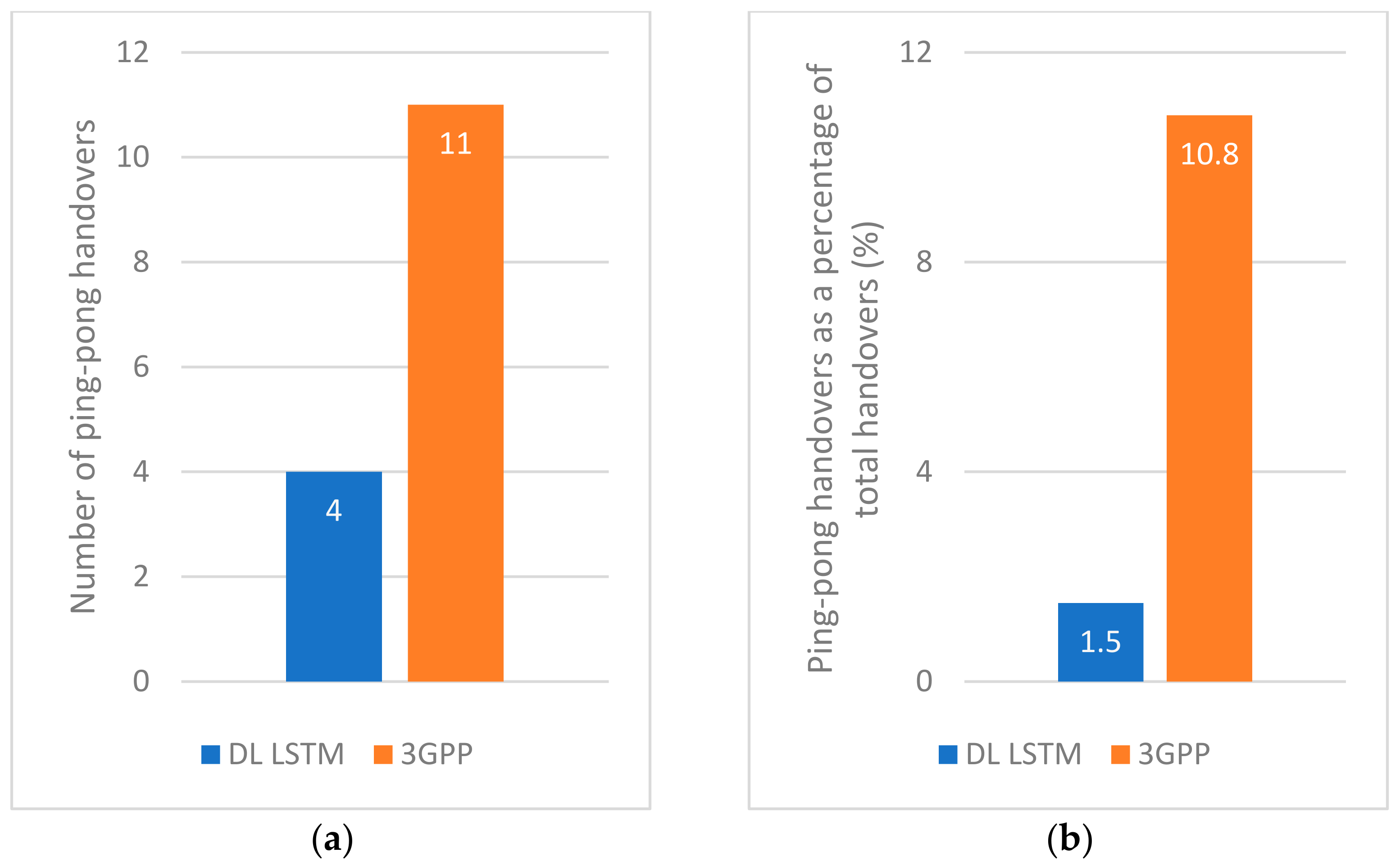
Figure 6a,b shows the number of ping-pong handovers for both algorithms, and their proportion as a percentage of the total handovers, respectively. The results show the proposed algorithm has fewer ping-pong handovers than the 3GPP scheme and much fewer when considered as a percentage of the total handovers. The key feature that contributes to this outcome is the averaging of the CQIs over seven timestamps, therefore mitigating potential ping-pong effects and providing a more stable transition to the desired BS.

7.2.3. Handover Failures

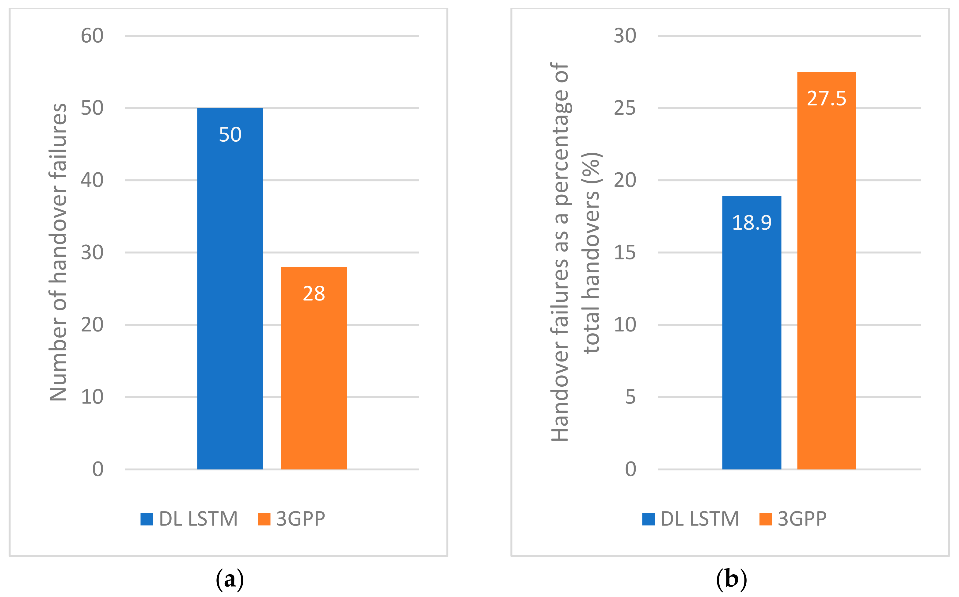
Figure 7a shows the number of HOFs for both algorithms. The result shows that the proposed algorithm has a higher number of HOFs than the 3GPP scheme, which is somewhat unexpected. However, this absolute number of HOFs can be misleading as the proposed algorithm also performed a much higher number of handovers, as explained in Section 7.2.1. Indeed, if we consider the HOFs as a percentage of the total handovers, the proposed algorithm is found to fail 30% less than the 3GPP scheme, as shown in Figure 7b.
This can be attributed to the more confident decision-making by the proposed algorithm as it checks the LUT conditions for the average value of the past seven instances. Additionally, it can be attributed to the faster response of the proposed algorithm to higher mobility UEs due to its variation in the frequency of MRs with mobility.

7.2.4. Average Handover Latency

Figure 8a shows the average latency of successful handovers for both algorithms. The results show the latency of the proposed algorithm is marginally lower than the 3GPP scheme. Since a handover may be attempted multiple times due to retransmission of failed handover communications, we also analyzed the proportion of handovers that made a different number of attempts before they became successful.
Figure 8b shows the percentage of handover attempts after a set number of retransmissions (abbreviated as reTx in the figure). It shows that most of the successful handovers were attempted only once (0 retx) or twice (1 retx) for both algorithms. Despite having a slightly lower proportion of handover that becomes successful after the first attempt (0 retx) than the 3GPP scheme, the proposed algorithm is still found to incur a lower average latency. This may be due to the simultaneous activation of admission control and UE handover procedure by the proposed algorithm as described in Section 5.2.2, which helps to reduce the impact of the handover retransmissions.

7.3. Throughput Performance

7.3.1. Total Throughput

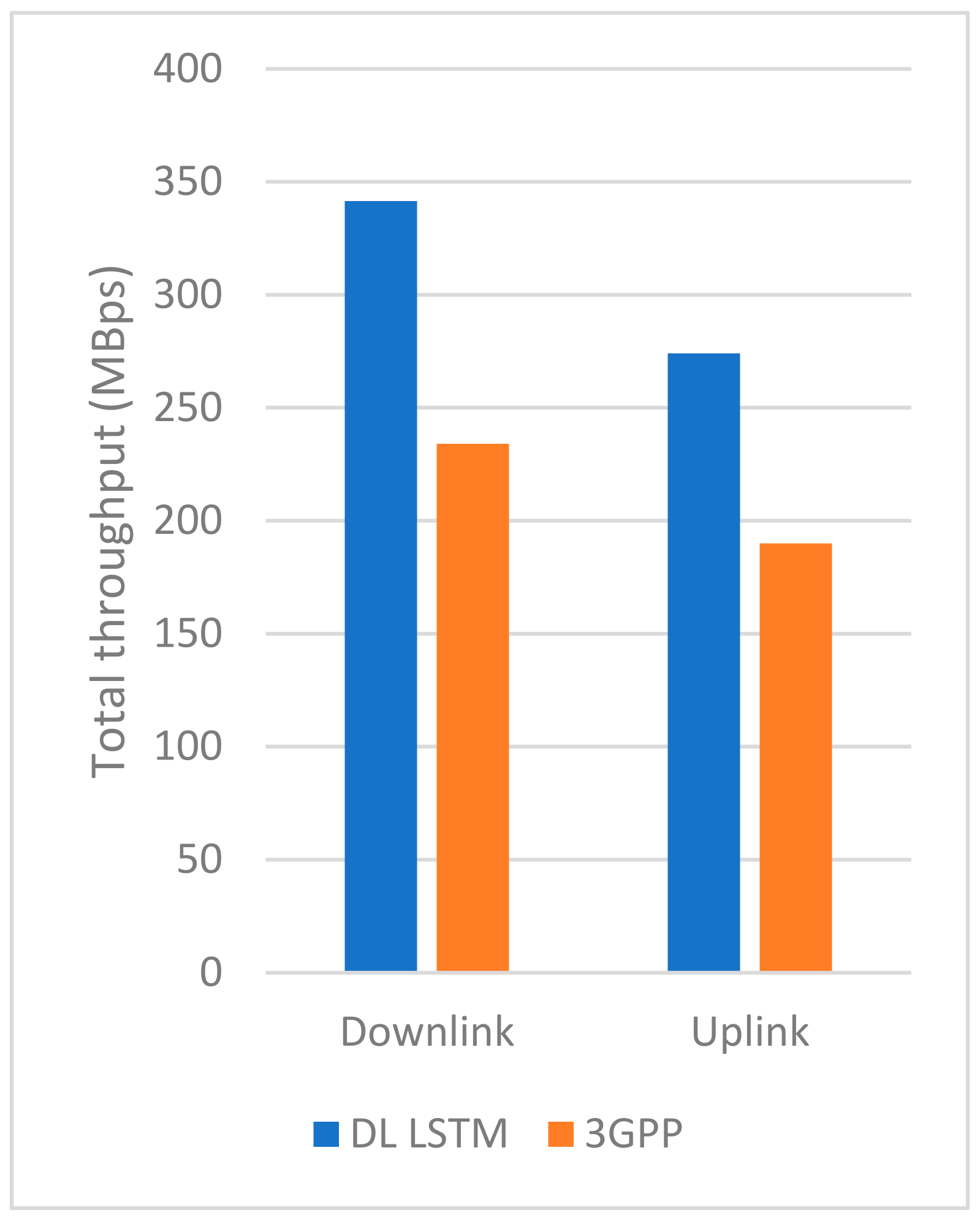
Figure 9 shows the total throughput for the downlink and uplink of both algorithms. The result shows that the proposed algorithm achieves higher throughput by approximately 45% in both downlink and uplink, which is a significant improvement over the 3GPP scheme. This result is expected as the proposed algorithm was designed to provide users with links having the best possible CQI to improve their data rates rather than to simply maintain their connectivity.

7.3.2. Average UE Throughput

Figure 10 shows the average downlink and uplink throughputs of each of the 40 UEs for both algorithms. This result shows that the average UE throughput for the proposed algorithm is generally higher. For example, the 3GPP scheme has 17 UEs with an uplink data rate of below 1 MBps compared to only 9 UEs for the proposed scheme, i.e., a 47% reduction in the number of low throughput users. Similarly, the 3GPP scheme has 16 UEs with a downlink data rate of below 1 MBps compared to only 8 UEs for the proposed scheme, i.e., a 50% reduction in the number of low throughput users. This finding is generally consistent with the total throughput result in Section 7.3.1.

7.3.3. UE Satisfaction Rate

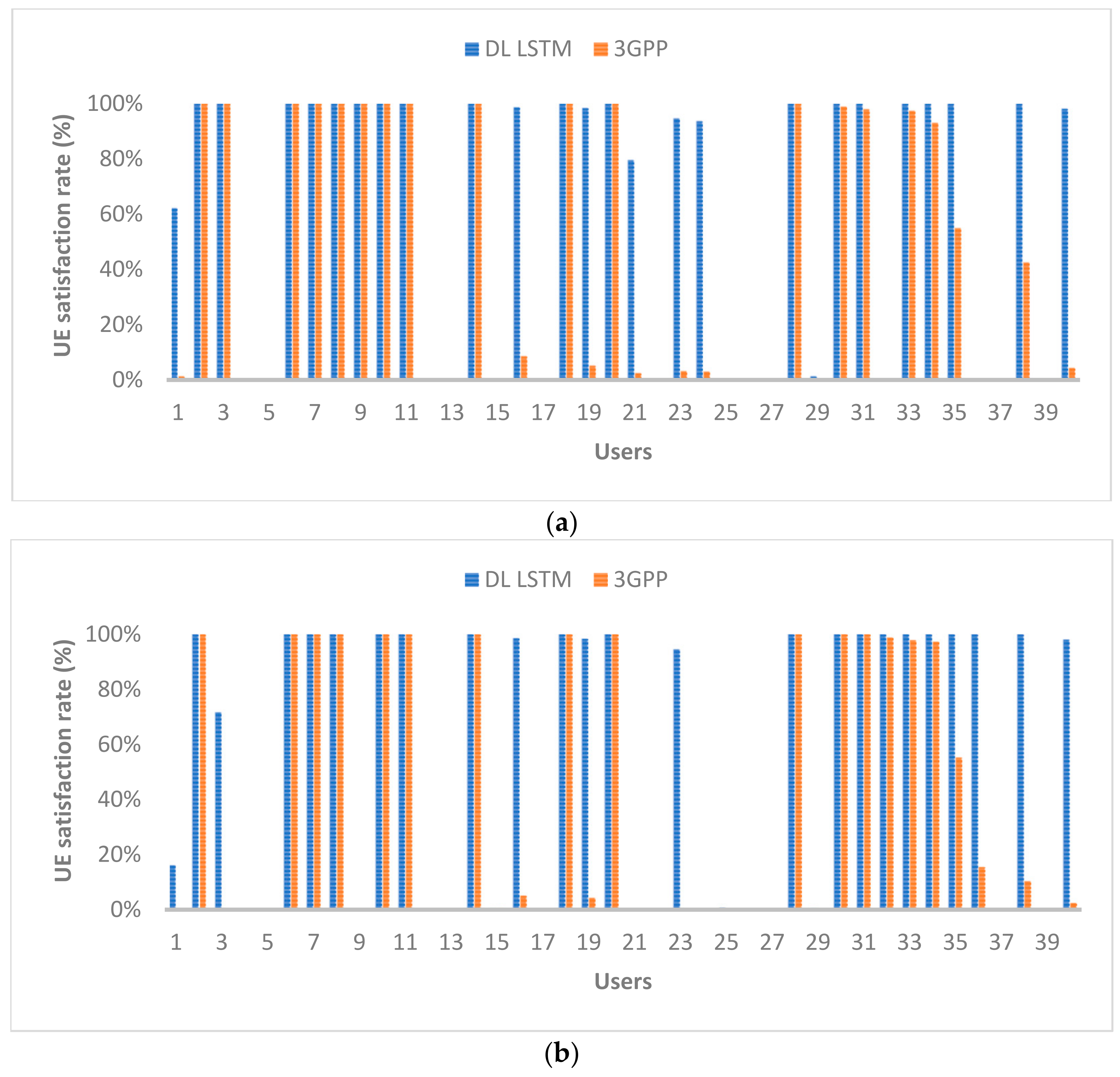
Finally, Figure 11 shows the UE satisfaction rate for both algorithms. It refers to the percentage of time that the data rate requirement for each UE is met. The result clearly shows that a larger number of UEs are satisfied by the proposed algorithm is compared to the 3GPP scheme. If we consider UEs who are satisfied at least 50% of the time with their uplink and downlink data rates, then the proposed algorithm has outperformed the 3GPP scheme by approximately 40%.

8. Conclusions

A DL LSTM handover decision algorithm utilizing LUTs and MEC was proposed, and its impact on UEs and BSs against the benchmark 3GPP scheme was investigated. The results showed that the QoE targets are achieved with improvement in the UE satisfaction rate by 40% over the 3GPP scheme. By replacing the TTT with a dynamic triggering function, the proposed algorithm provided a very fast response to UE mobilities when the LUT requirements were met. This allowed the QoS targets to be met with lower HOF and ping-pong rates than the benchmark by 30% and 86%, respectively. These performance gains are achieved despite a higher occurrence of handovers. This is due to the algorithm attempting to accommodate user data rate requirements and/or user CQI expectations. Furthermore, the proposed modification to the admission control process resulted in handovers with lower latencies that approach the user plane eMBB latency target. As future work, we plan to extend our approach to enhancing inter-RAT handovers as coexistence between legacy and successor systems has always been a requirement in different generations of cellular networks. We also plan to use reinforcement learning to make our LSTM models autonomously adaptive to changing future environments and user requirements.

Author Contributions

Conceptualization, P.K. and B.-C.S.; methodology, B.-C.S.; software, P.K.; validation, P.K. and B.-C.S.; formal analysis, P.K.; investigation, P.K.; resources, B.-C.S.; data curation, P.K.; writing—original draft preparation, P.K.; writing—review and editing, B.-C.S.; visualization, P.K.; supervision, B.-C.S.; project administration, B.-C.S.; All authors have read and agreed to the published version of the manuscript.

Funding

This research received no external funding.

Institutional Review Board Statement

Not applicable.

Informed Consent Statement

Not applicable.

Data Availability Statement

The data that support the findings of this study are available from the authors upon reasonable request.

Conflicts of Interest

The authors declare no conflict of interest.

Nomenclature

3GPP3rd Generation Partnership Project
4G/5G4th/5th Generation
AIArtificial Intelligence
AMFAccess and Mobility Management Function
BBUBase Band Unit
BSBase Station
CoMPCoordinted Multi-Point
CQIChannel Quality Information
DLDeep Learning
DRDate Rate
DRRDate Rate Ratio
EACEarly Admission Control
eMBBEnhanced Mobile Broadband
FDDFrequency Division Duplexing
gNBNext-generation NodeB
GPSGlobal Positioning System
GRUGated Recurrent Unit
HCSNetHeterogeneous Cloud Small Cell Network
HOFHandover Failure
LOSLine-of-Sight
LSTMLong-Short Term Memory
LTELong Term Evolution
LUTLook-Up Table
MBpsMega Bytes per second
MECMulti-access Edge Computing
MLMachine Learning
mmAPMillimeter-wave Access Point
MRMeasurement Report
NFVNetwork Function Virtualization
NLOSNon-Line of Sight
NYUNew York University
QoEQuality of Experience
QoSQuality of Service
RANRadio Access Network
RATRadio Access Technology
reTXRetransmission
RNNRecurrent Neural Network
RSRPReference Signal Received Power
RSSReceived Signal Strength
RSURoad Side Unit
RXReceive
TOPSISTechnique for Order Preference by Similarity to Ideal Solution
TTTTime-to-trigger
TXTransmit
UEUser Equipment
UPFUser Plane Function
URLLCUltra-Reliable Low Latency Communication
VARVector Autoregression

References

  1. Samon, B. Setting the Scene for 5G: Opportunities and Challenges; The International Telecommunication Union: Cham, Switzerland, 2018. [Google Scholar]
  2. Ahmadi, S. 5G NR: Architecture, Technology, Implementation, and Operation of 3GPP New Radio Standards; Academic: New York, NY, USA, 2019. [Google Scholar]
  3. 3GPP. TS 38.300—NR; NR and G-RAN Overall Description; 3GPP: Sophia Antipolis, France, 2020. [Google Scholar]
  4. 3GPP. TS 38.104—NR; Base Station (BS) Radio Transmission and Reception; 3GPP: Sophia Antipolis, France, 2020. [Google Scholar]
  5. 3GPP. TS 36.873—Study on 3D Channel Model for LTE; 3GPP: Sophia Antipolis, France, 2018. [Google Scholar]
  6. Nokia. Open RAN Explained. 2020. Available online: www.nokia.com/about-us/newsroom/articles/open-ran-explained (accessed on 12 November 2021).
  7. 3GPP. TS 23.501—System Architecture for the 5G System (5GS); 3GPP: Sophia Antipolis, France, 2020. [Google Scholar]
  8. 3GPP. TS 38.331—NR; Radio Resource Control (RRC); Protocol Specification; 3GPP: Sophia Antipolis, France, 2021. [Google Scholar]
  9. Jupiter Networks. Distributed Data Centers within the Juniper Networks Mobile Cloud Architecture. White Paper. June 2017. Available online: www.juniper.net/documentation/en_US/design-and-architecture/mobile-cloud/information-products/topic-collections/mca-data-centers-wp.pdf (accessed on 12 November 2021).
  10. ITU. Minimum Requirements Related to Technical Performance for IMT-2020 Radio Interface(s); ITU: Geneva, Switzerland, 2017. [Google Scholar]
  11. Hochreiter, S.; Schmidhuber, J. Long Short-Term Memory. Neural Comput. 1997, 9, 1735–1780. [Google Scholar] [CrossRef] [PubMed]
  12. Olah, C. Understanding LSTM Networks. August 2015. Available online: colah.github.io/posts/2015-08-Understanding-LSTMs/ (accessed on 12 November 2021).
  13. Gers, F.A.; Schmidhuber, J. Recurrent nets that time and count. In Proceedings of the International Joint Conference on Neural Networks (IJCNN), Como, Italy, 24–27 July 2000. [Google Scholar]
  14. Cho, K.; Bahdanau, D.; Bougares, F.; Schwenk, H.; Bengio, Y. Learning Phrase Representations using RNN Encoder–Decoder for statistical machine translation. In Proceedings of the Conference on Empirical Methods in Natural Language Processing, Dohar, Qatar, 25–29 October 2014. [Google Scholar]
  15. Zhao, F.; Tian, H.; Nie, G.; Wu, H. Received Signal Strength Prediction Based Multi-Connectivity Handover Scheme for Ultra-Dense Networks. In Proceedings of the 24th Asia-Pacific Conference on Communications (APCC), Ningbo, China, 12–14 November 2018. [Google Scholar]
  16. Polese, M.; Giordani, M.; Mezzavilla, M.; Rangan, S.; Zorzi, M. Improved Handover through Dual Connectivity in 5G mm Wave Mobile Networks. IEEE J. Sel. Areas Commun. 2017, 35, 2069–2084. [Google Scholar] [CrossRef] [Green Version]
  17. Evangeline, S.C.; Kumaravelu, V.B. Decision Process for Vertical Handover in Vehicular Adhoc Networks. In Proceedings of the International Conference on Microelectronic Devices, Circuits and Systems (ICMDCS), Vellore, India, 10–12 August 2017. [Google Scholar]
  18. Da Costa Silva, K.; Becvar, Z.; Renato Lisboa Frances, C. Adaptive Hysteresis Margin Based on Fuzzy Logic for Handover in Mobile Networks with Dense Small Cells. IEEE Access 2018, 6, 17178–17189. [Google Scholar] [CrossRef]
  19. Castro-Hernandez, D.; Paranjape, R. Optimization of Handover Parameters for LTE/ LTE-A in-Building Systems. IEEE Trans. Veh. Technol. 2018, 67, 5260–5273. [Google Scholar] [CrossRef]
  20. Shubyn, B.; Lutsiv, N.; Syrotynskyi, O.; Kolodii, R. Deep Learning based Adaptive Handover Optimization for Ultra-Dense 5G Mobile Networks. In Proceedings of the IEEE 15th International Conference on Advanced Trends in Radioelectronics, Telecommunications and Computer Engineering (TCSET), Lviv-Slavske, Ukraine, 25–29 February 2020. [Google Scholar]
  21. Bahra, N.; Pierre, S. A Hybrid User Mobility Prediction Approach for Handover Management in Mobile Networks. Telecom 2021, 2, 199–212. [Google Scholar] [CrossRef]
  22. Zhang, H.; Jiang, C.; Cheng, J.; Leung, V.C.M. Cooperative Interference Mitigation and Handover Management for Heterogeneous Cloud Small Cell Networks. IEEE Wirel. Commun. 2015, 22, 92–99. [Google Scholar] [CrossRef] [Green Version]
  23. Kolding, T.; Gimenez, L.C.; Pedersen, K.I. Optimizing Synchronous Handover in Cloud RAN. In Proceedings of the IEEE Conference on Vehicular Technology (VTC), Toronto, ON, Canada, 24–27 September 2017. [Google Scholar]
  24. Zhou, P.; Finley, B.; Li, X.; Tarkoma, S.; Kangasharju, J.; Ammar, M.; Hui, P. 5G MEC Computation Handoff for Mobile Augmented Reality. arXiv 2021, arXiv:2101.00256. [Google Scholar]
  25. Brown, G. New Transport Network Architectures for 5G RAN. Heavy Reading. Available online: www.fujitsu.com/us/Images/New-Transport-Network-Architectures-for-5G-RAN.pdf (accessed on 12 November 2021).
  26. Chávez, M.L. Chapter 6—Communication Network Architecture. In Fieldbus Systems and Their Applications 2005; Elsevier: Amsterdam, The Netherlands, 2006; pp. 107–114. [Google Scholar]
  27. 3GPP. TS 38.133—NR; Requirements for Support of Radio Resource Management; 3GPP: Sophia Antipolis, France, 2021. [Google Scholar]
  28. Muller, M.K.; Ademaj, F.; Dittrich, T.; Fastenbauer, A.; Elbal, B.R.; Nabavi, A.; Nagel, L.; Schwarz, S.; Rupp, M. Flexible multi-node simulation of cellular mobile communications: The Vienna 5G System Level Simulator. EURASIP J. Wirel. Commun. Netw. 2018, 1, 227. [Google Scholar] [CrossRef] [Green Version]
  29. MathWorks. 5G Toolbox. 2020. Available online: au.mathworks.com/products/5g.html (accessed on 12 November 2021).
  30. MathWorks. Automated Driving Toolbox. 2020. Available online: au.mathworks.com/products/automated-driving.html (accessed on 12 November 2021).
  31. MathWorks. Deep Learning Toolbox. 2020. Available online: au.mathworks.com/products/deep-learning.html (accessed on 12 November 2021).
  32. Goodfellow, I.; Bengio, Y.; Courville, A. Chapter 5—Machine Learning Basics. In Deep Learning; MIT Press: Cambridge, MA, USA, 2016; p. 110. [Google Scholar]
Figure 1. Edge (MEC) and Central (Cloud) data centers.
Telecom 02 00026 g001
Figure 2. Three-tier 5G RAN architecture with MEC deployment.
Telecom 02 00026 g002
Figure 3. Flow diagram of the modified handover preparation phase.
Telecom 02 00026 g003
Figure 4. (a) Vertical and oblique aerial views of the NYU campus; (b) Corresponding views of the simulated environment modeled after the NYU campus.
Telecom 02 00026 g004
Figure 5. (a) Total number of handovers and (b) number of triggering events.
Telecom 02 00026 g005
Figure 6. (a) Number of ping-pong handovers and (b) ping-pong handovers as a percentage of total handovers.
Telecom 02 00026 g006
Figure 7. (a) Number of handover failures and (b) handover failures as a percentage of total handovers.
Telecom 02 00026 g007
Figure 8. (a) Average handover latency and (b) percentage of handover attempts.
Telecom 02 00026 g008
Figure 9. Total throughput.
Telecom 02 00026 g009
Figure 10. Average UE throughput for (a) downlink and (b) uplink.
Telecom 02 00026 g010
Figure 11. UE satisfaction for (a) downlink and (b) uplink.
Telecom 02 00026 g011
Table 1. Handover trigger events for intra-RAT handover.
Event Description
A1Serving cell becomes better than a threshold
A2Serving becomes worse than a threshold
A3Neighbor becomes offset better than serving
A4Neighbor becomes better than a threshold
A5Serving cell becomes worse than threshold 1, and neighboring cell becomes better than threshold 2
A6Neighbor become offset better than secondary cell
Table 2. Event parameter ranges.
EventParameterMinimumMaximum
A1, A2, A4, A5RSRP threshold−156 dBm−31 dBm
AllHysteresis0 dB15 dB
A3, A6Offset−15 dB+15 dB
Table 3. Summary of related works.
ApproachRef.Solution SummaryBenefits and Drawbacks
Multi-connectivity[15]
  • Proposes to always connect UE to two 5G mm-wave access points and one LTE BS to reduce HO latency and signaling overhead
Benefits:
  • Reduced number of HOs and HO latency
  • Increase throughput
Drawbacks:
  • High signaling overhead
  • Inefficient use of radio resources
  • No comprehensive study of multi-tier HOs despite having a two-tier scenario
  • Focuses mainly on one tier and uses the other tier as a fall-back system
[16]
  • Proposes a dual-connectivity solution that connects UE to both 4G LTE and 5G mm-wave BSs
  • This mitigates issue of mm-waves being susceptible to blockages and degradation in channel quality
[17]
  • Proposes HO decision scheme for vehicles based on geometrically calculated cell coverage, vehicle trajectory, and HO latency
  • Uses soft HO between RSUs and hard HO between RSU and BS
AI-based[18]
  • Proposes to use fuzzy logic to reduce redundant HOs and HOF rates in dense small cell networks
  • Analyzes UE velocity and radio channel quality to adapt hysteresis margins for HO decisions
Benefits:
  • Reduced HOs, HOF, and ping-pong rates
Drawbacks:
  • No latency, throughput results
  • High computational load
[19]
  • Proposes to use ML and data mining techniques to learn and identify cell characteristics and then optimize the HO parameters for in-building BSs
  • The considered HO parameters are A2 and A3 handover thresholds, and TTT period
Benefits:
  • Good throughput
  • Low latency
Drawbacks:
  • No results on HOF, number of HOs, and ping-pong rates
  • Only focused on exiting UEs
[20]
  • Proposes a GRU-based scheme to predict the number of users in a cell for a given time of day
  • The prediction is used for varying cell sizes, making it easier for UEs to be handed over to underloaded cells or harder for UEs to connect to overloaded cells
Benefits:
  • Predict up to 90% accuracy
  • Cell sizes variable for more balanced loading
Drawbacks:
  • When all cells overloaded, radio link failures increase
  • Need plenty of data to learn
  • Lower accuracy than LSTMs
[21]
  • Proposes a hybrid VAR-GRU scheme to predict the future trajectories of users in a mobile network
  • The prediction is applied to HO management to reduce HO processing and transmission costs
Benefits:
  • Higher prediction accuracy than GRU, RNN, and LSTM
Drawbacks:
  • No consideration of propagation effects and interferences on user connectivity
Cloud/Edge-based[22]
  • Proposes a CoMP transmission scheme and a HO management scheme for HCSNets with macro and small cells
  • Determines if UEs can handover from macro to small cells based on their speed/latency requirements
Benefits:
  • Less HO signaling overhead
Drawbacks:
  • No other metrics evaluated
  • Mainly focuses on macro-to-small cell HOs
[23]
  • Proposes an EAC scheme for reducing HO preparation time in cloud RAN
  • Focuses on synchronous HO that enables predictable and fast HO to support URLLC services in high mobility applications
Benefits:
  • Reduced HO preparation time and overall latency
Drawbacks:
  • Only uses cloud; may improve latency by utilizing MEC
[24]
  • Proposes a HO algorithm for users of MAR applications in 5G-MEC network
  • Jointly considers RSS of BSs and computation load of co-located MEC servers
Benefits:
  • Reduced UE experienced delay
Drawbacks:
  • Potential performance tradeoff between MEC and non-MEC applications
Table 4. A1 and A3 handover conditions.
A3 EventA1 Event
target gNB RSS > source gNB RSS + A3 offset (3 dB)source gNB RSS > A1 threshold (minimum RSS for a CQI of 1)
Table 5. DL LSTM classification categories.
DimensionClassificationLetter CodeValue Range
User CQIGoodGCQI > 5
OkO3 < CQI ≤ 5
PoorPCQI ≤ 2
User DRRMetMDRR ≥ 1
Not MetNDRR < 1
User DirectionCloserCΔ RSS ≥ 0 dBm
AwayAΔ RSS < 0 dBm
User SpeedFastF|Δ RSS| ≥ 5 dBm
LowL|Δ RSS| < 5 dBm
Table 6. All 24 classification of the proposed DL LSTM.
IndexCodeClassification
CQIDRRDirectionSpeed
1GMCFGoodMetCloserFast
2GMCLLow
3GMAFAwayFast
4GMALLow
5GNCFNot metCloserFast
6GNCLLow
7GNAFAwayFast
8GNALLow
9OMCFOkMetCloserFast
10OMCLLow
11OMAFAwayFast
12OMALLow
13ONCFNot metCloserFast
14ONCLLow
15ONAFAwayFast
16ONALLow
17PMCFPoorMetCloserFast
18PMCLLow
19PMAFAwayFast
20PMALLow
21PNCFNot metCloserFast
22PNCLLow
23PNAFAwayFast
24PNALLow
Table 7. LUT for handover decisions based on DL LSTM classifications.
Classification for Potential BSParameters of Current BS
DR MetDR Not Met
CQI < 3CQI ≥ 3CQI < 3CQI ≥ 3
GMCF1011
GMCL1011
GMAF1011
GMAL1011
GNCF1010
GNCL1010
GNAF1010
GNAL1010
OMCF1011
OMCL1011
OMAF1010
OMAL1011
ONCF1010
ONCL1010
ONAF1010
ONAL1010
PMCF1*01*0
PMCL1*01*0
PMAF0000
PMAL0000
PNCF1*01*0
PNCL1*01*0
PNAF0000
PNAL0000
Table 8. BS simulation parameters.
ParametersMacro Cell (Wide Area BS)Micro/Pico Cell (Medium Area BS)Femtocell
(Local Area BS)
Number of BSs24324
BS coverage range500–1000 m50–100 m10–20 m
BS height50 m10 m6.5 m
Min distance to UE35 m5 m2 m
Carrier frequency2.0 GHz3.5 GHz26 GHz
Bandwidth20 MHz40 MHz
Duplex modeFDD
Transmit power40 W6.31 W0.25 W
Antenna gain0 dBi
Number of antennas1 TX/RX pair
Pathloss model (LOS/NLOS)3D-UMa3D-UMiFree-space + other loss factors *
Shadow fading4 dB
Wall losses 13 dB
* Wall losses, shadow fading, and user noise interferences.
Table 9. UE simulation parameters.
ParametersMotoristsCyclistsPedestrians
Number of UEs22414
Speeds0−80 km/h0−20 km/h0−5 km/h
Channel modelVehicle ATypical UrbanTypical Urban
Number of antennas2 TX/RX pairs (one operates at 2/3.5 GHz; the other at 26 GHz)
Transmit power1 W
Table 11. Effects of the number of epochs (20 hidden units).
Number of EpochsLearning Time (s)Prediction Accuracy (%)
Run 1Run 2Run 3MeanRun 1Run 2Run 3Mean
10444422.128.1719.8616.72
1003734343557.0367.8954.1759.70
100035235336035599.4599.8699.4799.59
200071081973975690.0590.6899.3593.36
Publisher’s Note: MDPI stays neutral with regard to jurisdictional claims in published maps and institutional affiliations.