
Wearable Flexible Antenna for UWB On-Body and Implant Communications


Abstract
1. Introduction
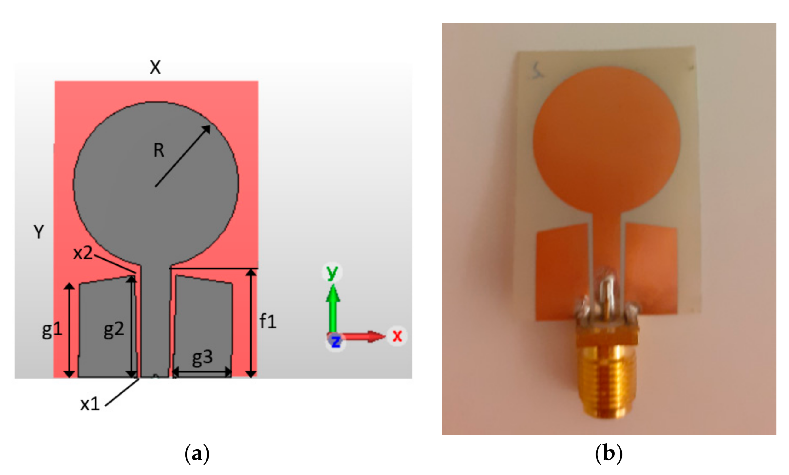
2. Antenna Model and Prototype
3. Methodology
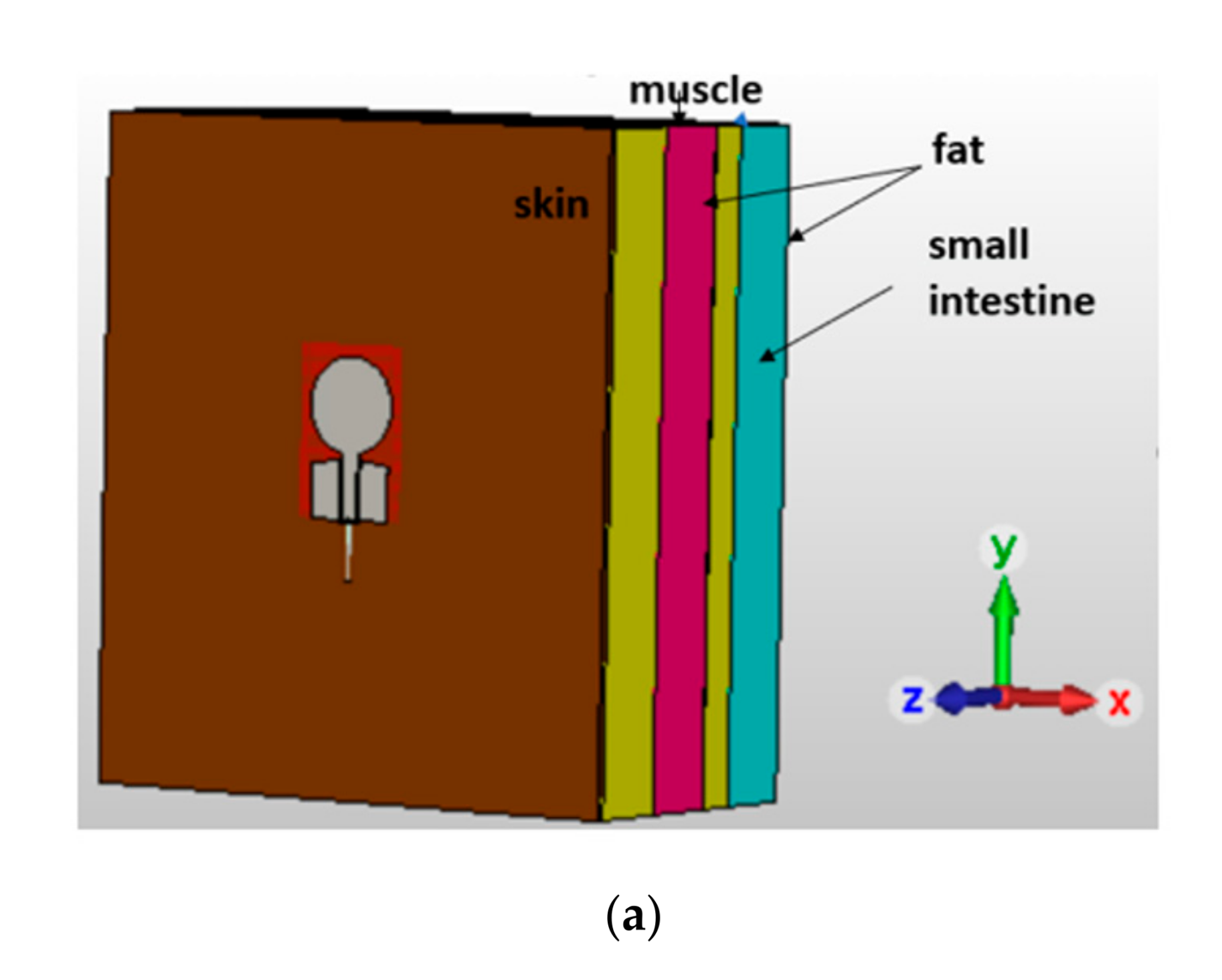
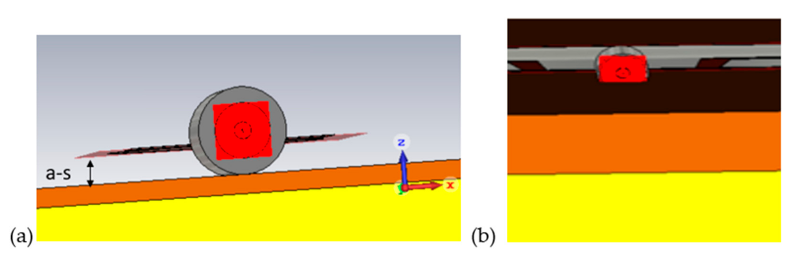
3.1. Simulations
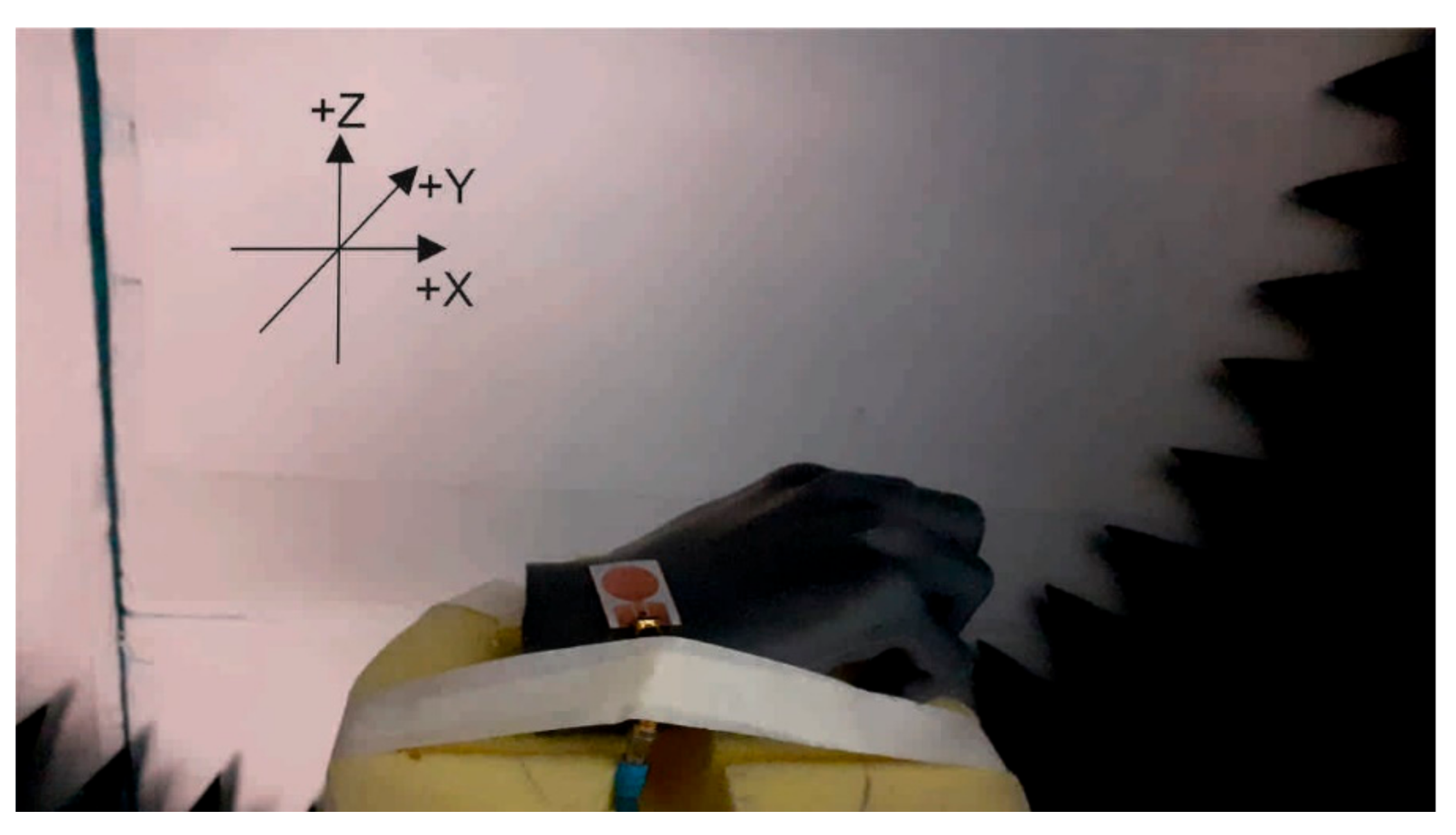
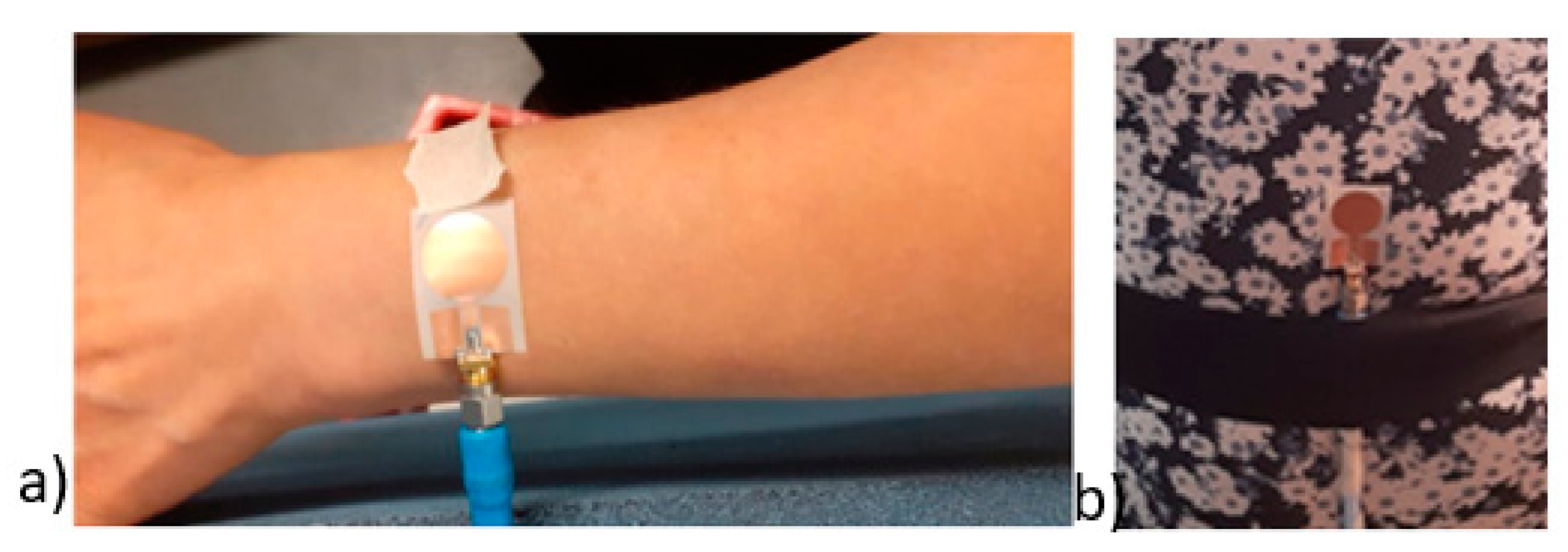
3.2. Measurements
4. Results
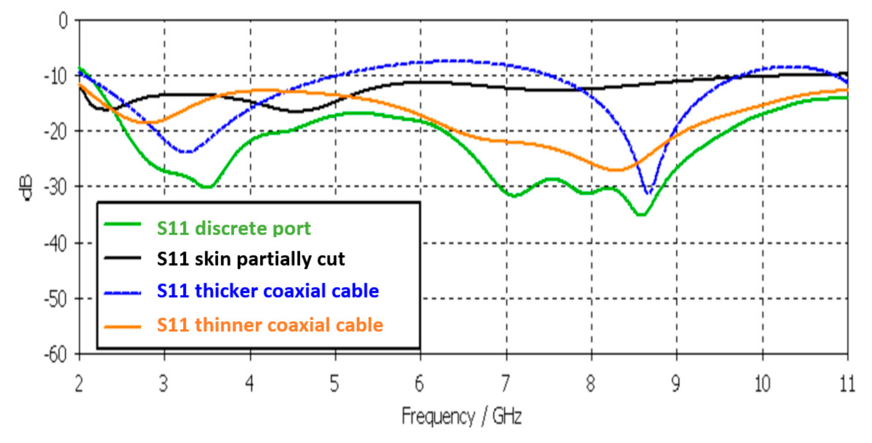
4.1. Simulated S11 Parameters
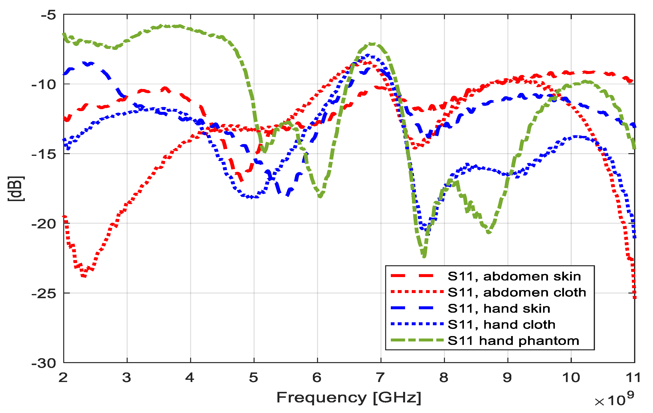
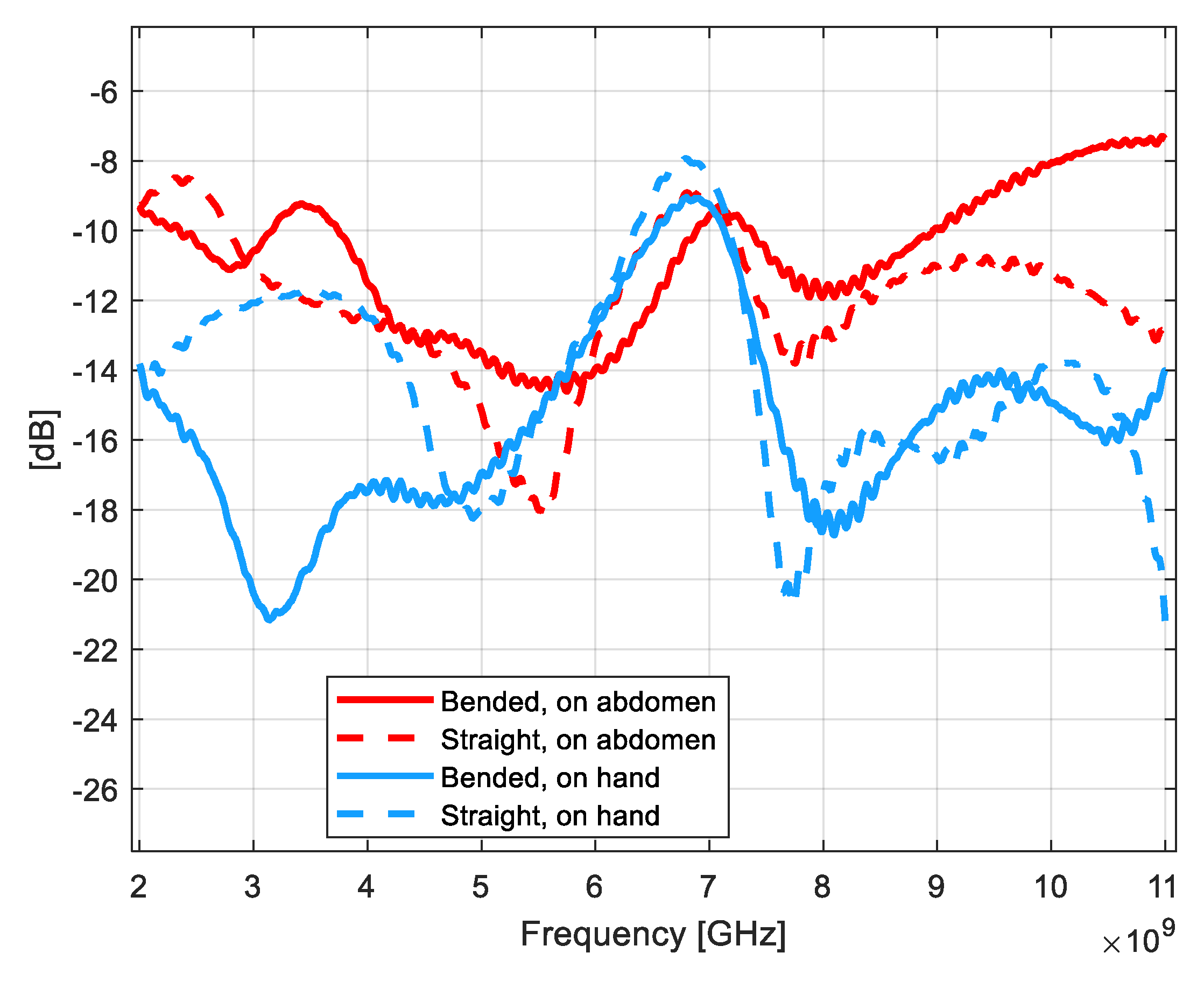
4.2. Measured S11 Parameters
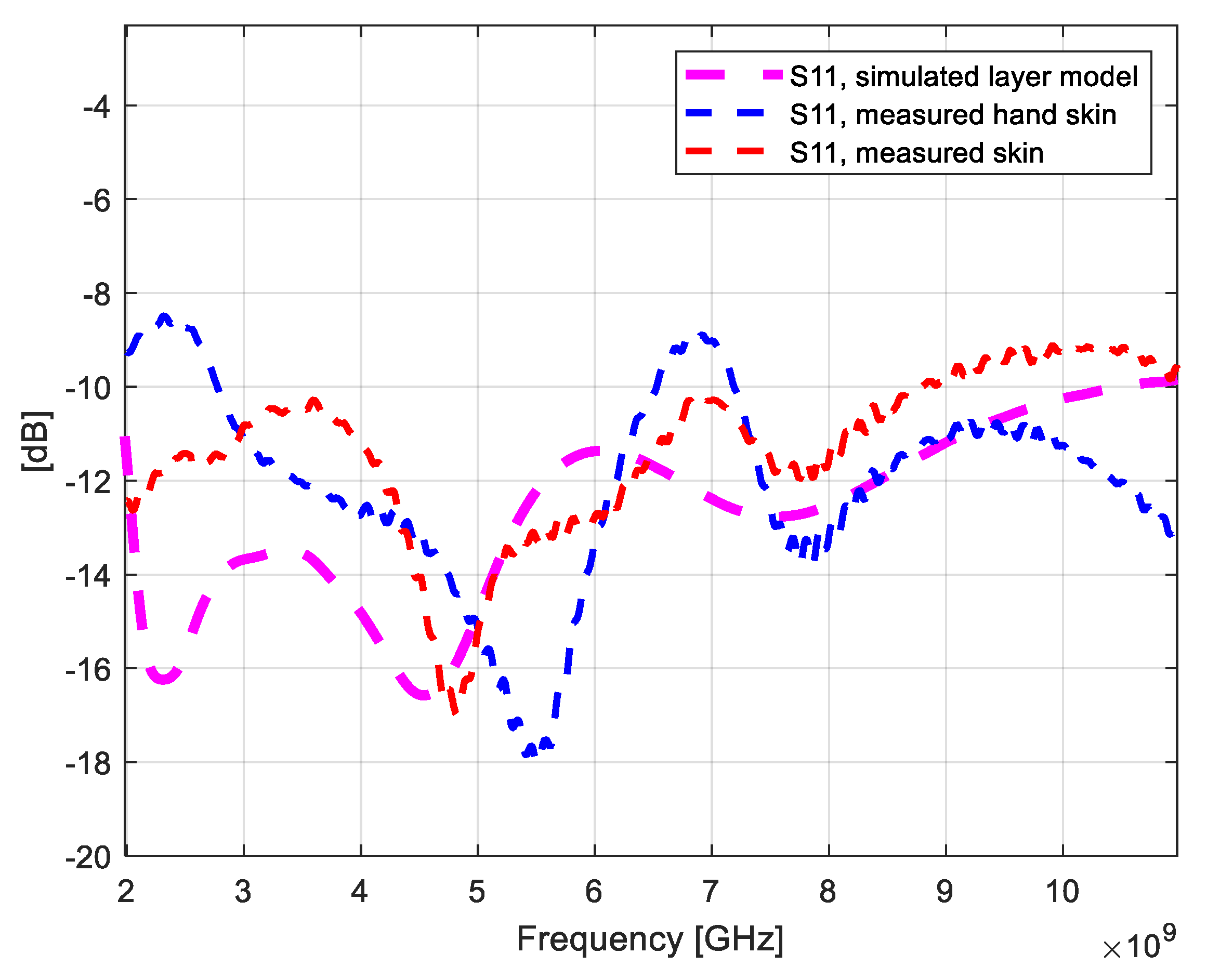
4.3. Comparison of Simulated and Measured Results for S11 Parameter and Antenna’s Total Efficiency
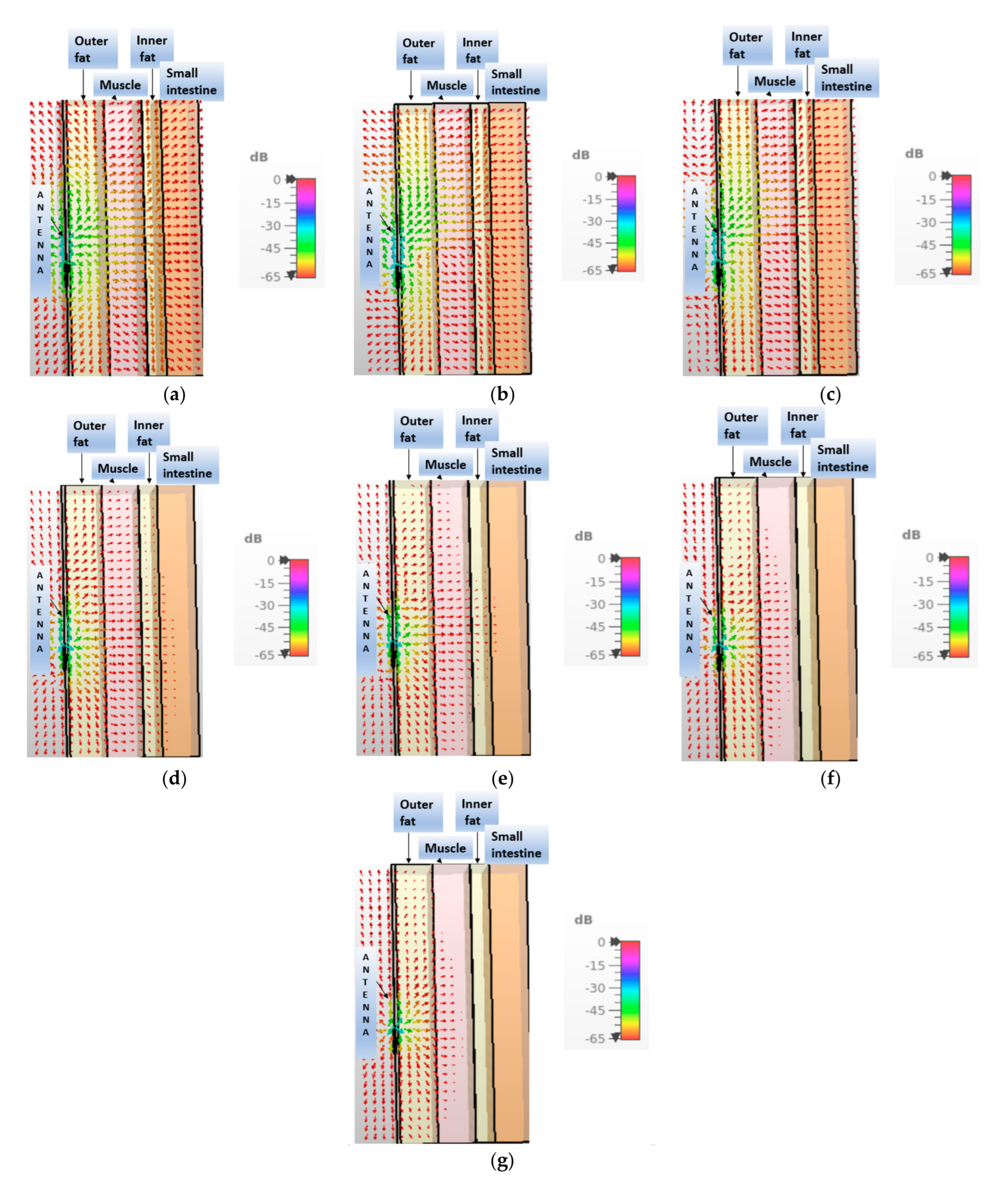
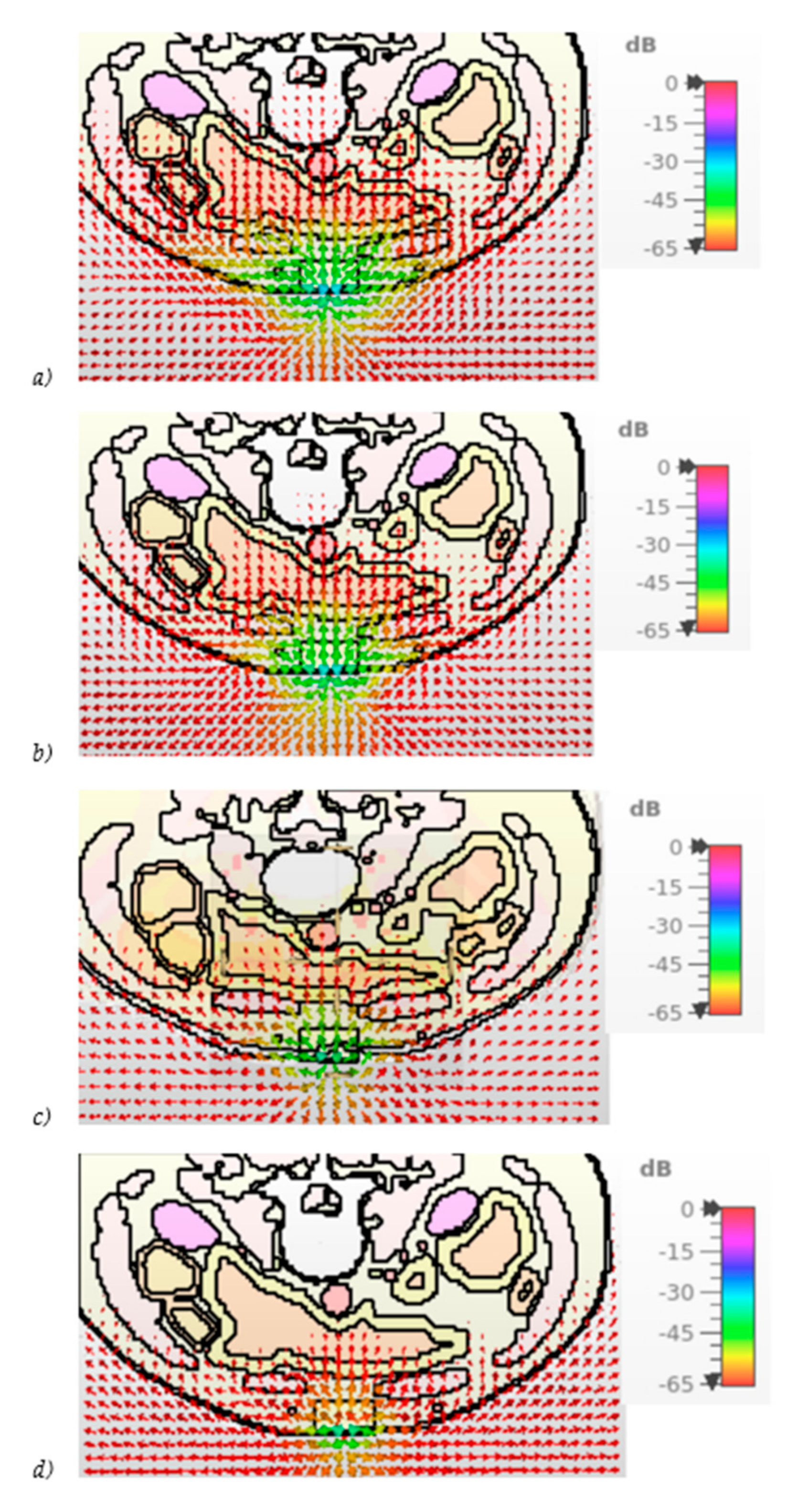
4.4. Power Flow Analysis at Different Frequencies for Layer Model
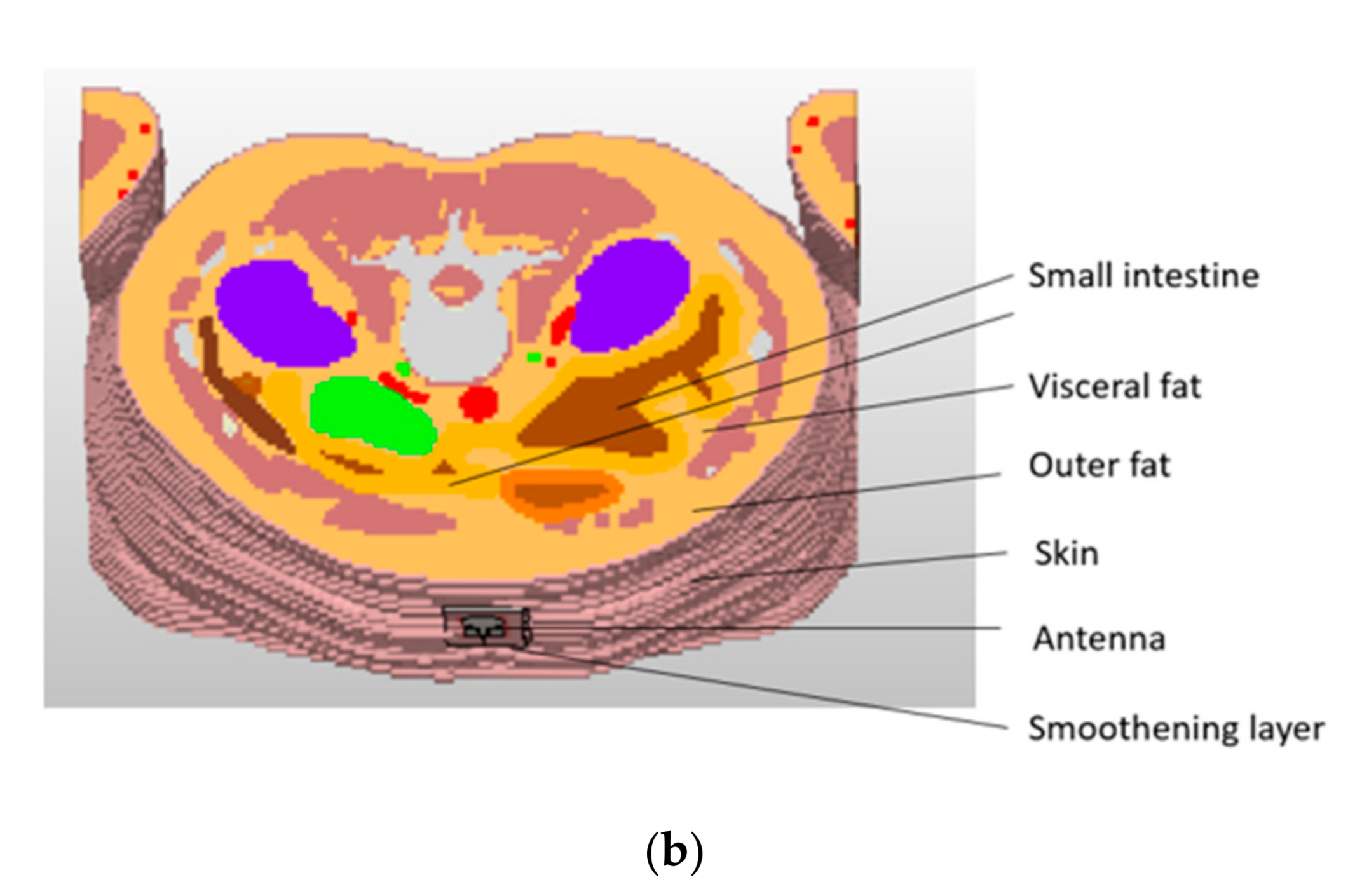
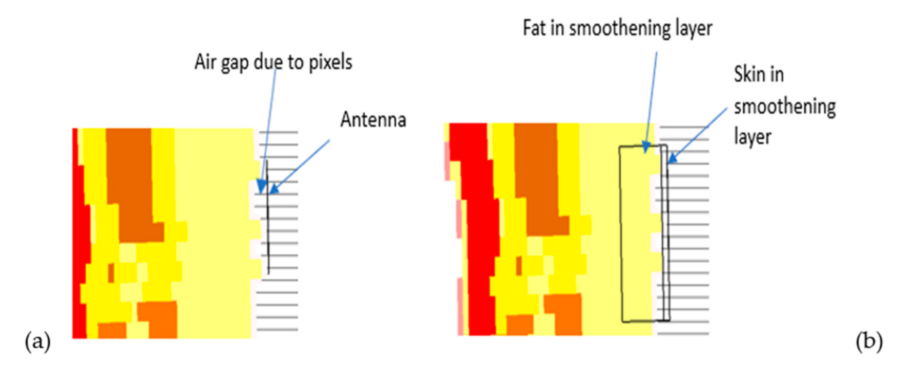
4.5. Power Flow Analysis at Different Frequencies for Voxel Models
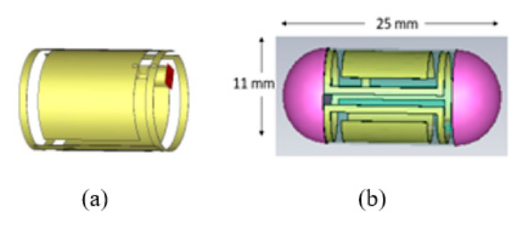
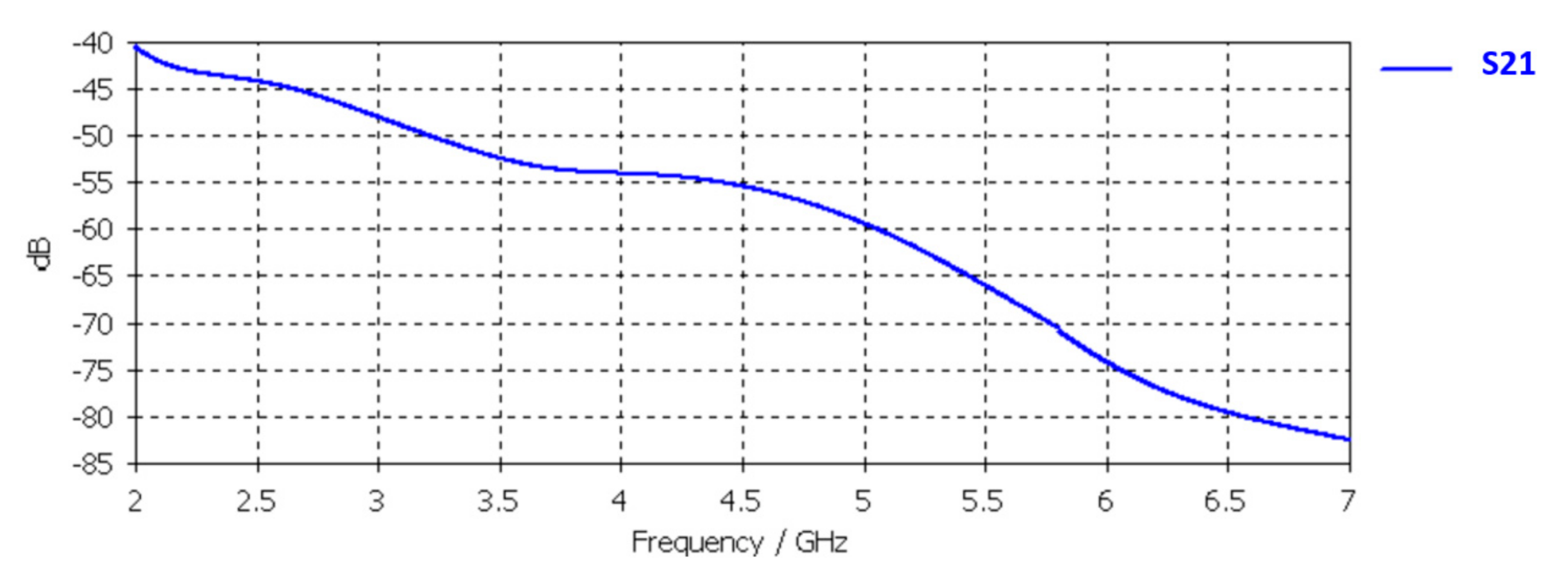
4.6. Channel Evaluations between the Flexible Antenna and UWB Capsule Endoscope Model
4.7. SAR Evaluations
5. Discussion
Author Contributions
Funding
Institutional Review Board Statement
Informed Consent Statement
Data Availability Statement
Acknowledgments
Conflicts of Interest
References
- Paolini, G.; Masotti, D.; Antoniazzi, F.; Cinotti, T.S.; Costanzo, A. Fall Detection and 3-D Indoor Localization by a Custom RFID Reader Embedded in a Smart e-Health Platform. IEEE Trans. Microw. Theory Tech. 2019, 67, 5329–5339. [Google Scholar] [CrossRef]
- Xu, L.-J.; Duan, Z. Differentially fed metal frame antenna with common mode suppression for biomedical smartband appli-cations. Radio Sci. 2018, 53, 485–495. [Google Scholar] [CrossRef]
- Li, Y.; Zhang, M. Study on a Cylindrical Sensor Network for Intelligent Health Monitoring and Prognosis. IEEE Access 2018, 6, 69195–69202. [Google Scholar] [CrossRef]
- Srivastava, A.; Sankar, N.K.; Chatterjee, B.; Das, D.; Ahmad, M.; Kukkundoor, R.K.; Saraf, V.; Ananthapadmanabhan, J.; Sharma, D.K.; Baghini, M.S. Bio-WiTel: A Low-Power Integrated Wireless Telemetry System for Healthcare Applications in 401–406 MHz Band of MedRadio Spectrum. IEEE J. Biomed. Health Inform. 2018, 22, 483–494. [Google Scholar] [CrossRef] [PubMed]
- Wang, C.; Chen, S.; Yang, Y.; Hu, F.; Liu, F.; Wu, J. Literature review on wireless sensing-Wi-Fi signal-based recognition of human activities. Tsinghua Sci. Technol. 2018, 23, 203–222. [Google Scholar] [CrossRef]
- Bresnahan, D.; Li, Y. Investigation of Creeping Wave Propagation Around the Human Head at ISM Frequencies. IEEE Antennas Wirel. Propag. Lett. 2017, 16, 2767–2770. [Google Scholar] [CrossRef]
- Teshome, A.K.; Kibret, B.; Lai, D.T.H. A Review of Implant Communication Technology in WBAN: Progress and Challenges. IEEE Rev. Biomed. Eng. 2018, 12, 88–99. [Google Scholar] [CrossRef] [PubMed]
- Haghi, M.; Stoll, R.; Thurow, K. Pervasive and Personalized Ambient Parameters Monitoring: A Wearable, Modular, and Configurable Watch. IEEE Access 2019, 7, 20126–20143. [Google Scholar] [CrossRef]
- Ahmed, G.; Islam, S.U.; Shahid, M.; Akhunzada, A.; Jabbar, S.; Khan, M.K.; Riaz, M.; Han, K.J. Rigorous Analysis and Evaluation of Specific Absorption Rate (SAR) for Mobile Multimedia Healthcare. IEEE Access 2018, 6, 29602–29610. [Google Scholar] [CrossRef]
- IEEE Standard for Safety Levels with Respect to Human Exposure to Electric, Magnetic, and Electromagnetic Fields, 0 Hz to 300 GHz. In IEEE Std C95.1-2019 (Revision of IEEE Std C95.1-2005/ Incorporates IEEE Std C95.1-2019/Cor 1-2019). 4 October 2019, pp. 1–312. Available online: https://ieeexplore.ieee.org/document/8859679 (accessed on 30 August 2021).
- Federal Communications Commission (FCC). Medical Device Radiocommunications Service (MedRadio). 47 C.F.R, Part 95. Available online: https://www.fcc.gov/medical-device-radiocommunications-service-medradio (accessed on 8 January 2021).
- Dumanli, S. A digitally assisted repeater antenna for implant communications. In Proceedings of the 2017 11th European Conference on Antennas and Propagation (EUCAP), Paris, France, 19–24 March 2017; pp. 181–184. [Google Scholar]
- Kaim, V.; Kanaujia, B.K.; Kumar, S.; Choi, H.C.; Kim, K.W.; Rambabu, K. Ultra-Miniature Circularly Polarized CPW-Fed Implantable Antenna Design and its Validation for Biotelemetry Applications. Sci. Rep. 2020, 10, 1–16. [Google Scholar] [CrossRef]
- Ding, S.; Koulouridis, S.; Pichon, L. Implantable Wireless Transmission Rectenna System for Biomedical Wireless Applications. IEEE Access 2020, 8, 195551–195558. [Google Scholar] [CrossRef]
- Magill, M.K.; Conway, G.A.; Scanlon, W.G. Circularly Polarized Dual-Mode Wearable Implant Repeater Antenna with Enhanced Into-Body Gain. IEEE Trans. Antennas Propag. 2020, 68, 3515–3524. [Google Scholar] [CrossRef]
- Iqbal, A.; Basir, A.; Smida, A.; Khaddaj Mallat, N.; Elfergani, I.; Rodriguez, J.; Kim, S. Electromagnetic Bandgap Backed Millimeter-Wave MIMO Antenna for Wearable Applications. Access IEEE 2019, 7, 111135–111144. [Google Scholar] [CrossRef]
- Kanagasabai, M.; Sambandam, P.; Alsath, M.G.N.; Palaniswamy, S.; Ravichandran, A.; Girinathan, C. Miniaturized Circularly Polarized UWB Antenna for Body Centric Communication. IEEE Trans. Antennas Propag. 2021, 1–8. [Google Scholar] [CrossRef]
- Tak, J.; Woo, S.; Kwon, J.; Choi, J. Dual-Band Dual-Mode Patch Antenna for On-/Off-Body WBAN Communications. IEEE Antennas Wirel. Propag. Lett. 2015, 15, 348–351. [Google Scholar] [CrossRef]
- Kissi, C.; Sarestoniemi, M.; Kumpuniemi, T.; Sonkki, M.; Myllymaki, S.; Srifi, M.N.; Pomalaza-Raez, C. Directive Low-Band UWB Antenna for In-body Medical Communications. IEEE Access 2019, 7, 149026–149038. [Google Scholar] [CrossRef]
- Tuovinen, T.; Berg, M.; Yazdandoost, K.Y.; Iinatti, J. Ultra wideband loop antenna on contact with human body tissues. IET Microwaves, Antennas Propag. 2013, 7, 588–596. [Google Scholar] [CrossRef]
- Zahran, S.R.; Abdalla, M.A.; Gaafar, A. New thin wide-band bracelet-like antenna with low SAR for on-arm WBAN applications. IET Microw. Antennas Propag. 2019, 13, 1219–1225. [Google Scholar] [CrossRef]
- Shay, W.-T.; Jan, S.-C.; Tarng, J.H. A Reduced-Size Wide Slot Antenna for Enhancing Along-Body Radio Propagation in UWB On-Body Communications. IEEE Trans. Antennas Propag. 2013, 62, 1194–1203. [Google Scholar] [CrossRef]
- Kissi, C.; Särestöniemi, M.; Kumpuniemi, T.; Myllymäki, S.; Sonkki, M.; Mäkelä, J.-P.; Nabil Srifi, M.; Jantunen, H.; Pomala-za-Raez, C. Receiving UWB antenna for wireless capsule endoscopy communications. Prog. Electromagn. Res. C 2020, 101, 53–69. [Google Scholar] [CrossRef]
- Blauert, J.; Kiourti, A. Bio-Matched Horn: A Novel 1–9 GHz On-Body Antenna for Low-Loss Biomedical Telemetry with Implants. IEEE Trans. Antennas Propag. 2019, 67, 5054–5062. [Google Scholar] [CrossRef]
- Shang, J.; Yu, Y. An Ultrawideband Capsule Antenna for Biomedical Applications. IEEE Antennas Wirel. Propag. Lett. 2019, 18, 2548–2551. [Google Scholar] [CrossRef]
- Kirtania, S.G.; Elger, A.W.; Hasan, R.; Wisniewska, A.; Sekhar, K.; Karacolak, T.; Sekhar, P.K. Flexible Antennas: A Review. Micromachines 2020, 11, 847. [Google Scholar] [CrossRef] [PubMed]
- Jahnavi, R.; Choudhary, A.; Singh, A.; Singh, V.; Bansal, P. Wearable and Flexible Wireless System Technology: A Review. In Proceedings of the 2019 6th International Conference on Computing for Sustainable Global Development (INDIACom), New Delhi, India, 13–15 March 2019; pp. 268–275. [Google Scholar]
- Mohamadzade, B.; Hashmi, R.M.; Simorangkir, R.B.V.B.; Gharaei, R.; Ur Rehman, S.; Abbasi, Q.H. Recent Advances in Fab-rication Methods for Flexible Antennas in Wearable Devices: State of the Art. Sensors 2019, 19, 2312. [Google Scholar] [CrossRef] [PubMed]
- Rao, M.V.; Madhav, B.T.P.; Anilkumar, T.; Prudhvinadh, B. Circularly polarized flexible antenna on liquid crystal polymer substrate material with metamaterial loading. Microw. Opt. Technol. Lett. 2020, 62, 866–874. [Google Scholar] [CrossRef]
- Meredov, A.; Klionovski, K.; Shamim, A. Screen-Printed, Flexible, Parasitic Beam-Switching Millimeter-Wave Antenna Array for Wearable Applications. IEEE Open J. Antennas Propag. 2020, 1, 2–10. [Google Scholar] [CrossRef]
- Mustafa, A.B.; Rajendran, T. An Effective Design of Wearable Antenna with Double Flexible Substrates and Defected Ground Structure for Healthcare Monitoring System. J. Med. Syst. 2019, 43, 186. [Google Scholar] [CrossRef]
- Ullah, M.; Islam, M.; Alam, T.; Ashraf, F. Paper-Based Flexible Antenna for Wearable Telemedicine Applications at 2.4 GHz ISM Band. Sensors 2018, 18, 4214. [Google Scholar] [CrossRef]
- Reddy, B.N.B.; Kumar, P.S.; Rao, T.R.; Tiwari, N.; Balachary, M. Design and Analysis of Wideband Monopole Antennas for Flexible/Wearable Wireless Device Applications. Prog. Electromagn. Res. M 2017, 62, 167–174. [Google Scholar] [CrossRef][Green Version]
- Shi, S.-R.; Wu, Y.-M.; Lu, P.-P.; Wu, Q. Investigation on the radiation features of the flexible antenna at 5.8 GHz. In Proceedings of the 2014 3rd Asia-Pacific Conference on Antennas and Propagation, Harbin, China, 26–29 July 2014; Institute of Electrical and Electronics Engineers (IEEE); pp. 1496–1500. [Google Scholar]
- Rahman, M.A.; Hossain, M.F.; Riheen, M.A.; Sekhar, P.K. Early Brain Stroke Detection using Flexible Monopole Antenna. Prog. Electromagn. Res. C 2020, 99, 99–110. [Google Scholar] [CrossRef]
- Alqadami, A.S.M.; Nguyen-Trong, N.; Mohammed, B.; Stancombe, A.E.; Heitzmann, M.T.; Abbosh, A. Compact Unidirectional Conformal Antenna Based on Flexible High-Permittivity Custom-Made Substrate for Wearable Wideband Electromagnetic Head Imaging System. IEEE Trans. Antennas Propag. 2020, 68, 183–194. [Google Scholar] [CrossRef]
- Mohamadzade, B.; Simorangkir, R.B.V.B.; Hashmi, R.M.; Chao-Oger, Y.; Zhadobov, M.; Sauleau, R. A Conformal Band-Notched Ultrawideband Antenna with Monopole-Like Radiation Characteristics. IEEE Antennas Wirel. Propag. Lett. 2019, 19, 203–207. [Google Scholar] [CrossRef]
- Simorangkir, R.B.V.B.; Kiourti, A.; Esselle, K. UWB Wearable Antenna with a Full Ground Plane Based on PDMS-Embedded Conductive Fabric. IEEE Antennas Wirel. Propag. Lett. 2018, 17, 493–496. [Google Scholar] [CrossRef]
- Wang, Z.; Qin, L.; Chen, Q.; Yang, W.; Qu, H. Flexible UWB antenna fabricated on polyimide substrate by surface modification and in situ self-metallization technique. Microelectron. Eng. 2019, 206, 12–16. [Google Scholar] [CrossRef]
- Abbasi, Q.H.; Rehman, M.U.; Yang, X.; Alomainy, A.; Qaraqe, K.; Serpedin, E. Ultrawideband Band-Notched Flexible Antenna for Wearable Applications. IEEE Antennas Wirel. Propag. Lett. 2013, 12, 1606–1609. [Google Scholar] [CrossRef]
- Smida, A.; Iqbal, A.; Alazemi, A.J.; Waly, I.M.; Ghayoula, R.; Kim, S. Wideband Wearable Antenna for Biomedical Telemetry Applications. IEEE Access 2020, 8, 15687–15694. [Google Scholar] [CrossRef]
- Hamouda, Z.; Wojkiewicz, J.; Pud, A.A.; Kone, L.; Bergheul, S.; Lasri, T. Flexible UWB organic antenna for wearable technologies application. IET Microw. Antennas Propag. 2018, 12, 160–166. [Google Scholar] [CrossRef]
- Hamouda, Z.; Wojkiewicz, J.-L.; Pud, A.A.; Kone, L.; Bergheul, S.; Lasri, T. Magnetodielectric Nanocomposite Polymer-Based Dual-Band Flexible Antenna for Wearable Applications. IEEE Trans. Antennas Propag. 2018, 66, 3271–3277. [Google Scholar] [CrossRef]
- Saeed, S.M.; Balanis, C.A.; Birtcher, C.R.; Durgun, A.; Shaman, H.N. Wearable Flexible Reconfigurable Antenna Integrated with Artificial Magnetic Conductor. IEEE Antennas Wirel. Propag. Lett. 2017, 16, 2396–2399. [Google Scholar] [CrossRef]
- Ashyap, A.Y.I.; Bin Dahlan, S.H.; Abidin, Z.Z.; Abbasi, M.I.; Kamarudin, M.R.; Majid, H.A.; Dahri, M.H.; Jamaluddin, M.H.; Alomainy, A. An Overview of Electromagnetic Band-Gap Integrated Wearable Antennas. IEEE Access 2020, 8, 7641–7658. [Google Scholar] [CrossRef]
- Arif, A.; Zubair, M.; Ali, M.; Khan, M.U.; Mehmood, M.Q. A Compact, Low-Profile Fractal Antenna for Wearable On-Body WBAN Applications. IEEE Antennas Wirel. Propag. Lett. 2019, 18, 981–985. [Google Scholar] [CrossRef]
- Gao, G.; Hu, B.; Wang, S.; Yang, C. Wearable Circular Ring Slot Antenna With EBG Structure for Wireless Body Area Network. IEEE Antennas Wirel. Propag. Lett. 2018, 17, 434–437. [Google Scholar] [CrossRef]
- Liu, X.Y.; Di, Y.H.; Liu, H.; Wu, Z.T.; Tentzeris, M.M. A Planar Windmill-like Broadband Antenna Equipped with Artificial Magnetic Conductor for Off-Body Communications. IEEE Antennas Wirel. Propag. Lett. 2015, 15, 64–67. [Google Scholar] [CrossRef]
- Abirami, B.S.; Sundarsingh, E. EBG-Backed Flexible Printed Yagi–Uda Antenna for On-Body Communication. IEEE Trans. Antennas Propag. 2017, 65, 3762–3765. [Google Scholar] [CrossRef]
- Biswas, A.; Islam, A.J.; Al-Faruk, A.; Alam, S.S. Design and performance analysis of a microstrip line-fed on-body matched flexible UWB antenna for biomedical applications. In Proceedings of the 2017 International Conference on Electrical, Computer and Communication Engineering (ECCE), Cox’s Bazar, Bangladesh, 16–18 February 2017; pp. 181–185. [Google Scholar]
- Xiao, W.; Mei, T.; Lan, Y.; Wu, Y.; Xu, R.; Xu, Y. Triple band-notched UWB monopole antenna on ultra-thin liquid crystal polymer based on ESCSRR. Electron. Lett. 2017, 53, 57–58. [Google Scholar] [CrossRef]
- Zhang, H.; Li, H. Flexible Dual-polarized UWB Antennas for Breast Tumor Imaging. In Proceedings of the 2020 IEEE MTT-S International Conference on Numerical Electromagnetic and Multiphysics Modeling and Optimization (NEMO), Hangzhou, China, 7–9 December 2020; pp. 1–2. [Google Scholar]
- Rahayu, Y.; Saputra, R. Design Strategy on Medical Wearable Antenna for Tumor Detection. In Proceedings of the 2020 International Symposium on Antennas and Propagation (ISAP), Osaka, Japan, 25–28 January 2021; pp. 105–106. [Google Scholar]
- Awan, W.A.; Naqvi, S.I.; Hussain, N.; Ghaffar, A.; Zaidi, A.; Li, X.J. A Miniaturized UWB Antenna for Flexible Electronics. In Proceedings of the 2020 IEEE International Symposium on Antennas and Propagation and North American Radio Science Meeting, Montréal, QC, Canada, 5–10 July 2020; Institute of Electrical and Electronics Engineers (IEEE); pp. 99–100. [Google Scholar]
- CST Microwave Studio. Available online: http://www.cst.com. (accessed on 1 June 2020).
- Orfanidis, S.J. Electromagnetic Waves and Antennas. 2002. Available online: http://www.ece.rutgers.edu/~orfanidi/ewa/ (accessed on 2 January 2020).
- Available online: https://www.itis.ethz.ch/virtual-population/tissueproperties/database/dielectric-properties/ (accessed on 2 January 2020).
- Sarestoniemi, M.; Kissi, C.; Raez, C.P.; Hamalainen, M.; Iinatti, J. Impact of the Antenna-Body Distance on the WBAN Channel Characteristics. In Proceedings of the 2019 13th International Symposium on Medical Information and Communication Technology (ISMICT), Oslo, Norway, 8–10 May 2019; pp. 1–6. [Google Scholar] [CrossRef]
- Sarestoniemi, M.; Pomalaza-Raez, C.; Kissi, C.; Iinatti, J. Simulation and Measurement Data-Based Study on Fat as Propagation Medium in WBAN Abdominal Implant Communication Systems. IEEE Access 2021, 9, 46240–46259. [Google Scholar] [CrossRef]
- Sarestoniemi, M.; Pomalaza-Raez, C.; Sayrafian, K.; Iinatti, J. In-Body Propagation at ISM and UWB Frequencies for Abdominal Monitoring Applications. In Proceedings of the 2021 IEEE International Conference on Communications Workshops (ICC Workshops), Vancouver, BC, Canada, 14–23 June 2021; Institute of Electrical and Electronics Engineers (IEEE); pp. 1–5. [Google Scholar]
- Vauche, R.; Muhr, E.; Fourquin, O.; Bourdel, S.; Gaubert, J.; Dehaese, N.; Meillere, S.; Barthelemy, H.; Ouvry, L. A 100 MHz PRF IR-UWB CMOS Transceiver with Pulse Shaping Capabilities and Peak Voltage Detector. IEEE Trans. Circuits Syst. I Regul. Pap. 2017, 64, 1612–1625. [Google Scholar] [CrossRef]
- Ha, J.O.; Jung, S.H.; Park, M.C.; Lee, K.H.; Eo, Y.S. A fully integrated 3–5 GHz UWB RF transceiver for WBAN applications. In Proceedings of the 2013 IEEE MTT-S International Microwave Workshop Series on RF and Wireless Technologies for Biomedical and Healthcare Applications (IMWS-BIO), Singapore, 9–11 December 2013; pp. 1–3. [Google Scholar] [CrossRef]


| Parameter | X | Y | R | f1 | g1 | g2 | g3 | x1 | x2 |
|---|---|---|---|---|---|---|---|---|---|
| Dimension [mm] | 20 | 30 | 8.1 | 11 | 9.1 | 10 | 5.7 | 0.4 | 0.6 |
| Tissue (Thickness) | Relative Permitivity 𝜀r/Wavelength λ [m] at Selected Frequencies | |||||
|---|---|---|---|---|---|---|
| Frequency [GHz] | ||||||
| 2.45 | 3.1 | 5.8 | 7 | 9 | 10.6 | |
| Skin (1.4 mm) | 38.0/0.022 | 37.4/0.015 | 35.1/0.009 | 33.1/0.42 | 32.0/0.42 | 30.7/0.005 |
| Fat (outer:15 mm, inner 7.5 mm) | 5.28/0.053 | 5.21/0.04 | 4.95/0.023 | 4.84/0.20 | 4.68/0.015 | 4.58/0.013 |
| Muscle (15.13 mm) | 55.0/0.04 | 51.9/0.013 | 48.5/0.072 | 46.8/0.006 | 44.12/0.05 | 42.0/0.0042 |
| Small intestine (15 mm) | 59.4/004 | 53.8/0.013 | 48.5/00.07 | 46.7/0.006 | 43.6/0.049 | 41.2/0.0042 |
| Frequency [GHz] | 2.45 | 3.1 | 4.0 | 5.8 | 7.0 | 9.0 | 10.6 |
|---|---|---|---|---|---|---|---|
| Simulated, a-s = 0 mm [dB] | −15.5 | −16.5 | −17.2 | −17.1 | −16.0 | −17.0 | −17.5 |
| Simulated, a-s = 3.2 mm [dB] | −10.5 | −12.5 | −11.0 | −7.5 | −7.0 | −4.2 | −4.5 |
| Measured [dB] | −16.6 | −14.8 | −11.0 | −6.5 | −7.1 | −5.9 | −6.1 |
| Frequency [GHz] | 2.4 | 3.1 | 4.0 | 5.8 | 7.0 | 9.0 | 10.6 |
|---|---|---|---|---|---|---|---|
| SAR | 0.027 | 0.032 | 0.040 | 0.046 | 0.050 | 0.052 | 0.053 |
Publisher’s Note: MDPI stays neutral with regard to jurisdictional claims in published maps and institutional affiliations. |
© 2021 by the authors. Licensee MDPI, Basel, Switzerland. This article is an open access article distributed under the terms and conditions of the Creative Commons Attribution (CC BY) license (https://creativecommons.org/licenses/by/4.0/).
Share and Cite
Särestöniemi, M.; Sonkki, M.; Myllymäki, S.; Pomalaza-Raez, C. Wearable Flexible Antenna for UWB On-Body and Implant Communications. Telecom 2021, 2, 285-301. https://doi.org/10.3390/telecom2030019
Särestöniemi M, Sonkki M, Myllymäki S, Pomalaza-Raez C. Wearable Flexible Antenna for UWB On-Body and Implant Communications. Telecom. 2021; 2(3):285-301. https://doi.org/10.3390/telecom2030019
Chicago/Turabian StyleSärestöniemi, Mariella, Marko Sonkki, Sami Myllymäki, and Carlos Pomalaza-Raez. 2021. "Wearable Flexible Antenna for UWB On-Body and Implant Communications" Telecom 2, no. 3: 285-301. https://doi.org/10.3390/telecom2030019
APA StyleSärestöniemi, M., Sonkki, M., Myllymäki, S., & Pomalaza-Raez, C. (2021). Wearable Flexible Antenna for UWB On-Body and Implant Communications. Telecom, 2(3), 285-301. https://doi.org/10.3390/telecom2030019