Article

A Low Complexity Channel Estimation and Detection for Massive MIMO Using SC-FDE

by
Mário Marques da Silva
1,2,*,
Rui Dinis
1,3 and
João Guerreiro
1,2
1
Instituto de Telecomunicações, 1049-001 Lisboa, Portugal
2
Department of Sciences and Technologies, Universidade Autónoma de Lisboa, 1169-023 Lisboa, Portugal
3
Faculty of Sciences and Technology, Universidade Nova, 2829-516 Caparica, Portugal
*
Author to whom correspondence should be addressed.
Telecom 2020, 1(1), 3-17; https://doi.org/10.3390/telecom1010002
Submission received: 24 January 2020 / Revised: 5 March 2020 / Accepted: 9 March 2020 / Published: 14 March 2020

Abstract

:
5G Communications will support millimeter waves (mm-Wave), alongside the conventional centimeter waves, which will enable much higher throughputs and facilitate the employment of hundreds or thousands of antenna elements, commonly referred to as massive Multiple Input–Multiple Output (MIMO) systems. This article proposes and studies an efficient low complexity receiver that jointly performs channel estimation based on superimposed pilots, and data detection, optimized for massive MIMO (m-MIMO). Superimposed pilots suppress the overheads associated with channel estimation based on conventional pilot symbols, which tends to be more demanding in the case of m-MIMO, leading to a reduction in spectral efficiency. On the other hand, MIMO systems tend to be associated with an increase of complexity and increase of signal processing, with an exponential increase with the number of transmit and receive antennas. A reduction of complexity is obtained with the use of the two proposed algorithms. These algorithms reduce the complexity but present the disadvantage that they generate a certain level of interference. In this article, we consider an iterative receiver that performs the channel estimation using superimposed pilots and data detection, while mitigating the interference associated with the proposed algorithms, leading to a performance very close to that obtained with conventional pilots, but without the corresponding loss in the spectral efficiency.

1. Introduction

Massive Multiple-Input–Multiple-Output (MIMO), alongside with millimeter-wave communications (mm-Wave), are two key techniques that will support the improvements of 5G (Fifth Generation) communications, such as improved spectral efficiency and network capacity [1,2]. Such a combination of massive MIMO (m-MIMO) with mm-Wave [3] is being utilized by other systems, such as IEEE 802.11ad [4], using bands around 60 GHz [5].
For small cells, dedicated to increasing the capacity in a small geographic area of 5G communications, mm-Wave communications will be used [6]. Under these conditions, the area throughput will be augmented by increasing the bandwidth of the communication channels. However, it is well known that there is a very large path loss in the mm-Wave spectrum. Therefore, in order to mitigate such path loss, MIMO techniques such as beamforming will be implemented to guarantee a large array gain at the reception, so that the signal-to-noise ratio (SNR) of the received signal is acceptable. It should also be noted that due to the large path-loss in mm-Wave, the interference is lower, and the cell density can be increased by reducing the inter-base station distance, which leads to capacity gains.
Regarding large-cells, commonly responsible for the coverage and mobility tiers, there is no available bandwidth to increase the capacity. Therefore, massive MIMO techniques will be employed since they allow for huge gains in spectral efficiency [7,8,9]. These gains come from the use of appropriate precoding/decoding schemes that can take advantage of the tens or even hundreds of antennas and yield very large array and multiplexing gains. This technique is also known as multi-user MIMO and it enables more users to be multiplexed in a given time-frequency resource, which leads to higher area throughputs.
One difference of 5G communications relating to all previous generations is the possibility of allowing direct mobile-to-mobile communications, based on the IP protocol (Internet of Things), in addition to the traditional communication through base stations. This direct mode of operation uses frequencies of the order of 60 GHz, to the detriment of the traditional carriers between 2 and 3 GHz (centimeter waves), presenting a much higher channel coherence bandwidth. Moreover, the implementation of m-MIMO is facilitated with mm-Wave due to the very low wavelength and small antenna size. It is worth noting that the distance between antenna elements is such that the signals in adjacent elements are uncorrelated, which requires a minimum distance of 3 to 5 wavelengths (depending on the propagation scenario).
Intersymbol Interference is the most severe problem of wireless communications [10]. One technique that can be employed to mitigate this limitation is using a block transmission technique, such as Orthogonal Frequency Division Multiplexing (OFDM) or Single-Carrier with Frequency-Domain Equalization (SC-FDE) [11]. By combining a block transmission technique with m-MIMO, results in a system that tends to be very agile, resistant to intersymbol interference and able to face the requirements of future wireless systems.
OFDM signals comprise the transmission of a sum of many independent and parallel sub-carriers, which leads to signals with a high peak-to-average power ratio (PAPR), translated in a reduced amplification efficiency [12] (a similar effect occurs with the transmission of high order modulations in single-carrier systems). An alternative block transmission technique that mitigates this limitation is the SC-FDE scheme. This presents lower envelope fluctuations of signals, translating in lower-complexity and more efficient power amplification [13], being well suited for the uplink of a cellular system, where the mobile terminal has limitations in terms of dynamic range.
The post-processing of block transmission techniques and m-MIMO comprises, among other specificities, the equalization process. This requires an accurate channel estimate by the receiver. Channel estimation can be performed making use of pilots multiplexed with data [14]. Nevertheless, this means that a part of the spectrum is dedicated to such estimate, which degrades the efficiency. An alternative channel estimate technique makes use of superimposed pilots (also referred to as implicit pilots) [15]. In this case, pilots are added to the data [16], but a problem of interference between pilots and data exists: the detection of data is degraded due to the existence of overlapping pilots, and the channel estimate obtained with the pilots is degraded due to the existence of the overlapping data. This can be overcome through the implementation of an iterative receiver, where the channel estimate and data detection take place in different iterations of the receiver, while subtracting the non-desired signal of such iteration (i.e., subtracting the data from the pilots or the pilots from the data).
Most of the work that has been done in the area of iterative receivers performing joint detection and channel estimation for massive MIMO is based on OFDM [17,18]. This article focusses on SC-FDE, using an iterative receiver specific of this transmission technique.
The receiver of a communication system employing MIMO should be able to separate different data streams, translating in an increase of complexity. Knowing that the computation requirements tends to increase with the number of antennas, such computation tends to be extremely high in the case of m-MIMO. Therefore, using a low complexity receiver, one can decrease such complexity. The Zero Forcing (ZF) algorithm corresponds to a certain complexity [19], as it requires the computation of the pseudo-inverse of the channel matrix, for each frequency component of the channel. In that context, we propose a simplified receiver for m-MIMO, based on either the Maximum Ratio Combiner (MRC) [15] or on the Equal Gain Combiner (EGC) [10], and therefore, the computation requirements are kept at a lower level. The advantage of these algorithms relies on the fact that the computation of the pseudo-inverse of the channel is overcome, reducing the complexity. Nevertheless, since such algorithms are non-optimum, a certain interference is generated in the detection process. This is mitigated by incorporating an iterative receiver that performs the following functions:
  • Channel Estimation using superimposed pilots;
  • Data Detection;
  • Interference Mitigation generated in the data detection process, using an Iterative Block—Decision Feedback Equalization technique (IB-DFE) [20].
This article presents and studies an iterative receiver based on MRC/EGC algorithms, that jointly perform channel estimation and data detection (including interference mitigation), optimized for m-MIMO and using SC-FDE signals.
This article is organized as follows: Section 2 describes the system and signal characterization for m-MIMO using SC-FDE transmissions; Section 3 describes the channel estimation using multiplexed or superimposed pilots; Section 4 analyzes the performance results and Section 5 concludes the article.

2. System and Signal Characterization

It is assumed a MIMO scenario (Figure 1), with T transmit antennas and R receive antennas, using SC-FDE signals with the Quadrature Phase Shift Keying (QPSK) modulation.
We consider an N-length time-domain block signal to be transmitted of the form { x n ; n = 0 , 1 , , N 1 } . The corresponding frequency-domain block is obtained as { X k ; k = 0 , 1 , , N 1 } = D F T { x n ; n = 0 , 1 , , N 1 } , i.e., by performing the Discrete Fourier Transform (DFT) of the time-domain block.
After removing the cyclic prefix, and assuming a cyclic prefix longer than the overall channel impulse response of each channel, the received frequency-domain signal comes,
Y k = X k H k + N k ,
where H k denotes the channel frequency response for the k-th subcarrier (which is assumed invariant during the transmission of a given block), i.e., { H k ; k = 0 , 1 , , N 1 } = D F T { h n ; n = 0 , 1 , , N 1 } . Moreover, N k is the frequency-domain block channel noise for that subcarrier. The received time-domain signal can be obtained from (1) as { y n ; n = 0 , 1 , , N 1 } = I D F T { Y k ; k = 0 , 1 , , N 1 } [15].
Assuming the conventional linear FDE for SC schemes, the post-processing comes,
X ˜ k = [ Y k H k * ] β k ( 2 ) ,
where β k ( 2 ) = ( α + ( | H k | 2 ) ) 1 . As expected,
X ˜ k = X k | H k | 2 β k ( 2 ) + N k e q ,
This means that the received symbol corresponds to the transmitted one, multiplied by | H k | 2 that can be viewed as a gradient, with a noise factor β k ( 2 ) , and added by the noise N k e q .
In addition, we define α as
α = E [ | N k | 2 ] / E [ | X k | 2 ] ,
N k e q denotes the equivalent noise for detection purposes, with E [ | N k e q | 2 ] = [ 2 σ N 2 | H k | 2 ] β k ( 2 ) , and with σ N 2 = E [ | N k | 2 ] 2 .
This article focus on the scenario with T data streams, where RT. The tth antenna has a block of N data symbols { x n ( t ) ; n = 0 , 1 , , N 1 } to send. At the BS, the received block associated to the rth user is represented by { y n ( r ) ; k = 0 , 1 , , N 1 } . As with other SC-FDE schemes, a cyclic prefix longer than the maximum overall channel impulse response is appended to each transmitted block and removed at the receiver. In this case, the corresponding frequency-domain block { Y k ( r ) ; k = 0 , 1 , , N 1 } satisfies
Y k = [ Y k ( 1 ) , , Y k ( R ) ] T = H k X k + N k ,
where H k denotes the T × R channel matrix for the kth frequency, with ( r , t ) t h element H k ( t , r ) . The transmitted symbols comes X k = [ X k ( 1 ) , , X k ( T ) ] T .
Let us consider the frequency domain estimated data symbols X ˜ k = [ X ˜ k ( 1 ) , , X ˜ k ( R ) ] T . Assuming a non-iterative receiver, we have:
X ˜ k = B k Y k ,
where B k is defined as follows:
  • For the ZF receiver, as:
    B k = ( H k H H k ) 1 H k H ,
  • Using the MRC receiver, as:
    B k = H k H ,
  • Using the EGC receiver, as:
    Β k = exp { j   arg ( H k H ) } ,
A disadvantage of the ZF relies on the need to compute the pseudo-inverse of the channel matrix, for each frequency component, which corresponds to a high processing power capability. This article mitigates this limitation by using the MRC and EGC algorithms.
For m-MIMO, with R≫1, with small correlation between the channels between different transmitting and receiving antennas, the elements outside the main diagonal of
A k H H k ,
are much lower than the ones at its diagonal, where ( i , i ) t h elements of the matrix A are defined as [15]:
  • For MRC: [ A ] i , i = [ H ] i , i H .
  • For EGC: [ A ] i , i = exp ( j arg ( [ H ] i , i ) ) , that is, they have absolute value 1 and phase identical to the corresponding element of the matrix H .
Based on A k H H k , we can implement the MRC or EGC, in the frequency domain. Nevertheless, for moderate values of T / R , the residual interference can still present a certain level. In order to mitigate this, we implement the iterative receiver (interference canceller), depicted in Figure 2, as:
X ˜ k = B k H Y k C k X ¯ k ,
where the frequency domain estimated data symbols are X ˜ k = [ X ˜ k ( 1 ) , , X ˜ k ( R ) ] T . The interference cancellation matrix C k can be computed by
C k = A k H H k I ,
where I is an R × R identity matrix.
This interference canceller is implemented using X ¯ k = [ X ¯ 0 , , X ¯ N 1 ] , with X ¯ k denoting the frequency-domain average values conditioned to the FDE output for the previous iteration [11], with X ¯ k = D F T { x ¯ n } . Note that x ¯ n can be obtained as defined in [15].
For the first iteration, there is no information about the transmitted symbols and X ¯ k = 0 .
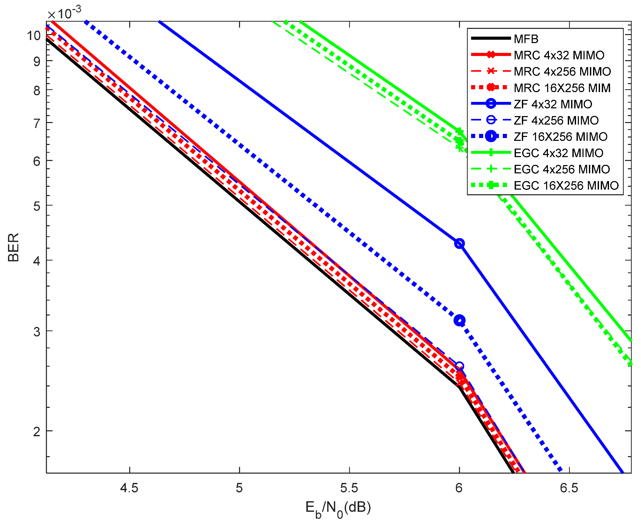
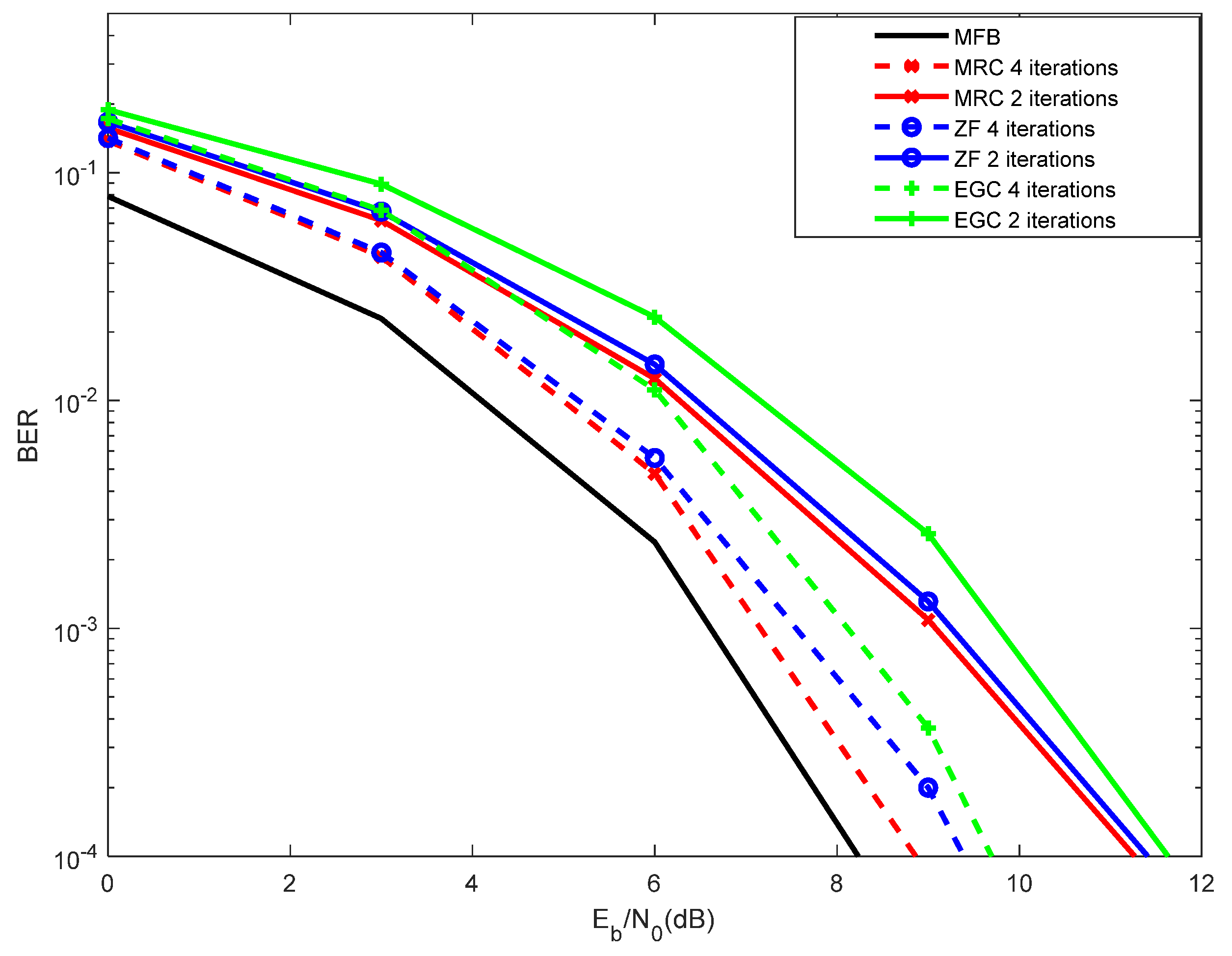
It is worth noting that an increase in the number of transmitting antennas results in an increase of the symbols rate. Moreover, increasing the number of receiving antennas results in an increase of diversity and, as a result, in performance improvement. Apart from the EGC and MRC, the Matched Filter Bound (MFB) curve is a way to measure the channel modeled by the sum of delayed and independently Rayleigh-fading rays [15].
For a massive MIMO scheme with a large number of antennas at the receiver side, this technique does not require special pilot design. Nevertheless, a problem arises for a large number of transmit antennas with uncorrelated channels, since we should have orthogonal pilots for the different transmit antennas. This means switching off all antennas, but one in a successive way.
The proposed technique is generic, and valid for all frequencies, which are suitable for mm-Wave associated with massive MIMO, due to the smaller wavelength. This allows smaller antennas and packing more antennas in a given device. The main difference when mm-Wave is employed relies on the type of channel, which, in general, has a lower number of multipath components.

3. Channel Estimation

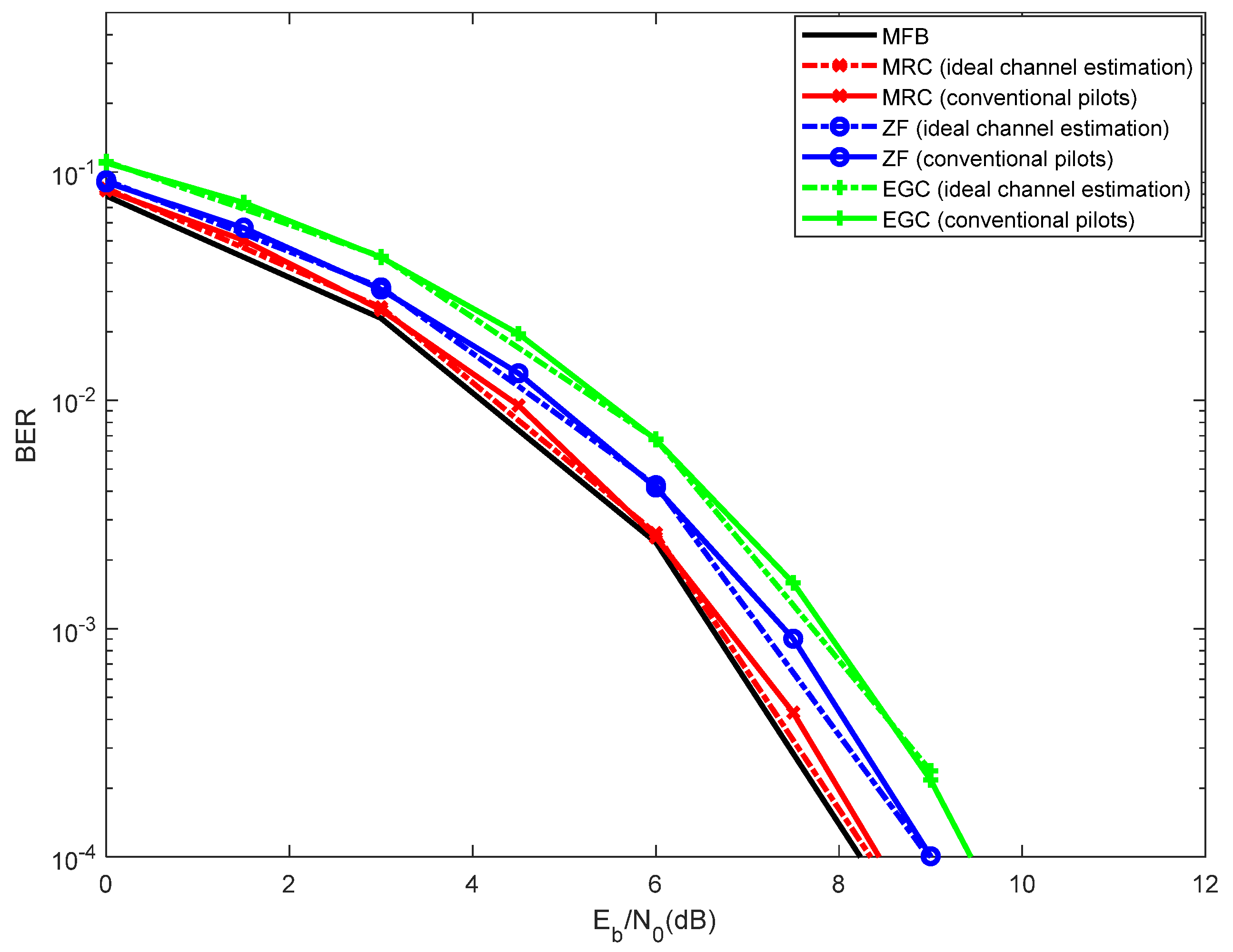
Let us first assume the use of conventional pilots, i.e., there is no data overlapping in the training block. Conventional pilots of training sequences comprise the periodic transmission of known symbols utilized by the receiver to compute the channel parameters that are required for equalization purposes. In this scenario, the channel frequency response is estimated by using [11]:
H ˜ k ( t , r ) = Y k ( r ) X k ( t ) P * 2 σ P 2 ,
where Y k ( r ) denotes the signal at the r-th received antenna ( r = 1 , 2 , , R ) , and X k ( t ) P denotes the pilot transmitted by the t-th transmit antenna ( t = 1 , 2 , , T ) . Moreover, σ P 2 denotes the power of the pilots, i.e., training sequences (P stands for the pilot). It is assumed that [21]
σ P 2 = E { | X k P | 2 } / 2 = N E { | x n P | 2 } / 2 .
If the pilots associated to different transmit antennas are orthogonal, then there is no interference between antennas when estimating the corresponding channels (e.g., by using disjoint sets of subcarriers for different antennas). In this case, we have
X k P ( m ) X k P ( q ) * = 0 m q ,
Since the channel impulse response is shorter than the cyclic prefix (which is just a fraction of the block duration), we can employ the enhanced channel estimates as [13]
H k ( t , r ) = DFT { h ˜ n ( t , r ) w n } ,
where w n = 1 if the nth time-domain sample is inside the cyclic prefix and 0 otherwise. In this case, the SNR at the channel estimates is improved by a factor T/TG, with T and TG denoting the duration of the useful part of the block and the cyclic prefix, respectively.
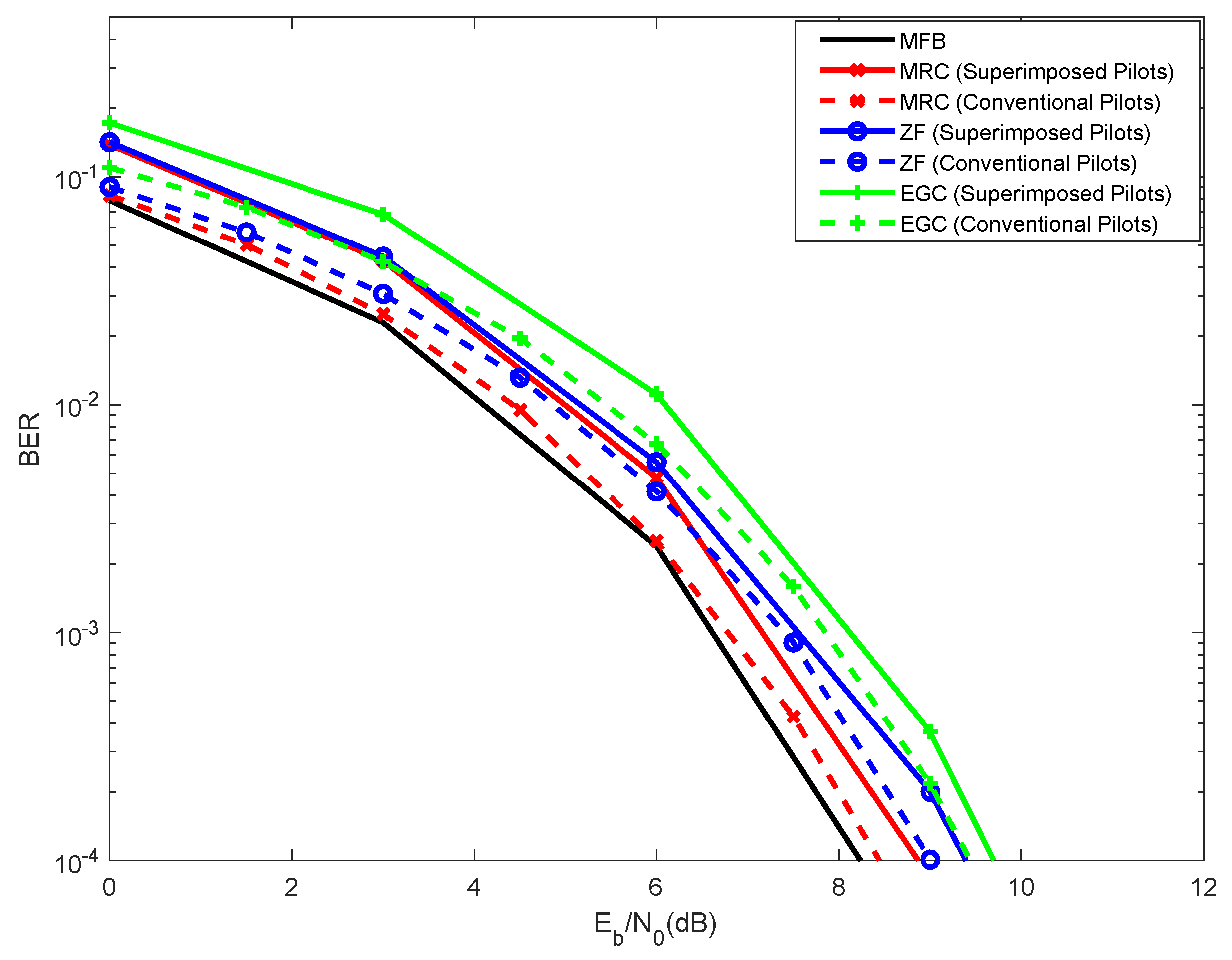
Let us consider now the use of superimposed pilots, i.e., X k 0 for the subcarriers with pilots. Superimposed pilots suppress the overheads associated with channel estimation based on conventional pilot symbols, which tends to be more demanding in the case of m-MIMO, leading to a reduction in spectral efficiency. In the following, we will assume that [21]
σ D 2 = E { | X k | 2 } / 2 = N E { | x n | 2 } / 2 ,
where σ D 2 stands for the power of the data.
Let us assume a frame with N T time-domain blocks, each with N subcarriers. If the cyclic prefix of each FFT block has N G = N T G / T samples, we will need N G equally spaced frequency-domain pilots for the channel estimation. For pilot spacings in time and frequency Δ N T and Δ N F , respectively, the total number of pilots in the frame is given by
N P F r a m e = N Δ N F · N T Δ N T ,
This means that we have a pilot multiplicity or redundancy of
N R = N P F r a m e N G = N N G Δ N F N T Δ N T ,
To avoid significant performance degradation due to channel estimation errors, the SNR associated with the channel estimation, given by SNR est N R σ P 2 / σ D 2 , should be much higher than the SNR for the data SNR data = σ D 2 / σ N 2 .
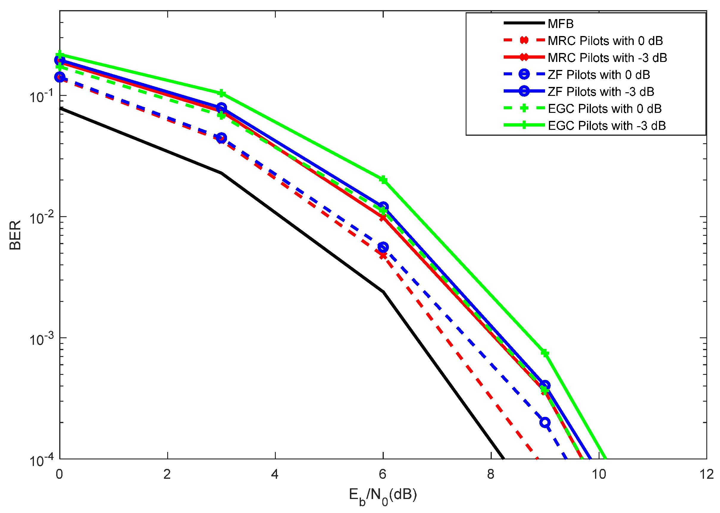
In this scenario, assuming superimposed pilots (pilots added to data), data will represent interference to the channel estimation obtained with the pilots, and the pilots will represent interference to the channel estimation obtained with the pilots, which leads to a degradation of performance. This can be mitigated by employing pilots with relatively low power and average the pilots over a large number of blocks, so as to obtain accurate channel estimates (the window size should be such that the channel should be constant within it). Since different data blocks are uncorrelated and the data symbols have usually zero mean, this approach tends to be very efficient.
Therefore, the channel is initially estimated from the pilots, and then we remove the interference (pilots) from the received signal to detect the data symbols.
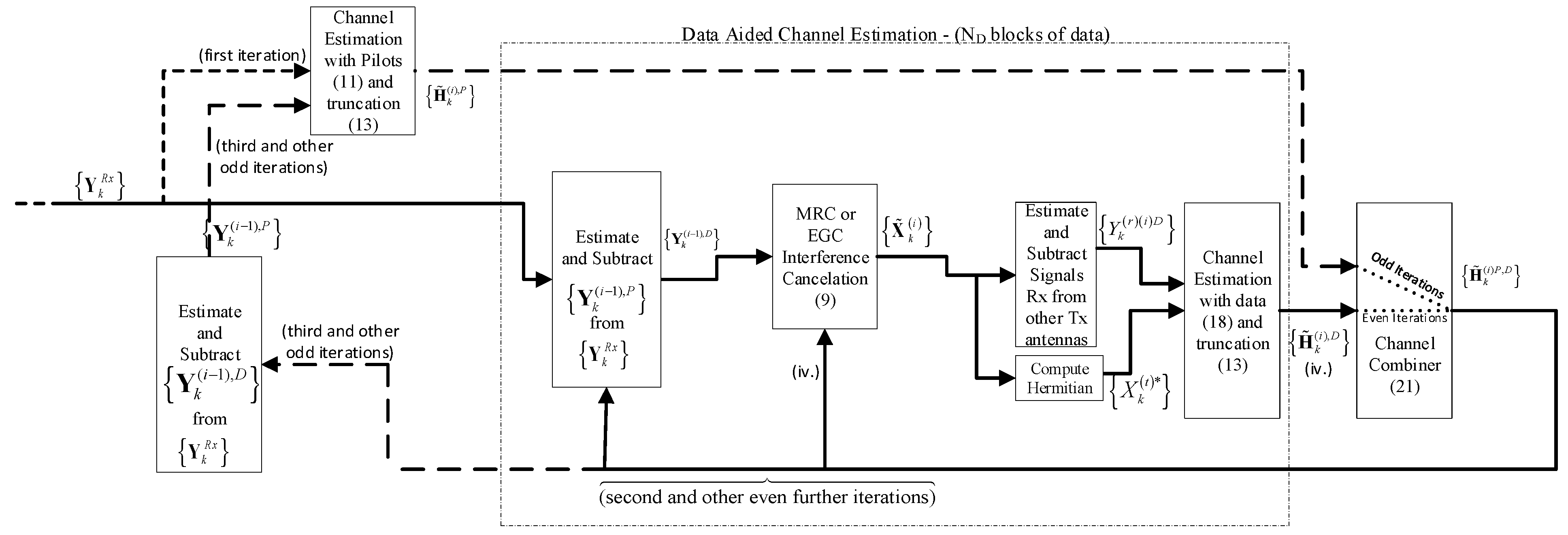
The procedure for obtaining the channel estimates follow iteratively the following three steps (see indexes in the chains of Figure 3):
  • Obtain the channel estimates from the pilots (remove the data from the received signal, estimated from the previous iteration, if not the first iteration);
  • Obtain the channel estimates from the data, after removing the pilots from the received signal (which represents interference);
  • Combine the channel estimates obtained from 1. and 2., to improve the estimate of the channel, and repeat the process.
For the first iteration (step 1), an initial channel estimation is obtained by correlating the received signal Y k ( r ) R x with the pilots, by using Equations (13) and then (16). As described above, if this is not the first iteration, then the data symbols are removed from the received blocks, as:
Y k ( r ) P = Y k ( r ) R x Y k ( r ) D = Y k ( r ) R x H k ( t , r ) X ˜ k ( t ) ,
and the channel estimation is calculated by using Equations (13) and (16).
For the second iteration (step 2), the pilots are removed from the received blocks, as
Y k ( r ) D = Y k ( r ) R x Y k ( r ) P = Y k ( r ) R x H k ( t , r ) X k ( t ) P ,
and the average values of the data symbols will be used as pilots for obtaining the channel frequency response estimate, as in [11]
H ˜ k ( i ) ( t , r ) D = Y k ( i 1 ) ( r ) D X ˜ k ( i 1 ) ( t ) * | X ˜ k ( i 1 ) ( t ) | 2 + α ,
Since using α = 0 might lead to noise enhancement effects in the channel estimates when | X k ( i ) | 2 is small, we will consider α as defined in (4). If we have moderate to high SNR then
| X k ( i ) | 2 2 σ P 2 ,
and we could use α = 0 . Note that we employ pilots with relatively low power, and we average the pilots over a large number of blocks so as to obtain accurate channel estimates.
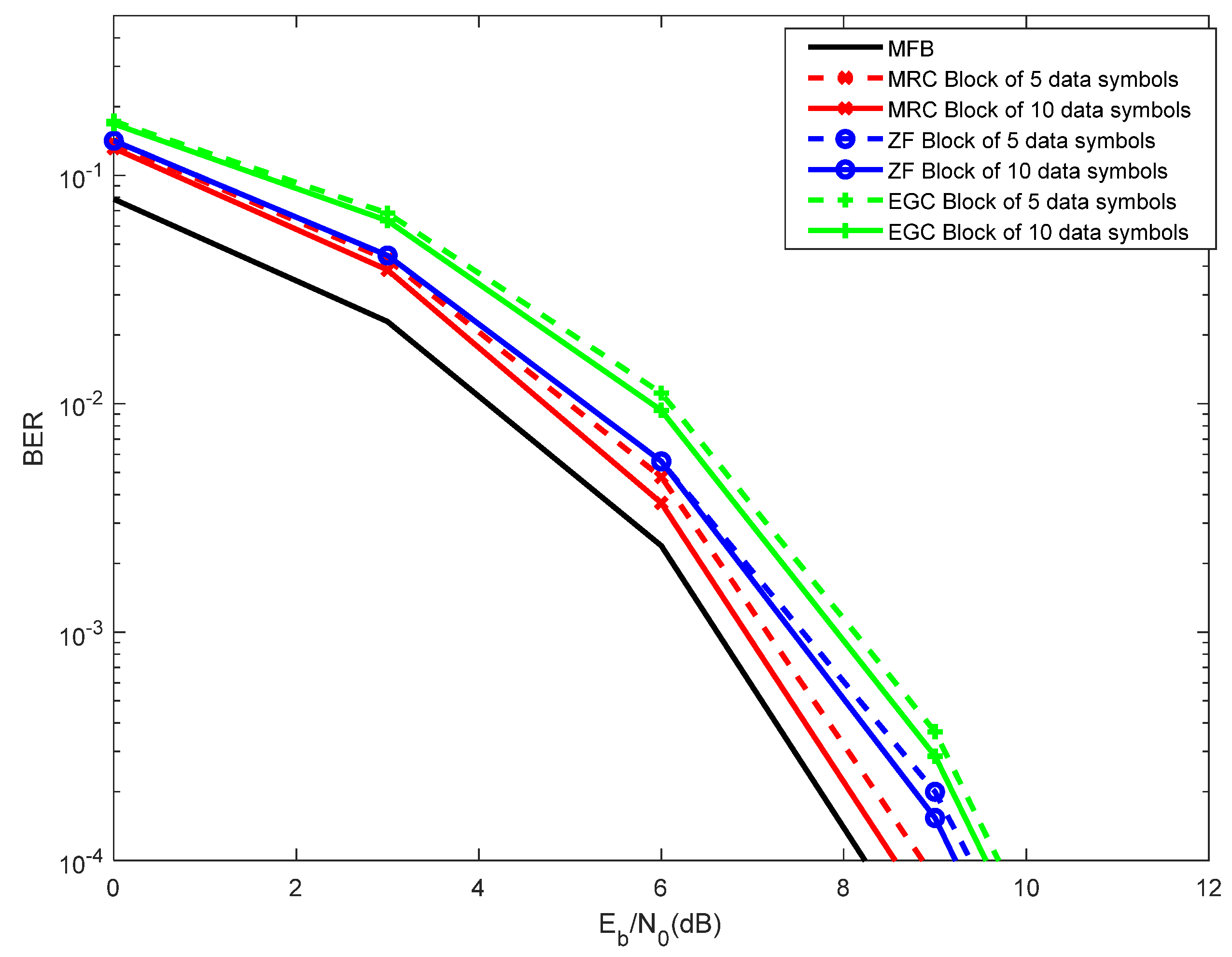
The computation of Equation (22) corresponds to an improved channel estimate obtained with the data estimated from the previous iteration is very effective because the data symbols have usually zero mean and different data blocks are uncorrelated. Naturally, there are limitations on the length of this averaging window, since the channel should be constant within it.
Finally, following step 3, the channel estimates obtained from the pilots ( H ˜ k P ) and from the data aided ( H ˜ k D ), can be combined to provide the normalized channel estimates with minimum error variance [14], as defined by
H ˜ k P , D = σ D 2 H ˜ k P + σ P 2 H ˜ k D σ D 2 + σ P 2 = H k + ε k P , D ,
where
E [ | ε k P , D | 2 ] = σ P , D 2 = σ D 2 σ P 2 σ D 2 + σ P 2 ,

4. Performance Results

This section analyses the Bit Error Rate (BER) performance obtained with m-MIMO, after the estimation of the channel parameters using superimposed pilots. SC-FDE transmission technique is considered. Monte Carlo simulations were employed to measure the performance of the proposed m-MIMO system, using QPSK modulation and with a block length of N = 256 symbols (similar results were observed for other values of N, provided that N >> 1). A Rayleigh fading channel with 16 equal power paths was assumed (invariant during the block duration). The BER is evaluated as a function of E b / N 0 , where N 0 is the one-sided power spectral density of the noise and E b is the energy of the transmitted bits.
Without loss of generality it is assumed that there is a pilot for each subcarrier of each block of the frame (and for each transmit antenna), i.e., Δ N F = Δ N T = 1 , leading to N P F r a m e = N N T and a pilot multiplicity or redundancy of N R = N P F r a m e / N G = N N T / N G . The duration of the useful part of the blocks (N symbols) is 1μs and the cyclic prefix has a duration 0.125 μs.
A transmitter with linear power amplification is assumed, as well as perfect synchronization.

4.1. Channel Estimation with Conventional Pilots

Figure 4 shows the performance obtained with ideal channel estimation versus conventional pilots. It is assumed a 4 × 32 MIMO, with 4 iterations of the interference cancellation.
Although achieving performances with conventional pilots very close to those obtained with ideal channel estimation, the conventional pilots present the disadvantage that they require reserving a part of the bandwidth for the periodic transmission of pilots or training sequence, used for data detection and equalization.
As can be seen, the MRC achieves a performance very close to the MFB. Note that the MFB consists of a performance lower bound, corresponding to a curve that quantifies the channel modeled by the sum of delayed and independently Rayleigh-fading rays. Under ideal channel conditions, the ZF is the scheme that follows the MRC in terms of performance, and the worst performance is achieved by the EGC. It is worth noting that the advantage of both MRC and EGC relies on its simplicity, as compared to the ZF. Whereas the ZF requires the computation of the inverse of the channel matrix, for each frequency component, the MRC and EGC do not. Moreover, it is known that the ZF presents noise enhancement, when utilized in post-processing mode, which is the current situation, is the reason why the MRC performs better than the ZF.
It is worth noting that the proposed technique applies to any constellation. The only difference relies on an adaptation of the interference cancellation receiver. Naturally, the sensitivity to channel estimation errors (and other impairments) increases with the constellation size. However, the main conclusions remain valid [21,22,23]. To avoid having duplication, only QPSK results are shown in this article.
As compared to OFDM, SC-FDE allows lowering the Eb/N0 values required for a certain BER, but the relative positions of curves do not change significantly.
Figure 5 shows the performance results for 4 × 32 MIMO with conventional pilots and different iterations of the interference cancellation. Even with 1 iteration, the MRC performs better than the ZF. As before, although with lower processing complexity, the EGC performs worse than the ZF. Note that, with MRC and with EGC, a certain level of interference is generated, because these receivers are not optimum. In order to mitigate such interference, the proposed receiver incorporates an interference cancellation.
As can be viewed from Figure 5, the best performances, of both MRC and EGC, are achieved with four iterations. Nevertheless, the performances obtained with four iterations are close to those obtained with three iterations. It is also observed a degradation of performance when a single iteration is assumed. Using the interference cancellation associated with the MRC and EGC, one can choose between three or four iterations, as the difference is residual. Beyond four iterations, the performance improvement was almost negligible (not shown in Figure 5). It is shown that the best performance is achieved by the MRC with 4 iterations.
Figure 6 compares the performance of the 4 × 32 MIMO against 4 × 256 MIMO and 16 × 256 MIMO. As expected, due to the higher level of receive diversity, the 4x256 MIMO performs better than the 4 × 32 MIMO. Nevertheless, it is noticeable that 16 × 256 MIMO performs worse than 4 × 256 MIMO. This occurs because the 16 × 256 MIMO comprises 16 parallel flows of symbols, while 4 × 256 MIMO comprises only 4 parallel flows of data, and therefore 16 × 256 MIMO corresponds to more data being transmitted, but also to more interference. This is valid for the MRC, EGC and ZF. It can be viewed that the results obtained with the MRC, for the 4 × 256 MIMO, are almost superimposed with the MFB curve.

4.2. Channel Estimation with Superimposed Pilots

For the purpose of channel estimation, this section considers superimposed or implicit pilots, i.e., pilots added to the data. The advantage of this approach relies on the fact that there is no need to reserve a certain bandwidth to send pilots or training sequences. Nevertheless, using superimposed pilots, data represents interference to the channel estimate obtained with the pilots, and the pilots represent interference to the channel estimate obtained with the data, which leads to a degradation of performance. This can be mitigated by employing pilots with relatively low power and average the pilots over a large number of blocks, so as to obtain accurate channel estimates (the window size should be such that the channel should be constant within it). We propose the receiver shown in Figure 3, which consists of the following phases:
  • Perform an initial channel estimation using the pilots (added to the data).
  • Remove the pilots (that represent interference), detect the data, and perform an initial channel estimate using the data.
  • Combine the channel estimate obtained from step 1. with that of step 2.
  • Repeat steps 1 to 3 iteratively, with the new improved channel estimates, and removing the estimated data from the pilots of step 1.
Figure 7 considers the performance results obtained with superimposed pilots compared with those obtained with conventional pilots. The superimposed pilots consider pilots power of 0 dB (pilots with the same power as the data), with a block length of five blocks of data symbols used to estimate the channel, and four iterations of the iterative channel estimator. As can be viewed, although the performances obtained with conventional pilots are slightly better than those obtained with superimposed pilots, the differences are residual. Nevertheless, superimposed pilots present the advantage of not having to reserve a certain bandwidth for the purpose of estimating the channel. Regardless of whether superimposed or conventional pilots are employed, the best overall performance is obtained with the MRC, being followed by the ZF and, finally, by the EGC. Once again, the ZF performs worse than the MRC because the former presents noise enhancement.
Figure 8 presents the performance results obtained superimposed pilots, with two versus four iterations of the channel estimator, with pilots power of 0 dB.
As previously described, two iterations simply consider one initial estimation from the pilots and another estimation from the data (after removing the pilots). These two estimates are combined, and the result is used to detect the data. In the case of four iterations of the channel estimator, this process is repeated, i.e., a third iteration considers the channel estimate from the pilots (after removing the data) and a fourth iteration, where the channel estimate is obtained from the data (after removal of the pilots). In this scenario, the estimates obtained in the third and fourth iterations are combined, and the result is used to perform data detection. The interference between pilots and data is mitigated by employing pilots with relatively low power and average the pilots over a large number of blocks, so as to obtain accurate channel estimates (the window size should be such that the channel should be constant within it). In this case, we have assumed a block of five symbols.
As expected, the performance results with four iterations are always better than those obtained with two iterations. This is valid for both MRC, ZF and EGC. As before, the best overall performance is obtained with the MRC (with 4 iterations). It is worth noting that, beyond 4 iterations, the performance improvement is residual (not shown). Therefore, the proposed receivers and channel estimators should employ 4 iterations to achieve good performance.
Figure 9 considers the performance results with superimposed pilots, assuming a pilots power of 0 dB versus −3 dB, using a block length of 5 data symbols. It is worth noting that 0 dB corresponds to using the same power for the pilots and for the data, whereas −3 dB corresponds to using half of the power for the pilots, as compared to the data power. Regardless the receiver employed, the best overall performance is always achieved with a pilots power of 0 dB. It is worth noting that simulations with a pilots power of 3 dB were implemented (not shown in this article), but the best performance was also 0 dB. By using −3 dB of pilots power, small degradation of performance can be observed, being valid for both MRC, ZF and EGC.
Figure 10 shows the performance results for the 4 × 32 MIMO with Superimposed Pilots, with a block length of five versus 10 data symbols. The performances obtained with 10 data symbols are always slightly better than those obtained with five data symbols. This is valid for both MRC, ZF and EGC. Nevertheless, this is obtained at the cost of much higher processing power, as 10 data blocks requires processing the double of the data than five data blocks. It is worth noting that degradation of performance is experienced when less than five data blocks are employed (simulations carried out, but not shown in this article). Therefore, considering the differences of performance, one can conclude that five data blocks is a good tradeoff between performance and processing complexity. As before, the best overall performance is obtained with the MRC, being followed by the ZF and, finally, by the EGC.

5. Conclusions

This article proposes and studies an efficient and low complex receiver that jointly performs channel estimation based on superimposed pilots, and data detection, optimized for massive MIMO. 5G Communications will support mm-Wave, which will enable much higher throughputs and facilitate the employment of Massive MIMO.
The use of superimposed pilots avoids the overheads associated with channel estimation based on conventional pilot symbols, which tends to be more demanding in the case of m-MIMO, and therefore, this technique achieves an improvement of spectral efficiency.
The proposed receiver uses two low complex algorithms: the MRC and the EGC. These algorithms are compared with the ZF. The advantage of the MRC and EGC relies on the fact that the ZF requires the computation of the pseudo-inverse of the channel matrix for each frequency component, processing not required with MRC/EGC, keeping the complexity requirements at a low level.
It was viewed that the MRC algorithm implemented in the proposed iterative receiver, which performs channel estimation using superimposed pilots and data detection for m-MIMO, achieves a performance very close to the MFB, just after few iterations. It was also viewed that the MRC achieves better performance than the ZF, even with a reduction of complexity, which occurs since ZF introduces noise enhancement.

Author Contributions

All authors contributed equally to the article. All authors have read and agreed to the published version of the manuscript.

Funding

This work is funded by FCT/MCTES through national funds and when applicable co-funded EU funds under the project UIDB/EEA/50008/2020.

Acknowledgments

We acknowledge the support of FCT/MCTES, as described above in funding.

Conflicts of Interest

The authors declare no conflict of interest.

References

  1. Rusek, F.; Persson, D.; Lau, B.K.; Larsson, E.G.; Marzetta, T.L.; Edfors, O.; Tufvesson, F. Scaling up MIMO: Opportunities and challenges with very large arrays. IEEE Signal Process. Mag. 2013, 30, 40–60. [Google Scholar] [CrossRef] [Green Version]
  2. Hassan, N.; Fernando, X. Massive MIMO Wireless Networks: An Overview. Electronics 2017, 6, 63. [Google Scholar] [CrossRef] [Green Version]
  3. Rappaport, T.S.; Sun, S.; Mayzus, R.; Zhao, H.; Azar, Y.; Wang, K.; Wong, G.N.; Schulz, J.K.; Samimi, M.; Gutierrez, F. Millimeter Wave Mobile Communications for 5G Cellular: It Will Work! IEEE Access 2013, 1, 335–349. [Google Scholar] [CrossRef]
  4. IEEE 802.11 Task Group AD, PHY/MAC Complete Proposal Specification. Available online: http://www.ieee802.org/11/Reports/tgad_update.htm (accessed on 12 March 2020).
  5. Nie, S.; MacCartney, G.; Sun, S.; Rappaport, T. 28 GHz and 73 GHz Signal Outage Study for Millimeter Wave Cellular and Backhaul Communications. In Proceedings of the 2014 IEEE ICC, Sydney, Australia, 10–14 June 2014. [Google Scholar]
  6. Han, S.; Lin, C.; Xu, Z.; Rowell, C. Large-Scale Antenna Systems with Hybrid Analog and Digital Beamforming for Millimeter Wave 5G. IEEE Commun. Mag. 2015, 53, 186–193. [Google Scholar] [CrossRef]
  7. Larsson, E.; Edfors, O.; Tufvesson, F.; Marzetta, T. Massive MIMO for next generation wireless systems. IEEE Commun. Mag. 2014, 52, 186–195. [Google Scholar] [CrossRef] [Green Version]
  8. Akpakwu, G.; Silva, B.J.; Hancke, G.P.; Abu-Mahfouz, A.M. A Survey on 5G Networks for the Internet of Things: Communication Technologies and Challenges. IEEE Access 2017, 6, 3619–3647. [Google Scholar] [CrossRef]
  9. Sachs, J.; Wikstrom, G.; Dudda, T.; Baldemair, R.; Kittichokechai, K. 5G Radio Network Design for Ultra-Reliable Low-Latency Communication. IEEE Network 2018, 32, 24–31. [Google Scholar] [CrossRef]
  10. Da Silva, M.M. Cable and Wireless Networks: Theory & Practice, 1st ed.; CRC Press: Boca Raton, FL, USA, 2016; ISBN 9781498746816. [Google Scholar]
  11. Da Silva, M.M.; Dinis, R. Iterative Frequency-Domain Detection and Channel Estimation for Space-Time Block Codes European Transactions on Telecommunications; John Wiley & Sons, Ltd.: Hoboken, NJ, USA, 2011; Volume 22, pp. 339–351. [Google Scholar]
  12. Li, Y.; Han, K.; Dong, C. A Multi-Band Low-Noise Transmitter with Digital Carrier Leakage Suppression and Linearity Enhancement. IEEE Trans. Circuits Syst. I 2013, 60, 1209–1219. [Google Scholar] [CrossRef]
  13. Gusmão, A.; Dinis, R.; Conceição, J.; Esteves, N. Comparison of Two Modulation Choices for Broadband Wireless Communications. In Proceedings of the VTC2000-Spring. 2000 IEEE 51st Vehicular Technology Conference, Tokyo, Japan, 15–18 May 2000. [Google Scholar]
  14. Da Silva, M.M.; Dinis, R.; Guerreiro, J. Implicit Pilots for an Efficient Channel Estimation in Simplified Massive MIMO Schemes with Precoding. Int. J. Antennas Propag. 2019, 2019. [Google Scholar] [CrossRef]
  15. Da Silva, M.M.; Dinis, R. A Simplified Massive MIMO Implemented with Pre or Post-Processing. Phys. Commun. 2017, 1, 1–12. [Google Scholar] [CrossRef]
  16. Dinis, R.; Lam, C.; Falconer, D. Joint frequency-domain equalization and channel estimation using superimposed pilots. In Proceedings of the IEEE Wireless Communications and Networking Conference, Las Vegas, NV, USA, 31 March–3 April 2008. [Google Scholar]
  17. Li, H.; Jin, R.; Wei, S.; Cheng, W.; Kong, W.; Liu, P. Distributed Structured Compressive Sensing-Based Time-Frequency Joint Channel Estimation for Massive MIMO-OFDM Systems. Mob. Inf. Syst. 2019. [Google Scholar] [CrossRef]
  18. Riadi, A.; Boulouird, M.; Hassan, M. ZF/MMSE and OSIC Detectors for UpLink OFDM Massive MIMO systems. In Proceedings of the 2019 IEEE Jordan International Joint Conference on Electrical Engineering and Information Technology (JEEIT), Amman, Jordan, 9–11 April 2019. [Google Scholar]
  19. Benvenuto, N.; Dinis, R.; Falconer, D.; Tomasin, S. Single Carrier Modulation with Non-Linear Frequency Domain Equalization: An Idea Whose Time Has Come—Again. IEEE Proc. 2010, 98, 69–96. [Google Scholar] [CrossRef] [Green Version]
  20. Da Silva, M.M.; Correia, A.; Dinis, R.; Souto, N.; Silva, J. Transmission Techniques for Emergent Multicast and Broadcast Systems, 1st ed.; CRC Press Auerbach Publications: New York, NY, USA, 2010; ISBN 9781439815939. [Google Scholar]
  21. Da Silva, M.M.; Monteiro, F.A. MIMO Processing for 4G and Beyond: Fundamentals and Evolution; CRC Press Auerbach Publications: Boca Raton, FL, USA, 2014; ISBN 9781466598072. [Google Scholar]
  22. Dinis, R.; Montezuma, P.; Souto, N.; Silva, J. Iterative Frequency-Domain Equalization for General Constellations. In Proceedings of the 2010 IEEE Sarnoff Symposium, Princeton, NJ, USA, 12–14 April 2010. [Google Scholar]
  23. Dinis, R.; Silva, J.C.; Souto, N.; Montezuma, P. On the Design of Turbo Equalizers for SC-FDE Schemes with Different Error Protections. In Proceedings of the VTC’2010 Fall, Ottawa, ON, Canada, 6–9 September 2010. [Google Scholar]
Figure 1. Block diagram of massive Multiple Input–Multiple Output (m-MIMO) with Single-Carrier with Frequency-Domain Equalization (SC-FDE) signals.
Telecom 01 00002 g001
Figure 2. Block diagram of m-MIMO chain with receiver and interference cancellation.
Telecom 01 00002 g002
Figure 3. Block diagram of m-MIMO receiver.
Telecom 01 00002 g003
Figure 4. Bit Error Rate (BER) results for 4 × 32 MIMO with conventional pilots versus ideal channel estimation.
Telecom 01 00002 g004
Figure 5. BER results for 4 × 32 MIMO with conventional pilots and different iteration of interference cancellation.
Telecom 01 00002 g005
Figure 6. BER results for 4 × 32 MIMO versus 4 × 256 MIMO and 16 × 256, with conventional pilots.
Telecom 01 00002 g006
Figure 7. BER results for 4 × 32 MIMO with conventional pilots versus superimposed pilots.
Telecom 01 00002 g007
Figure 8. BER results for 4 × 32 MIMO with superimposed pilots, with two versus four iterations of the iterative channel estimator.
Telecom 01 00002 g008
Figure 9. BER results for 4 × 32 MIMO with superimposed pilots, with pilot power of 0 dB versus −3 dB.
Telecom 01 00002 g009
Figure 10. BER results for 4 × 32 MIMO with superimposed pilots, with a block of 5 versus 10 data symbols.
Telecom 01 00002 g010

