Article

Optimizing a Hydrogen and Methane Blending System Through Design and Simulation

by
Ştefan Ionuţ Spiridon
,
Bogdan Florian Monea
and
Eusebiu Ilarian Ionete
*
National Research and Development Institute for Cryogenic and Isotopic Technologies—ICSI, 240050 Ramnicu Valcea, Romania
*
Author to whom correspondence should be addressed.
Fuels 2025, 6(2), 28; https://doi.org/10.3390/fuels6020028
Submission received: 12 December 2024 / Revised: 13 February 2025 / Accepted: 16 March 2025 / Published: 10 April 2025

Abstract

:
Hydrogen–methane gas mixtures are increasingly recognized as a viable path toward achieving carbon neutrality, leveraging existing natural gas infrastructure while reducing greenhouse gas emissions. This study investigates a novel static mixing device designed for blending hydrogen and methane, employing both experimental tests and three-dimensional computational fluid dynamics (CFD) simulations. Hydrogen was introduced into a methane flow via direct injection, with experimental mixtures ranging from 5% to 18% hydrogen. The mixture quality was assessed using a specialized gas chromatograph, and the results were compared against simulated data to evaluate the mixer’s performance and the model’s accuracy. The system demonstrated effective blending, maintaining uniform hydrogen concentrations across the outlet with minimal variations. Experimental and simulated results showed strong agreement, with an average accuracy error below 2%, validating the reliability of the CFD model. Smaller nozzles (0.4 mm) achieved greater mixing uniformity, while larger nozzles (0.6 mm) facilitated higher hydrogen throughput, indicating trade-offs between mixing precision and flow capacity. The mixing device proved compatible with existing pipeline infrastructure, offering a scalable solution for hydrogen integration into natural gas networks. These findings underscore the mixer’s potential as a practical component in advancing the hydrogen economy and achieving sustainable energy transitions.

1. Introduction

The global energy landscape is undergoing a transformative shift toward cleaner, more sustainable alternatives to fossil fuels. Hydrogen, as a versatile and zero-emission energy carrier, plays a critical role in this transition. With its ability to be generated from renewable sources and its compatibility with various energy applications, hydrogen is a key enabler for decarbonizing industries, transportation, and energy systems [1]. Among its many applications, blending hydrogen into natural gas networks has gained substantial interest as a pathway to reduce carbon emissions while leveraging existing infrastructure [2].
Hydrogen-enriched compressed natural gas (HCNG) is increasingly being recognized as a viable solution for reducing greenhouse gas emissions and improving energy efficiency in various applications. Studies have demonstrated that hydrogen’s high diffusivity and low ignition energy can enhance the combustion characteristics of methane, resulting in higher thermal efficiency and lower emissions of pollutants such as carbon dioxide (CO2), nitrogen oxides (NOx), and particulate matter [1,2,3,4]. Furthermore, HCNG has shown potential in improving engine performance in internal combustion applications by enabling faster combustion and reducing knocking tendencies [5,6,7,8].
Despite these advantages, the adoption of hydrogen–methane mixtures faces several technical and operational challenges. The significant differences in physical and chemical properties between hydrogen and methane—such as density, viscosity, and diffusivity—affect their blending dynamics and pipeline transport. Hydrogen’s low density and high diffusivity can lead to stratification and uneven concentration profiles during transport, posing risks of localized embrittlement and uneven combustion [9,10,11,12]. Additionally, the energy density of hydrogen is lower than methane, necessitating careful adjustments in flow rates and pressures to achieve comparable calorific values [13,14].
Blending hydrogen with methane represents a key step in the global transition toward clean energy. Integrating hydrogen into existing natural gas networks offers an economical and practical pathway to decarbonize energy systems while utilizing established infrastructure. However, significant challenges arise from the physical and chemical differences between hydrogen and methane, including their density, diffusivity, and energy content, which affect blending, transport, and combustion characteristics [1,2]. Addressing these challenges requires the development and implementation of advanced mixing technologies.
Static mixers, also known as motionless mixers, have gained prominence as efficient devices for blending hydrogen with methane. These systems, devoid of moving parts, utilize internal geometries to generate turbulence and promote homogenization. Their simplicity, reliability, and low maintenance requirements make them ideal for both industrial and laboratory applications. Several designs of static mixers (Table 1) have been adapted for hydrogen–methane blending. Tab or plate mixers are among the most common types, offering low energy consumption and easy maintenance. However, these mixers may suffer from limitations such as fouling and restricted mixing efficiency, particularly in complex flow conditions. Helical mixers, which enhance mixing through twisted internal elements, are particularly suitable for smaller pipelines and offer improved heat transfer. Nevertheless, they can lead to significant pressure drops and higher operational energy costs. For high-pressure applications, nozzle injection systems and cartridge mixers have been employed, offering rapid mixing and modularity, though they may incur higher maintenance costs and energy demands [10,15].
Recent advancements in static mixing technologies have focused on addressing the unique challenges posed by hydrogen’s properties. Computational fluid dynamics (CFD) has become an indispensable tool in optimizing mixer geometries and configurations. By simulating flow dynamics, turbulence, and concentration profiles, researchers have been able to design mixers that achieve uniform blending with minimal pressure losses. For example, studies have demonstrated the effectiveness of helical static mixers in achieving high-quality mixing in gas–liquid systems, even under laminar flow conditions [12]. Moreover, real-time monitoring technologies, such as gas chromatographs and optical sensors, have been integrated into mixing systems to measure hydrogen concentrations and calorific values accurately. These advancements ensure operational safety, optimize energy delivery, and enable adaptable mixing solutions for varying hydrogen–methane ratios [4].
The importance of developing advanced mixing systems for hydrogen–methane blending cannot be overstated. Uniform blending is essential to prevent issues such as stratification, localized combustion irregularities, and material embrittlement in pipelines. Furthermore, achieving consistent hydrogen distribution enhances the overall efficiency of combustion systems and reduces the risks associated with hydrogen’s high reactivity. The modular and scalable nature of modern static mixers also allows for their deployment across diverse applications, from small-scale laboratory setups to large industrial installations. These systems play a vital role in enabling the integration of hydrogen into natural gas networks, contributing to the decarbonization of the energy sector while maintaining the reliability of existing infrastructure [5,9].
This study aims to address the challenges of hydrogen–methane mixing by designing, simulating, and experimentally validating a novel static mixing device tailored for hydrogen-enriched natural gas streams. The primary objectives of this research are to develop a geometrically optimized static mixer capable of achieving homogeneous blending of hydrogen and methane, to minimize pressure drops and energy losses associated with the mixing process, and to integrate real-time monitoring and control systems to ensure precise adjustment of hydrogen concentrations based on operational requirements. The proposed approach combines experimental testing with CFD simulations to evaluate and refine the mixing system. This integration allows for the identification of key parameters affecting mixing efficiency, such as nozzle geometry, flow turbulence, and mixing length.
The innovation of this work lies in its comprehensive approach to addressing the challenges of hydrogen–methane blending through the development of a novel static mixing device and real-time monitoring system. The proposed mixer features a robust stainless steel, pipe-in-pipe design with patented internal elements that enhance turbulence and ensure efficient blending without requiring moving parts or electrical components, making it maintenance-free and reliable. Additionally, the integration of an advanced gas chromatograph analyzer utilizing opto-sonic technology enables precise, real-time measurement of hydrogen concentration and calorific values, ensuring safe and consistent operation. The modular design of the system allows for scalability and flexibility, accommodating various blending ratios through adjustable nozzle diameters and injection configurations. By combining these innovations with CFD simulations and experimental validation, this research offers a practical and scalable solution for integrating hydrogen into existing natural gas networks, providing a significant step forward in decarbonizing energy systems and advancing the adoption of hydrogen as a clean energy carrier.

2. Materials and Methods

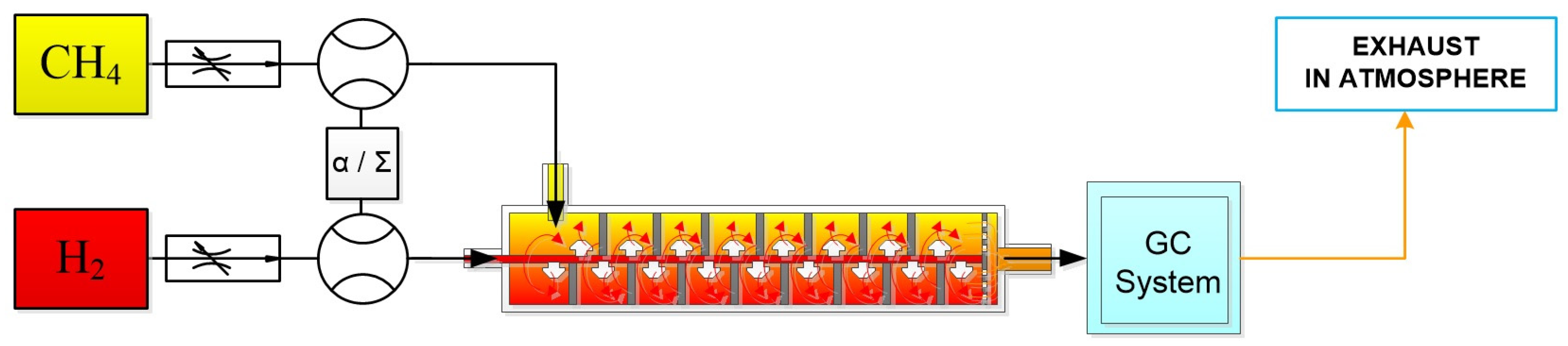
2.1. Experimental Setup

The experimental system (Figure 1) was designed to investigate the formation and behavior of CH4 + H2 mixtures in a controlled mixing chamber. The central component of the system is the pipe-in-pipe static mixer, constructed from 306 L stainless steel for durability and resistance to corrosion. The mixer incorporates patented internal elements from the ICSI Rm. Vâlcea portfolio [33], designed to enhance turbulence and homogenization without requiring moving parts or external electrical power.
Adjacent to the mixer, a gas chromatograph (700XA type, Emerson, Saint Louis, MO, USA) is installed to perform real-time analysis of the hydrogen-enriched methane gas mixture. This advanced analyzer determines the molar composition of the mixture and calculates its calorific value using an innovative opto-sonic concept. The system measures the speed of light and sound through the gas stream, enabling precise determination of mixture properties, even at low hydrogen concentrations. An accuracy/measurement error of ±0.20% in uncontrolled environments with temperature ranges from −20 °C to 60 °C is reported for the gas chromatograph. The analyzer is configured to operate in an outdoor environment, making it suitable for field applications.

2.1.1. Mixing Flow and Design

Hydrogen gas is injected directly into the methane gas stream within the mixing chamber. The hydrogen injection system is equipped with nozzles distributed along an injection pipe, oriented alternately up and down, and positioned diametrically opposite. Circular screens are strategically placed behind each nozzle to redirect the flow and promote localized mixing. The screens are designed with a cut at the top, aligned with the nozzle, to allow the mixed gas stream to pass through while simultaneously inducing turbulence for homogenization.
The injection process occurs progressively, with smaller nozzles located upstream and larger ones downstream. This arrangement ensures a gradual increase in hydrogen concentration while compensating for pressure drops along the flow path. The diameters of the nozzles used in the experiments were 0.4 mm and 0.6 mm, allowing for flexibility in achieving different mixture ratios. The modularity of the system enables the replacement of nozzles to accommodate various operational requirements.
The output flow rate of the system, which varies based on the inlet pressures of the gases being mixed, can reach up to 25 Nm3/h. The hydrogen concentration was limited to 5–18%, primarily due to safety concerns. Beyond these values, embrittlement phenomena may occur, posing structural risks. Additionally, the system was specifically designed to mitigate these effects throughout the mixing process, ensuring safe and reliable operation.

2.1.2. Gas Chromatography and Measurement

The gas chromatograph installed in proximity to the mixing chamber provides continuous online analysis of the gas mixture; it was calibrated using a pressurized cylinder containing a certified gas mixture, ensuring accurate and reliable measurements. It can quantify a wide range of compounds present in the natural gas stream with high precision, supporting various hydrogen-to-methane ratios. In addition to molar composition, the calorific properties of the mixtures are calculated to evaluate energy content. This dual capability is critical for optimizing the mixing process and ensuring compatibility with downstream applications.

2.1.3. Operational Conditions

The system was configured to test a range of hydrogen concentrations by varying the injection nozzle diameters and flow rates. While the primary experiments focused on hydrogen and methane, the system design supports the use of other gases with similar densities. However, it is noted that the resulting data may vary due to differences in gas properties.

2.1.4. Experimental Validation

The effectiveness of the mixing system was evaluated by comparing the gas composition obtained from the gas chromatograph with the expected theoretical distributions. The progressive injection method and internal mixer geometry were assessed for their ability to achieve uniform blending with minimal stratification. Additionally, pressure drops across the system were measured to ensure compatibility with industrial applications.
This robust and adaptable experimental setup provides a reliable platform for exploring the dynamics of hydrogen–methane mixtures, supporting the development of efficient mixing technologies for energy applications.

2.2. Computational Model

2.2.1. Geometry

The geometry of the mixing device (Figure 2) was created based on a pipe-in-pipe static mixer design, incorporating internal elements optimized for efficient blending of CH4 and H2. The 3D model of the fluid domain was developed using CATIA (Dassault Systèmes, Paris, France) and subsequently imported into ANSYS FLUENT for numerical simulations. The mixer included a series of nozzles (diameter: 0.4 mm for this study) arranged along the mixing zone, with screens and flow deflectors enhancing turbulence and homogenization.
The discretization of the geometry into a computational mesh was a critical step in transitioning from a physical to a numerical model. The mesh for the 0.4 mm nozzle geometry included 2,119,598 polyhedral cells, 10,950,173 faces, and 7,458,087 nodes. Quality metrics were evaluated, yielding a minimum orthogonal quality of 0.15 and a maximum aspect ratio of 52.35, ensuring a balance between computational efficiency and numerical accuracy.

2.2.2. Simulation Parameters

Simulations were conducted using ANSYS FLUENT 2022 R2, leveraging its robust suite of algorithms for fluid flow analysis. The computational setup included the following:
  • Solver type: pressure-based, steady-state solver;
  • Turbulence model: SST k-ω, combining the strengths of k-ω (boundary layer flow description) for near-wall flow and k-ε (fluid free flow description) for free-stream regions [34]; This model was chosen because it effectively combines the advantages of the k-ε model, which performs well in free-stream regions, and the k-ω model, which provides higher accuracy near boundary layers close to the wall. Using only the k-ε model would have resulted in less accurate results.
  • Species transport: modeled the convection–diffusion dynamics of CH4 and H2 using the species transport equation [35]
ρ Y i t + · ρ Y i U = · ρ D i Y i + R i
where ρ is the fluid density, Yi is the mass fraction of species i, U is the velocity vector, Di is the diffusion coefficient, and Ri is the rate of production;
  • Boundary conditions: For the boundary conditions, we applied (i) pressure conditions at the inlet and outlet, (ii) stationary walls with a no-slip condition, (iii) standard roughness, and (iv) zero heat flux (adiabatic conditions) in order to replicate realistic pipeline conditions and ensure the accuracy of the computational model. Inlet pressures for H2 ranged from 200 to 300 kPa, with CH4 pressures adjusted to achieve H2 mass fractions at the outlet between 5% and 18%. The set reference pressure and temperature were 101,325 Pa and 300 K, respectively. Mixture density: the compressible ideal gas, viscosity: 1.72 × 10⁻⁵ kg/m·s. Wall boundary conditions were stationary walls, no slip condition, standard roughness, and zero heat flux (adiabatic condition). The influence of gravitational forces was not considered.

2.2.3. Solver Configuration

Simulations employed the “Coupled” algorithm [36] for pressure–velocity coupling, with second-order discretization schemes for momentum, turbulence, and species transport equations. The convergence criteria were set to achieve residuals below 10−5, with a minimum of 1000 iterations required for solution stabilization.

3. Results and Discussions

The results of the numerical simulations provided significant insights into the performance of the static mixer under various operating conditions. We focused our study on evaluating the mixing quality, hydrogen concentration distribution, pressure profiles, and the impact of nozzle geometry and operating conditions on the system’s efficiency.

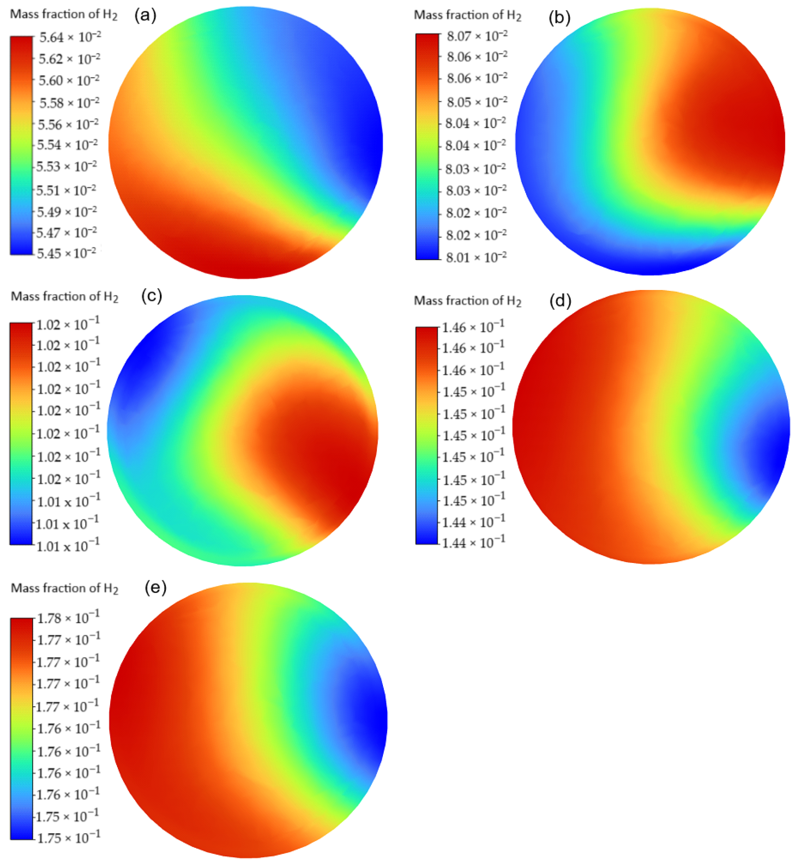
3.1. Mixing Performance

To achieve a homogeneous CH4-H2 mixture at the outlet of the static mixer was the primary aim of this work. A series of simulations were performed to study the behavior of the H2-CH4 mixture for different inlet conditions and nozzle configurations. Table 2 summarizes the results for the 0.4 mm nozzle geometry, covering H2 mass fractions between 5.45% and 17.8%. The data show a clear correlation between the inlet pressures and the achieved H2 mass fractions. Higher H2 inlet pressures facilitated increased mass fractions at the outlet, with a consistent and predictable trend. The system maintained its mixing efficiency across all cases, with negligible deviations from the targeted mass fractions.
Effective mixing was demonstrated by the results, with variations in the H2 mass fraction at the outlet consistently below 0.3% across the cases simulated. This indicates that the internal geometry of the mixer, including the progressive injection mechanism and deflectors, successfully generated sufficient turbulence to ensure uniform distribution. Figure 3 presents mass fraction contours for representative cases (A1–A5).
These contours reveal how H2 concentration evolved as it diffused into the CH4 stream, with gradual homogenization achieved downstream. The progressive injection of H2 through the nozzles and the internal flow deflectors contributed to turbulence generation and rapid mixing.
The turbulence induced by the mixer design was sufficient to overcome challenges posed by the low density and high diffusivity of H2, ensuring consistent mixing without stratification.
Additionally, pressure profiles across the mixer were analyzed to understand the energy losses associated with the mixing process. Figure 4 illustrates the pressure distribution for case A2, where CH4 and H2 inlet pressures were 215 kPa and 250 kPa, respectively, with an outlet pressure of 200 kPa.
The pressure gradient within the mixer was smooth, indicating minimal resistance introduced by the geometry. The low-pressure drop across the system suggests that the mixer design is suitable for integration into existing pipeline networks without requiring significant energy compensation. The progressive injection mechanism helped distribute the pressure drop evenly, avoiding localized high-pressure zones that could compromise system performance.

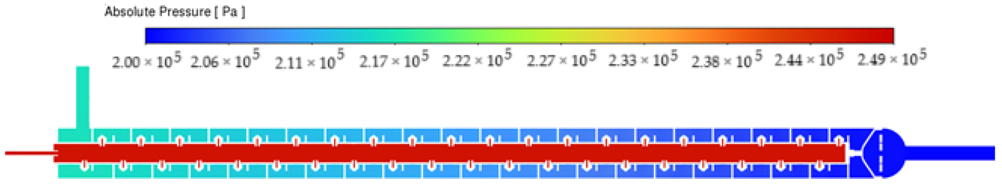
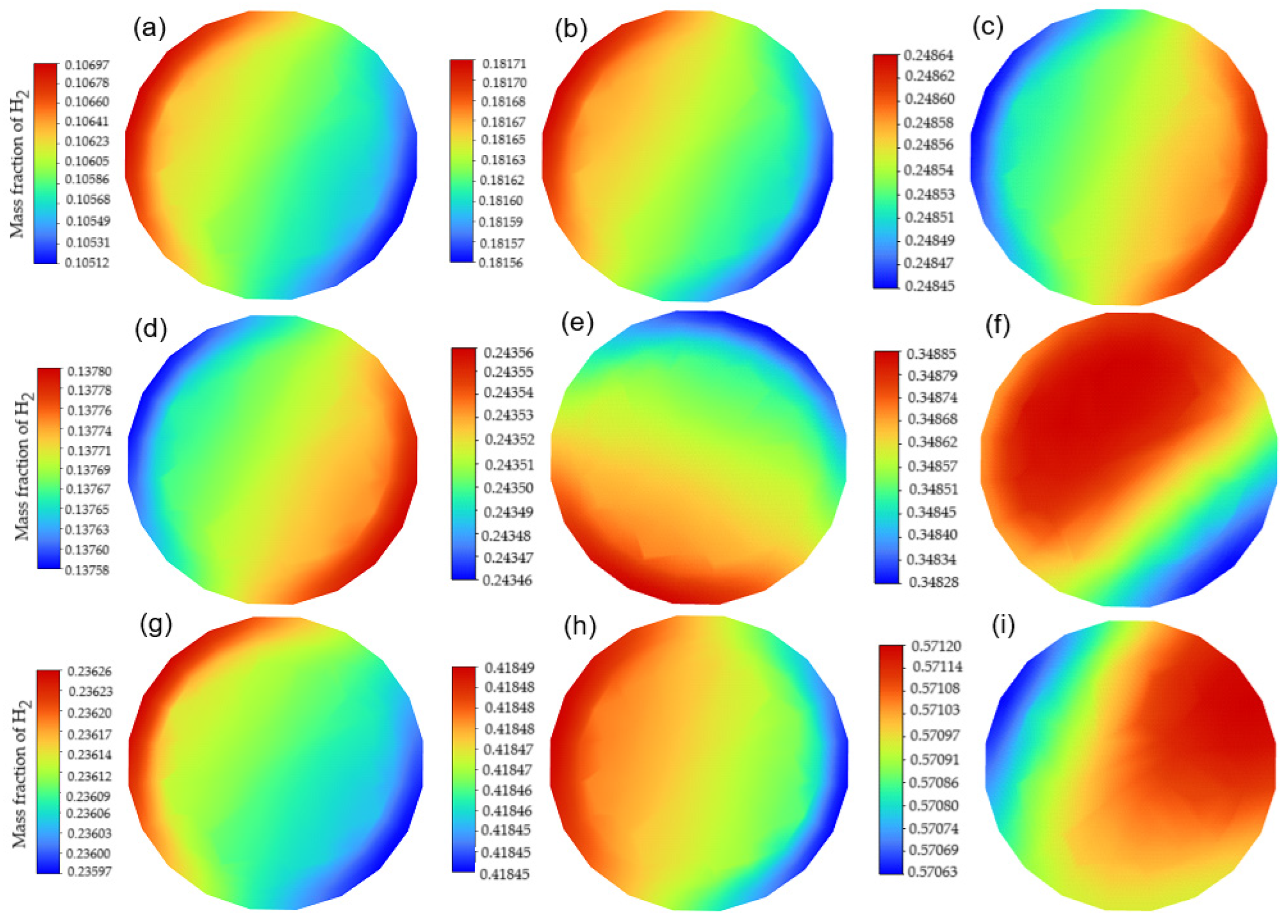
3.2. Impact of Nozzle Geometry

The simulations were extended to evaluate the performance of larger nozzle configurations, specifically with a diameter of 0.6 mm. Table 3 summarizes the results, with H2 mass fractions reaching up to 57.1% for higher inlet pressures.
While larger nozzles enabled higher hydrogen throughput, they also resulted in increased pressure drops and slightly less uniform mixing. Figure 5 shows how H2 diffused into the CH4 stream for a 0.6 mm nozzle.
The contours reveal more pronounced gradients compared to the 0.4 mm configuration, indicating a need for enhanced turbulence generation in larger nozzle setups.
The mixing homogeneity was evaluated by analyzing the variance in H2 concentration at the outlet. For the 0.4 mm nozzle geometry, the system consistently maintained a variance below 0.3%, regardless of the inlet conditions. For the 0.6 mm nozzle, the variance increased slightly but remained within acceptable limits for most cases. This highlights the robustness of the mixer design in maintaining consistent performance under varying operational scenarios.

3.3. Comparison of Simulation and Experimental Data

The comparison between the numerical simulation results and experimental data revealed a high degree of agreement, demonstrating the reliability of the computational model in predicting the behavior of the hydrogen–methane mixing system. The simulation cases (A1–A5) were designed to replicate the experimental conditions, including inlet pressures and H2 mass fractions, and the results were analyzed to quantify the accuracy of the predictions.
The numerical simulations accurately predicted the hydrogen mass fractions obtained in the experiments across all cases. The comparative analysis (Table 4) indicated that the average accuracy of the simulations relative to the experimental results was 98.47%, with an average accuracy error of 1.528%. This low error margin is within the typical benchmark of ±1% to ±2% for mixing devices, confirming the robustness of the CFD model.
The results indicate minimal deviations between simulated and experimental hydrogen mass fractions, with case A4 showing the highest accuracy at 99.79%. The consistency of the model across different operating conditions highlights its capacity to predict mixing dynamics reliably.
The slight differences observed between simulation and experimental results can be attributed to two primary factors: human and equipment errors. Equipment errors, including systematic errors associated with the gas chromatograph, are measurable and can be minimized through calibration and repeatability tests. On the other hand, human errors may arise during the preparation of the experimental setup or data collection.
Another potential source of deviation lies in the synchronization between the physical geometry of the experimental mixer and the computational mesh used in simulations. Small construction tolerances and mesh complexities can influence the accuracy of the model. Additionally, iterative tolerances in the CFD solver and the assumptions made during simulations, such as boundary conditions and material properties, contribute to the overall error.
The low average accuracy error underscores the strength of the CFD model in replicating real-world mixing scenarios. The findings validate the simulation approach and the design of the mixing device, demonstrating that the numerical model can effectively capture the intricate dynamics of hydrogen–methane blending.

3.4. System Optimization and Trade-Offs

This study highlights several trade-offs between mixing efficiency, pressure drop, and hydrogen throughput:
  • Smaller Nozzles (0.4 mm): Achieved highly uniform mixing with minimal pressure losses, making them ideal for applications requiring precise control of hydrogen concentration;
  • Larger Nozzles (0.6 mm): Enabled higher hydrogen mass fractions but required careful management of pressure and flow conditions to maintain mixing efficiency.
Future designs could explore hybrid nozzle configurations or adaptive systems that dynamically adjust nozzle diameters based on real-time flow conditions.

4. Conclusions

The integration of hydrogen–methane gas mixtures into existing energy systems represents a promising step toward achieving a carbon-neutral economy. This study investigated the performance of a novel mixing device designed for hydrogen (H2) and methane (CH4) blending, utilizing both experimental tests and numerical simulations. Hydrogen concentrations ranging from 5% to 18% were tested, and the quality of the resulting mixtures was validated using a specialized gas chromatograph. The results were compared with computational fluid dynamics (CFD) simulations, revealing a high degree of correlation and confirming the accuracy of the numerical model.
The mixing device demonstrated effective blending performance, maintaining H2 concentrations within the desired range for various inlet pressures and nozzle configurations. The device’s progressive injection design and internal flow deflectors ensured uniform mixing, with minimal concentration variation across the outlet pipe diameter. Tests with 0.4 mm and 0.6 mm nozzles highlighted key trade-offs; while the smaller nozzles provided highly uniform blending and lower pressure drops, the larger nozzles allowed for higher H2 throughput but required careful pressure management to sustain mixing efficiency.
The compatibility of the mixer with existing natural gas pipeline infrastructure makes it a practical solution for long-distance hydrogen transportation. The system operated efficiently within its designed flow limits, demonstrating its potential for large-scale deployment. Furthermore, the results underline the feasibility of hydrogen–methane gas mixtures as a transitional energy solution, leveraging existing infrastructure to accelerate the adoption of hydrogen in diverse applications while supporting global decarbonization goals.
This work establishes the presented mixing device as a reliable and efficient tool for blending hydrogen into methane streams. By ensuring uniform mixtures and adapting to varying operating conditions, the mixer addresses key challenges associated with hydrogen integration. The findings lay the groundwork for future studies to optimize mixer geometry, extend operational ranges, and validate performance under field conditions, further contributing to the transition to a carbon-neutral energy future.

Author Contributions

Conceptualization, Ş.I.S. and E.I.I.; methodology, E.I.I.; software, Ş.I.S. and B.F.M.; validation, Ş.I.S. and B.F.M.; formal analysis, E.I.I.; investigation, Ş.I.S.; resources, E.I.I.; data curation, Ş.I.S.; writing—original draft preparation, E.I.I.; writing—review and editing, E.I.I.; visualization, Ş.I.S.; supervision, E.I.I.; project administration, Ş.I.S.; funding acquisition, E.I.I. All authors have read and agreed to the published version of the manuscript.

Funding

This research was funded through the Core Program within the National Research Development and Innovation Plan 2022–2027, carried out with the support of MCID, grant 20N/2023, project PN 23 15 01 01 “Development and demonstration of a synergistic model of resilient operation of a hydrogen-based structure, using artificial intelligence”; acronym HyEnergy.

Data Availability Statement

All data are reported in this manuscript.

Conflicts of Interest

The authors declare no conflicts of interest.

References

  1. Bauer, C.G.; Forest, T.W. Effect of hydrogen addition on the performance of methane-fueled vehicles. Part I: Effect on S.I. engine performance. Int. J. Hydrogen Energy 2001, 26, 55–70. [Google Scholar] [CrossRef]
  2. Karim, G.A.; Wierzba, I.; Al-Alousi, Y. Methane-hydrogen mixtures as fuels. Int. J. Hydrogen Energy 1996, 21, 625–631. [Google Scholar] [CrossRef]
  3. Sierens, R.; Rosseel, E. Variable composition hydrogen/natural gas mixtures for increased engine efficiency and decreased emissions. J. Eng. Gas Turbines Power 2000, 122, 135–140. [Google Scholar] [CrossRef]
  4. Kong, M.; Feng, S.; Xia, Q.; Chen, C.; Pan, Z.; Gao, Z. Investigation of mixing behavior of hydrogen blended to natural gas in gas networks. Sustainability 2021, 13, 4255. [Google Scholar] [CrossRef]
  5. Sofian, M.; Haq, M.B.; Al Shehri, D.; Rahman, M.M.; Muhammed, N.S. A review on hydrogen blending in gas networks: Insight into safety, corrosion, embrittlement, and coatings. Int. J. Hydrogen Energy 2024, 60, 867–889. [Google Scholar] [CrossRef]
  6. Chugh, S.; Posina, V.A.; Sonkar, K.; Srivatsava, U.; Sharma, A.; Acharya, G.K. Modeling & simulation study to assess the effect of CO2 performance and emissions characteristics of 18% HCNG blend on a light duty SI engine. Int. J. Hydrogen Energy 2016, 41, 6155–6161. [Google Scholar] [CrossRef]
  7. Singh, A.P.; Pal, A.; Agarwal, A.K. Comparative particulate characteristics of hydrogen, CNG, HCNG, gasoline and diesel fueled engines. Fuel 2016, 185, 491–499. [Google Scholar] [CrossRef]
  8. Genovese, A.; Contrisciani, N.; Ortenzi, F.; Cazzola, V. On road experimental tests of hydrogen/natural gas blends on transit buses. Int. J. Hydrogen Energy 2011, 36, 1775–1783. [Google Scholar] [CrossRef]
  9. Luo, S.; Ma, F.; Mehra, R.K.; Huang, Z. Deep insights of HCNG engine research in China. Fuel 2020, 236, 116612. [Google Scholar] [CrossRef]
  10. Thakur, R.K.; Vial, C.; Nigam, K.D.P.; Nauman, E.B.; Djelveh, G. Static mixers in the process industries—A review. Chem. Eng. Res. Des. 2003, 81, 787–826. [Google Scholar] [CrossRef]
  11. Deng, J.; Ma, F.; Li, S.; He, Y.; Wang, M.; Jiang, L.; Zhao, S. Experimental study on combustion and emission characteristics of hydrogen-enriched compressed natural gas engine under idling condition. Int. J. Hydrogen Energy 2011, 36, 13150–13157. [Google Scholar] [CrossRef]
  12. Zidouni, F.; Krepper, E.; Rzehak, R.; Rabha, S.; Schubert, M.; Hampel, U. Simulation of gas–liquid flow in a helical static mixer. Chem. Eng. Sci. 2015, 137, 476–486. [Google Scholar] [CrossRef]
  13. Das, M.D.; Hrymak, A.N.; Baird, M.H. Laminar liquid–liquid dispersion in the SMX static mixer. Chem. Eng. Sci. 2013, 101, 329–344. [Google Scholar] [CrossRef]
  14. Melaina, M.W.; Antonia, O.; Penev, M. Blending Hydrogen into Natural Gas Pipeline Networks: A Review of Key Issues; Report number: NREL/TP-5600-51995; National Renewable Energy Laboratory (NREL): Golden, CO, USA, 2013.
  15. Haddadi, M.M.; Hosseini, S.H.; Rashtchian, D.; Olazar, M. Comparative analysis of different static mixers performance by CFD technique. Chin. J. Chem. Eng. 2019, 28, 672–684. [Google Scholar] [CrossRef]
  16. Ohkawa, K.; Nakamoto, T.; Izuka, Y.; Hirata, Y.; Inoue, Y. Flow and mixing characteristics of σ-type plate static mixer with splitting and inverse recombination. Chem. Eng. Res. Des. 2008, 86, 1447–1453. [Google Scholar] [CrossRef]
  17. Static Mixers. Available online: https://www.staticmixers.com (accessed on 10 November 2024).
  18. Pang, Z.; Chen, R.; Cao, Y. Performance analysis and optimization for static mixer of SCR denitration system under different arrangements. Energies 2022, 15, 8977. [Google Scholar] [CrossRef]
  19. Static Pipeline Mixers. Available online: https://westfallstaticmixers.com/ (accessed on 12 November 2024).
  20. Ghanem, A.; Lemenand, T.; Della Valle, D.; Peerhossaini, H. Static mixers: Mechanisms, applications, and characterization methods–A review. Chem. Eng. Res. Des. 2014, 92, 205–228. [Google Scholar] [CrossRef]
  21. Helical Mixers. Available online: https://www.primix.com (accessed on 12 November 2024).
  22. Model HT. Available online: https://www.stamixco-usa.com/helical (accessed on 12 November 2024).
  23. Bakker, A.; LaRoche, R.D.; Marshall, E.M. Laminar flow in static mixers with helical elements. In The Online CFM Book; 2000; p. 546. Available online: https://www.bakker.org/cfm/publications/cfmbook/lamstat.pdf (accessed on 14 November 2024).
  24. Ujhidy, A.; Nemeth, J.; Szépvölgyi, J. Fluid flow in tubes with helical elements. Chem. Eng. Process. 2003, 42, 1–7. [Google Scholar] [CrossRef]
  25. John, T.P.; Poole, R.J.; Kowalski, A.; Fonte, C.P. Viscoelastic flow asymmetries in a helical static mixer and their impact on mixing performance. J. Nonnewton. Fluid Mech. 2024, 323, 105156. [Google Scholar] [CrossRef]
  26. SS Low Flow Binary Tee Static Bed Mixer. Available online: https://www.analytical-sales.com/product/ss-low-flow-binary-tee-static-bed-mixer-housing-only/ (accessed on 15 November 2024).
  27. Chen, Z.; Dewees, D.; Gustafsson, L.M. CFD modelling of mixing tees—Design of a thermal sleeve, Special Focus—Valves, Pumps and Turbomachinery. Hydrocarb. Process. 2020, 21–25. Available online: https://becht.com/wp-content/uploads/2020/08/mixing_tees_Hydroprocessing.pdf (accessed on 12 November 2024).
  28. High Pressure Static Mixing Tee. Available online: https://www.idex-hs.com (accessed on 16 November 2024).
  29. Kok, J.B.; Van der Wal, S. Mixing in T-junctions. Appl. Math. Model. 1996, 20, 232–243. [Google Scholar] [CrossRef]
  30. General Purpose Mixers. Available online: https://www.sulzer.com/en/products/agitators-mixers-and-heat-exchangers/static-mixers/general-purpose-mixers (accessed on 18 November 2024).
  31. Fradette, L.; Tanguy, P.; Li, H.Z.; Choplin, L. Liquid/liquid viscous dispersions with a SMX static mixer. Chem. Eng. Res. Des. 2007, 85, 395–405. [Google Scholar] [CrossRef]
  32. Lowry, E.; Yuan, Y.; Krishnamoorthy, G. A new correlation for single-phase pressure loss through SMV static mixers at high Reynolds numbers. Chem. Eng. Process. 2022, 171, 108716. [Google Scholar] [CrossRef]
  33. BOPI Nr. 12/2023. Available online: https://www.osim.ro/images/Publicatii/Inventii/2023/inv_12_2023.pdf (accessed on 12 November 2024).
  34. Bostan, V. Modele matematice în inginerie: Probleme de contact. In Modelări și Simulări Numerice în Aero-Hidrodinamică; BonsOffices: Chișinău, Moldova, 2014; 470p, ISBN 978-9975-80-831-6. [Google Scholar]
  35. Fluent. Ansys Fluent Theory Guide; ANSYS Inc.: Canonsburg, PA, USA, 2022. [Google Scholar]
  36. Monea, B.F.; Ionete, E.I.; Spiridon, S.I. Experimental investigation and CFD modeling of slush cryogen flow measurement using circular shape capacitors. Sensors 2020, 20, 2117. [Google Scholar] [CrossRef] [PubMed]
Figure 1. Schematic representation of the mixing system, developed to illustrate the arrangement of key components, including the static mixer, injection nozzles, and gas chromatograph. The diagram highlights the flow paths of hydrogen and methane and their interaction points within the mixing chamber.
Fuels 06 00028 g001
Figure 2. Mixer 3D model and mesh: (a) mixer model; (b) mesh—mixer inlet; (c) mesh—section outlet mixer; (d) image of the device before final assembly.
Fuels 06 00028 g002
Figure 3. H2 mass fraction: (a) case A1; (b) case A2; (c) case A3; (d) case A4; (e) case A5.
Fuels 06 00028 g003
Figure 4. Pressure distribution (example—case A2).
Fuels 06 00028 g004
Figure 5. H2 mass fraction: (a) case B1; (b) case B2; (c) case B3; (d) case B4; (e) case B5; (f) case B6; (g) case B7; (h) case B8; (i) case B9.
Fuels 06 00028 g005
Table 1. Types of static mixers for hydrogen–methane blending.
Mixer
Type
Primary
Applications
AdvantagesDisadvantagesKey
References
Tab or
Plate Mixers
-
Gas–Gas Mixing;
-
Liquid–Gas Mixing;
-
Liquid–Liquid Mixing (miscible/immiscible liquids);
-
Chemical Reactions
-
Simple, low-cost design;
-
Suitable for continuous processes;
-
Low energy requirements;
-
Operable in turbulent and laminar flows;
-
Easy to clean in basic setups.
-
Limited mixing efficiency for high-viscosity or complex systems;
-
Prone to fouling and deposit buildup;
-
High-shear forces may degrade sensitive components;
-
Limited adaptability once installed
[10,15,16,17,18,19,20]
Helical
Mixers
-
Gas–Gas Mixing;
-
Heat Transfer Applications;
-
Multiphase Flow Processing;
-
Polymer Mixing
-
High mixing performance, especially in small-diameter pipelines;
-
Enhanced heat transfer capability;
-
Customizable flow regime (laminar or turbulent);
-
Compact and efficient for pipeline integration.
-
High-pressure drop in dense or high-viscosity fluids;
-
Increased energy consumption;
-
Prone to fouling in systems with suspended solids;
-
Limited scalability in very large setups.
[4,9,12,21,22,23,24,25]
Tee
Mixers
-
Rapid Batch Mixing;
-
High-Pressure Systems;
-
Laboratory Use;
-
Flow Control Systems.
-
Rapid and localized mixing;
-
Compact and easy to install;
-
High-pressure tolerance;
-
Minimal maintenance requirements.
-
Limited efficiency in large systems;
-
Performance highly dependent on pressure and flow dynamics;
-
Not scalable for continuous industrial processes.
[5,26,27,28,29]
Cartridge
Mixers
-
Gas–Gas Mixing;
-
Liquid–Gas Mixing;
-
Large-Scale Industrial Blending;
-
Oil and Gas Applications.
-
Modular and scalable design;
-
Customizable internal geometry for different blending needs;
-
Lower pressure drops in optimized setups;
-
Reduced shear stress, suitable for delicate blends.
-
Susceptible to fouling and clogging in prolonged use;
-
High initial cost and maintenance expenses;
-
Requires detailed monitoring for optimal performance.
[9,13,15,30,31,32]
Multi-Stage
Mixers
-
Gas–Gas and Gas–Liquid Blending;
-
Multi-Component Reactions;
-
Applications Requiring Gradual Mixing.
-
Ability to incrementally mix components;
-
Reduces pressure drop per stage compared to single-stage systems;
-
Improved control over mixing dynamics.
-
More complex design and installation;
-
Increased space and cost requirements;
-
Maintenance can be challenging in multi-stage setups.
[5,9,10]
Baffled Pipe
Mixers
-
Gas–Liquid and Gas–Gas Mixing;
-
Pipeline Transport of Multi-Phase Systems;
-
Applications Requiring Homogeneous Distribution.
-
High mixing efficiency across diverse flow regimes;
-
Enhanced distribution of gases and liquids;
-
Durable and reliable for industrial applications.
-
High turbulence can lead to energy losses;
-
Limited adaptability for low-pressure systems;
-
Complex maintenance due to internal elements.
[4,12]
Table 2. Summarized simulation cases.
CaseH2 Mass Fraction
(%)
H2 Inlet Pressure
(kPa)
CH4 Inlet Pressure
(kPa)
A15.45–5.64150130
A28.01–8.07150115
A310.1–10.2150110
A414.4–14.6180110
A517.5–17.8200110
Table 3. Summarized simulation cases for nozzle geometry having 0.6 mm diameter.
CaseH2 Mass Fraction
(%)
H2 Inlet Pressure
(kPa(r))
CH4 Inlet Pressure
(kPa(r))
B110.6150130
B218.2200130
B324.8250130
B413.8150120
B524.3200120
B634.9250120
B723.6150110
B841.8200110
B957.1250110
Table 4. Comparative analysis: simulation vs. experimental data.
CaseH2 Mass Fraction
(%)
Accuracy
(%)
Accuracy Error
(%)
SimulatedExperimental
A15.45–5.645.54–5.7897.972.02
A28.01–8.078.18–8.2397.982.01
A310.10–10.2010.25–10.4498.111.88
A414.40–14.6014.46–14.6099.790.21
A517.5–17.817.6–18.2598.481.52
Disclaimer/Publisher’s Note: The statements, opinions and data contained in all publications are solely those of the individual author(s) and contributor(s) and not of MDPI and/or the editor(s). MDPI and/or the editor(s) disclaim responsibility for any injury to people or property resulting from any ideas, methods, instructions or products referred to in the content.

