1. Introduction
As technology advances, there is a global surge in the number of vehicles on the roads. However, a considerable portion of these vehicles still relies on fossil fuels. This reliance has triggered a surge in fossil fuel consumption, resulting in a rapid depletion of these resources. Consequently, developed nations, facing high energy demands, are exerting increased pressure on countries abundant in fossil fuel reserves to meet their energy needs, often leading to destabilization in these regions [
1,
2].
The utilization of alternative fuels in internal combustion engines has gained increasing significance in contemporary times. This trend is primarily driven by the rising demand for fuel alongside the proliferation of vehicles, coupled with the introduction of emission standards by certain countries. Among the various alternative fuels under investigation by researchers, hydrogen stands out as a promising candidate. It is the most abundant element in nature and can be procured from renewable energy sources, offering exceptionally low emission levels. For instance, projections from the French oil market report suggest that by 2050, approximately 25% of passenger vehicles and 20% of non-electric rail transport could be powered by hydrogen, potentially reducing daily oil consumption by up to 20% [
3,
4]. Similar initiatives promoting the use of hydrogen are evident in other nations as well. However, the widespread adoption of low-carbon or carbon-free alternative fuels like hydrogen necessitates the establishment and commercialization of adequate infrastructure. Hydrogen not only serves as a source of energy capable of mitigating carbon-based emissions but also boasts high energy efficiency. Moreover, aside from its role as an energy carrier, hydrogen is poised to emerge as a viable alternative to petroleum in the foreseeable future, owing to its ability to be generated from renewable energy sources [
5,
6,
7].
An ICE with hydrogen could be an economical solution interesting for LCV as it uses the same industrial assets of current Diesel or gasoline thermal engines while achieving the requested high power. Moreover, an H2 ICE has less purity demand than the alternative solution, PEMFC. In this framework, HORSE company, which is developing worldwide ICEs, has decided to launch advanced engineering activities to adapt current Diesel engines to hydrogen combustion. The aim is to keep the industrial asset as much as possible while achieving very stringent emissions levels (CLOVE B), best-in-class performance and efficiency [
8,
9].
This research aims to employ computational fluid dynamics to observe the progression and enhancement of hydrogen injection, mixing, and combustion within the cylinder. Our goal is to gain a deeper understanding of in-cylinder flow dynamics and combustion behavior. Through this investigation, we intend to gather fundamental parameter data crucial for controlling combustion and emissions in pure hydrogen internal combustion engines (ICE). Additionally, we aim to propose innovative strategies to advance the practical implementation and development of hydrogen ICE technology.
The current state of the art in hydrogen internal combustion engine (H2 ICE) technology is marked by a degree of confusion regarding the optimal methodology for transitioning a conventional internal combustion engine (ICE) into one that operates on hydrogen. This study endeavors to address this gap by meticulously investigating several key parameters of design. The primary objective is to delineate a comprehensive strategy for achieving optimal mixing conditions necessary for the successful transformation outlined within the conditions. By systematically exploring various parameters and their interrelationship, this research aims to contribute valuable insights toward the development of effective methodologies for transitioning ICEs into H2 ICEs [
10].
There are several studies that analyze the use of diesel–hydrogen dual fuels; thus, in [
11], the authors developed and validated a diesel/hydrogen dual-fuel combustion mechanism, showing that pilot and main injection timing significantly impact combustion characteristics, emissions, and engine performance.
In [
12], the authors replaced diesel with low-carbon hydrogen in railway applications, which led to a 56% reduction in CO
2 emissions, despite the hydrogen-fueled engine consuming nearly twice as much energy and experiencing a decrease in traction power from 600 to 400 kW.
Study [
13] demonstrated that converting diesel engines to operate on diesel–hydrogen fuels is technically feasible, leading to increased energy efficiency, reduced emissions, and lower fuel costs, with methanol-based hydrogen conversion offering a cost-effective and environmentally friendly alternative to conventional diesel.
The study of [
14] investigated a 12.8 L six-cylinder turbocharged diesel engine modified for hydrogen use, introducing a jet ignition pre-chamber system to enable four operational modes: diesel-like diffusion (M1), mixed diffusion/premixed (M2), gasoline-like premixed with jet ignition (M3), and HCCI-like premixed without jet ignition (M4). Computational modeling with GT-POWER and Wiebe models shows that jet ignition significantly enhances hydrogen combustion efficiency and emission performance, suggesting hydrogen as a viable alternative fuel for future internal combustion engines.
There are several studies that analyze the use of hydrogen in piston engines, engine conversion, or its use as a dual fuel [
15,
16,
17,
18].
Furthermore, challenges related to engine durability and fuel efficiency continue to drive research in hydrogen ICEs. As hydrogen combustion characteristics differ significantly from those of traditional fossil fuels, optimizing the combustion process to achieve efficient power output while minimizing emissions is crucial. Advances in fuel injection systems, such as optimizing nozzle configurations and injector placement, play a significant role in improving hydrogen mixing and combustion inside the cylinder. In this context, studies have explored the impact of various nozzle designs on hydrogen combustion, suggesting that fine-tuning injection parameters is essential for ensuring homogeneous combustion and preventing issues like pre-ignition and knock [
19]. Moreover, the integration of advanced engine materials capable of withstanding the high temperatures and pressures associated with hydrogen combustion is an area of active research. Materials with enhanced resistance to thermal stresses and hydrogen embrittlement will be critical for the long-term reliability and performance of hydrogen-fueled ICEs [
20].
Additionally, the need for a robust hydrogen infrastructure remains a major hurdle for large-scale adoption. Current hydrogen production methods, such as electrolysis and steam methane reforming, must be scaled up to meet the anticipated demand for hydrogen fuel in the transportation sector. Furthermore, hydrogen storage and distribution systems must be enhanced to ensure the efficient and safe transportation of hydrogen to fueling stations. Research into improving hydrogen storage technologies, such as high-pressure tanks and cryogenic storage, is vital to support the widespread use of hydrogen as a fuel [
21].
In [
22], the authors investigated the interaction between external and internal hydrogen in the “cylinder-piston rings” friction couple of spark ignition engines. Under high temperature and pressure conditions, the oil in the combustion chamber decomposes, forming small amounts of water that generate external hydrogen. The removal of hydrogen from the piston rings reduces structural heterogeneity, residual stresses, and uneven physical–chemical properties of the surface layers, leading to lower stress concentrations and improved performance of the friction couple. The research highlights the role of layered nanostructures, such as graphite inclusions in nodular cast iron, in effectively accumulating hydrogen. These findings provide valuable insights into strategies for reducing hydrogen-induced wear and improving the friction performance of engine components.
Addressing these infrastructure challenges is key to ensuring the practical implementation of hydrogen ICE technology on a global scale.
By systematically exploring these parameters, the study aims to develop a comprehensive design framework that serves as a guideline for engineers converting traditional internal combustion engines (ICEs) to operate on hydrogen. This framework incorporates best practices and optimal settings for each parameter to enhance engine performance and efficiency. Additionally, it seeks to provide insights into achieving higher power outputs and improved fuel efficiency without compromising safety or increasing emissions. The study also focuses on reducing harmful emissions, particularly NOx, through strategic design and operational adjustments. Furthermore, it aims to advance the technological understanding of the interdependencies between various design parameters and their collective impact on overall engine performance.
2. Materials and Methods
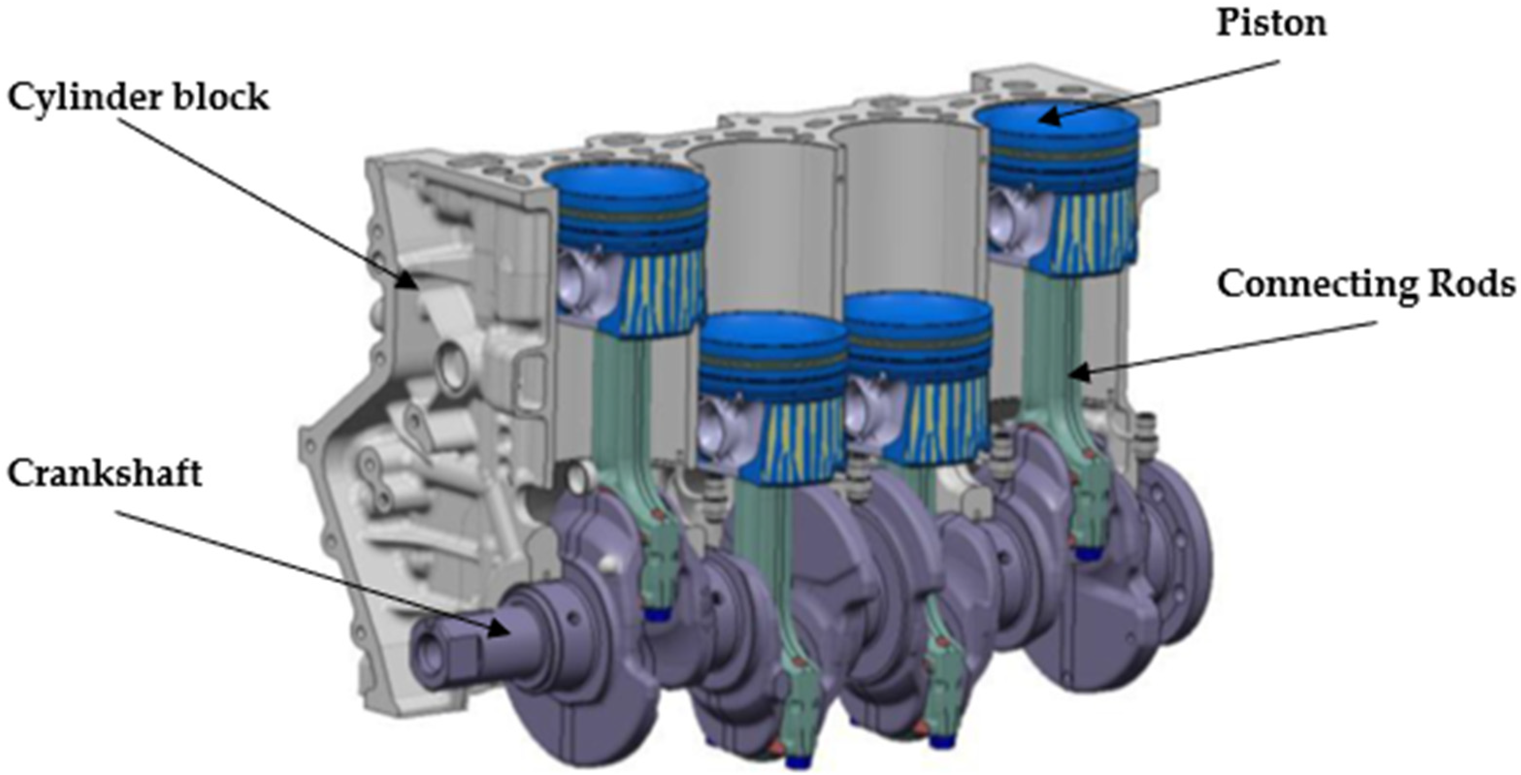
The base of the study is a 2.0 L automotive diesel 4 stroke engine with a flat roof cylinder head, a direct central injector, intake ducts designed for a swirl aerodynamic motion and a classical diesel bowl piston, see
Figure 1.
The adaptation of this engine to an H2 ICE contains the introduction of a direct H
2 injector, an H
2 spark plug, and the adaptation of CR.
Table 1 contains information on the engine details that were fixed.
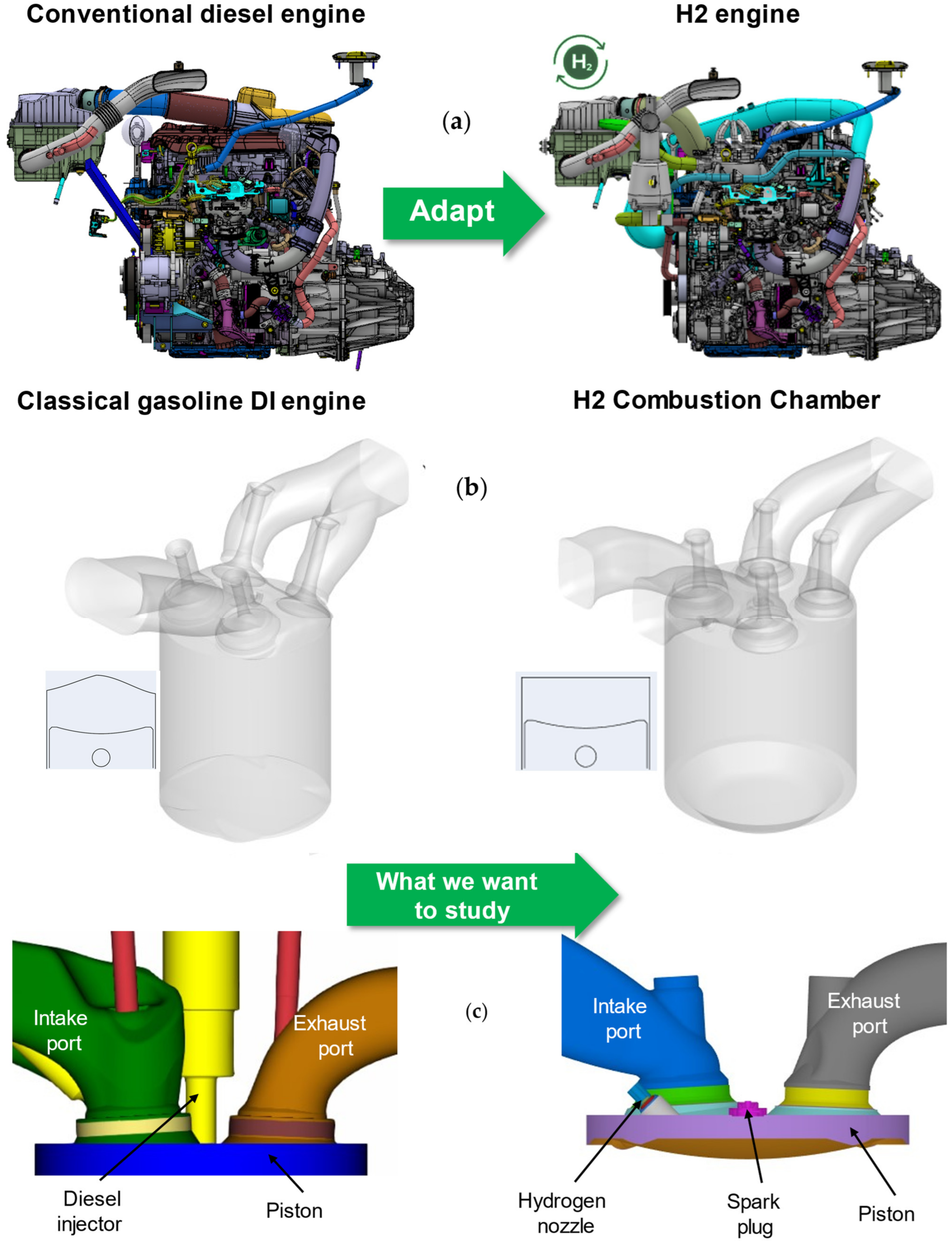
In
Figure 2, the design of the diesel engine and its adaptation to run on hydrogen is shown. The modifications to the fuel supply system and the combustion chamber can be observed, illustrating the necessary changes to accommodate hydrogen as a fuel source.
In
Figure 2a, a conventional diesel engine is presented alongside an adapted hydrogen (H
2) engine. The modifications primarily focus on replacing the diesel injection system with a hydrogen-specific fuel delivery system, ensuring proper air–fuel mixing and optimizing combustion characteristics for hydrogen.
Figure 2b presents a comparison between a classical gasoline direct injection (DI) engine and a hydrogen combustion chamber. The geometry of the intake and exhaust ports, along with the fuel injection system, are adapted to facilitate hydrogen injection and ignition. Unlike traditional gasoline DI engines, where fuel is injected directly into the combustion chamber, hydrogen combustion often requires different injector positioning and mixture preparation to prevent abnormal combustion phenomena such as pre-ignition and backfiring.
Figure 2c highlights the structural differences between a conventional diesel engine combustion chamber and a hydrogen-adapted combustion chamber.
2.1. CFD Modeling and Boundary Conditions
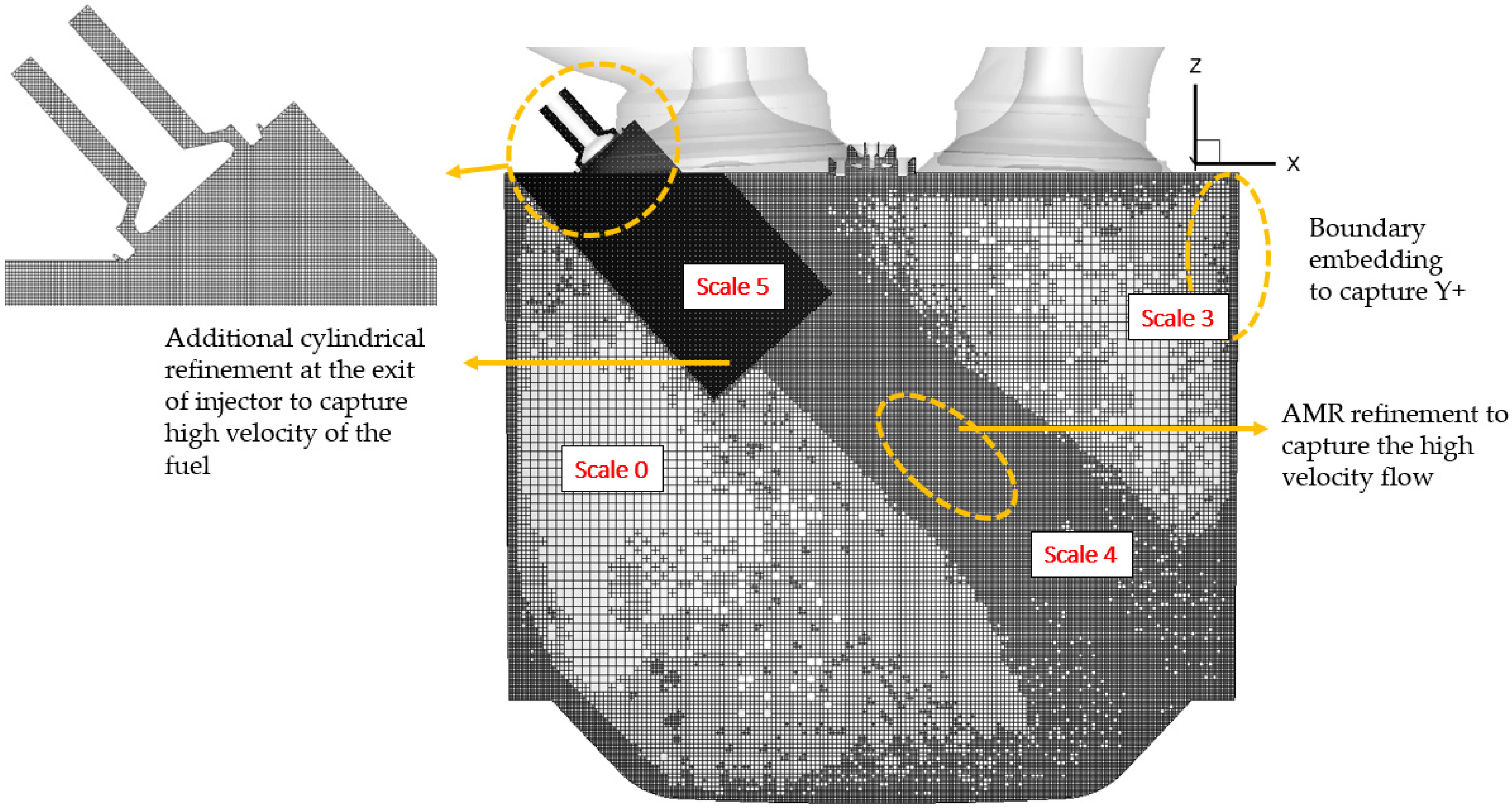
The CFD aero and mixing modeling method is based on CONVERGE software v4.0.1 and was developed to be a compromise between fidelity and computation. The mesh development starts with a base size of 0.5 mm, where we add various mesh refinement levels. The different region of our dataset is illustrated in
Figure 3, with corresponding scales detailed in
Table 2.
The use of distinct refinement scales helps minimize computational costs and time requirements while maintaining accuracy in calculations specifically developed for hydrogen injection. The automatic mesh is limited to 15 million cells.
The solver employed in this study is a widely used RANS k-epsilon model, with adaptation specifically designed for hydrogen. These adaptations encompass all the unique characteristics and requirements of hydrogen, ensuring the solver effectively captures the intricacies of hydrogen behavior within the system [
23].
Hydrogen combustion has unique characteristics that require specific adjustments to the standard k–ε model:
High Diffusivity of Hydrogen: Hydrogen has a significantly higher diffusivity compared to hydrocarbon fuels. This enhances mixing with air but requires modifications to turbulence modeling constants to accurately represent the diffusion-driven effects on the turbulence structure.
Lower Density and High Flame Speed: Hydrogen–air mixtures have lower densities and higher flame speeds, impacting the interaction between turbulence and flame propagation. The k–ε model must account for these effects when predicting turbulence levels, especially near flame fronts.
Heat Release and Buoyancy Effects: Hydrogen combustion involves rapid heat release, which can induce strong buoyancy forces in the flow. This can alter the turbulence production and dissipation mechanisms, requiring tailored buoyancy source terms in the model.
Lean Combustion Conditions (Lambda 2.5): Lean hydrogen combustion operates far from stoichiometric conditions, which changes the turbulence–chemistry interaction compared to stoichiometric or rich combustion of other fuels. Adjustments are needed to handle the influence of turbulence on the chemical reaction rate.
In addressing boundary conditions within specified limits, the adaptation for hydrogen injection involves employing a pressure inlet featuring a real valve law to accurately replicate the hydrogen mass flow rate and flow dynamics. Our findings demonstrate that optimizing nozzle pressure while accounting for injector pressure loss and refining cell sizes contributes significantly to representing the hydrogen jet with fidelity. Additionally, the simulation’s other boundary condition is tied to the operational parameters, as detailed in
Table 3. Specifically, our analysis focuses on the operating point at 3500 RPM, aligning with the rated power operating point of our engine. Notably, we exclusively consider the pure lean lambda 2.5 condition, recognizing its pivotal role as the most constraining condition from a mixing perspective. This point is chosen as the worst case for the mixing process, less time and high hydrogen quantity.
2.2. Hydrogen (H2) Mixing and Combustion Quality Indicator
To evaluate the effectiveness of different conceptual approaches under scrutiny, it is imperative to employ indicators that can assess the quality of mixing [
24]. Following examination, four relevant indicators were identified:
Aero level of motion: This usual indicator evaluates the level of tumble or swirl present in the system, depending on the specific case being studied. A higher level of aero motion at the start of mixing could indicate a better mixing potential and/or a better turbulence production when the high level is close to TDC.
Swirl and
Tumble values are calculations that are directly based on the Converge Formula as an angular speed ratio.
The angular speed on x and z are calculated from the angular momentum,
Li, and the moment of inertia,
Ii, as:
Turbulent Kinetic Energy (TKE): TKE assesses the turbulence within the combustion chamber, primarily to gauge the conversion of aero motion into energy for combustion. Consequently, it serves as an indicator for the combustion process; higher TKE values signify quicker combustion. The value is calculated with Converge formula description as the mass average transported TKE, as we use a k–epsilon RANS turbulence model.
Homogeneity index of the mixture: This indicator measures the homogeneity of mixture within the combustion chamber. As the mixture distribution near the TDCF follows a normal distribution, the formula is:
A value closer to 1 indicates better homogeneity, suggesting statistical proximity to a perfect mixture.
High Equivalence Ratio: This indicator quantifies the presence of rich pockets in the combustion chamber using the formula:
From the literature [
25,
26,
27,
28,
29], it is established that the autoignition probability is increasing a lot when lambda is below 1.6. This indicator is aiming to check that the mixing process decrease these rich pockets as fast as possible to not let the ignition process to occur during the compression stroke. Lower values of this indicator are then preferable close to TDCF, with 0 indicating the absence of rich zones.
3. Results and Discussions
This research is expected to make significant contributions to the field of H2 ICE technology by providing a clear and evidence-based roadmap for transitioning conventional diesel ICEs to hydrogen fuel.
3.1. Tumble vs. Swirl
Starting from a Diesel engine and considering a transition to a different air motion configuration can be a complex endeavor. In this case, the focus is on conserving the swirl motion, a crucial aspect of engine performance. The initial question revolves around whether maintaining this swirl motion is feasible or if a shift to a tumble duct design is necessary, particularly concerning the engine’s air motion into a flat head configuration.
Figure 4 presents the concept of tumble vs. swirl.
Figure 4 effectively illustrates the difference between tumble and swirl motion in an internal combustion engine. The tumble motion, shown in
Figure 4a, involves airflow moving in a vertical loop perpendicular to the cylinder axis, which enhances air–fuel mixing and improves combustion efficiency, particularly in high-speed engine conditions. The plus sign in the diagram suggests an increase in turbulence intensity, further aiding mixture preparation. In
Figure 4b, the swirl motion depicts the airflow rotating around the cylinder axis in a horizontal circular pattern. This type of motion improves mixture stratification and combustion stability, making it more suitable for low-speed engine operation. By comparing these two airflow characteristics,
Figure 4 highlights how different flow dynamics influence combustion efficiency under varying engine conditions.
To address this, a comprehensive parametric study becomes essential. This study encompasses various factors such as adapting the original port to accommodate the hydrogen injector, optimizing the placement of the spark plug, exploring different injection methods (central or lateral), and even experimenting with alterations in piston shape.
Through meticulous analysis and testing, it becomes evident that the optimal swirl design diverges significantly from the reference tumble design.
Figure 5 demonstrates a clear comparison between the performance metrics of the swirl-optimized design (green dashed line) and the traditional tumble reference design (red dashed line). Here is a summary of the key observations from the chart:
- ○
The swirl design exhibits a significantly higher swirl ratio, while the tumble design maintains a higher tumble ratio.
- ○
The transition points for the two designs clearly highlight the optimization intent for specific flow characteristics.
TKE—Turbulent Kinetic Energy (
Figure 5b):
- ○
The tumble design shows a peak in TKE earlier, while the swirl design sustains higher TKE levels over a broader range, indicating better energy distribution for mixing.
- ○
The swirl design (S) sustains higher H2 equivalence ratios compared to the tumble design (T), showcasing better mixing efficiency and potential for lean combustion strategies.
- ○
The swirl design achieves a superior homogeneity index compared to the tumble design, indicating more uniform mixing and a better-prepared charge for combustion.
Figure 5.
Comparison between an optimized swirl design and a tumble duct design for H2 mixing. (a) Tumble vs Swirl; (b) TKE (Turbulent Kinetic Energy); (c) High Equivalence Ratio; (d) Homogeneity Index.
Figure 5.
Comparison between an optimized swirl design and a tumble duct design for H2 mixing. (a) Tumble vs Swirl; (b) TKE (Turbulent Kinetic Energy); (c) High Equivalence Ratio; (d) Homogeneity Index.
In essence, this parametric study underscores the complexity of engine design optimization and highlights the importance of adaptability and innovation in achieving superior performance and efficiency.
In the case of maintaining a swirl motion within the engine, it is crucial to consider its impact on the mixing of hydrogen with air. One significant observation is that the piston motion does not disrupt the aerodynamic flow, which, unfortunately, does not aid in effectively mixing the hydrogen with the air. Consequently, a substantial portion of the mixture remains excessively rich, as indicated by the High Equivalence Ratio indicator. Additionally, the Homogeneity Index of the richness indicates poor uniformity throughout the mixture.
Another notable finding is the low Turbulent Kinetic Energy (TKE) during the end of the compression stroke. This signifies that the aerodynamic motion is conserved and does not transform into turbulence. While this may seem beneficial in some regards, it can potentially impact combustion speed. Although this effect is less pronounced in the case of hydrogen combustion, it remains a factor to consider in overall engine performance and efficiency.
These observations underscore the intricate balance between aerodynamic flow, mixing efficiency, and combustion dynamics in engine design. Achieving optimal performance requires careful consideration and adjustment of these factors to ensure efficient fuel–air mixing and combustion, ultimately leading to improved efficiency and reduced emissions.
3.2. Lateral vs. Central Injection
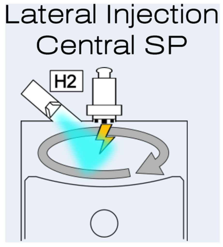
As established, the most effective aerodynamic motion in this context is the tumble motion; this chapter focuses on comparing the impacts of lateral injection and central injection within the same technical framework. Specifically, we maintain a constant flat cylinder head, identical piston specifications, and the same port design across all simulations. In
Figure 6, the lateral injection concept is presented.
Figure 7 clearly demonstrates that lateral injection results in more effective mixing of hydrogen within the tumble motion compared to central injection. This finding is consistent and reproducible across various types of tumble duct designs. The alignment of the injection jet with the direction of the tumble motion significantly amplifies the tumble effect. This enhancement is observed not only during the injection phase but also throughout the subsequent conversion of tumble into turbulence. This amplification appears to play a critical role in achieving optimal mixture preparation.
In particular, the high equivalence ratio (indicating regions of overly rich mixtures) decreases substantially during the compression phase. Concurrently, the Richness Homogeneity Index, which measures the uniformity of the fuel–air mixture, shows significant improvement. These observations suggest that the orientation and method of injection profoundly influence the efficiency and quality of the combustion process, with lateral injection offering distinct advantages over central injection in enhancing tumble motion and ensuring better fuel mixture preparation.
The impact of the aerodynamic motion level, specifically focusing on tumble motion, is studied. To illustrate this parameter, we analyze different tumble levels generated by various tumble ports
Figure 8, all using the same lateral injector position, the same piston designs, and a flat cylinder head combustion chamber.
Figure 9 demonstrates that Port 1 exhibits the least effective performance compared to the other solutions presented; it produces the poorest mixing, with the highest number of rich pockets and the lowest richness homogeneity index. In contrast, Ports 2, 3, and 4, despite generating similar levels of tumble, show differences in mixing quality. This indicates that the injection process must be well-coordinated with the tumble generated by the duct design. Our findings suggest that duct design is closely linked to injector placement in achieving optimal homogeneity.
In addition to studying tumble, we also investigated variations in swirl motion and other aerodynamic parameters. Our conclusions are consistent across these different types of aero motion: initially, higher levels of aerodynamic motion improve mixing quality. Subsequently, small variations in aero motion must be aligned with the injection process to maximize the benefits of aerodynamic motion in generating a well-mixed fuel–air mixture.
Overall, our study indicates that both the design of the ports and the positioning of the injector play crucial roles in optimizing the mixture preparation in hydrogen ICEs. By carefully tuning these parameters, it is possible to achieve significant improvements in combustion efficiency and performance.
3.3. Piston Shape Design
It is well-documented that the lenticular piston is optimal for a pent roof design. In this chapter, we extend this analysis to flat roof configurations. To verify this, we conducted comparative tests involving three different piston designs: Piston 2 with a flat bowl (yellow), Piston 3 with a smooth diesel bowl (red), and a deep impact piston based on the Piston 1 shape (green). These designs are illustrated in
Figure 10 [
30].
All tests were performed under identical conditions, maintaining the same tumble port configuration, lateral injector position, and a constant compression ratio (CR) of 11. The piston positions were adjusted to ensure these parameters were consistent.
The variation in piston shapes resulted in different levels of tumble. Our analysis indicates that increased tumble correlates with a higher Homogeneity Index and a lower High Equivalence Ratio indicator. These findings confirm that variations in piston shape significantly impact tumble levels, thus affecting the overall performance. Specifically, the results underscore the suboptimal performance associated with certain piston shapes [
31].
Simulation results, illustrated in
Figure 11, reveal significant differences in tumble levels, TKE, high equivalence ratio, and homogeneity index generated by each piston shape. The tumble profiles (top left graph) show that all piston designs generate a substantial tumble motion, with Piston 1 (green) producing the highest tumble peak just before top dead center (TDC). The TKE profiles (top right graph) indicate that Piston 1 (green) maintains higher TKE levels during the critical injection phase, suggesting more effective energy transfer from tumble motion. The high equivalence ratio profiles (bottom left graph) show that Piston 1 (green) results in a lower high equivalence ratio, indicating fewer rich mixture zones and, thus, a more favorable combustion environment. The homogeneity index profiles (bottom right graph) reveal that Piston 1 (green) achieves the highest homogeneity index, indicating the most uniform hydrogen–air mixture. Overall, Piston 1 (green) demonstrates superior performance in generating higher tumble and TKE, leading to better hydrogen mixing and more homogeneous air–fuel distribution.
This study extends the understanding of piston design impact from pent roof to flat roof configurations, emphasizing the importance of optimizing piston shapes for better hydrogen mixing. Piston 1, with its flat bowl design, showed the most promising results, enhancing tumble, TKE, and mixture homogeneity, thus improving overall combustion efficiency. Future work should explore additional piston geometries and their effects under various operating conditions to further enhance the efficiency and performance of hydrogen-fueled internal combustion engines.
3.4. Coanda Effect
The Coanda effect refers to the tendency of a fluid jet to stay attached to a nearby surface, even when the surface curves away from the initial jet direction. This phenomenon occurs due to the formation of low-pressure regions as the fast-moving fluid entrains surrounding air or gas, creating an asymmetric pressure distribution that “pulls” the jet toward the surface.
In the extant literature, investigations have uniformly employed a fixed nozzle penetration depth, which has inadvertently induced the Coanda effect in the hydrogen gas flow, as illustrated in
Figure 12. This effect occurs when the hydrogen jet, upon exiting the nozzle, adheres to a nearby boundary or structure rather than dispersing symmetrically. The influence of the Coanda effect can significantly alter jet trajectory, mixing characteristics, and local turbulence intensity, impacting fuel–air mixing efficiency and combustion performance in engine applications.
This phenomenon results in a fraction of the hydrogen gas adhering to the cylinder head, as evidenced in
Figure 13a. It can have a big drawback for pre-ignition propensity as it puts the hydrogen close to hot surfaces (spark plug and exhaust valves). An augmentation of the nozzle penetration to 8 mm, illustrated in
Figure 13b, is posited to obviate the Coanda effect, thereby permitting a subsequent evaluation of its influence on the gas mixing dynamics [
26,
32].
In the context of identical intake ports featuring the same level of tumble, mitigating the Coanda effect was found to enhance mixing efficiency, as presented in
Figure 14. Despite the hydrogen jet experiencing less modification, it fails to generate increased tumble both during and post-injection. Concurrently, reducing the Coanda effect maintains turbulence within the flow throughout injection, resulting in higher turbulent kinetic energy (TKE).
During the tumble TKE conversion phase, a greater proportion of tumble energy is channeled into hydrogen mixing, leading to a notable decline in the High Equivalence Ratio (ER) indicator and a faster increase in the richness homogeneity index. This improved efficiency during the conversion phase is attributed to an increased velocity of hydrogen, as evidenced in
Figure 13. Consequently, nearing spark advance, slightly superior H
2 mixing is achieved without any Coanda.
However, while a deeper penetration may yield a reduction in the Coanda effect, it poses challenges in terms of temperature on the hydrogen injector nozzle. Alternative solutions such as injector caps or deflectors offer viable means to alleviate the Coanda effect, thereby ensuring injector compliance and optimal performance.
3.5. Pent Roof vs. Flat Roof
The pent roof combustion chamber is often preferred in modern high-performance engines due to its efficiency in airflow, heat retention, and the ability to accommodate more valves for better breathing of the engine. The flat roof design, while simpler and potentially less expensive to manufacture, does not offer the same level of performance benefits [
33,
34]. The concept of pent vs. flat roof is presented in
Figure 15a.
This chapter provides a comparison between the previously discussed flat roof cylinder head illustrated in
Figure 15b and a conventional pent roof cylinder head, commonly used for tumble flow design. An alternative technical configuration for a hydrogen internal combustion engine (H2 ICE) was developed to facilitate this comparison. This configuration incorporates a duct connected to the pent roof cylinder head and features a centrally located injector and spark plug, as illustrated in
Figure 15c. It is the only way to construct the cylinder head with a valve train, injector and spark plug in such a pent roof configuration. To ensure a more equitable comparison, several parameters were standardized across both designs, including the piston, compression ratio (CR), and injector nozzle. The intake ports and the roof chamber are then different.
The comparison in
Figure 16 indicates that the ports adapted to the pent roof cylinder head generate lower tumble.
Consequently, it is challenging to determine whether the poor homogeneity results are more attributable to the pent roof design itself or to the reduced tumble observed with this configuration compared to the flat roof design. The high increase in TKE during injection is due to the central injector position as shown in paragraph 3.2, but that is not helping the mixing. Conversely, it is noted that the high equivalence ratio achieved with the pent roof is not unfavorable, as it was zero with the flat roof. Thus, it is difficult to conclusively determine if one design is superior to the other. The pent roof design should be optimized further: the tumble level and an injector cap could be the main features. However, in the context of a diesel engine conversion, this suggests that utilizing a flat roof head with a well-designed tumble duct could be a viable solution for hydrogen mixing.


