Article

Forming Ni-Fe and Co-Fe Bimetallic Structures on SrTiO3-Based SOFC Anode Candidates

1
Advanced Materials Center, Faculty of Applied Physics and Mathematics, Gdańsk University of Technology, ul. Narutowicza 11/12, 80-233 Gdańsk, Poland
2
Faculty of Environmental Engineering, Wrocław University of Science and Technology, 50-370 Wrocław, Poland
*
Author to whom correspondence should be addressed.
Fuels 2024, 5(3), 564-573; https://doi.org/10.3390/fuels5030031
Submission received: 24 April 2024 / Revised: 11 June 2024 / Accepted: 27 August 2024 / Published: 20 September 2024

Abstract

:
The aim of this work was to verify the possibility of forming Ni-Fe and Co-Fe alloys via topotactic ion exchange exsolution in Fe-infiltrated (La,Sr,Ce)0.9(Ni,Ti)O3-δ or (La,Sr,Ce)0.9(Co,Ti)O3-δ ceramics. For this purpose, samples were synthesized using the Pechini method and then infiltrated with an iron nitrate solution. The reduction process in dry H2 forced the topotactic ion exchange exsolution, leading to the formation of additional round-shape structures on the surfaces of grains. EDS scans and XRD analysis confirmed the formation of bimetallic alloys, which suggests that these materials have great potential for further use as anode materials for Solid Oxide Fuel Cells (SOFCs).

1. Introduction

The potential of Solid Oxide Fuel Cells (SOFCs) as effective and environmentally friendly energy conversion technology has attracted more attention in the recent years. SOFCs are significant components of energy conversion and storage systems because of their high efficiency, environmental sustainability, and fuel versatility [1,2].
However, while SOFCs are excellent devices, they still need to be improved. The instability of electrodes [3,4], carbon deposition [5,6], sulfur poisoning [7], high material costs, and component degradation [8,9] are the main problems of SOFC electrodes. Therefore, the search for other anode and cathode materials that can improve the performance of SOFCs is crucial.
One of the methods used to improve SOFC performance is the implementation of nanoparticles in an anode material. Due to their size, nanomaterials and nanoparticles exhibit different properties compared to bulk materials and can thus impact the functionality of SOFCs. One of the primary advantages of integrating nanoparticles into SOFC anodes is their high surface-to-volume ratio, leading to triple-phase boundary (TPB) extension and therefore improved electrochemical activity [10,11]. The addition of nanoparticles has also been considered beneficial for several other reasons, namely improved reactivity, optimized kinetics, reduced polarization losses, and thermal expansion matching [3,10,12,13,14,15].
Conventional methods of implementing nanoparticles into materials, such as thin-film vacuum deposition, impregnation, electrospinning, spark plasma sintering, co-precipitation, and chemical and physical vapor deposition, require controlled environments and parameters, i.e., pressure, time, and temperature, and they do not provide an even distribution of nanoparticles or sufficient attachment between the support and metal nanoparticles. All of the above result in a poor lifespan for catalytic systems [3,11,16,17]. Hence, it is necessary to find novel methods of implementing nanoparticles to materials. One of them is exsolution, which is a mechanism driven by electrochemical redox reaction.
Exsolution is a phenomenon in which metallic nanoparticles are formed from the oxide material directly on the surface of the host material. Compared to other methods, this process enables a better distribution of nanoparticles, prevents agglomeration, and provides greater resistance to carbon deposition due to the partial anchoring of the nanoparticle in the substrate [18]. The exsolution process consists of four basic mechanisms: diffusion, reduction, nucleation, and growth [8]. For the above-mentioned phenomenon to occur, it is necessary to reduce metal oxides to a metallic state. This reaction is favorable only if the change in the Gibbs free energy of the entire reaction is negative. When an oxide compound is placed in a reducing atmosphere, oxygen ions are released from the lattice in the form of gas, leaving a positively charged space known as oxygen vacancies and reduced metal cations in a neutral form. The reduced metal phase is decomposed again, in an oxidizing atmosphere to form a metal oxide, causing the redox reaction to repeat [11]. It has also been proven that the exsolution occurs better when ABO3 perovskite material is non-stoichiometric, which means that is A- or B-site deficient [11].
In addition to classical exsolution, one can also distinguish an exsolution via topotactic ion exchange, which enables bimetallic nanoparticles to form on the surface of the material. In this approach, guest material (metal or metal oxide) is deposited on the host material through ALD, CVD, or infiltration methods [19]. Then, in the reduction process, host cations exchange positions with guest cations as a consequence of the difference in segregation energy between them [18]. Metal with lower surface segregation energy is exsolved on the surface, while higher-segregation energy metal ions are doped inside the material [18]. Particles of both metals combine with each other on the surface due to a decrease in energy needed to produce alloys, which is caused by a reduced number of vacancies [18,19,20,21]. The formation of bimetallic nanoparticles can lead to improved material properties such as better ionic and electronic conductivity [19,20].
In this work, we focus on the synthesis of perovskite anode materials, (La0.3Sr0.6Ce0.1)0.9Ni0.1Ti0.9O3-δ (LSCNiT) and (La0.3Sr0.6Ce0.1)0.9Co0.1Ti0.9O3-δ (LSCCoT), which are capable of traditional exsolution of monometallic particles and on examining them within exsolution via topotactic ion exchange when infiltrated with iron nitrate (III) to obtain bimetallic particles of Ni-Fe and Co-Fe, which can act as catalytic centers for the electrochemical oxidation of a fuel in Solid Oxide Fuel Cell anodes. In addition, the partial replacement of Sr2+ with La3+ leads to Ti reduction (Ti3+ form) in order to maintain electroneutrality. This process results in electrical conductivity improvement and provides better thermal stability of a working SOFC. Doping an A sublattice with CeO2 creates stoichiometric disorder as a result of changes in the Ce oxidation state from Ce4+ to Ce3+. This change leads to the formation of oxygen vacancies, which improves ionic conductivity. Furthermore, the carbon dioxide or water formed as a result of the reaction with the fuel may cause the oxidation state to change again from Ce3+ to Ce4+. This is important due to the creation of more active oxygen forms, which are able to remove the deposited carbon [22].

2. Materials and Methods

La0.27Sr0.54Ce0.09Ni0.1Ti0.9O3-δ (LSCNiT) and La0.27Sr0.54Ce0.09Co0.1Ti0.9O3-δ (LSCCoT) compounds were synthesized using the Pechini method [23,24,25]. High-purity precursors Ti[O(CH2)3CH3]4 (Alfa Aesar, Haverhill, MA, USA, >99.0%), Fe(NO3)3 × H2O (Chempur, Mumbai, India, >98.0%), Sr(NO3)2 (Chempur, >99.0%), Co(NO3)2 × 6H2O (Chempur, >99.0%), Ni(NO3)2 × 6H2O (Chempur, >98.0%), Ce(NO3)3 × 6H2O (Acros Organics, Geel, Belgium, 99.5%), La(NO3)3 × 6H2O (Thermo Scientific, Waltham, MA, USA, 99.9%), Ethylene Glycol (Pure P.A., POCH), and Citric Acid Monohydrate (Pure P.A., POCH) were used in appropriate ratios in the form of water solutions, mixed on a magnetic stirrer, and heated up to form a gel. Then, such products were calcinated in 3 segments, 400 °C for 1 h, 600 °C for 1 h, 1200 °C for 12 h, and then cooled to room temperature. The obtained powders were uniaxially pressed into porous pellets and further infiltrated by a H2O/EtOH (90/10 vol.%) solution of iron nitrate with a β-cyclodextrin additive. After each infiltration step, the nitrate solution was decomposed at 500 °C in air for 30 min. The infiltration procedure was repeated several times to achieve the 5%, 10%, and 15% gain of the total sample’s weight. Finally, the infiltrated samples were reduced at 1200 °C in dry H2 for 12 h to perform the topotactic ion exchange exsolution. Such a high-temperature of reduction was chosen to force the agglomeration and growth of forming particles in order to allow their characterization via the XRD and SEM/EDS methods.
The phase composition of synthesized materials was analyzed with the X-ray diffraction method using D2 PHASER XE-T equipment (Bruker, Billerica, MA, USA) with a Cu-Kα radiation source. The lattice parameters were estimated by performing Rietveld analysis via HighScore 5.2 software. The cross-sectional morphology of the pellets was verified using a Scanning Electron Microscope (SEM, FEI Quanta FEG 250, Eindhoven, The Netherlands) with an energy-dispersive X-ray spectroscope (EDX, EDAX Genesis APEX 2i, USA) and Apollo X SDD detector for the analysis of elemental composition.

3. Results and Discussion

3.1. Before Infiltration and Reduction (As-Prepared Samples)

Figure 1 represents the XRD patterns of as-prepared LSCCoT and LSCNiT powders. These prove that synthesized materials are single-phased perovskites with a SrTiO3 structure as expected. No traces of additional phases were found.
The Rietveld analysis allowed us to establish unit cell parameters as equal to 3.894(1) Å and 3.891(1) Å for LSCCoT and LSCNiT, respectively. For comparison, the unit cell parameter of undoped SrTiO3 is equal to 3.899 Å (JCPDS PDF 56717) [26]. The received values may lead to the conclusion that doping with atoms of a smaller ionic radius (Table 1), such as cerium and lanthanum, into strontium position causes a shrinkage of the unit cell.
As presented in Table 1, the ionic radius of Co4+ is bigger than that of Ni4+, which confirms a slight extension in the lattice constant when comparing LSCCoT to LSCNiT. However, one should take into account that these metals can exist on a mixed valence state in both LSCCoT and LSCNiT, which can make the interpretation of the unit cell parameters much more complicated.
Moreover, the XRD pattern of LSCCoT is slightly shifted toward smaller angles than LSCNiT, which is in agreement with a difference in the unit cell parameters of these compounds. It can be therefore concluded that the Pechini method synthesis was successful.
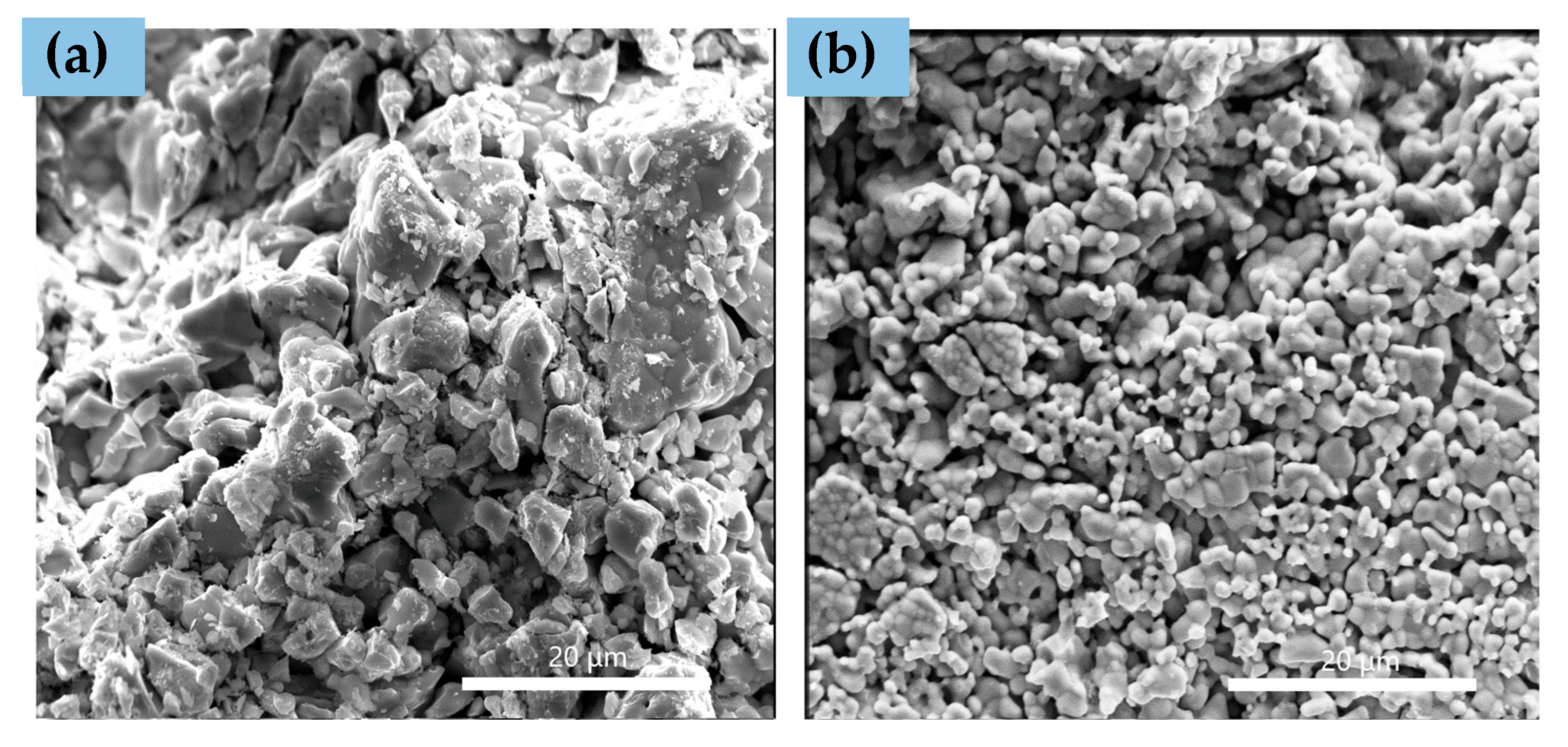
Cross-sectional SEM images of as-prepared pellets of all compounds before reduction and infiltration are presented in Figure 2.
The LSCCoT appears to form larger grain agglomerates than LSCNiT. The shape of these grains, visible in Figure 2a, is oblong with sharp edges, while those in Figure 2b are rounded. Furthermore, the LSCCoT structure shows significant differences in grains’ sizes, resulting in an uneven distribution. It is most likely that the cobalt dopant partially acted as a sintering aid, leading to the grains’ agglomeration and its sintering into bigger structures. However, both microstructures remained porous, which is essential for the further infiltration step that was planned in this experiment and a final exsolution to occur. Additionally, the porous structure is one of the key requirements that the anode material must meet.
After a detailed examination of the host materials, the infiltration process was conducted. The porous pellets were infiltrated with an iron nitrate solution and decomposed at 500 °C to obtain ca. 5%, 10%, and 15% gains in mass weight. The exact percentage increases in mass for particular samples is presented in Table 2.

3.2. After Infiltration and before Reduction in Dry H2

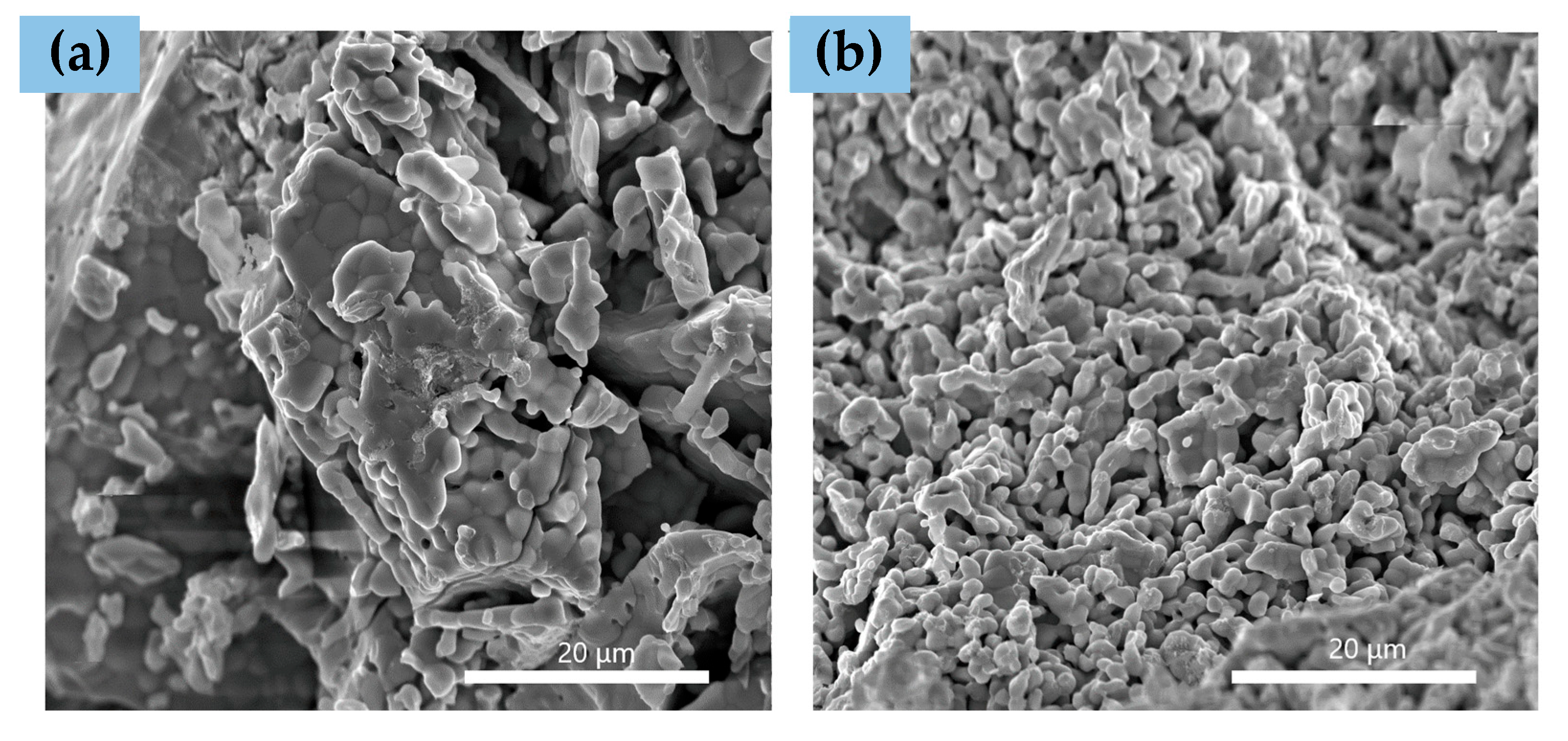
Figure 3 shows cross-sectional SEM images of LSCCoT and LSCNiT microstructures with a 15% gain in mass weight.
SEM images do not indicate major visible differences between infiltrated and not infiltrated (Figure 2) compounds, which suggests that iron nitrate solution is an excellent precursor, and even after decomposing to an iron oxide form, it does not create any non-uniformity in the modified structure. Moreover, the structure of the examined compounds remained porous, and the shape of the grains in the LSCCoT material slightly changed from sharp to more rounded. However, it should be noted that the images could have been taken at different orientations. Additionally, the presented figures are not surface images but cross-sections of the materials, suggesting that infiltration was indeed successful and the iron nitrate solution was implemented inside the structure. This phenomenon will most certainly favor forcing a further exsolution process in all the pellets. Following that, the compounds used in the described proportions were selected correctly, and the soaking process did not destroy the samples’ material. Therefore, using β-cyclodextrin as a viscosity-increasing additive was an appropriate choice, and β-cyclodextrin is worth using for similar types of infiltrations.

3.3. After Infiltration and Reduction in Dry H2–Topotactic Ion Exchange Exsolution

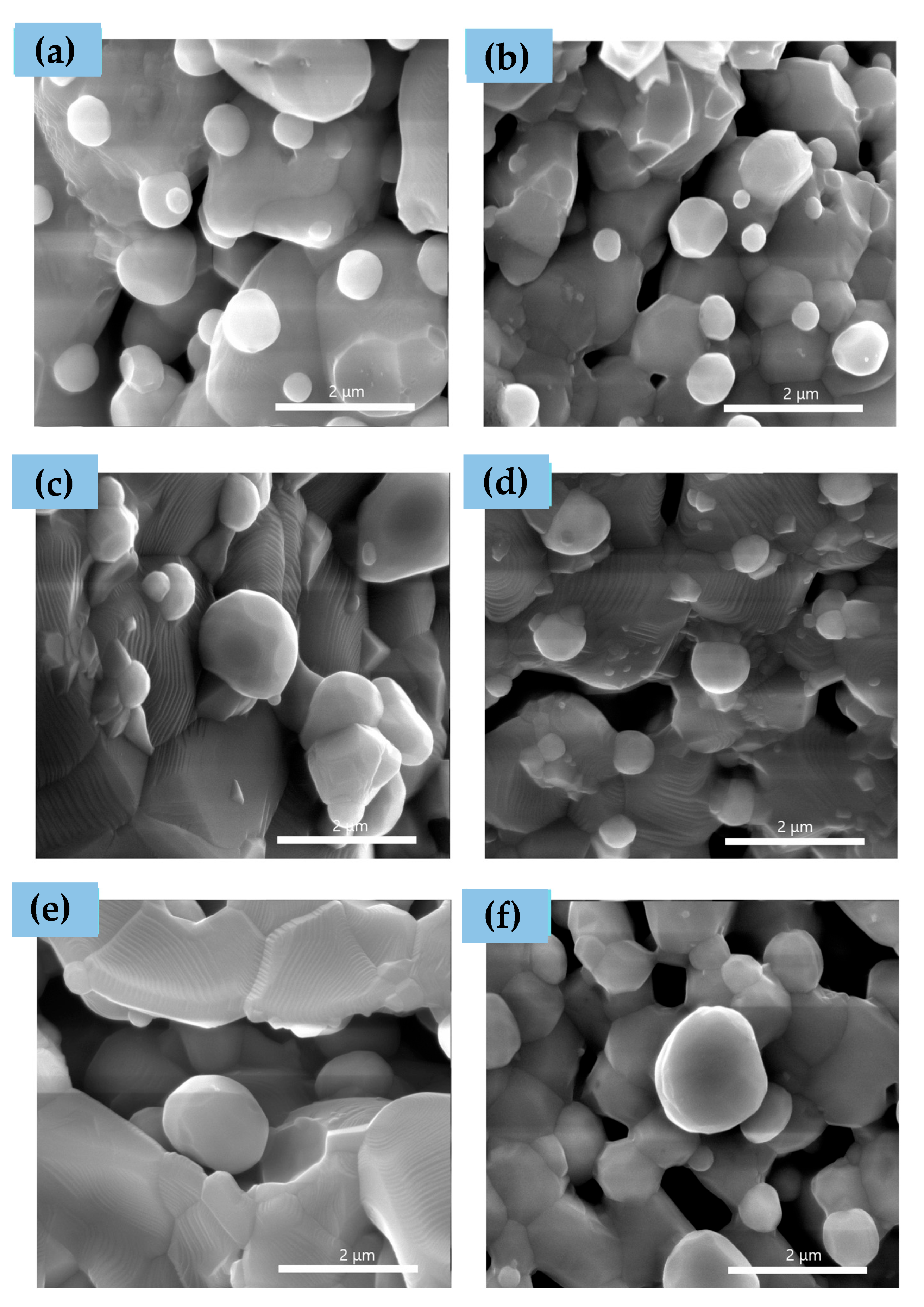
Cross-sectional SEM images of LSCCoT and LSCNiT infiltrated with 5%, 10%, and 15% gains in mass weight after reduction in H2 are shown in Figure 4.
The particles formed after topotactic ion exchange exsolution, presented in Figure 4a,b, seem to have similar sizes and round shapes. Nonetheless, the particles are not uniform, which suggests different conditions, such as the amount of accessible iron or host grains’ microstructure favoring the exsolution process in particular areas. The size of particles also indicates the reduction temperature being too high, leading the topotactic ion exchange to repeat and the formed particles to agglomerate. Additionally, partial particle anchoring can be observed as the theory of exsolution predicts. Figure 4e,f show that the infiltration leading to a gain of 15% mass weight have greater impact on microstructures. In the case of LSCCoT + 15%, there are only a few visible particles, and the microstructure appears to be less porous than LSCNiT + 15%. However, the number of particles in Figure 4f is not as great as those with 5% and 10% mass weight increases. The largest deviations in microstructures are visible in Figure 4c,d. Both compounds have a 10% gain in mass weight. The SEM image of LSCCoT + 10% shows changes in particle sizes as well as its quantity. LSCNiT + 10%, on the other hand, exhibits almost no changes in comparison to LSCNiT + 5%. It should be noted that exsolved particles are not nanometric, which was intended in order to conduct elemental analysis. However, this procedure allows us to have greater insight into how conditions of the reduction process, such as higher temperature, impact the exsolution process itself.
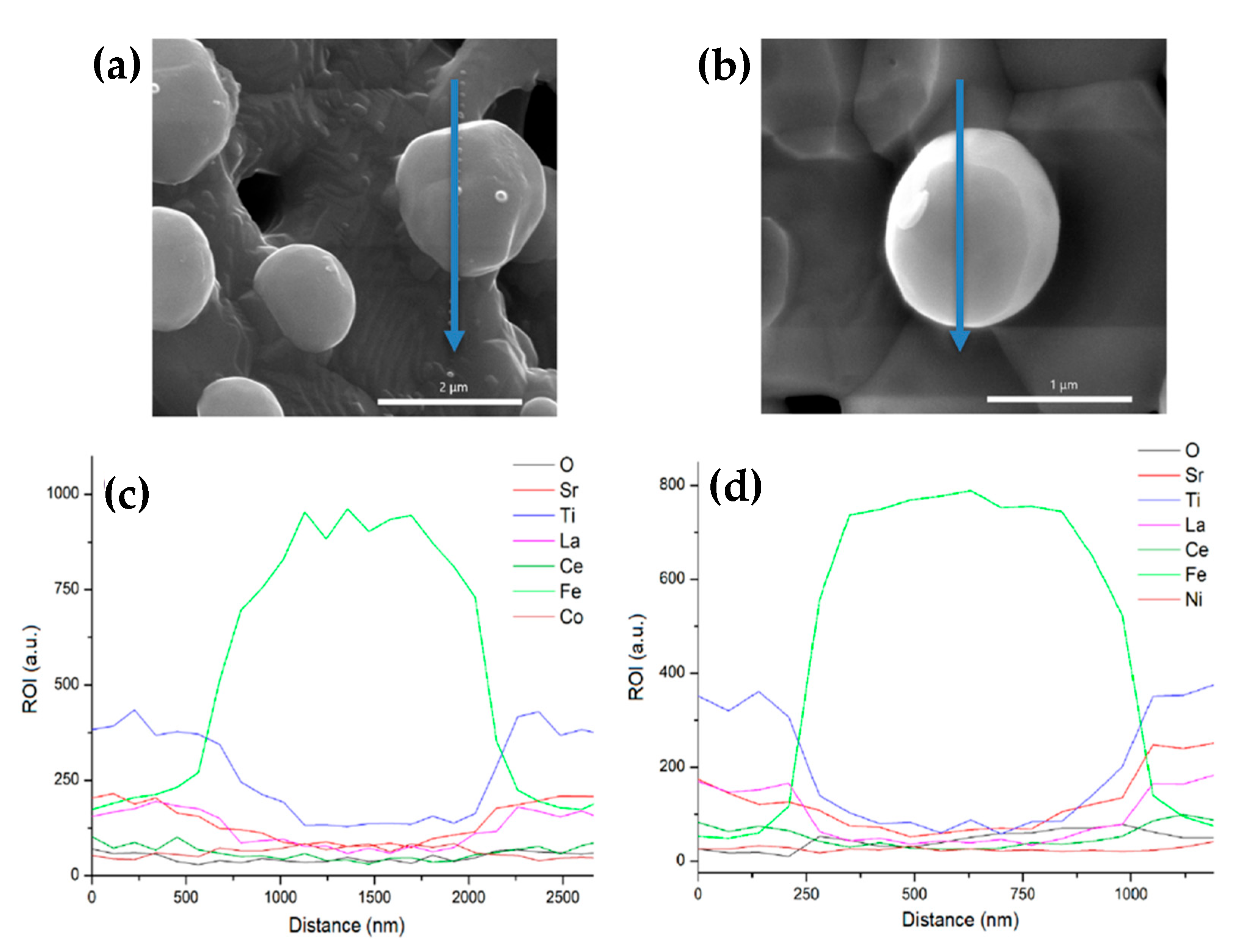
Results of a linear EDS analysis over large particles formed during the topotactic ion exchange exsolution are presented in Figure 5, as well as SEM images of inspected areas.
The linear EDS scans shows that particles (a) and (b) are enriched in iron, which proves that the infiltration was successful. EDS scans also show that the contents of Ti, Sr, La, and Ce decrease as the scan approaches the particle. On the other hand, the contents of Co and Ni are maintained at the same level, which suggests their presence inside the particle. Although the scan clearly shows greater amounts of iron, on this basis, we suspect the formation of bimetallic alloys, which corresponds to the XRD patterns presented in Figure 6. However, it should be noted that due to the large penetration depth with the EDS technique, the examined signals could also come from the host material and not the particle itself.
The XRD patterns after reduction show that besides a SrTiO3-like phase, there are some peaks at 2θ = 44.66, 65.20, 82.54, and 2θ = 44.72, 65.06, 82.47, which can be identified as Fe0.94Ni0.06 and Co3Fe7 compounds. Taking also into account a previous EDS analysis, this observation may confirm the formation of bimetallic alloys on the surfaces of the grains. However, the authors are aware that the XRD patterns of these compounds are quite similar to that of Fe (JCPDS 06-0696). Moreover, the formed particles are significantly enriched with iron, which may affect the obtained results. An unambiguous verification of the possible formation of bimetallic structures may be conducted using the TEM/EDS technique.
Nevertheless, the XRD patterns for both samples are alike. The signals for both samples occur at similar angles, which proves that LSCCoT and LSCNiT crystalize with the same structure, and thus, the signals come from the same crystallographic planes. Moreover, these compounds are stable in both reducing conditions and at high temperatures, confirming their usefulness in SOFC anodes.

4. Conclusions

In this work, the possibility of forming Co-Fe and Ni-Fe bimetallic alloys on SrTiO3-based host material via exsolution with topotactic ion exchange is confirmed. The conducted research proves that synthesized materials have great potential as novel materials for SOFC anodes. The particles are socketed in the host material, which can prevent carbon deposition and therefore improve the lifespan of a catalytic system. High temperature reduction was chosen intentionally to force the growth of forming particles; however, in order to meet every expectation, it is important to exsolve the particles in nanometric sizes. This can be achieved by lowering the temperature at which the material is reduced in an H2 atmosphere. Further research will focus on the material’s application as an anode in a working SOFC and the examination of their properties.

Author Contributions

Conceptualization, B.B. and K.K.; methodology, B.B.; software, K.K.; formal analysis, K.K. and W.K.; investigation, K.K. and W.K.; writing—original draft preparation, K.K.; writing—review and editing, B.B.; visualization, K.K.; supervision, B.B.; project administration, B.B. All authors have read and agreed to the published version of the manuscript.

Funding

The research project was supported by the National Science Center under grant No. NCN 2021/42/E/ST5/00450.

Data Availability Statement

Data are contained within the article.

Conflicts of Interest

The authors declare no conflicts of interest.

References

  1. Arshad, M.S.; Mbianda, X.Y.; Ali, I.; Wanbing, G.; Kamal, K.; Kauhaniemi, K.; Hassan, S.Z.; Yasin, G. Advances and Perspectives on Solid Oxide Fuel Cells: From Nanotechnology to Power Electronics Devices. Energy Technol. 2023, 11, 2300452. [Google Scholar] [CrossRef]
  2. Hanif, M.B.; Motola, M.; Gayyum, S.; Rauf, S.; Khalid, A.; Li, C.-J.; Li, C.-X. Recent advancements, doping strategies and the future perspective of perovskite-based solid oxide fuel cells for energy conversion. Chem. Eng. J. 2022, 428, 132603. [Google Scholar] [CrossRef]
  3. Fan, L.; Zhu, B.; Su, P.-C.; He, C. Nanomaterials and technologies for low temperature solid oxide fuel cells: Recent advances, challenges and opportunities. Nano Energy 2018, 45, 148–176. [Google Scholar] [CrossRef]
  4. Bianchi, F.R.; Padinjarethil, A.K.; Hagen, A.; Bosio, B. Multiscale analysis of Ni-YSZ and Ni-CGO anode based SOFC degradation: From local microstructural variation to cell electrochemical performance. Electrochim. Acta 2023, 460, 142589. [Google Scholar] [CrossRef]
  5. Shu, L.; Sunarso, J.; Hashim, S.S.; Mao, J.; Zhou, W.; Liang, F. Advanced perovskite anodes for solid oxide fuel cells: A review. Int. J. Hydrogen Energy 2019, 44, 31275–31304. [Google Scholar] [CrossRef]
  6. Singh, S.; Pandey, R.; Presto, S.; Carpanese, M.P.; Barbucci, A.; Viviani, M.; Singh, P. Suitability of Sm3+-Substituted SrTiO3 as Anode Materials for Solid Oxide Fuel Cells: A Correlation between Structural and Electrical Properties. Energies 2019, 12, 4042. [Google Scholar] [CrossRef]
  7. Vasyliv, B.D.; Podhurska, V.Y.; Ostash, O.P.; Vira, V.V. Effect of a Hydrogen Sulfide-Containing Atmosphere on the Physical and Mechanical Properties of Solid Oxide Fuel Cell Materials. In Nanochemistry, Biotechnology, Nanomaterials, and Their Applications, Proceedings of the 5th International Conference Nanotechnology and Nanomaterials (NANO2017), Chernivtsi, Ukraine, 23–26 August 2017; Fesenko, O., Yatsenko, L., Eds.; Springer Proceedings in Physics; Springer: Cham, Switzerland, 2018; pp. 475–485. [Google Scholar]
  8. Gao, Y.; Chen, D.; Saccoccio; Lu, Z.; Ciucci, F. From Material Design to Mechanism study: Nanoscale Ni Exsolution on a Highly Active A-site Deficient Anode Material for Solid Oxide Fuel Cells. Nano Energy 2016, 27, 499–508. [Google Scholar] [CrossRef]
  9. Peng, J.; Zhao, D.; Xu, Y.; Wu, X.; Li, X. Comprehensive Analysis of Solid Oxide Fuel Cell Performance Degradation Mechanism, Prediction, and Optimization Studies. Energies 2023, 16, 788. [Google Scholar] [CrossRef]
  10. Mo, B.; Rix, J.; Pal, U.; Basu, S.; Gopalan, S. Improving SOFC Anode Electrocatalytic Activity Using Nanoparticle Infiltration into MIEC Compositions. J. Electrochem. Soc. 2020, 167, 134506. [Google Scholar] [CrossRef]
  11. Kim, J.H.; Kim, J.K.; Liu, J.; Curcio, A.; Jang, J.S.; Kim, I.D.; Ciucci, F.; Jung, W. Nanoparticle Ex-solution for Supported Catalysts: Materials Design, Mechanism and Future Perspectives. ACS Nano 2021, 15, 81–110. [Google Scholar] [CrossRef]
  12. Neagu, D.; Oh, T.-S.; Miller, D.N.; Menard, H.; Bukhari, S.M.; Gamble, S.R.; Gorte, R.J.; Vohs, J.M.; Irvine, J.T.S. Nano-socketed nickel particles with enhanced coking resistance grown in situ by redox exsolution. Nat. Commun. 2015, 6, 8120. [Google Scholar] [CrossRef]
  13. Abdalla, A.M.; Hossain, S.; Azad, A.T.; Petra, P.M.I.; Begum, F.; Eriksson, S.G.; Azad, A.K. Nanomaterials for solid oxide fuel cells: A review. Renew. Sustain. Energy Rev. 2018, 82, 353–368. [Google Scholar] [CrossRef]
  14. Lin, Y.; Fang, S.; Su, D.; Brinkman, K.S.; Chen, F. Enhancing grain boundary ionic conductivity in mixed ionic-electronic conductors. Nat. Commun. 2015, 6, 6824. [Google Scholar] [CrossRef]
  15. Hussain, S.; Yangping, L. Review of solid oxide fuel cell materials: Cathode, anode, and electrolyte. Energy Transit. 2020, 4, 113–126. [Google Scholar] [CrossRef]
  16. Liu, M.; Lynch, M.E.; Blinn, K.; Alamgir, F.M.; Yong, M.C. Rational SOFC material design: New advances and tools. Mater. Today 2011, 14, 534–546. [Google Scholar] [CrossRef]
  17. Kan, W.H.; Samson, A.J.; Thangadurai, V. Trends in electrode development for next generation solid oxide fuel cells. J. Mater. Chem. A 2016, 4, 17913–17932. [Google Scholar] [CrossRef]
  18. Joo, S.; Kwon, O.; Kim, K.; Kim, S.; Kim, H.; Shin, J.; Jeong, H.Y.; Sengodan, S.; Han, J.W.; Kim, G. Cation-swapped homogeneous nanoparticles in perovskite oxides for high power density. Nat. Commun. 2019, 10, 697. [Google Scholar] [CrossRef]
  19. Kwon, O.; Joo, S.; Choi, S.; Sengodan, S.; Kim, G. Review on exsolution and its driving forces in perovskites. J. Phys. Energy 2020, 2, 032001. [Google Scholar] [CrossRef]
  20. Kim, Y.H.; Jeong, H.; Won, B.R.; Jeon, H.; Park, C.H.; Park, D.; Kim, Y.; Lee, S.; Myung, J.H. Nanoparticle Exsolution on Perovskite Oxides: Insights into Mechanism, Characteristics and Novel Strategies. Nano-Micro Lett. 2024, 16, 33. [Google Scholar] [CrossRef]
  21. Joo, S.; Seong, A.; Kwon, O.; Kim, K.; Lee, J.H.; Gorte, R.J.; Vohs, J.M.; Han, J.W.; Kim, G. Highly active dry methane reforming catalysts with boosted in situ grown Ni-Fe nanoparticles on perovskite via atomic layer deposition. Sci. Adv. 2020, 6, eabb1573. [Google Scholar] [CrossRef]
  22. Sun, Y.; Zhou, X.; Zeng, Y.; Amirkhiz, B.S.; Wang, M.; Zhang, L.; Hua, B.; Li, J.; Li, J.; Luo, J. An ingenious Ni/Ce co-doped titanate based perovskite as a coking-tolerant anode material for direct hydrocarbon solid oxide fuel cells. J. Mater. Chem. A 2015, 3, 22830–22838. [Google Scholar] [CrossRef]
  23. Huízar-Félix, A.M.; Hernández, T.; de la Parra, S.; Ibarra, J.; Kharisov, B. Sol–gel based Pechini method synthesis and characterization of Sm1−x CaxFeO3 perovskite 0.1≤x≤0.5. Powder Technol. 2012, 229, 290–293. [Google Scholar] [CrossRef]
  24. Dimesso, L. Pechini Processes: An Alternate Approach of the Sol–Gel Method, Preparation, Properties, and Applications. In Handbook of Sol-Gel Science and Technology; Klein, L., Aparicio, M., Jitianu, A., Eds.; Springer: Cham, Switzerland, 2018; pp. 1067–1088. [Google Scholar]
  25. Sunde, T.O.L.; Grande, T.; Einarsrud, M.-A. Modified Pechini Synthesis of Oxide Powders and Thin Films. In Handbook of Sol-Gel Science and Technology; Klein, L., Aparicio, M., Jitianu, A., Eds.; Springer: Cham, Switzerland, 2018; pp. 1089–1118. [Google Scholar]
  26. Crystallography Open Database. Available online: https://www.crystallography.net/cod/1512124.html (accessed on 10 April 2024).
  27. Database of Ionic Radii. Available online: https://abulafia.mt.ic.ac.uk/shannon/ptable.php (accessed on 10 April 2024).
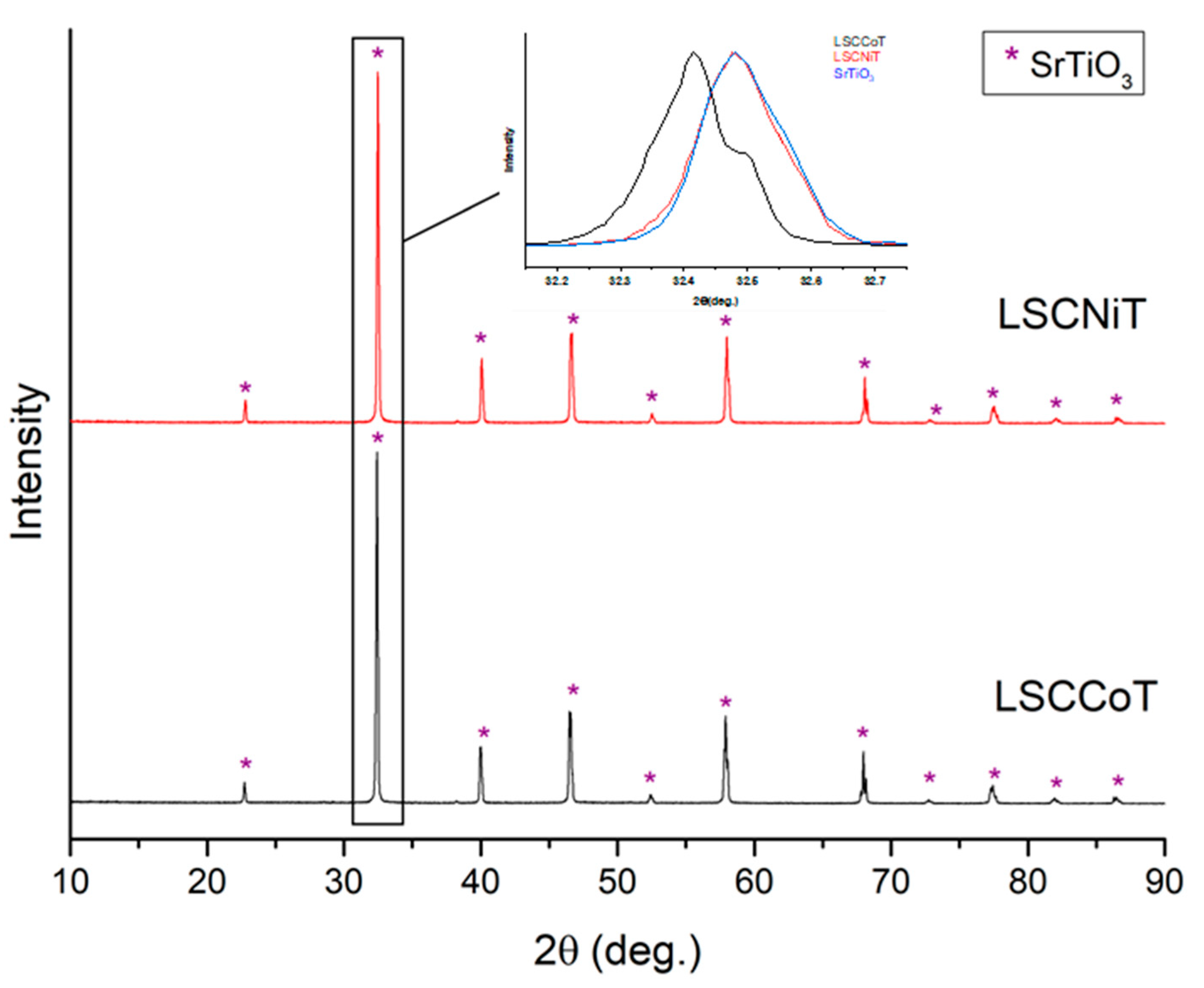
Figure 1. XRD patterns of as-prepared LSCNiT and LSCCoT powders. The inset shows a magnification of the main peaks compared for both LSCNiT and LSCCoT and a reference SrTiO3 pattern.
Fuels 05 00031 g001
Figure 2. Cross-sectional SEM images of fracture surfaces of the as-prepared pellets of (a) LSCCoT and (b) LSCNiT before infiltration and reduction.
Fuels 05 00031 g002
Figure 3. Cross-sectional SEM images of fracture structures of infiltrated (a) LSCCoT + 15% and (b) LSCNiT + 15%.
Fuels 05 00031 g003
Figure 4. Cross-sectional SEM images of fracture structures of infiltrated compounds: (a) LSCCoT + 5%, (b) LSCNiT + 5%, (c) LSCCoT + 10%, (d) LSCNiT + 10%, (e) LSCCoT + 15%, (f) LSCNiT + 15%.
Fuels 05 00031 g004
Figure 5. SEM images of inspected area of (a) LSCCoT with 15% gain in mass weight and (b) LSCNiT with 15% in mass increase after infiltration with iron precursor and reduction at 1200 °C in H2. The blue arrows indicate location and direction of linear EDS scans, and scan results are shown in (c) LSCCoT and (d) LSCNiT, respectively.
Fuels 05 00031 g005
Figure 6. XRD patterns of LSCNiT + 15% and LSCCoT + 15% after infiltration with iron precursor and reduction at 1200 °C in dry H2.
Fuels 05 00031 g006
Table 1. Ionic radius of elements for 12-fold coordination of La, Ce, and Sr and 6-fold coordination for Ti, Ni, and Co [27].
ElementIonic Radius [Å]
La3+1.36
Ce4+1.14
Ni4+0.48
Co4+0.53
Sr2+1.44
Ti4+0.605
Table 2. Mass percentage increases in LSCCoT and LSCNiT obtained by infiltration with iron nitrate solution.
CompoundSample +5%Sample +10%Sample +15%
LSCCoT5.37%10.24%15.04%
LSCNiT5.60%10.56%15.08%
Disclaimer/Publisher’s Note: The statements, opinions and data contained in all publications are solely those of the individual author(s) and contributor(s) and not of MDPI and/or the editor(s). MDPI and/or the editor(s) disclaim responsibility for any injury to people or property resulting from any ideas, methods, instructions or products referred to in the content.