Article

Process Engineering of the Acetone-Ethanol-Butanol (ABE) Fermentation in a Linear and Feedback Loop Cascade of Continuous Stirred Tank Reactors: Experiments, Modeling and Optimization

Department of Bioprocess Engineering, Beuth University of Applied Sciences Berlin, Seestraße 64, 13347 Berlin, Germany
*
Author to whom correspondence should be addressed.
Fuels 2021, 2(2), 108-129; https://doi.org/10.3390/fuels2020007
Submission received: 24 January 2021 / Revised: 13 February 2021 / Accepted: 20 February 2021 / Published: 1 April 2021
(This article belongs to the Special Issue Biomass Conversion to Biofuels)

Abstract

:
The production of butanol, acetone and ethanol by Clostridium acetobutylicum is a biphasic fermentation process. In the first phase the carbohydrate substrate is metabolized to acetic and butyric acid, in the following second phase the product spectrum is shifted towards the economically interesting solvents. Here we present a cascade of six continuous stirred tank reactors (CCSTR), which allows performing the time dependent metabolic phases of an acetone-butanol-ethanol (ABE) batch fermentation in a spatial domain. Experimental data of steady states under four operating conditions—with variations of the pH in the first bioreactor between 4.3 and 5.6 as well as the total dilution rate between 0.042 h−1 and 0.092 h−1—were used to optimize and validate a corresponding mathematical model. Beyond a residence time distribution representation and substrate, biomass and product kinetics this model also includes the differentiation of cells between the metabolic states. Model simulations predict a final product concentration of 8.2 g butanol L−1 and a productivity of 0.75 g butanol L−1 h−1 in the CCSTR operated at pHbr1 of 4.3 and D = 0.092 h−1, while 31% of the cells are differentiated to the solventogenic state. Aiming at an enrichment of solvent-producing cells, a feedback loop was introduced into the cascade, sending cells from a later state of the process (bioreactor 4) back to an early stage of the process (bioreactor 2). In agreement with the experimental observations, the model accurately predicted an increase in butanol formation rate in bioreactor stages 2 and 3, resulting in an overall butanol productivity of 0.76 g L−1 h−1 for the feedback loop cascade. The here presented CCSTR and the validated model will serve to investigate further ABE fermentation strategies for a controlled metabolic switch.

1. Introduction

The acetone-butanol-ethanol (ABE) process is the production of the eponymous solvents by fermentation with solvent-forming Clostridia. In 1862 Louis Pasteur discovered motile, rod-shaped bacteria to produce butanol under anaerobic conditions [1,2]. In 1915, Chaim Weizmann established an industrial process for the biotechnological production of acetone (and butanol), which was used all around the world in the following decades before being replaced by a synthesis of these solvents from mineral oil [3,4]. Nowadays, we await a comeback of the industrial ABE process as not only the demand for sustainable produced solvents and bulk chemicals is increasing, but butanol is further discussed as a promising biofuel. Beside the exploration of new non-food and inexpensive waste materials as substrates for the fermentation process [5,6], an important setscrew to improve the economics of the process is the development of new fermentation technologies [7,8]. These should allow effective raw material conversion with a high yield, accelerate the onset of solvent formation in a biphasic ABE process and stabilize the bacteria in this metabolic phase. While in the first phase of the ABE fermentation, called acidogenesis, acetic and butyric acid are the main fermentation products, the formation of butanol, acetone and ethanol under partial re-assimilation of the organic acids occurs in the second phase, called solventogenesis. The research of the past decades has shown that low pH and/or the high concentration of the undissociated organic acids trigger the metabolic switch from acidogenesis to solventogenesis [9,10]. Investigations with external electron donors, such as methyl viologen or neutral red, have further shown that the redox state of the cells influences the bias for acidogenesis and solventogenesis, respectively [11,12,13]. Moreover, it has been proposed that small concentrations of butanol might promote the metabolic shift [14]. Clostridium acetobutylicum was used as a model organism in the majority of the studies investigating the metabolic switch. However, under certain conditions C. acetobutylicum as well as other clostridial species fails to switch its metabolism to the solventogenic state, resulting in a hyper-acidification of the fermentation broth (pH ≤ 3.8) and a complete arrest of metabolic activity. The molecular mechanism behind this phenomenon often described as “acid crash” is still open. In some cases the spontaneous loss of the mega-plasmid pSOL1, encoding genes essential for solvent production, is a sound explanation. However, how this event can occur repeatedly under certain conditions, i.e., low buffer concentrations, while it rarely occurs under other conditions, i.e., high buffer concentrations, remains to be clarified. Explaining and controlling the metabolic shift has been the aim of numerous studies in the past [15]. In batch-experiments, controlling the pH at 4.5 to 5.0 has been described as a successful strategy for a stable solventogenic phase achieving high butanol concentrations [10]. However, onset of solvent formation is observed not earlier than 15 h after start of fermentation under such conditions. The maximal product concentrations are only reached after about 36 h [10,16], which limits the productivity of the batch fermentation processes. Additions of acetate and butyrate have been shown to increase the productivity of batch processes [17]. However, determining the optimal fermentation phase for acetate (or butyrate) co-feeding is challenging and laborious in a batch process as precise reproducibility of the time profile is limited. We here developed a model system that captures the metabolic phases of the ABE fermentation in different stages of a continuously operated bioreactor cascade at steady state. On the one hand this system allows analyzing the physiological characteristics of cells in the different metabolic phases, including the otherwise only transient occurring phases. On the other hand we aim at accelerating the solvent production and hence increasing the productivity of the fermentation process by varying the operating conditions of the cascade. In order to reduce the experimental work for this second task, we started developing a mathematical model that describes the continuous, multi-stage ABE fermentation process taking into account the presence of different subpopulation types in each bioreactor tank. Using experimental data from four operating conditions of the linear cascade, the unknown kinetic parameters of the model were estimated and the predictive capacity of the steady state simulations was validated. To further validate the model and to test a potential strategy for faster solvent formation, the simulator as well as the experimental set-up was modified by introducing a feedback loop from bioreactor 4 to bioreactor 2 of the cascade. In that way the fermentation broth with solventogenic cells and a higher butanol concentration is introduced into an early phase of the ABE process.

2. Materials and Methods

2.1. Microorganism and Medium

The strain used in this study was Clostridium acetobutylicum DSM 792 obtained from the DSMZ Germany. All fermentations were started from cryo-preserved spore aliquots, which were exposed to a 10 min heat shock at 75 °C directly before germination. First pre-cultures were cultivated in Clostridia Growth Medium (CGM) [18] at a scale of 50 mL in a 500 mL bottle with a gas outlet. After 20 to 40 h incubation at 37 °C, 5 mL of this first pre-culture were used to set-up a second pre-culture in the scale of 50 mL containing 25 g L−1 glucose, 1 g L−1 KH2PO4, 5 g L−1 yeast extract, 0.2 g L−1 MgSO4·7H2O, 0.01 g L−1 FeSO4·7H2O and 0.01 g L−1 MnSO4·H2O. The medium was adjusted to pH 6.9. After incubation for 13 h at 37 °C, the second pre-culture was used to start a batch fermentation with a total volume of 0.45 L in the first bioreactor of the cascade (Figure 1). The medium for the batch fermentation was the same as in the second pre-culture except for a lower level of glucose of about 5 g L−1 and a pH of 5.6. The cultivation temperature in the cascade was controlled at 32 °C during the entire process. The phosphate-limited feed medium of the continuous process contained 60 g L−1 glucose, 0.1 g L−1 KH2PO4, 5 g L−1 yeast extract, 0.2 g L−1 MgSO4·7H2O, 0.01 g L−1 FeSO4·7H2O and 0.01 g L−1 MnSO4·H2O. To prevent contamination, the medium in the feed bottle was adjusted to pH 2.5 with 32% HCl prior to autoclaving. During the process the pH was adjusted with sterile 1.5 M KOH. The feed medium was further supplemented with 0.1% (v/v) Polypropylene glycol P2000 (Merck KGaA, Darmstadt, Germany) to prevent foam formation in the cascade. All media were gassed with nitrogen for at least 1 h to ensure anaerobic conditions. In the cascade the fermentation broth was pressurized with nitrogen during the entire process.

2.2. Continuous Fermentation in a Six-Stage Bioreactor Cascade

For observation of physiological characteristics in different metabolic phases along the continuous bioreactor cascade, design and steady-state operation of the cascade must satisfy several conditions:
-
Residence time distribution approximates plug flow behavior, minimizing backmixing.
-
Total residence time is in the order of the duration of a batch fermentation (up to 36 h [16]).
-
Residence time in single reactors allows for resolution of temporal separation of metabolic phases (minimum duration of a metabolic phase approximately 6 h [16]).
The simplest design of the continuous bioreactor cascade therefore consists of six linearly coupled stirred tanks (Figure 1A), allowing for additional modifications of the configuration such as feedback loops (Figure 1B).
For starting the process, a batch fermentation in the first bioreactor was performed until the biomass had reached an OD600 of 2, then the system was switched to the continuous mode with a feeding rate of 0.1 or 0.22 L h−1 (Table 1). Now being in continuous mode, the liquid volume in the first bioreactor was controlled at 0.4 L and bioreactor stages 2 to 6 were subsequently filled with fermentation broth (0.4 L each) within 9 h or 20 h, depending on the feeding rate. By daily sampling we monitored the establishment of a steady state throughout the cascade of continuously stirred tank reactors (CCSTR) (see Supplementary Figure S1a). When detecting constant metabolite and cell concentrations for at least three residence times, corresponding to 33 h and 72 h at the given feeding rates (compare Table 1), one of the operating parameters—the setpoint pH value in the first bioreactor pHbr1 or the feeding rate Fin—was modified. After an adaption period of three residences times, sampling of the new steady state was started. For the configuration with feedback loop (Figure 1B), fermentation broth of bioreactor 4 was pumped to bioreactor 2 with a rate Fback of 0.055 L h−1. In total we performed six fermentations lasting up to 43 days. Mean and standard deviations of the steady state concentrations along the cascade were summarized in Table S2a.

2.3. Analytical Procedures

Acids (Acetic acid, butyric acid) and solvents (Ethanol, acetone, butanol) were analyzed with GC-FID (GC−14B, Shimadzu Inc., Kyoto, Japan) equipped with a ZB-FFAP column (Phenomenex Inc., Torrance, CA, USA). Glucose was measured with the Reflectoquant Glucose Test (Merck KGaA, Darmstadt, Germany). Optical density was obtained from a UV-VIS-spectrophotometer at a wave length of 600 nm. The cell dry mass was calculated from the OD600 using the experimentally determined factor of 0.4 g L−1 OD600−1 [6]. For monitoring the morphology of cells and sterile control, a microscope (Axiostar plus, Zeiss, Göttingen, Germany) with 100× magnification was used. Sporadically the phosphate concentrations were measured along the cascade using the phosphate analysis method DIN EN ISO6878 2004/09.

2.4. Mathematical Modeling Approach

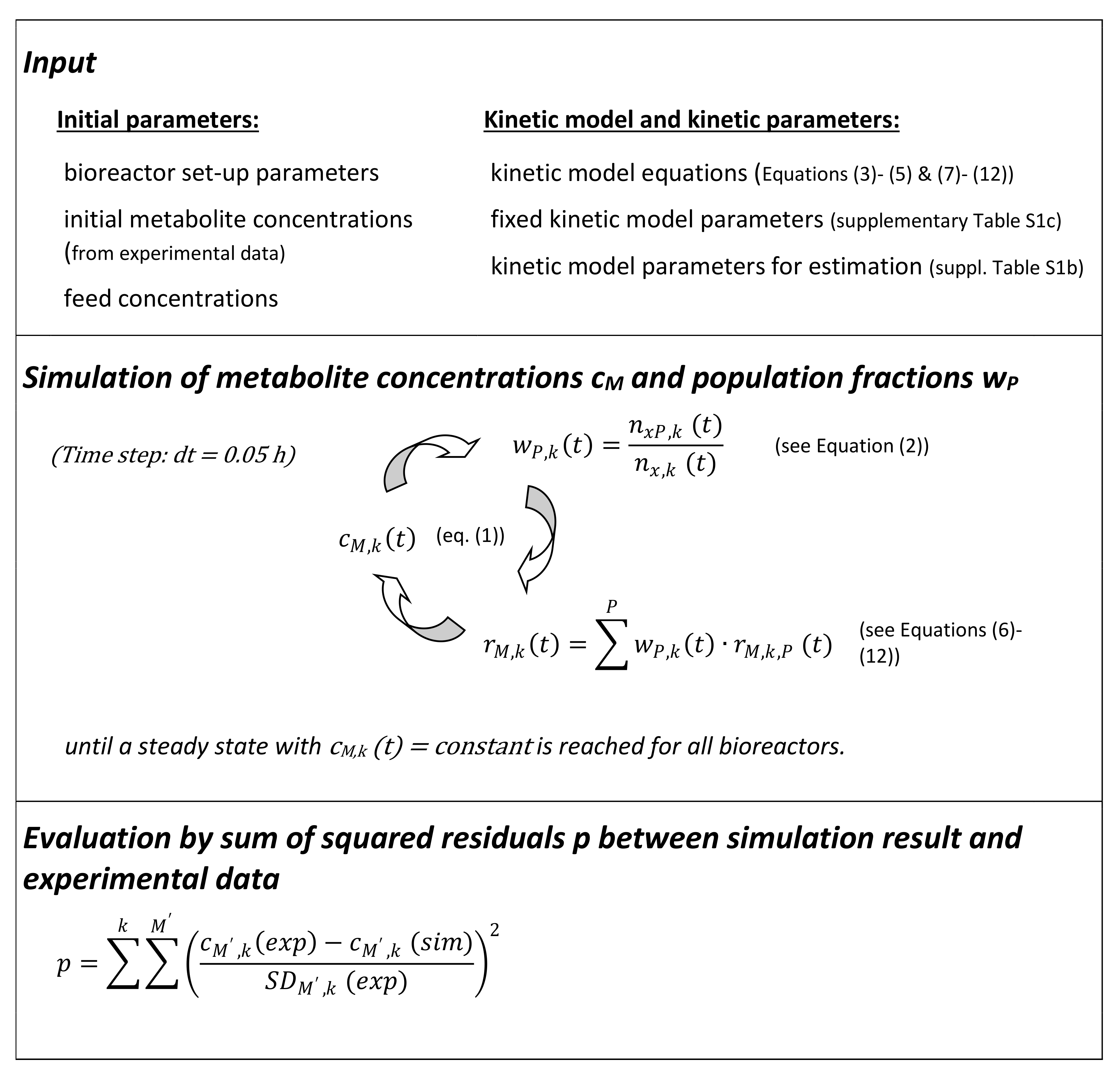
Developing an approach for computer simulations of the continuous, multi-stage ABE fermentation, we selected an unstructured segregated model [19]. Thus, while assuming empiric kinetic laws for the production and consumption of extracellular metabolites and cell growth without taking into consideration intracellular metabolites, we distinguished between three biomass subpopulations with individual metabolic properties, namely acidogenic (A), intermediate (I) and solventogenic (S) cells. A first version of the simulator, implemented by object-orientated programming in MATLAB R2011b, has been described [20]. The development of the metabolite concentrations in each bioreactor was simulated by iterative calculations of incremental changes of the metabolite concentrations in each bioreactor stage (Equation (1)), the development of the subpopulations (Equation (2)) and the specific metabolite conversion rates of the subpopulations and the total biomass depending on the present metabolite concentrations (Equations (6)–(12)) until a steady state is reached (Figure 2). A steady state was assumed when the concentrations of biomass (x), glucose (glu), ethanol (eth), acetone (act), butanol (but), acetic acid (aa), butyric acid (ba) and potassium dihydrogen phosphate (PO4) changed less than 0.01 g L−1 in each bioreactor stage for the residence time of one bioreactor stage Dbr1−1. In comparison to the earlier model [20], the following modifications were introduced: (I) Addition of a butanol- and glucose-dependent lysis term, accounting for subpopulation-independent cell lysis in the presence of high butanol concentrations and glucose limitation (see Equation (7)); (II) Allowing growth of intermediate and solventogenic cells in addition to growth in the acidogenic phase described before; (III) Flexibilizing the carbon balance by introducing the parameter sk, which accounts for possible additional carbon sources introduced by the yeast extract or the flux of carbon into additional products (see Equation (12)). The quality of the simulation result was evaluated by calculating the distance of the simulated steady state concentrations from experimentally observed metabolite concentrations as a weighted residual square sum over all metabolites (except for PO4) and all bioreactor stages, hereafter referred to as p (equation in Figure 2). The simulated steady state depends on several inputs, which have to be assigned before starting the simulation (Figure 2). The set-up parameters, i.e., the number of bioreactor, the culture volume in each bioreactor stage and the dilution rate in one bioreactor stage Dbr1, were the operating conditions in the experiment. The initial metabolite concentrations were taken from the experimental dataset (Data in Table S2a). The choice of initial values affected whether the simulation resulted in a suitable steady state or not, in the steady state itself, the corresponding metabolite concentrations were independent from the applied initial metabolite concentrations. During the simulations, the pH values along the cascade were set to the experimentally observed pH values. Modifications of the pH values in the bioreactor stages had an influence on the simulated steady state concentrations. The feed concentration for glucose and potassium dihydrogen phosphate were 60 g L−1 and 0.1 g L−1, respectively. The model equations for reaction kinetics are given below (Equations (3)–(5) and (7)–(12)). A part of the kinetic model parameters were set to fixed values derived from the literature, experimental investigations or estimations (Table S1c). The remaining kinetic model parameters (Table S1b) were estimated in a parameter optimization process described in the results section. The optimization was aimed at minimizing the p-value (equation in Figure 2). Table 2 gives an overview over all (fixed and optimized) kinetic parameters applied to obtain the simulation results presented in this work (Data in Table S2b).
The incremental changes of the metabolite concentrations over time in each bioreactor stage were calculated considering the in- and out-flux of the respective metabolite and its conversion by the present biomass (Equation (1), an overview of all variables and parameters of the model is given in Supplementary Table S1a–c):
c M , k   t + d t   =   c M , k   t + F i n V b r · c M , k 1   t F o u t V b r · c M , k   t +   r M , k   t · c x , k   t · d t
The changes in the size of a biomass-subpopulation in a bioreactor stage k were calculated on the basis of the in- and out-flux of respective cells, the growth of the respective subpopulation and the differentiation processes d (Equation (2)):
n x P , k t + d t   =   n x P , k t + ( F i n V b r · n x P , k 1 t F o u t V b r · n x P ,   k t +   r x ,   k , P t · n x P , k t   d 1   x P , k t · n x P t +   d 2   x P , k t · n x P , k t ) · d t
By Equations (3)–(5), the model describes differentiation from acidogenic to intermediate and from intermediate to solventogenic cells in dependence on the concentration of undissociated acetic and butyric acid. Reversal of differentiation was not considered. (Model parameters are distinguished by bold letters, values are given in Table 2).
c u n d i s s , k   t   =   c a a , k   t · 10 p H k 10 4.78 + 10 p H k + c b a , k   t · 10 p H k 10 4.86 + 10 p H k
d 1   x P , k t   =   m u _ d _   P · 1 1 +   e n _ i U D A _   P ·   K _ U D A _   P c u n d i s s , k   t
d 2   x P , k t   =   m u _ d _   P · 1 1 +   e n _ i U D A _   P ·   K _ U D A _   P c u n d i s s , k   t
The specific metabolite conversion rate of the total biomass in one bioreactor stage was calculated by Equation (6) as sum of the specific metabolite conversion rates of the individually sized subpopulations delivered by the kinetic model (contributing expressions see Equations (7)–(12)):
r M , k   t   =   P = A ; I ; S r M , k ,   P t · n x P , k t n x , k t
The following kinetic model Equations (7)–(12) for biomass evolution, product formation and substrate uptake have been assumed:
biomass evolution (=growth lysis)
r x , k ,   P t   =   m u _ m a x _ P · c P O 4 , k t c P O 4 , k t +   K s P O 4 · c g l u , k t c g l u , k t +   K s G L U · e n i B · K i B c b u t , k t 1 +   e n i B · K i B c b u t , k t   K d · c b u t , k   t · e n _ d G L U ·   K d G L U c g l u , k   t 1 +   e n _ d G L U ·   K d G L U c g l u , k   t
For the calculation of growth-dependent product formation and substrate consumption, only the growth-related part, but not the cell lysis-related part of the biomass evolution rate from Equation (7) was taken into consideration in Equation (8).
Biomass growth
r x , k ,   P t   =   m u _ m a x _   P · c P O 4 , k t c P O 4 , k t +   K s P O 4 · c g l u , k t c g l u , k t +   K s G L U · e n i B · K i B c b u t , k t 1 +   e n i B · K i B c b u t , k t
acid production and uptake (for MAcid = {aa; ba})
r M A c i d , k , P   t   =   r x , k , P   t · Y _ M x _ P + r _ M _ m a x _   P · c g l u , k   t c g l u , k   t +   K s G L U     k _ M _ u p _   P   · c g l u , k   t c g l u , k   t   +   K s G L U · c M , k   t c M , k   t   +   K s M
solvent production (for MSolv = {act; eth; but})
r M S o l v , k , P   t   =   r _ M _ m a x _   P · c g l u , k   t c g l u , k   t   +   K s G L U                                    
phosphate and glucose uptake
r P O 4 , k , P t   =   r x , k , P   t Y _ x p
r g l u , k ,     P   t   =   s k + r _ C O 2 _ P n _ C _ G L U · r x , k , P   t Y _ x s + M A c i d ,   M S o l v r x , k , P   t · Y _ M x _   P + r _ M _ m a x _   P · c g l u , k   t c g l u , k   t   +   K s G L U Y _ M s  
Model parameters in Table 2, presented in italics, were fixed to the given values according to literature information [20,21], experimental data or estimations (see also supplementary material Table S1c). All other parameters were retrieved from the parameter estimation process (see also Table S1b).

3. Results

3.1. Continuous Fermentations in a Linear CCSTR under Four Different Operating Conditions

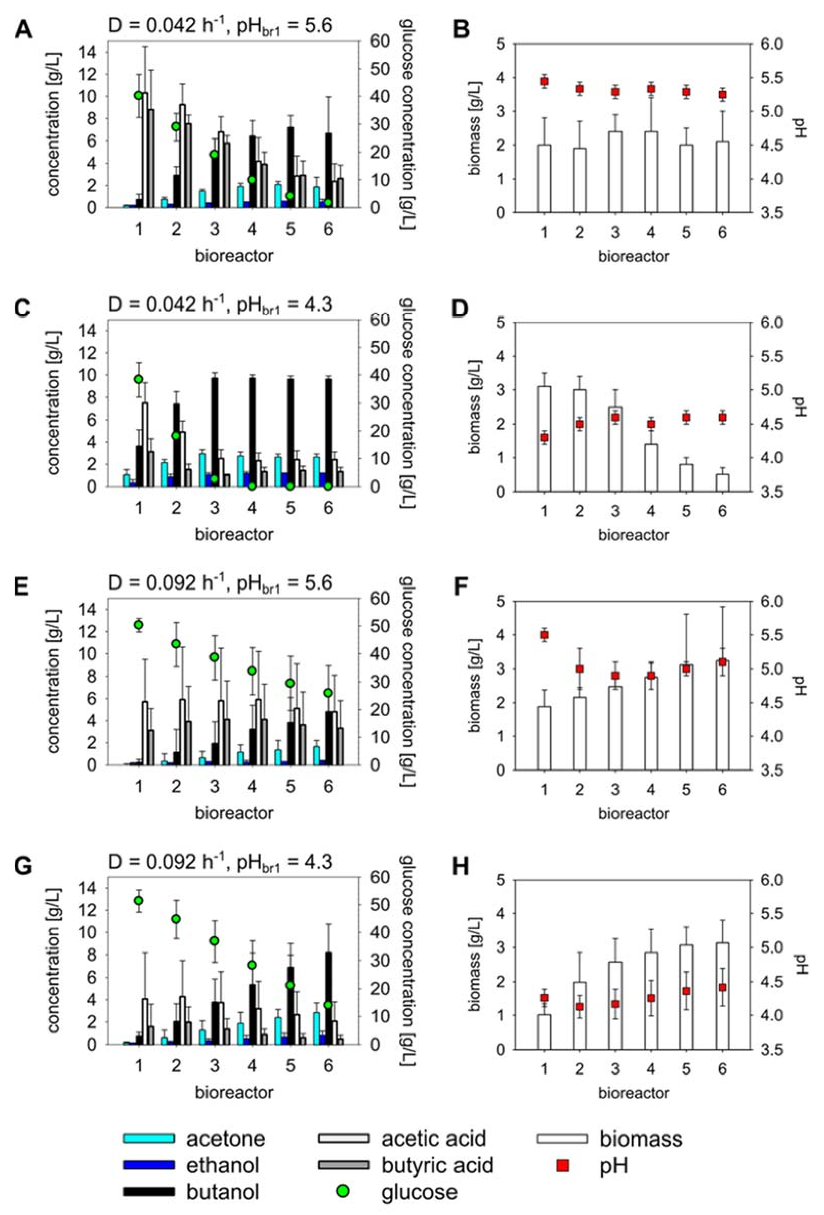
ABE fermentations have been investigated for many decades now. However no ideal operating conditions enabling high space-time yields and long-term stability of the process have been found yet. In order to analyze in which way the switch from acid-forming to solvent-forming cells can be accelerated, we established a Cascade of Continuous Stirred Tank Reactors (CCSTR). This bioreactor conformation with six reactors operated in series allows separating the different metabolic stages in a spatial manner. In the initial set-up, two operating parameters were investigated: the feeding rate Fin and the setpoint pH value in the first bioreactor of the cascade pHbr1 (see Figure 1A). Long-term continuous fermentations in the bioreactor cascade were performed in order to characterize steady states with constant metabolite concentrations in all bioreactor tanks under four different operating conditions. To this end, the feeding rate was set to 0.1 L h−1 (D = 0.042 h−1) and to 0.22 L h−1 (D = 0.092 h−1) and the pHbr1 was set to pH 5.6 and pH 4.3. The resulting four operating settings were repeatedly applied and the corresponding steady states were observed for periods corresponding to 3 to 18 residences times of the cascade (means of the reproduced steady states under the four operating conditions are shown in Figure 3; for an overview of the individually observed steady states see Table S2a).
Under all operating conditions we observed an accumulation of acetic and butyric acid in the first bioreactor stage (Figure 3A,C,E,G). In the following bioreactors the organic acids were then metabolized together with glucose, shifting the product spectrum towards the organic solvents—butanol, acetone and ethanol. These dominate the metabolite spectrum at the end of the cascade, though their yields depend on the operating conditions (Figure 3A,C,E,G). At a dilution rate of 0.042 h−1, corresponding to a residence time of 4 h per bioreactor, and a pHbr1 of 5.6, the acetic and butyric acid concentration in the first bioreactor reached 10.3 ± 4.2 g L−1 and 8.8 ± 3.6 g L−1, respectively (Figure 3A). Despite these high acid concentrations the biomass grew to a concentration of 2.0 ± 0.8 g L−1 and stayed on this level along the cascade (Figure 3B). The solvent concentrations are negligible in the first bioreactor, but increase from bioreactor 2 to 4. When the glucose concentration dropped below 5 g L−1 in bioreactor 5 and 6, the solvent formation stopped, yielding final concentrations of 6.7 ± 3.3 g L−1 butanol, 1.8 ± 0.9 g L−1 acetone and 0.4 ± 0.3 g L−1 ethanol (Figure 3A). Changing the pHbr1 to 4.3 while keeping the total dilution rate at 0.042 h−1 reduced the accumulation of acetic and butyric acid in the first bioreactor to 7.5 ± 1.8 g L−1 and 3.1 ± 1.2 g L−1, respectively (Figure 3C). At the same time, the formation of the solvents as well as consumption of the glucose over the cascade was increased. Thus maximal concentrations of butanol (9.7 ± 0.5 g L−1), acetone (2.9 ± 0.4 g L−1) and ethanol (1.0 ± 0.2 g L−1) were already reached in bioreactor 3, while glucose was nearly depleted at this point (Figure 3C). The glucose depletion was accompanied by a severe decrease of the biomass concentration from 3.0 ± 0.4 g L−1 in bioreactor 2 to 0.5 ± 0.2 g L−1 in bioreactor 6 (Figure 3D).
To get a better resolution of the metabolic processes in bioreactor 1 to 3 we increased the dilution date to 0.092 h−1 which corresponds to a residence time of 1 h 49 min per bioreactor. Again the pHbr1 was set to 5.6 (Figure 3E,F) and 4.3 (Figure 3G,H). Under both conditions the acetic acid and butyric acid concentrations rose in bioreactor 2 (and 3) and a net uptake of the organic acids only appeared in the later bioreactors of the cascade. Thus maximal organic acids concentrations were observed in bioreactor 3 and 4 at pHbr1 = 5.6 (Figure 3E, Table S2a) and in bioreactor 2 at pHbr1 = 4.3 (Figure 3G, Table S2a), respectively. The minima of the pH profiles coincide with the maxima of the acid concentrations (see Figure 3F,H). Despite of this discontinuous development of organic acids along the cascade there was a formation of solvents from bioreactor 1 to bioreactor 6 as well as a nearly linear uptake of glucose under both pHbr1 conditions (Figure 3E,G). At pHbr1 = 5.6 solvent formation and glucose uptake were slower than at a pHbr1 of 4.3 and resulted in concentrations of 4.8 ± 1.9 g L−1 butanol, 1.6 ± 0.6 g L−1 acetone, 0.3 ± 0.1 g L−1 ethanol and 25.9 ± 9.9 g L−1 glucose in bioreactor 6 (Figure 3E). This roughly corresponds to the composition of bioreactor 3 in the cascade operated at a dilution rate of 0.042 h−1 and a pHbr1 of 5.6 (Figure 3A, Table S2a). In the cascade operated at pHbr1 = 4.3 (and D = 0.092 h−1) butanol, acetone, ethanol and glucose reached final concentrations of 8.2 ± 2.6 g L−1, 2.8 ± 0.9 g L−1, 0.8 ± 0.4 g L−1 and 13.9 ± 8.3 g L−1, respectively (Figure 3G). These solvent concentrations were significantly lower than those observed in bioreactor 3 of the cascade operated at D = 0.042 h−1 and pHbr1 = 4.3 amounting to 9.7 ± 0.5 g L−1 butanol, 2.9 ± 0.4 g L−1 acetone and 1.0 ± 0.2 g L−1 ethanol (Figure 3C, Table S2a). However, the remaining glucose concentration of 13.9 ± 8.3 g L−1 in the final bioreactor of the process at D = 0.092 h−1 which is observed after a total mean residence time of 10.9 h is also much higher than the glucose concentration of 2.5 ± 3.4 g L−1 in bioreactor 3 of the process at D = 0.042 h−1 that is observed after a mean residence time of 12 h (3 × 4 h). These results indicate that process operating conditions were in a range, in which the fermentation time (residence time) is crucial for a complete transformation of the substrate to solvents.

3.2. Estimation and Validation of the Mathematical Model Parameters Based on the Experimental Data from the Linear Cascade

Experimental data from three of the four operating conditions (D = 0.042 h−1/pHbr1 = 5.6; D = 0.042 h−1/pHbr1 = 4.3; D = 0.092 h−1/pHbr1 = 4.3) were used for parameter estimation of the mathematical model described above (see Section 2.4. The fourth data set (D = 0.092 h−1/pHbr1 = 5.6) was reserved for model validation. In total 30 parameters were estimated within rationally predefined boundaries (Table 2, Table S1b). At the same time, the model included 25 fixed parameters, which had been derived from the literature, experimental studies or calculations (Table 2, Table S1c). As a starting point of the optimization process we used the parameter set that had been found by educated guessing to deliver reasonable simulation results for a first version of the mathematical model [20]. The parameter for the maximal butyric acid uptake rate of intermediate cells k_BA_up_ (I) was initially set to 0.25 corresponding to the center of the solution space (Table S1b). The parameter optimization was realized using the MATLAB function “fmincon” (with “active set algorithm”), which allows defining dependencies between the parameters. Here we used the restriction “mu_d_ (A) (differentiation rate of acidogenic to intermediate cells)” < “mu_d_ (I) (differentiation rate of intermediate to solventogenic cells)” to prevent accumulation of intermediate cells observed in first attempts of the parameter optimization without constraints. The estimation algorithm minimized the distance between the simulated and the experimentally observed metabolite (glucose, ethanol, acetone, butanol, acetic acid and butyric acid) and biomass concentrations in all six bioreactor stages of all three operating conditions. The differences between simulated and experimental values were weighted by the experimentally observed variances, which we defined as maximum of the standard deviations in the individual data sets, the standard deviation of the averaged data set and 0.1 (compare Table S2a—note §). Thus, the predictions of the model for the experimentally accurately determined solvent concentrations counted more for the quality of the respective parameter set than a good agreement of the model with data from the fluctuating measurements of organic acid concentrations. Furthermore, the discrepancy of a mismatch of 1 g L−1 in, e.g., the modeled and experimentally measured glucose concentrations (very small difference) and of 1 g L−1 in, e.g., the ethanol concentrations (very big difference) is balanced by the weighting with the experimental variance of the respective metabolite concentration.
The improvements in the p-value became negligible after 29 cycles of the fmincon function, and the optimization algorithm was stopped. The resulting parameter set OPT10e (see Table 2 and also Table S1b) was used to simulate the metabolite concentrations, shown on the y-axes of Figure 4 (see also Table S2b). These were compared with the experimentally observed metabolite concentrations, shown at the x-axes of Figure 4 (compare Figure 3, Table S2a). The closer a data point is to the diagonal (y = x) in this representation the better the simulation of this metabolite concentration. The error bars correspond to the experimental variance, i.e., the larger the error bars the less important is the respective metabolite concentration for the quality of the parameter set (p-value). Or simply stated, as long as the error bars cross the y = x diagonal, it is still a good simulation result.
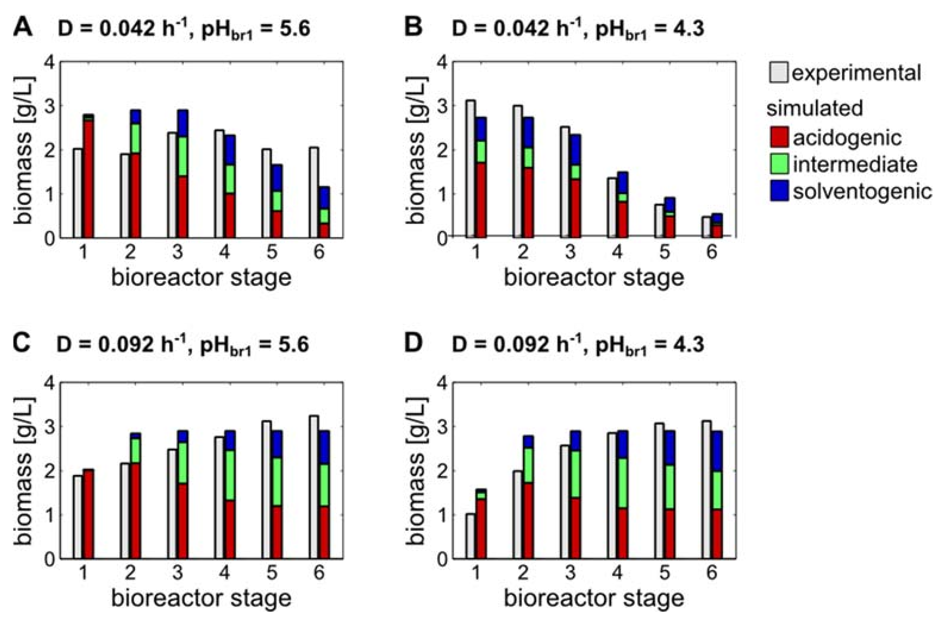
The simulations of the solvent concentrations are in very good agreement with the experimental data for all operating conditions, including those reserved for validation (Figure 4A,D,G,J). Moreover, the moderate variations of the organic acids concentrations, observed in the cascade at D = 0.092 h−1, are reproduced by the simulations (Figure 4H,K). However, the important changes in the acids concentrations along the cascade at D = 0.042 h−1 are not covered by the simulations (Figure 4B,E). Furthermore, the glucose concentrations are not simulated accurately with respect to the experimental variance in glucose measurements (Figure 4C,F,I,L). Still, the overall tendencies of the glucose concentrations along the cascade are qualitatively represented in the simulations. As shown in Figure 5, there is a high level of agreement between simulated and experimentally observed biomass concentrations for all operating conditions.
The discrepancies in the glucose concentrations are the main contributors to the weighted residual square sums, depicted in Table 3. Globally seen, the simulations had an equal quality for all bioreactor stages and all operating conditions (Table 3). Particularly good results were retrieved for the simulation of the cascade at D = 0.092 h−1 and pHbr1 = 4.3. It should be mentioned that also the experimental data set for D = 0.092 h−1/pHbr1 = 5.6), which has not been used in a parameter estimation, was simulated with comparable quality, validating the model with its parameter values.

3.3. Model-Based Predictions of Biomass Subpopulations Regarding Acidogenic, Intermediate and Solventogenic States

During the experiments, the total biomass concentration in each bioreactor stage was monitored. However, contrary to the long spread hypothesis that metabolically distinct states strictly correlate with different morphologies of Clostridium cells, more recent studies have clarified that solvent-forming cells can also appear with rod-shaped morphologies [16,22]. Thus, a straightforward microscopical characterization of the metabolic states of cells along the bioreactor cascade is not possible. Therefore, our model, postulating biomass subpopulations of acidogenic, intermediate and solventogenic states in each bioreactor (Figure 5), may provide insights into what are so far experimentally inaccessible process characteristics.
For fermentations with a pHbr1 of 5.6, the model predicts almost exclusively acidogenic cells in the first bioreactor of the cascade (Figure 5A,C). While at a dilution rate of 0.042 h−1, the proportion of solventogenic cells rises to 42% in bioreactor 6, the maximal proportion of solventogenic cells at a dilution rate of 0.092 h−1 (after a total mean residence time of 10.9 h) is only 26%. However, this exceeds the ratio of 21% solventogenic cells after 12 h mean residence time, predicted for the 3rd bioreactor of the cascade at 0.042 h−1 (Figure 5A,C, Table S2b).
In fermentations with a pHbr1 of 4.3, the model predicts significant cellular differentiation occurring already in the 1st bioreactor of the cascade (Figure 5B,D). At a dilution rate of 0.042 h−1 the predicted proportion of solventogenic cells is 19% in bioreactor 1 and increases to 36% along the cascade (Figure 5B, Table S2b). It is striking that under the respective operating conditions, the part of the intermediate cells is very low in all bioreactor stages. Its maximum of 18% is predicted for bioreactor 1 (Figure 5B, Table S2b). At the higher dilution rate, the proportion of solventogenic cells is significantly lower, with 4% and 31% in the 1st and 6th bioreactor, respectively (Figure 5D, Table S2b). The ratio of 31% solventogenic cells in the 6th bioreactor (after a total mean residence time of 10.9 h) corresponds roughly to the 29% of solventogenic cells, calculated for the 3rd bioreactor of the cascade at the low dilution rate. However, under this condition (mean residence time of 12 h at D = 0.042 h−1), the ratio of acidogenic (57%) to intermediate (14%) cells was still higher than in the last bioreactor stage at D = 0.092 h−1. For the latter, ratios of 39% acidogenic and 30% intermediate cells were predicted (Figure 5B,D, Table S2b).
It should be noticed that under all conditions the fraction of acidogenic cells was predicted as equal or larger than the fraction of solventogenic cells (Figure 5B, Table S2b).

3.4. Introducing a Feedback Loop for Recirculation of Fermentation Broth from Bioreactor 4 to Bioreactor 2

Our experimental investigations have shown that there is a high solvent productivity for the cascade at D = 0.092 h−1 and pHbr1 = 4.3. However, complete substrate conversion and maximal solvent concentrations were not reached within the 10.9 h of total mean residence time under these operating conditions. Thus, we introduced a feedback loop from bioreactor 4 to bioreactor 2 into the cascade (Figure 1B), aiming at an increase of the butanol productivity within the cascade. Butanol pulse experiments of Junne had raised the hypothesis that butanol can induce the solventogenic state of the cells [14], thus by recirculation of butanol-enriched fermentation broth, the differentiation process should be triggered according to this hypothesis. On the other hand, our here established model proposes that fermentation broth from bioreactor 4 is enriched with solventogenic cells, which can directly increase the butanol productivity in bioreactor 2.
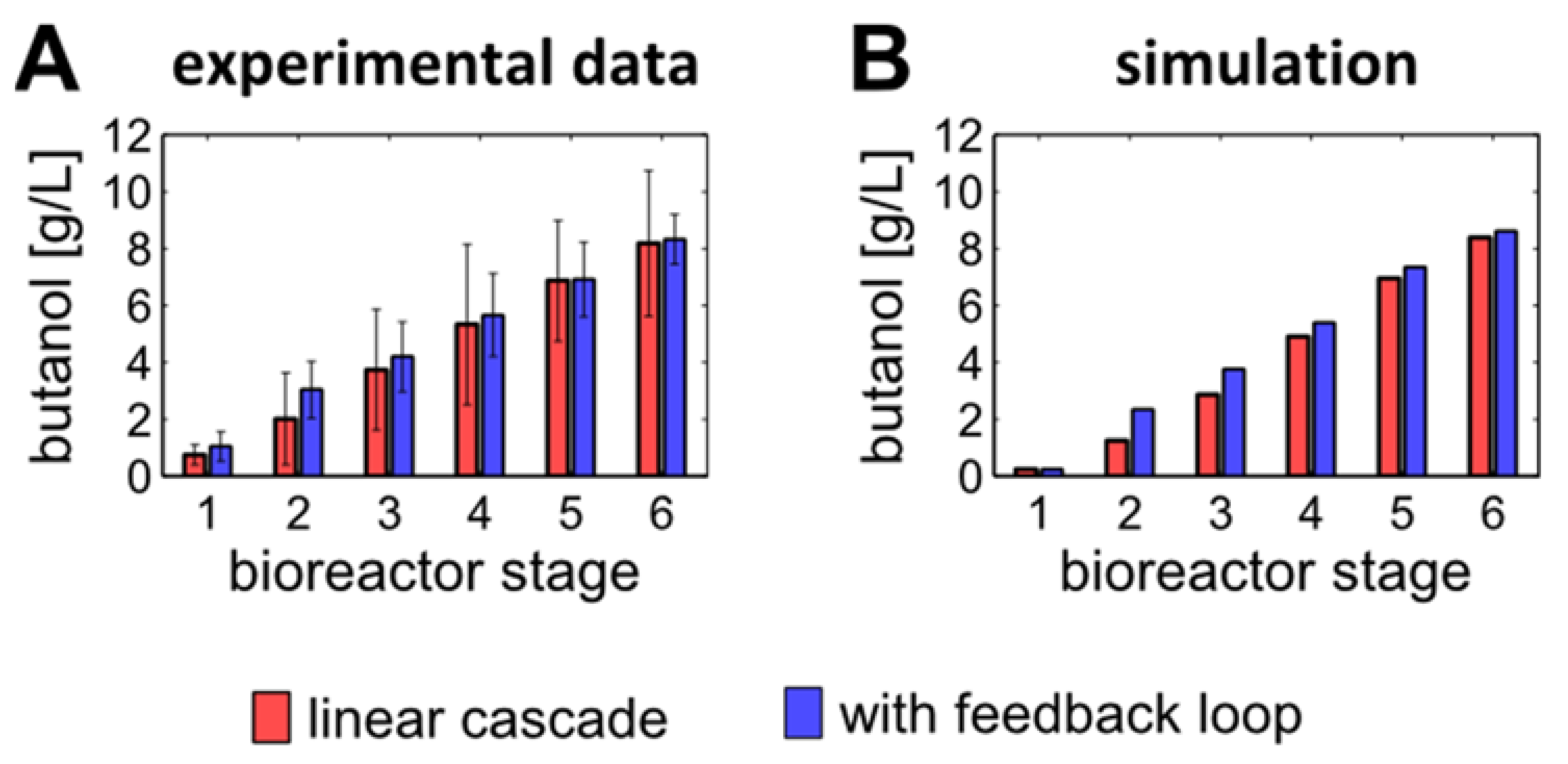
The recirculation flow Fback from bioreactor 4 to 2 was set to 0.055 L h−1, corresponding to a quarter of the feeding flow Fin. The outflow from the modified cascade, being equal to Fin, remained unchanged in comparison to the linear cascade (Figure 1B). The steady states observed in the cascade with feedback loop showed a 50% increase of butanol concentration in bioreactor 2 compared to the linear cascade (Figure 6A, Table S2a). Even though 94% of this increase in the butanol concentration has to be attributed to transport of butanol from stage 4 to 2, 6% of the increase resulted from an augmented metabolic activity in bioreactor 2. However, the beneficial effect of the feedback decreases in the following bioreactor stages. In bioreactor 4, the earliest termination point of the modified cascade, the butanol concentration was only 6% higher than in the linear cascade. In bioreactor 6 there were no more than 1.6% of butanol increase in the feedback loop system. Further, there was an important experimental variance, questioning the significance of the butanol increase (Figure 6A, Table S2a). However, simulations with the model, adapted to the feedback loop cascade also showed an increase in butanol concentration for bioreactor 2, 4 and 6 of 87.8%, 10.1% and 2.9%, respectively (Figure 6B, Table S2b). Thus, model simulation and experimental investigation indicates that a small increase of the butanol concentration can be achieved by introducing a recirculation into the cascade.
Results from computer simulations quantifying the influence of a recirculation flow show that if Fback is raised to 0.5 or 1 times Fin, the butanol concentration in the 6th bioreactor increases by 3.9% or 4.8% (in comparison to the linear cascade), respectively (Figure 7A). At the same time the model predicts a reduction of the organic acid uptake. As shown in Figure 7B, the acetic acid concentrations in bioreactor 2 and 3 decrease at higher recirculation rates. However, as a result of reduced organic acid uptake in bioreactor 5 and 6, the acetic acid concentrations at the outflow of cascades run at recirculation ratios of 0.25, 0.5 and 1, increase by 0.7%, 2.7% and 5.6% in comparison to the linear cascade, respectively (Figure 7B, Table S2b). Similar increases were modeled for the butyric acid concentrations (Table S2b). The proportion of solventogenic cells on the total biomass is predicted to notably increase in bioreactor 2, when the fermentation broth is recirculated (Figure 7C). However, up to bioreactor 4 of the feedback-loop cascade, the subpopulation proportions adapted to the levels of the linear cascade. At bioreactor 6 the part of solventogenic cells is predicted to be even slightly lower in the cascade with a recirculation ratio above a factor of 0.25 compared to the linear cascade (Figure 7C, data in Table S2b).
The experimentally observed butanol concentrations are in good agreement with the predictions of our model, based on a recirculation of already differentiated cells. However, the declining beneficial effect of the feedback loop along the cascade does not substantiate a significant effect of a possible butanol-triggered differentiation of cells to the solventogenic state proposed by Junne [14].

3.5. Product Concentrations, Productivities and Yields of ABE Processes Run in the Continuously Operated, Multi-Stage Bioreactor Cascades

High solvent concentrations as discussed above are essential for an efficient downstream process. However, productivity and yield, i.e., the time needed to produce the solvents and the efficiency in using the carbon and the energy stored in the substrate, are equally important criteria for an economic process. Looking at the productivities and yields at the outflow of the cascade (Table 4), one can note that although butanol and total solvent concentrations are lower at high dilution rates (D = 0.092 h−1), the productivities for butanol and solvents as well as the substrate yields are higher compared to D = 0.042 h−1 (Table 4). However, maximal product concentrations at D = 0.042 h−1/pHbr1 of 4.3 and 5.6 were already reached in bioreactor 3 and 5, respectively (Table 4, Figure 3, Table S2a). Thus, the cascade should be truncated to operate efficiently at this dilution rate. Regarding the maximal productivities instead of the maximal product concentrations, the optima are already reached in bioreactor 2 and 3 at D = 0.042 h−1/pHbr1 of 4.3 and 5.6, respectively (Table 4). Moreover, the yields were maximal in this range of the cascade with D = 0.042 h−1, i.e., at bioreactor 2 for pHbr1 of 4.3 and at bioreactor 4 for pHbr1 of 5.6 (Table 4). The maximal butanol and solvent productivities observed under the operating conditions applied in this study were 0.93 ± 0.14 g butanol L−1 h−1 and 1.29 ± 0.21 g total solvents L−1 h−1 at the outflow of bioreactor 2 in the cascade run at D = 0.042 h−1 and pHbr1 of 4.3 (Table 4). Yet the butanol and solvent concentrations at this state (7.4 ± 1.1 g butanol L−1 and 10.3 ± 1.7 g total solvents L−1) were rather low (Figure 3, Table S2a).
At a dilution rate of 0.092 h−1 and a pHbr1 of 4.3, the productivity was also found to be maximal in a cascade shortened to 5 stages. However, at these operating conditions, the productivities at the outflow of bioreactor 6 (0.75 ± 0.23 g butanol L−1 h−1 and 1.08 ± 0.36 g total solvents L−1 h−1) were only slightly lower than the maximal values at the outflow of bioreactor 5 (0.76 ± 0.23 g butanol L−1 h−1 and 1.08 ± 0.36 g total solvents L−1 h−1) (Table 4).
It is interesting to see that the maximum for the solvent production rate could be shifted to bioreactor 4 by introducing a feedback loop into the cascade (Table 4). However, the product concentrations in bioreactor 4 of the feedback loop cascade (5.7 ± 1.7 g butanol L−1 and 8.0 ± 2.0 g total solvents L−1) were significantly lower than those in bioreactor 6 of the same cascade (8.3 ± 0.9 g butanol L−1 and 11.9 ± 1.5 g total solvents L−1; Figure 3, Table S2a). Furthermore, the productivities in bioreactor 6 of the feedback loop cascade (0.76 ± 0.08 g butanol L−1 h−1 and 1.09 ± 0.14 g total solvents L−1 h−1) were slightly above those observed in the linear cascade (Table 4). The conversion yields of 0.18 g butanol g−1 glucose and 0.26 g total solvents g−1 glucose did not change between the feedback loop and the linear cascade operated at D = 0.092 h−1, pHbr1 of 4.3 (Table 4).
When operating the linear cascade at D = 0.092 h−1 and pHbr1 of 5.6, product concentrations, productivities and yields increased until the outflow of the cascade (Table 4). The low butanol and solvent concentrations of 4.8 ± 1.9 g butanol L−1 and 6.7 ± 2.7 g total solvents L−1 together with the comparatively low productivities and yields indicated that for this combination of dilution rate and pHbr1 the number of bioreactors in the cascade was not sufficient for effective conversion.

4. Discussion

Here we analyzed continuous ABE fermentations with suspended cells in a six-stage bioreactor cascade. Under the investigated operating conditions, a good compromise of high product concentrations and high volumetric productivity was found for the 3-stage (truncated) cascade, operated at pHbr1 of 4.3 and Fin of 0.1 L h−1 as well as for the 6-staged cascade, operated at pHbr1 of 4.3 and Fin of 0.22 L h−1, i.e., for total mean residence times in the cascade of 12 h and 10.9 h, respectively. Under these conditions, volumetric productivities and final butanol concentrations of 0.81 ± 0.04 g butanol L−1 h−1/9.7 ± 0.5 g butanol L−1 and 0.75 ± 0.23 g butanol L−1 h−1/8.2 ± 2.6 g butanol L−1 were reached, respectively.
These productivities are more than twice times higher than those observed in a two-stage ABE process [23], being the prototype of a multi-stage, continuous ABE fermentation. In that former work, residence times of 8 h in the first bioreactor (pH 4.3) and 33–42 h in the second bioreactor (pH 4.3) yielded final butanol concentrations of 10.5–12.6 g butanol L−1, but productivities of only 0.30–0.32 g butanol L−1 h−1 [23]. Since then a high number of continuous ABE fermentation strategies has been explored and published, being summarized in a matrix of final butanol concentrations and volumetric butanol productivities by Setlhaku et al. [24,25] This matrix shows that product concentrations above 13 g L−1 can only be reached in systems with integrated downstream processing, i.e., with multiple stages separating biological solvent production and technical product concentration (e.g., by gas stripping or pervaporation) [25,26,27,28,29]. Furthermore, this matrix illustrates that butanol productivities of 1 g L−1 h−1 and above are exclusively reached in systems with immobilized cells or cell retention [30,31,32,33]. A four-stage bioreactor cascade with Clostridium cells immobilized in a biofilm has been reported to yield up to 10.8 g butanol L−1 with a productivity of 9.2 g butanol L−1 h−1 [24].
However, the focus of our work was the establishment of a system that captures the temporal development of a batch process in a spatial dimension. Such an approximation of a plug flow bioreactor has been realized in the here-presented six-stage CCSTR. In contrast to biofilm or other fixed-bed bioreactors, cells from a certain metabolic phase can be retrieved from the CCSTR for further characterization or for a transfer into another environment. The characterization of metabolic phases in the ABE fermentation based on batch processes is linked to sophisticated prearrangements and poor reproducibility [16]. In the future, experimental characterization of individual cell populations in the different metabolic phases using flow cytometry [34,35,36,37], electrooptical measurements [38] or single cell RNA sequencing [39,40] can be applied to steady state samples of the CCSTR. Already, the here-presented model, showing good agreement with the experimental data, delivers prospects of the composition and the characteristics of the individual cell populations.
For instance, it is worth mentioning that the option for growth of intermediate and solventogenic cells, which had been newly introduced as an extension to an earlier model [20], resulted in maximal growth rate parameters of 0.46 h−1 and 0.41 h−1 for intermediate and solventogenic cells, respectively, after parameter estimation. These are lower than the maximal growth rate parameters of acidogenic cells, being 0.73 h−1. This result is in good agreement with the experimental analyses from other groups [22,41], showing that also under solventogenic conditions a stable steady state can be reached in single-stage continuous fermentation. However, this is characterized by a lower optical density than under acidogenic conditions [9,15,41], which might result from a lower maximal specific growth rate of the solventogenic cells.
In the model of Millat [9], simulating the pH-induced metabolic shift in a one-stage chemostat, two subpopulations—acidogenic and solventogenic cells—had been considered. However, in that model the dimensions of the subpopulations develop independently from each other, i.e., the model functions of two subpopulations are not linked to each other. In the here-presented model the development of the subpopulations is a differentiation process from acidogenic to intermediate and further to solventogenic cells, which depends on the concentration of undissociated acids. Implementing the mechanism of cell differentiation in the model, we followed an example of modeling the segregation of dihydroxyacetone-producing Gluconobacter axydans subpopulations [42]. One result of our simulation was that only a comparatively small proportion of cells, i.e., 26–40%, differentiated to solventogenic cells in the last bioreactor stage, while 29–54% remained in the acidogenic state. This contrasts with the model of Millat [9] where 100% of the acidogenic cells were transformed to 100% of solventogenic cells during the metabolic switch. However, shifting of subpopulation proportions rather than homogeneous differentiation agrees well with the recent insights into metabolic heterogeneity of bacterial communities, gained by now available single-cell analysis methods, e.g., single-cell RNA sequencing [40,43,44]. For instance, in antibiotic stress situations many bacterial populations tend to segregate into subpopulations of metabolic-active, antibiotic-sensitive cells and of persistent, metabolic-inactive, but antibiotic-resident cells. The latter group ensures the survival of the species and may profit from nutrients released by cell lysis of the first group once the antibiotic pressure is withdrawn [45]. Heterocyst formation of Nostoc punctiforme is another example for beneficial differentiation processes in bacterial populations [46].
Our model does not consider back differentiation from solventogenic cells to acidogenic cells, though shifting experiments in the single-stage continuous ABE fermentation propose that those are possible [47]. However, under the experimental conditions applied here we did not expect a back differentiation to occur. Furthermore, the remaining part of acidogenic cells even under externally solventogenic conditions, proposed by our model, offers the perspective that not a back differentiation, but rather overgrowing of the solventogenic by the acidogenic subpopulation leads to a backward shift from overall solventogenic to overall acidogenic conditions.
Validation and improvement of the here presented model predictions of the subpopulation composition will be enabled by future experimental investigations, e.g., by flow cytometry. So far, the model kept its predictive capacity even when switching operating conditions from the linear cascade to a cascade with feedback loop, which is another validation of the presented model.
The hypothesis from pulse experiments by Junne [14] proposes that butanol has an auto-inducing effect on the solvent production by promoting the differentiation process. Using the potential of our model, we simulated a feedback loop introducing solventogenic fermentation broth from bioreactor 4 (including ~21% of solventogenic cells and 5.3 g of butanol) into an earlier phase of the process in bioreactor 2. On one hand, one would expect a beneficial effect of the recirculated butanol on differentiation to solventogenic cells, which should even amplify itself after bioreactor 2. On the other hand there should be a beneficial effect, resulting from the recirculation of already differentiated solventogenic cells, which is expected to be rather constant in all bioreactors after entry from the feedback loop. However, here we observed significant higher solvent production in bioreactors 2 and 3 in the feedback loop cascade, but the beneficial effect declined in the later bioreactors, resulting in final butanol concentrations only 0.2 g L−1 higher than in the linear cascade. So there is no evidence for an amplification of solventogenesis triggered by butanol. However, the model prediction for the feedback loop cascade, matching the experimental results, indicates that a positive effect of a higher percentage of solventogenic cells in bioreactors 2 and 3 is compensated mainly due to reduced differentiation of new solventogenic cells caused by a decrease in the acetic and butyric acid concentrations.
As a new hypothesis, adding a feed of acetic and/or butyric acid to bioreactor 2 or 3 of the feedback loop cascade is one promising configuration that will be tested in the future with the here-introduced modeling tool and experimental setup for studies of the ABE fermentation.
Using the mathematical model not only cascade set-ups with additional feeding points, but also variations of the cascade with variable number of bioreactor stages, differently sized stages or cell recycling loops, can be evaluated and selected for experimental investigations. Thus, this work opens the door to a model-supported optimization of a continuous, multi-stage ABE process.

5. Conclusions

During the ABE process Clostridia go through different metabolic phases. With the here-presented cascade of continuous stirred tank reactors (CCSTR), it is possible to separate these phases in a spatial manner. Investigation and application of this reactor system is supported by a mathematical model, which combines two interacting levels of the process:
  • Reactor system model, depending on the configuration of the reactors, describing residence time distributions and their influence on microbial population fractions and metabolite concentrations;
  • kinetic model for microbial metabolism, allowing for populations with different metabolic activities, depending on the bioreactor environment.
The mathematical model, which fits the experimental steady state data of all operating conditions under investigation, indicates that even in the later bioreactor tanks of the cascade only a relatively small portion of the cells (about one third) is in the economically interesting solvent-forming state. Our attempt to increase the proportion of the solventogenic cells by introducing a feedback loop into the cascade from bioreactor 4 to bioreactor 2 resulted in a final butanol concentration of 8.3 g L−1 and a productivity of 0.76 g butanol L−1 h−1, which were only slightly higher than in the corresponding linear cascade. Achieving only this small improvement may be caused by the limited availability of substrate for conversion to solvents. The proposed addition of acetic and/or butyric acid to bioreactor 2 could overcome this limitation.
In the future the here-established multi-stage, ABE laboratory process with its corresponding mathematical description will serve as a tool for predicting and testing further fermentation strategies such as co-feeding of organic acids to different phases of the process. A collection of possible configuration modifications is shown in Figure 8.
The modifications in Figure 8 serve different purposes:
  • Adapting individual mean residence time in bioreactors by using different working volumes.
  • Moving cells and metabolites between bioreactor environments by feed-back and feed-forward loops.
  • Feeding additional substrates along the cascade, e.g., organic acids.
  • Biomass retention by separation and recycle.
Modeling metabolism in the cascade led to a more profound understanding of the shift from acidogenic to solventogenic state of the cells and the metabolic activity of physiologically different subpopulations. Together with the reactor model, allowing for simulation of any combination of configuration modifications, the performance of a cascade set-up with its operating conditions can be predicted.

Supplementary Materials

The following are available online at https://www.mdpi.com/article/10.3390/fuels2020007/s1, Figure S1a: Concentration and pH profiles during an exemplary fermentation, Table S1a: Variables used in the mathematical model, Table S1b: Variable kinetic model parameters optimized on the basis of the experimental data, Table S1c: Fixed kinetic model parameters derived from literature, experimental studies or estimations, Table S2a: experimental data, Table S2b: simulation results data.

Author Contributions

Conceptualization, P.G.; methodology, P.G., K.K. and S.T.; software, K.K.; validation S.T. and K.K.; experimental investigation, S.T.; resources, P.G.; data curation, K.K.; writing—original draft preparation, K.K. and S.T.; writing—review and editing, P.G.; supervision, P.G.; project administration, K.K., S.T. and P.G.; funding acquisition, P.G. All authors have read and agreed to the published version of the manuscript.

Funding

This research was funded by the German ministry “Bundesministerium für Bildung und Forschung” under the ERA-Net EuroTransBio-7 initiative, reference number 031A231C.

Institutional Review Board Statement

Not applicable.

Informed Consent Statement

Not applicable.

Data Availability Statement

Data is contained within the article and supplementary material.

Conflicts of Interest

The authors declare no conflict of interest. The funders had no role in the design of the study; in the collection, analyses, or interpretation of data; in the writing of the manuscript, or in the decision to publish the results.

References

  1. Pasteur, L. Quelques résultats nouveaux relatifs aux fermentations acétique et butyrique. Bull Soc. Chim. Paris 1862, 1862, 52–53. [Google Scholar]
  2. Poehlein, A.; Solano, J.D.M.; Flitsch, S.K.; Krabben, P.; Winzer, K.; Reid, S.J.; Jones, D.T.; Green, E.; Minton, N.P.; Daniel, R.; et al. Microbial solvent formation revisited by comparative genome analysis. Biotechnol. Biofuels 2017, 10, 1–15. [Google Scholar] [CrossRef] [PubMed]
  3. Dürre, P. Fermentative Butanol Production. Ann. N. Y. Acad. Sci. 2008, 1125, 353–362. [Google Scholar] [CrossRef] [PubMed]
  4. Weizmann, C. Improvement in the Bacterial Fermentation of Carbohydrates and in Bacterial Cultures for the Same. UK Patent 4845, 6 March 1915. [Google Scholar]
  5. Hijosa-Valsero, M.; Paniagua-García, A.I.; Díez-Antolínez, R. Biobutanol production from apple pomace: The importance of pretreatment methods on the fermentability of lignocellulosic agro-food wastes. Appl. Microbiol. Biotechnol. 2017, 101, 8041–8052. [Google Scholar] [CrossRef]
  6. Napoli, F.; Olivieri, G.; Russo, M.E.; Marzocchella, A.; Salatino, P. Continuous lactose fermentation by Clostridium acetobutylicum—Assessment of energetics and product yields of the acidogenesis. Enzym. Microb. Technol. 2012, 50, 165–172. [Google Scholar] [CrossRef]
  7. Sarchami, T.; Munch, G.; Johnson, E.; Kießlich, S.; Rehmann, L. A Review of Process-Design Challenges for Industrial Fermentation of Butanol from Crude Glycerol by Non-Biphasic Clostridium pasteurianum. Fermentation 2016, 2, 13. [Google Scholar] [CrossRef]
  8. Du, Y.; Zou, W.; Zhang, K.; Ye, G.; Yang, J. Advances and Applications of Clostridium Co-culture Systems in Biotechnology. Front. Microbiol. 2020, 11. [Google Scholar] [CrossRef]
  9. Millat, T.; Janssen, H.; Thorn, G.J.; King, J.R.; Bahl, H.; Fischer, R.-J.; Wolkenhauer, O. A shift in the dominant phenotype governs the pH-induced metabolic switch of Clostridium acetobutylicum in phosphate-limited continuous cultures. Appl. Microbiol. Biotechnol. 2013, 97, 6451–6466. [Google Scholar] [CrossRef]
  10. Engasser, J.-M.; Petitdemange, H. Influence of pH and undissociated butyric acid on the production of acetone and butanol in batch cultures of Clostridium acetobutylicum. Appl. Microbiol. Biotechnol. 1984, 19, 422–426. [Google Scholar] [CrossRef]
  11. Girbal, L.; Vasconcelos, I.; Saint-amans, S.; Soucaille, P. How neutral red modified carbon and electron flow in Clostridium acetobutylicum grown in chemostat culture at neutral pH. FEMS Microbiol. Rev. 1995, 16, 151–162. [Google Scholar] [CrossRef]
  12. Peguin, S.; Goma, G.; Delorme, P.; Soucaille, P. Metabolic flexibility of Clostridium acetobutylicum in response to methyl viologen addition. Appl. Microbiol. Biotechnol. 1994, 42, 611–616. [Google Scholar] [CrossRef]
  13. Rao, G.; Mutharasan, R. Alcohol production by Clostridium acetobutylicum induced by methyl viologen. Biotechnol. Lett. 1986, 8, 893–896. [Google Scholar] [CrossRef]
  14. Junne, S. Stimulus Response Experiments for Modelling Product Formation in Clostridium acetobutylicum Fermentations. Ph.D. Thesis, Technische Universität, Berlin, Germany, 2010. [Google Scholar]
  15. Grupe, H.; Gottschalk, G. Physiological events in Clostridium acetobutylicum during the shift from acidogenesis to sol-ventogenesis in continuous culture and presentation of a model for shift induction. Appl. Environ. Microbiol. 1992, 58, 3896–3902. [Google Scholar] [CrossRef] [Green Version]
  16. Jones, S.W.; Paredes, C.J.; Tracy, B.; Cheng, N.; Sillers, R.; Senger, R.S.; Papoutsakis, E.T. The transcriptional program underlying the physiology of clostridial sporulation. Genome Biol. 2008, 9, R114. [Google Scholar] [CrossRef] [PubMed] [Green Version]
  17. Gao, M.; Tashiro, Y.; Wang, Q.; Sakai, K.; Sonomoto, K. High acetone–butanol–ethanol production in pH-stat co-feeding of acetate and glucose. J. Biosci. Bioeng. 2016, 122, 176–182. [Google Scholar] [CrossRef]
  18. Wiesenborn, D.P.; Rudolph, F.B.; Papoutsakis, E.T. Thiolase from Clostridium acetobutylicum ATCC 824 and Its Role in the Synthesis of Acids and Solvents. Appl. Environ. Microbiol. 1988, 54, 2717–2722. [Google Scholar] [CrossRef] [Green Version]
  19. Junne, S.; Götz, P. Mathematical models for clostridia: From cultivation description to systems biology. In Systems Biology of Clostridium; Dürre, P., Ed.; Imperial College Press: London, UK, 2014; pp. 131–172. [Google Scholar]
  20. Karstens, K.; Trippel, S.; Görlitz, R.; Niebelschütz, H.; Marzocchella, A.; Götz, P. Modeling Physiological Differences in Cell Populations: Acetone-Butanol-Ethanol (ABE)-Fermentation in a Cascade of Continuous Stirred Tank Reactors. Chem. Eng. Trans. 2016, 49, 271–276. [Google Scholar] [CrossRef]
  21. Srivastava, A.K.; Volesky, B. Updated model of the batch acetone-butanol fermentation. Biotechnol. Lett. 1990, 12, 693–698. [Google Scholar] [CrossRef]
  22. Grimmler, C.; Janssen, H.; Krauβe, D.; Fischer, R.-J.; Bahl, H.; Dürre, P.; Liebl, W.; Ehrenreich, A. Genome-Wide Gene Expression Analysis of the Switch between Acidogenesis and Solventogenesis in Continuous Cultures of Clostridium acetobutylicum. J. Mol. Microbiol. Biotechnol. 2011, 20, 1–15. [Google Scholar] [CrossRef]
  23. Bahl, H.; Andersch, W.; Gotschalk, G. Continuous production of acetone and butanol by Clostridium acetobutylicum in a two-stage phosphate limited chemostat. Appl. Microbiol. Biotechnol. 1983, 17, 73. [Google Scholar] [CrossRef] [Green Version]
  24. Raganati, F.; Procentese, A.; Olivieri, G.; Russo, M.; Gotz, P.; Salatino, P.; Marzocchella, A. Butanol production by Clostridium acetobutylicum in a series of packed bed biofilm reactors. Chem. Eng. Sci. 2016, 152, 678–688. [Google Scholar] [CrossRef]
  25. Setlhaku, M.; Heitmann, S.; Górak, A.; Wichmann, R.D. Investigation of gas stripping and pervaporation for improved feasibility of two-stage butanol production process. Bioresour. Technol. 2013, 136, 102–108. [Google Scholar] [CrossRef] [PubMed]
  26. Ezeji, T.; Qureshi, N.; Blaschek, H. Production of acetone, butanol and ethanol by Clostridium beijerinckii BA101 and in situ recovery by gas stripping. World J. Microbiol. Biotechnol. 2003, 19, 595–603. [Google Scholar] [CrossRef]
  27. Qureshi, N.; Maddox, I.S.; Friedl, A. Application of continuous substrate feeding to the ABE fermentation: Relief of product inhibition using extraction, perstraction, stripping, and pervaporation. Biotechnol. Prog. 1992, 8, 382–390. [Google Scholar] [CrossRef]
  28. Xue, C.; Yang, D.; Du, G.; Chen, L.; Ren, J.; Bai, F. Evaluation of hydrophobic micro-zeolite-mixed matrix membrane and integrated with acetone–butanol–ethanol fermentation for enhanced butanol production. Biotechnol. Biofuels 2015, 8, 1–9. [Google Scholar] [CrossRef] [Green Version]
  29. Xue, C.; Zhao, J.; Lu, C.; Yang, S.-T.; Bai, F.; Tang, I.-C. High-titern-butanol production by Clostridium acetobutylicum JB200 in fed-batch fermentation with intermittent gas stripping. Biotechnol. Bioeng. 2012, 109, 2746–2756. [Google Scholar] [CrossRef] [PubMed]
  30. Napoli, F.; Olivieri, G.; Russo, M.E.; Marzocchella, A.; Salatino, P. Butanol production by Clostridium acetobutylicum in a continuous packed bed reactor. J. Ind. Microbiol. Biotechnol. 2010, 37, 603–608. [Google Scholar] [CrossRef]
  31. Survase, S.A.; Van Heiningen, A.; Granström, T. Continuous bio-catalytic conversion of sugar mixture to acetone–butanol–ethanol by immobilized Clostridium acetobutylicum DSM 792. Appl. Microbiol. Biotechnol. 2011, 93, 2309–2316. [Google Scholar] [CrossRef]
  32. Tashiro, Y.; Takeda, K.; Kobayashi, G.; Sonomoto, K. High production of acetone–butanol–ethanol with high cell density culture by cell-recycling and bleeding. J. Biotechnol. 2005, 120, 197–206. [Google Scholar] [CrossRef] [PubMed]
  33. Zhang, Y.; Ma, Y.; Yang, F.; Zhang, C. Continuous acetone–butanol–ethanol production by corn stalk immobilized cells. J. Ind. Microbiol. Biotechnol. 2009, 36, 1117–1121. [Google Scholar] [CrossRef] [PubMed]
  34. González-Peñas, H.; Lu-Chau, T.A.; Moreira, M.T.; Lema, J.M. Assessment of morphological changes of Clostridium acetobutylicum by flow cytometry during acetone/butanol/ethanol extractive fermentation. Biotechnol. Lett. 2014, 37, 577–584. [Google Scholar] [CrossRef] [Green Version]
  35. Patakova, P.; Linhova, M.; Vykydalova, P.; Branská, B.; Rychtera, M.; Melzoch, K. Use of fluorescent staining and flow cytometry for monitoring physiological changes in solventogenic clostridia. Anaerobe 2014, 29, 113–117. [Google Scholar] [CrossRef] [PubMed]
  36. Branska, B.; Pechacova, Z.; Kolek, J.; Vasylkivska, M.; Patakova, P. Flow cytometry analysis of Clostridium beijerinckii NRRL B-598 populations exhibiting different phenotypes induced by changes in cultivation conditions. Biotechnol. Biofuels 2018, 11, 99. [Google Scholar] [CrossRef] [Green Version]
  37. Tracy, B.P.; Gaida, S.M.; Papoutsakis, E.T. Development and Application of Flow-Cytometric Techniques for Analyzing and Sorting Endospore-Forming Clostridia. Appl. Environ. Microbiol. 2008, 74, 7497–7506. [Google Scholar] [CrossRef] [PubMed] [Green Version]
  38. Junne, S.; Klein, E.; Angersbach, A.; Goetz, P. Electrooptical measurements for monitoring metabolite fluxes in acetone–butanol–ethanol fermentations. Biotechnol. Bioeng. 2008, 99, 862–869. [Google Scholar] [CrossRef] [PubMed]
  39. Kolodziejczyk, A.A.; Lönnberg, T. Global and targeted approaches to single-cell transcriptome characterization. Brief. Funct. Genom. 2018, 17, 209–219. [Google Scholar] [CrossRef] [Green Version]
  40. Wang, J.; Chen, L.; Chen, Z.; Zhang, W. RNA-seq based transcriptomic analysis of single bacterial cells. Integr. Biol. 2015, 7, 1466–1476. [Google Scholar] [CrossRef]
  41. Janssen, H.; Döring, C.; Ehrenreich, A.; Voigt, B.; Hecker, M.; Bahl, H.; Fischer, R.-J. A proteomic and transcriptional view of acidogenic and solventogenic steady-state cells of Clostridium acetobutylicum in a chemostat culture. Appl. Microbiol. Biotechnol. 2010, 87, 2209–2226. [Google Scholar] [CrossRef] [PubMed] [Green Version]
  42. Bauer, R.; Hekmat, D. Development of a Transient Segregated Mathematical Model of the Semicontinuous Microbial Production Process of Dihydroxyacetone. Biotechnol. Prog. 2006, 22, 278–284. [Google Scholar] [CrossRef] [PubMed]
  43. Casadesús, J.; Low, D.A. Programmed Heterogeneity: Epigenetic Mechanisms in Bacteria. J. Biol. Chem. 2013, 288, 13929–13935. [Google Scholar] [CrossRef] [PubMed] [Green Version]
  44. Lidstrom, M.E.; Meldrum, D.R. Life-on-a-chip. Nat. Rev. Genet. 2003, 1, 158–164. [Google Scholar] [CrossRef] [PubMed]
  45. Veening, J.-W.; Smits, W.K.; Kuipers, O.P. Bistability, Epigenetics, and Bet-Hedging in Bacteria. Annu. Rev. Microbiol. 2008, 62, 193–210. [Google Scholar] [CrossRef] [PubMed] [Green Version]
  46. Meeks, J.C.; Campbell, E.L.; Summers, M.L.; Wong, F.C. Cellular differentiation in the cyanobacterium Nostoc punctiforme. Arch. Microbiol. 2002, 178, 395–403. [Google Scholar] [CrossRef] [PubMed]
  47. Janssen, H.; Fischer, R.J.; Bahl, H.; (Universität Rostock, Rostock, Germany). Personal communication, 2010.
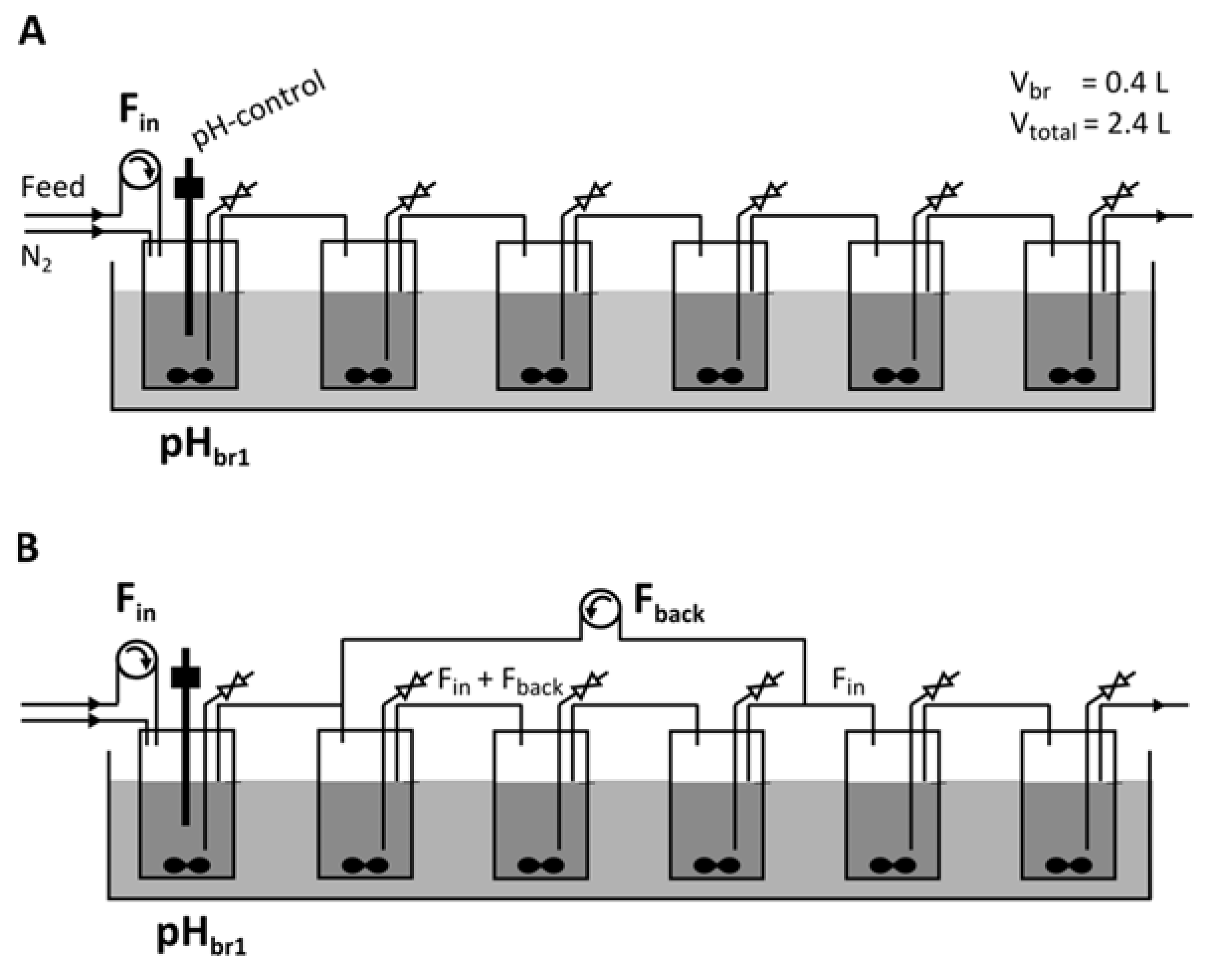
Figure 1. Set-up of the linear bioreactor cascade (A) and the cascade with feedback loop (B).
Fuels 02 00007 g001
Figure 2. Schematic representation of the mathematical modeling approach. Metabolites M = {x; glu; aa; ba; eth; act; but; PO4}; measured metabolites M’ = {x; glu; aa; ba; eth; act; but}; bioreactor stages k = {1; 2; 3; 4; 5; 6}; biomass subpopulations P = {A; I; S}.
Fuels 02 00007 g002
Figure 3. Steady states observed in the six-stage bioreactor cascade under 4 different operating conditions. Data represent means and experimental errors (maximum of standard deviations of individual or averaged data sets) of at least two independently observed steady states under the same operating conditions. For an overview of the individually observed steady states see Table S2a. Operating condition D = 0.042 h−1/ pHbr1 = 5.6; (A) Substrate and metabolites; (B) pH and biomass concentration. Operating condition D = 0.042 h−1/ pHbr1 = 4.3; (C) Substrate and metabolites; (D) pH and biomass concentration. Operating condition D = 0.092 h−1/ pHbr1 = 5.6; (E) Substrate and metabolites; (F) pH and biomass concentration. Operating condition D = 0.092 h−1/ pHbr1 = 4.3; (G) Substrate and metabolites; (H) pH and biomass concentration.
Fuels 02 00007 g003
Figure 4. Comparison of experimental and simulated data with respect to the experimental variations. Data sets D = 0.042 h−1/pHbr1 = 5.6 (AC), D = 0.042 h−1/pHbr1 = 4.3 (DF) and D = 0.092 h−1/pHbr1 = 4.3 (JL) were used for parameter optimization. Data set of D = 0.092 h−1/pHbr1 = 5.6 (GI) was used for validation of the optimized parameter set.
Fuels 02 00007 g004
Figure 5. Simulations of biomass concentration and subpopulation distribution. Experimentally observed biomass concentrations are compared to simulated biomass concentrations. The simulation additionally classifies biomass into acidogenic, intermediate and solventogenic subpopulations. Biomass data from D = 0.042 h−1/pHbr1 = 5.6 (A), D = 0.042 h−1/pHbr1 = 4.3 (B) and D = 0.092 h−1/pHbr1 = 4.3 (D) were used for parameter optimization. Data of D = 0.092 h−1/pHbr1 = 5.6 (C) serve as validation of the optimized parameter set.
Fuels 02 00007 g005
Figure 6. Butanol concentrations with and without feedback loop. Experiments and simulations were performed at Dbr1 = 0.55 h−1/pHbr1 = 4.3 and Fback = 0.055 L h−1 (corresponding to 0.25 Fin) (A) experimental data; (B) simulation.
Fuels 02 00007 g006
Figure 7. Simulation of butanol (A)/acetic acid (B) concentrations and proportions of solventogenic cells (C) along the cascade in dependency of the feedback flow Fback. Fin was kept constant at 0.22 L h−1.
Fuels 02 00007 g007
Figure 8. Possible modifications of the linear cascade of bioreactors to develop new fermentation strategies.
Fuels 02 00007 g008
Table 1. Feeding rate Fin, dilution rate Dbr1 for one bioreactor tank, dilution rate D for the cascade, residence time td in the reactor cascade.
Fin (L h−1)Dbr1 (h−1)D (h−1)td (h)
0.10.250.04224
0.220.550.09210.9
Table 2. Kinetic parameters of the mathematical model used for simulations.
Kinetic Model ParameterUnitAcidogenic CellsIntermediate CellsSolventogenic CellsAll
biomass evolution
mu_max_ (P)h−10.72730.46410.4204
KsPO4gKH2PO4 L−1 0.005
KsGLUgGLU L−1 6.5
KiBgBUT L−1 5
niB- 3
KdL gBUT−1 h−1 0.02
n_dGLU- 1.7332
KdGLUgGLU L−1 1.0353
acid production and uptake
r_aa_max_ (P)gAA gX−1 h−10.50970.02960
Y_aax_ (P)gAA gX−10.52240.50
k_AA_up_ (P)gAA gX−1 h−100.42240.9485
KsAAgAA L−1 0.6
r_ba_max_ (P)gBA gX−1 h−10.524800
Y_bax_ (P)gBA gX−10.500
k_BA_up_ (P)gBA gX−1 h−100.51.8594
KsBAgBA L−1 0.734
solvent production
r_eth_max_ (P)gETH gX−1 h−1000.2458
r_act_max_ (P)gACT gX−1 h−100.08660.6213
r_but_max_ (P)gBUT gX−1 h−100.02032.4485
phosphate and glucose uptake
Y_xpgX gKH2PO4−1 29
skmolC molGLU−1 1.1020
r_CO2_ (P)molC molGLU−10.001902.4904
n_C_GLUmolC molGLU−1 6
Y_xsgX gGLU−1 0.475
Y_aasgAA gGLU−1 0.9091
Y_basgBA gGLU−1 0.6667
Y_ethsgETH gGLU−1 0.6970
Y_actsgACT gGLU−1 0.5859
Y_butsgBUT gGLU−1 0.5606
differentiation
mu_d_ (P)h−10.16810.16810
K_UDA_ (P)g L−13.020300
n_iUDA_ (P)-4.317500
Table 3. Quality of simulation p for individual bioreactor stages and data sets given by the weighted residual square sum over all metabolites (see Figure 2). Data set of D = 0.092 h−1/pHbr1 = 5.6 was not used for parameter optimization and serves for validation of the estimated parameter set.
pBioreactor Stage
123456Σ
D = 0.042 h−1/ pHbr1= 5.64.1110.3611.898.0710.7012.3357.46
D = 0.042 h−1/ pHbr1= 4.315.079.801.8319.965.563.1955.40
D = 0.092 h−1/ pHbr1= 5.63.455.623.332.329.9715.9740.66
D = 0.092 h−1/ pHbr1= 4.35.602.362.332.211.881.8916.29
Σ28.2328.1419.3832.5628.1033.38169.80
Table 4. Overview of butanol and solvent productivities and yields under the investigated operating conditions.
Operating ConditionProduct ConcentrationVolumetric ProductivityYield
(g L−1)(g L−1 h−1)(g gGLU−1)
cbutanolcABErbutanolrABEYBUT/GLUYABE/GLU
D = 0.042 h−1/ pHbr1 5.6 f6.7 ± 3.38.9 ± 4.50.28 ± 0.140.37 ± 0.190.11 ± 0.060.15 ± 0.09
m7.2 ± 1.1 br59.7 ± 1.5 br50.42 ± 0.10 br30.56 ± 0.13 br30.13 ± 0.04 br40.17 ± 0.06 br4
D = 0.042 h−1/ pHbr1 4.3f9.6 ± 0.313.3 ± 0.70.40 ± 0.010.55 ± 0.030.16 ± 0.010.22 ± 0.01
m9.7 ± 0.5 br3 13.6 ± 1.1 br30.93 ± 0.14 br21.29 ± 0.21 br20.18 ± 0.05 br20.25 ± 0.07 br2
D = 0.092 h−1/ pHbr1 5.6 f4.8 ± 1.96.7 ± 2.70.44 ± 0.180.62 ± 0.250.14 ± 0.100.20 ± 0.14
m~~~~~~
D = 0.092 h−1/ pHbr1 4.3 f8.2 ± 2.611.8 ± 3.90.75 ± 0.231.08 ± 0.360.18 ± 0.090.26 ± 0.13
m~~0.76 ± 0.23 br51.08 ± 0.36 br5~~
D = 0.092 h−1/ pHbr1 4.3 f8.3 ± 0.911.9 ± 1.50.76 ± 0.081.09 ± 0.140.18 ± 0.060.26 ± 0.09
feedback loopm~~0.78 ± 0.20 br4*1.10 ± 0.28 br4*~*~*
f values based on final concentrations in br6 (outflow of the cascade); m maximal values for individual bioreactors (corresponding bioreactors are indicated as br2, br3, br4 and br5 respectively); * values from br2 and br3 were not considered as the feedback loop cascade cannot be truncated at these bioreactor stages; § irrationally high values from br1 with equally high standard deviations were not considered.
Publisher’s Note: MDPI stays neutral with regard to jurisdictional claims in published maps and institutional affiliations.