Article

Highly Flexible Polyaniline-Based Implantable Electrode Materials for Neural Sensing/Stimulation Applications

1
Biomedical Engineering Graduate Program, American University of Sharjah, Sharjah P.O. Box 26666, UAE
2
Department of Chemical Engineering, American University of Sharjah, Sharjah P.O. Box 26666, UAE
3
Department of Biology, Chemistry and Environmental Sciences, American University of Sharjah, Sharjah P.O. Box 26666, UAE
4
Department of Electrical Engineering, American University of Sharjah, Sharjah P.O. Box 26666, UAE
*
Author to whom correspondence should be addressed.
Electron. Mater. 2021, 2(3), 413-427; https://doi.org/10.3390/electronicmat2030028
Submission received: 27 June 2021 / Revised: 11 August 2021 / Accepted: 24 August 2021 / Published: 14 September 2021
(This article belongs to the Special Issue Feature Papers of Electronic Materials)

Abstract

:
Implantable bioelectrodes have the potential to advance neural sensing and muscle stimulation, mainly in patients with peripheral nerve injuries. They function as the transducer at the interface between the damaged nerve and the muscle which is controlled by that nerve. This work reports the fabrication and characterization of novel, low-cost, flexible bioelectrodes based on polyaniline (PANI) and supported with silicone polymer. The fabricated electrodes were evaluated for their electrical and mechanical characteristics. PANI was used as the main transducer component in this fabrication. The characterization methods included electrical conductivity, capacitive behavior, long-term electrical impedance, and mechanical evaluation. The results of the fabricated PANI-silicone-based samples displayed a bulk impedance of 0.6 kΩ with an impedance of 1.6 kΩ at the frequency of 1 kHz. Furthermore, the bioelectrodes showed a charge storage capacity range from 0.0730 to 4.3124 C/cm2. The samples were stable when subjected to cyclic voltammetry tests. The bioelectrodes revealed very flexible mechanical properties as observed from the value of Young’s modulus (in the order of MPa) which was less than that of skin. Hence, the PANI-based bioelectrodes reported herein showed promising electrochemical characteristics with high flexibility.

1. Introduction

Bioelectrodes act as transducers between the human body and the electronic instrumentation system, as they acquire the bioelectrical signals from the body or they can be used to stimulate the nerve/muscle. They function as an interface between the proximal end of the muscle and the injured nerve. In the last decade, neuroprosthetic applications have demonstrated promising results for traumatic neural injuries; hence, the demand for implantable electrodes has expanded [1,2]. There are various types of bioelectrodes, such as surface electrodes, muscle electrodes, and neural electrodes. However, implantable electrodes are a bit more complicated as they fall in direct contact with the intracellular body tissues. Therefore, materials used in implantable electrodes need to be extremely specific and well-studied to avoid any damage to the nerve tissues and mismatches which might induce immune body responses. Some of the most important factors which influence material selection are: (1) the electrode surface area, geometry, and surface condition required; (2) the electrical potential, current, and quantity of charge to be delivered or received; (3) the environmental requirements for which the electrode is going to be placed in which includes, but is not limited to, mass-transfer variables and solution variables; and (4) the engineering aspect of the bioelectrodes, which involves the cost of fabrication, availability of materials, strength, elasticity, and flexibility of the electrode to be fabricated.
Many of the stimulation methods have so far relied heavily on metals, such as gold and platinum [2]. These materials can cause mechanical damage to the soft nerve tissue. As a result, multiple attempts were conducted in the literature to develop new flexible electrode materials that could solve the previously mentioned challenge. The newly developed materials are based on conductive polymers [3,4] and precious metals [5,6,7,8,9]. Among the conductive polymers studied is polyaniline (PANI), which showed potential in sensor applications [3] and in tissue engineering [3,10]. However, one major drawback of using PANI is that it is a brittle material. Hence, in this paper, it is aimed at synthesizing flexible and potentially lower cost PANI-based bioelectrodes supported by the silicone matrix. Silicone polymer is flexible, stable, biocompatible, has a low cost, and thus a suitable supporting material. The fabricated electrodes will be evaluated for their electrochemical and mechanical properties to assess their potential as implantable electrode materials. To the best of the authors’ knowledge, such study has not been reported in the literature.

2. Materials and Methods

2.1. Sample Preparation

First, PANI was synthesized in our laboratories via the in situ polymerization reaction using aniline monomers (99.9% purity obtained from SIGMA, Taufkirchen, Germany). The procedure is well documented in the literature [10]. In brief, PANI was prepared by the oxidative polymerization of aniline using ammonium persulfate (APS) in a hydrochloric acid (HCl) solution in the presence of sodium dodecyl sulfate (SDS). After 24 h of reaction, the solid was collected by filtration, washed, and dried in an oven at 80 °C overnight. To prepare the bioelectrode samples, mixtures of different masses of polyaniline (PANI), silicone (the commercially available 100% silicone rubber clear (poly(dimethylsiloxane), hydroxy terminated, CAS Number 70131-67-8), and glycerol (certified ACS from Fisher, assay ≥ 99.5%, Saint Louis, MO, USA), shown in Table 1, were added. Glycerol is well known plasticizer [11]. The components were then mixed well (manually in a small plastic plate) for several minutes until they formed a paste. The paste mixture was then applied in a Teflon mold and allowed to dry for 24 h in the fume hood (at room temperature.

2.2. Sample Characterization

Electrochemical impedance spectroscopy (EIS) was used to determine the electrochemical properties (bulk impedance, impedance at 1 kHz, and electrical conductivity) of the dried electrode samples. To obtain the results in EIS, the four-probe method and a custom-made stainless steel cell were used. The results were displayed as a Nyquist plot.

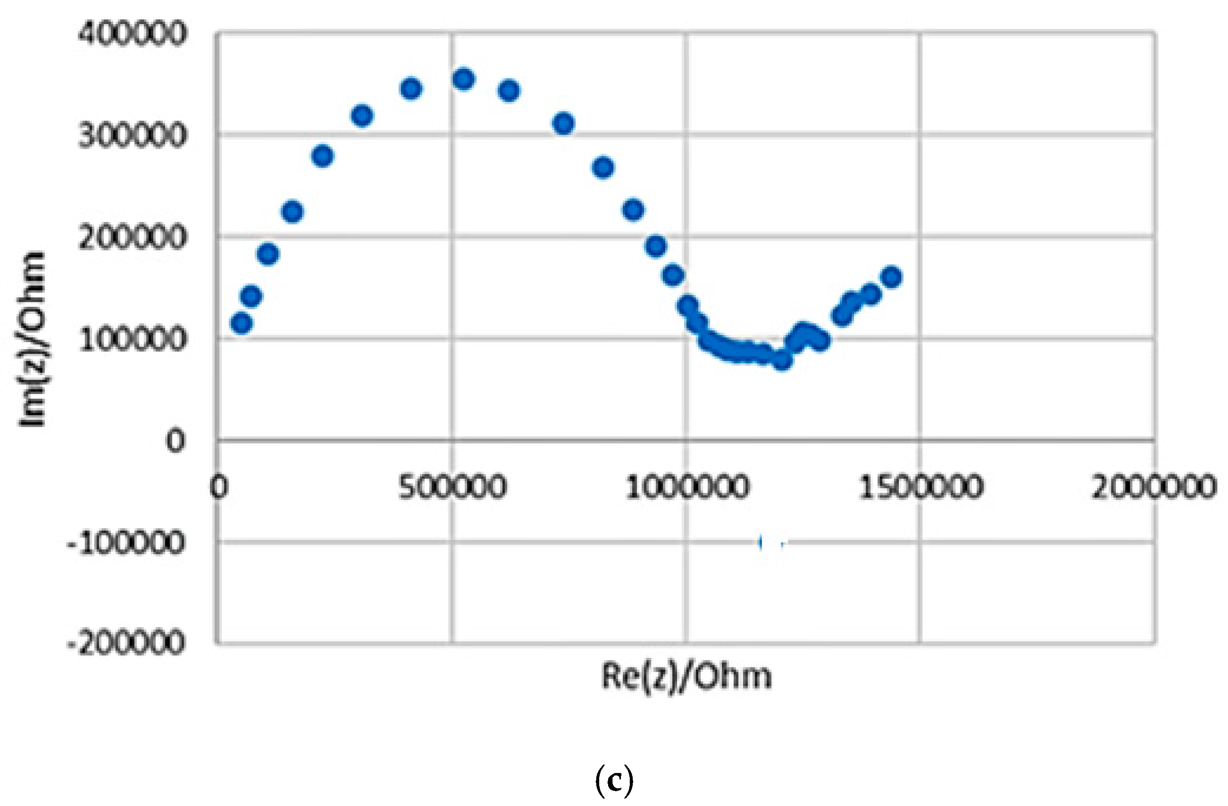
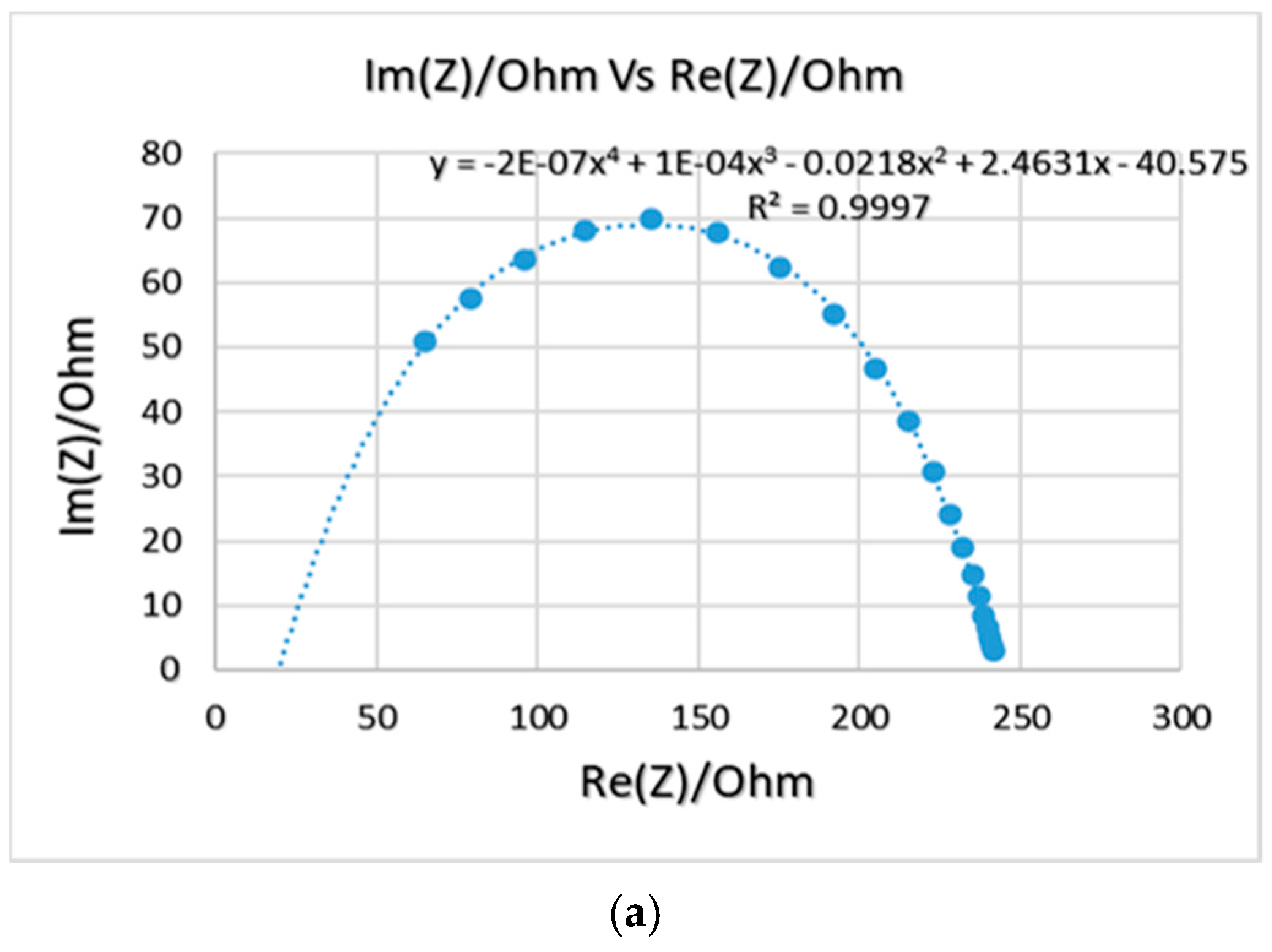
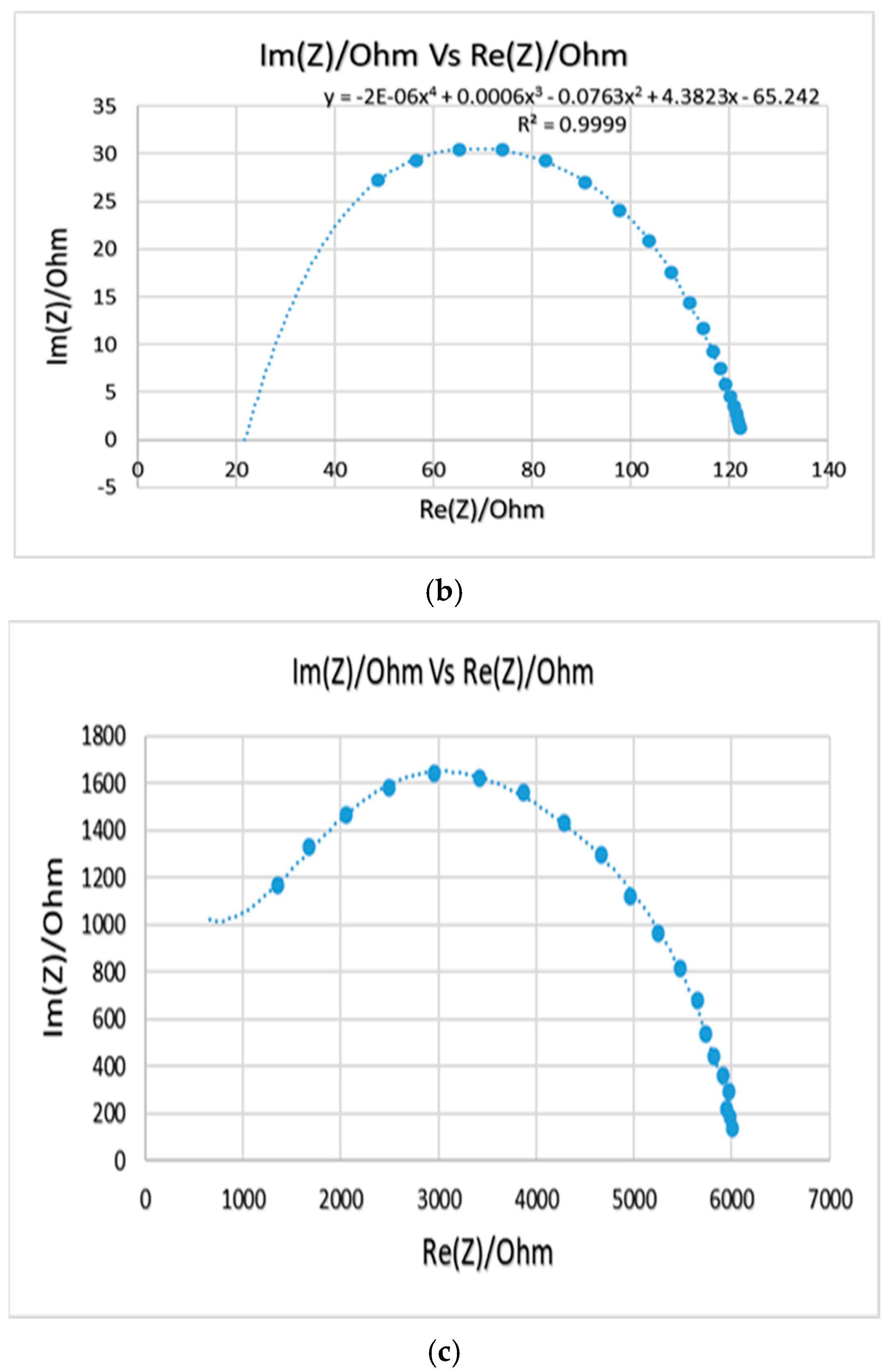
2.2.1. Electrochemical Impedance Spectroscopy (EIS)

EIS is a technique used to measure the electrical impedance of a device using a sinusoidal signal [12,13]. An impedance scale is observed by varying frequencies (100 Hz–7 MHz) over the desired range. An alternating current was applied, and the output was observed as a function of t frequency. The EIS calculations were carried out with the aid of a potentiostat (Biologic, model SP-200 with EC lab software v11.02), as shown in Figure 1a. The EIS data is provided as a Nyquist plot, which was analyzed to determine the sample’s bulk impedance. The sample impedance was also measured at a standard frequency of 1 kHz. The equation below was used to determine the conductivity of the fabricated samples (σ) [7]:
σ   = t R × A
where t, R, and A represent the thickness of the sample, electrical resistance, and cross-sectional area, respectively. The bulk impedance is the intercept of the curve with the x-axis, which can be determined by the Nyquist plot. One example of a Nyquist plot is shown in Figure 1b.

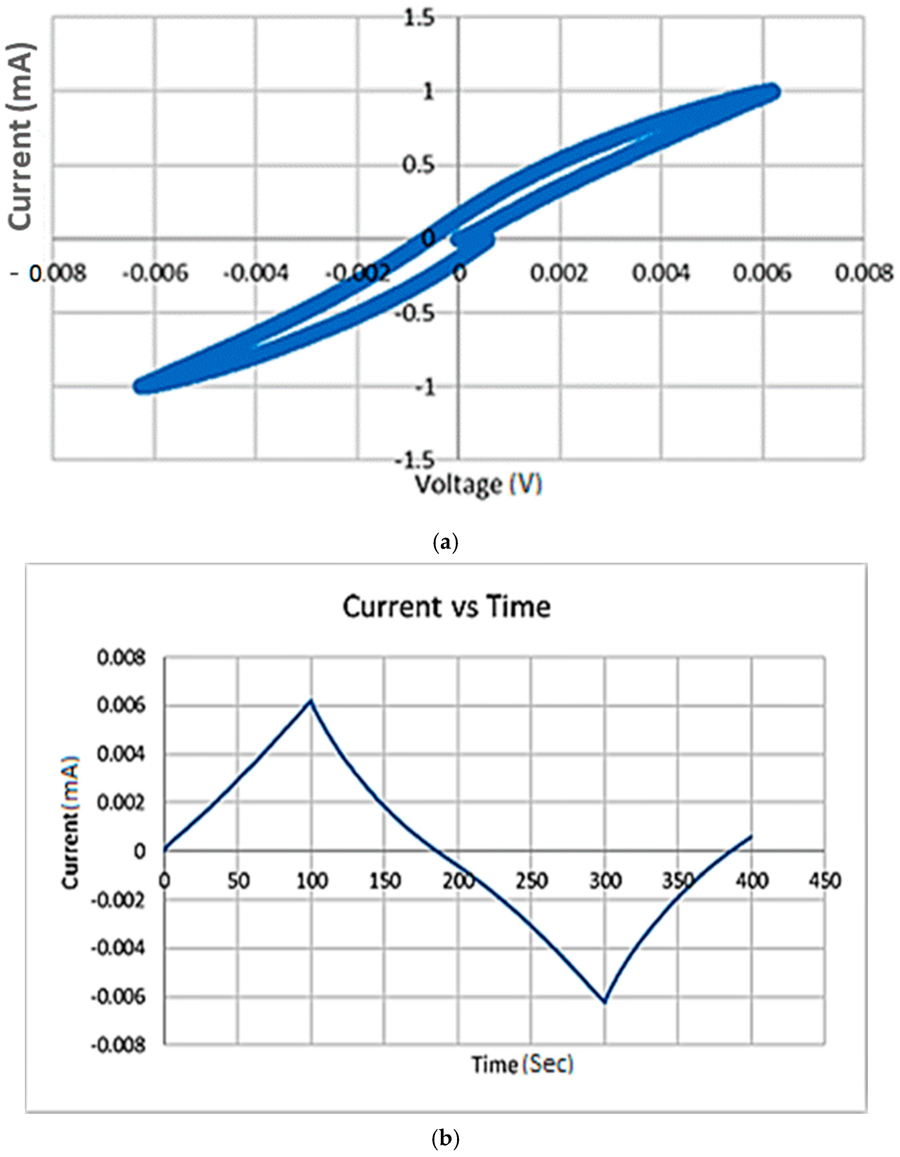
2.2.2. Cyclic Voltammetry (CV) Test

Cyclic voltammetry (CV) is an electrochemical test that enables the investigation of the sample’s stability (oxidation/reduction reactions) and the possible oxidation/reduction process. A potentiostat (SP-200, Biologic + cell with stainless steel electrodes) was used to perform the CV test, with a frequency range of 100 Hz–7 MHz and a voltage range of −2 V to 2 V. Moreover, the data was recorded and analyzed using EC lab software v11.02 (Biologic, Seyssinet-Pariset, France). The data was also used to calculate the charge capacity [14,15,16,17,18,19]. The charge capacity can be calculated by integrating the cathodal current area enclosed by CV and dividing it by the sweep rate of 10 mV/s.

2.2.3. Mechanical Testing (Young Modulus)

To calculate the Young Modulus of the sample, Instron 5582 Universal Testing Machine (using Instron Bluehill software) was used. This test is used to measure the relationship between the stress of the material and the strain of a bioelectrode sample. To find the Young Modulus, the slope of the straight line that appeared in the elastic deformation regime on the (stress/strain) graph was used to calculate the Young modulus using Equation (2) [11].
E   ( Young   modulus ) = Stress   ( б ) Strain   ( ε )

2.2.4. Long-Term Impedance Evaluation for the Bioelectrode Samples

This test was performed to investigate the effect of long-term implantation of the bioelectrode material properties. The samples were immersed in a phosphate-buffered saline (PBS) solution as the PBS pH is similar to that of the body (pH around 7.4). The samples stayed in the PBS solution for eight weeks with three–four days testing intervals (EIS and CV). The EIS and CV tests were performed to measure the change of the impedance with time. This test helped to understand how long the bioelectrode can stay within the body.

2.2.5. Electrocardiograph (ECG) Test

The purpose of this test was to conduct a simultaneous recording of the electrocardiograph (ECG) using standard Ag/AgCl electrodes and our fabricated electrodes. The ECG monitoring is a very important tool for medical diagnosis. The fabricated electrode materials in this work will be tested and compared to the commercially available Ag/AgCl electrodes in terms of the signal’s noise. For this purpose, several electrode samples were prepared in this work. The conductive side of the electrodes was placed on the participant’s limbs to record the ECG lead I. The electrodes were then connected to a differential amplifier. The output of the amplifier is then digitized and sampled using the PowerLab system and the “LabChart software” (LabChart, Colorado Springs, CO, USA). The recorded ECG signals are then stored for display or further processing.

3. Results

3.1. An Initial Evaluation of PANI-Silicone Electrodes Samples

In order to understand the effect of each component in the composite on the electrochemical and mechanical properties of the electrodes, a batch of three samples of varying ratios of PANI, silicone, and glycerol were prepared. In samples 1 and 2, the silicone composition was kept constant at 50% while the composition of PANI and glycerol was alternated between 20% and 30%. Sample 3 was then prepared with glycerol composition being similar to that of sample 2 while the ratios of PANI and silicone were modified. The results for the three composite PANI-silicone samples are shown in Figure 2 as Nyquist plots. The bulk impedance of the samples was determined from the Nyquist plot, as the intercept with the x-axis; the impedance at 1 kHz was determined, and the conductivity was calculated using Equation (1). By comparing the three prepared samples, in terms of impedance, sample 1 had bulk impedance and conductivity of 4 kΩ and 8.33 × 10⁻⁸ S/cm, respectively. At 1 kHz, sample 2 had the lowest impedance which is equal to 8.74 kΩ. In terms of composition, adding more PANI to the sample resulted in an increase in conductivity, an increase in the impedance at 1 kHz, and a decrease in the bulk impedance, but the samples appeared to be more brittle. Hence, this initial analysis showed that there is an optimum amount of PANI that can be used in the fabrication process and this amount can be further optimized. The results are summarized in Table 2. Compared to a PANI-coated foam electrode, the electrochemical results showed that the bulk impedance of sample 1 (4 kΩ) is lower than that of the PANI-coated foam electrode (7 kΩ) [3]. The impedance at 1 kHz of the prepared sample was equal to 28.4 kΩ which is much lower than that of the PANI-coated foam electrode (1.45 MΩ) [3]. Therefore, sample 1 was chosen for further characterization tests.
The CV test was then performed to enable the investigation of the samples’ stability (oxidation/reduction reactions) and the possible oxidation/reduction process. The results are shown in Figure 3 for sample 1, which is the best performing sample as observed in Table 2. The CV analysis for samples 2 and 3 (not shown here) revealed similar behavior and did not have any peaks in the plots as well. This means that there are no oxidation/reduction reactions taking place within all the samples while applying the alternative voltage, so the samples were all regarded as stable at these conditions. The charge storage capacity was then calculated by integrating the cathodal portion of the graph (which is the negative current capacity enclosed within the cyclic voltammetry), as shown in Figure 3, and then dividing it by the scanning rate (10 mV/s). Table 3 shows a comparison between this work and the literature values for some reported charge densities. The table shows that the charge capacity values obtained for the PANI-based samples prepared in this work were higher than those reported for PANI in the literature [20].
To assess the mechanical properties, the relationship between the stress and the strain was measured for the prepared bioelectrode sample (sample 1) and shown in Figure 4. The Young modulus was then calculated from the slope of the line that appeared in the elastic regime deformation as previously explained in Section 2.2.3 and was equal to 0.1468 MPa.
The comparison between the tested prepared sample of PANI-silicone-glycerol and the skin tissue showed that the Young modulus of this sample was equal to 0.1468 MPa compared to that of the skin tissue’s value of 83.33 ± 4.9 MPa [21,22]; which means that the fabricated electrode is very flexible with an elongation of approximately 307% as observed in the stress/strain graph (Figure 4). These findings show that the sample is less rigid than the skin, which means that the skin will deform the electrode but not the other way around. Thus, adding more comfort to the user in addition to being flexible as well.

3.2. Further Optimization for the PANI-Silicone Electrodes Samples

In order to improve the mechanical and the electrochemical properties of the fabricated electrodes, an additional batch of three samples with a varying ratio of PANI (by studying ratios less than 30%), silicone, and glycerol, was prepared. The mass percentage of PANI was varied between 6% and 20%. The objective was to optimize the bulk impedance and the impedance at 1 kHz, increase of the conductivity, increase the charge storage capacity, and increase the flexibility of the samples. The silicon percentage was varied between 50% and 72%, while the glycerol content was varied between 15% and 30%. This new batch of PANI-based samples was further subjected to electrochemical and mechanical characterization tests. The compositions are shown in Table 4.
The Nyquist plots for samples 4, 5, and 6 are shown in Figure 5. In terms of bulk impedance, sample 5 had the lowest value, and therefore the highest conductivity which are equal to 22 Ω and 1.51 × 10⁻⁵ S/cm, respectively. However, both samples 4 and 5 appeared to be very brittle compared to sample 6 (6% PANI, 72% silicone, and 22% Glycerol), which had a bit higher impedance and less conductivity (0.6 kΩ and 5.55 × 10⁻⁷ S/cm) but appeared more flexible. The EIS test showed that the electrochemical properties for sample 6 improved compared to the previously prepared samples. The bulk impedance reduced from 4 kΩ (sample 1) to 0.6 kΩ (sample 6), and the impedance at 1 kHz reduced from 28.4 kΩ (sample 1) to 1.6 kΩ (sample 6), which is much lower than that of the PANI-coated foam electrode reported in the literature (1.45 MΩ) [3].
The CV test was performed to enable the investigation of the new samples’ stability (oxidation/reduction reactions) and the possible oxidation/reduction process, as shown in Figure 6. The samples did not show any oxidation/reduction peaks, so the samples are considered as stable samples. The charge storage capacity was calculated as explained earlier. The average charge storage capacity was found to equal 0.0730 C/cm2.
By comparing the results of the prepared samples, sample 6 had the highest charge capacity compared to the other prepared samples. In order to assess the mechanical properties of sample 6, the Young modulus was estimated and found to be 75.312 MPa. The comparison of sample 6 with the previously prepared sample (sample 1) shows that the Young modulus for sample 6 (75.312 MPa) was higher than that of sample 1 (0.1468 MPa). A comparison between the prepared sample of PANI-silicone-glycerol and the skin tissue from the literature showed that the Young modulus of the prepared sample (sample 6) was equal to 75.312 MPa and it was lower than that of the skin tissue’s value of 83.33 ± 4.9 MPa [21].

3.3. A Study for Long-Term Stability in Phosphate-Buffered Saline (PBS) Solutions

This test was performed to investigate the effect of long-term stability of the bioelectrode material properties by the long-term immersion in phosphate-buffered saline (PBS) solution for 8 weeks. This test helped to understand how long the bioelectrode can stay within the body. To assess the values on impedance on the long-term immersion, a large sample of the following composition (similar to sample 6) was prepared (6% PANI, 72% silicone, and 22% glycerol). Then, it was cut into eight equal pieces. Their weights were recorded first. They were then immersed in eight different tubes; each tube consisted of 10.5 mL of 10% PBS solution. Every 3–4 days, the samples were removed and tested for their electrochemical properties. Before each test, the sample was separated from the tube and the weight of the sample was measured then left to dry for 15 min in the fume hood. The EIS-CV-EIS test was performed. The weight changes over the 8-week period are shown in Figure 7. It can be seen that the weight of the samples has increased after the immersion. This is probably due to the absorption of the PBS solution into the polymer matrix.
As previously discussed in this context, the readings from the CV are used to calculate the change of the charge storage capacity over the immersion period of 8 weeks, as shown in Table 5.
As for the long-term testing of sample 6, the shape of the samples did not change during the immersion phase. The weight of the samples before and after immersion was measured, and the weight after immersion increased in all the samples due to the soaking of the PBS solution. In terms of impedance, the bulk impedance had a variation of results over the immersion phase, which can be due to the soaking of the PBS solution, so the dimensions of the sample may change slightly (micro spaces); this change affected the electrochemical properties of the immersed sample (decreased the impedance). However, the impedance at 1 kHz and the charge storage capacity (CSC) varied slightly during the immersion phase, yet there was no behavior observed. This shows that the fabricated electrode sample can maintain resistant to the alteration of electrochemical properties when subjected to body fluids. In order to make sure that the given values of the fabricated electrodes were precise and accurate, a confidence interval test was performed with a composition similar to sample 6.

3.4. Evaluation of the Degree of Confidence

An evaluation for the degree of confidence was performed in this work for 20 prepared samples. The samples were prepared with a composition of (6% PANI, 22% Glycerol, and 72% Silicone) using a circular mold. The disk’s dimensions are radius = 9.415 mm and thickness = 2.87 mm. The variables considered were the impedance value at 1 kHz. The 95% confidence is the value that can be 95% true to the fabricated samples that were prepared in this paper. Before calculating the 95% confidence, the mean and the standard deviation should be found using Equations (3) and (4), respectively, and their values were used in Equation (5) to find the value of the 95% confidence. The EIS test was used to test and evaluate the electrochemical properties for all the samples to find the degree of confidence for the impedance values and frequency at 1 kHz.
x ¯   ( Mean )   = X i The   number   of   x   values   ( n )
S   ( Standard   Deviation ) = ( X i X ) 2 n 1
μ   ( 95 %   confidence ) = x ¯ 1.96 σ n     μ     x ¯ + 1.96 σ n
The results of the analysis showed a mean and a confidence interval of 4129.84 ± 2217.74 Ω.

3.5. ECG Test Results

The purpose of this test was to conduct a simultaneous recording of the electrocardiograph (ECG) using standard Ag/AgCl electrodes and the fabricated electrodes in this work. To perform this test, three samples were taken from the mold, having the same composition of sample 6 (6% PANI, 72% Silicone, and 22% Glycerol). A metal conductive tip was placed within the electrode samples and the tip was connected to the ECG probes. Those three electrodes were placed on the participants’ limbs (two hands, right leg) and the other end was connected to the “PowerLab 26T”. The results were compared to the standard Ag/AgCl electrodes, as shown in Figure 8.
An ECG comparison between the fabricated PANI electrodes and the standard Ag/AgCl electrodes was performed, as shown in Figure 8. The ECG result using the fabricated electrodes appeared to be promising, but the signal to noise ratio was a bit higher than that observed in the standard Ag/AgCl electrodes; the reason could be due to the motion artifact or the 50 Hz noise within the room. However, the flexibility of the current electrode material and the absence of other liquid electrolyte material promises for more levels of conformability [23].

4. Discussion

Overall, the electrochemical characterizations for the prepared samples in this work showed that the optimum PANI mass composition in the samples was 6%. The PANI-based prepared samples in this work showed a high flexibility as opposed to what have been previously reported in the literature with a Young modulus in the order of that similar to skin’s tissue. More specifically, the Young modulus has increased from 0.1468 MPa to 75.312 MPa, compared to the skin tissue’s Young modulus of 83.33 ± 4.9 MPa [21]. Thus, it can be clearly seen that the mechanical properties of the prepared PANI samples were very promising. During the stress–strain testing, the samples appeared to be noticeably elongated before breaking. The samples were mostly distinguished by their high elasticity and ductility in comparison with PANI, which is known to be a brittle material [24,25].
The PANI-based samples showed an impedance in the range of 0.6–4 kΩ with an impedance at 1 kHz in the range of 1.6–28 kΩ. The samples’ conductivities were in the order of 10−8 S/cm to 10−5 S/cm and this was achieved by optimizing the PANI content in the prepared samples. Another important aspect of the electrochemical characterization of the PANI-based samples in this work was the charge storage capacity, which represents the maximum amount of charge storage capacity (CSC) that can be allowed during one single pulse of the electrical stimulation process. The CSC reported in this work was from 0.0730 to 4.3124 C/cm2. The values reported here were very promising compared to the values reported in the literature for recently reported on sputtered iridium oxide film (SIROF) [26] and poly (3,4-ethylenedioxythiophene) (PEDOT):Nafion-based electrodes [27].
The long-term testing of PANI-based samples in this work showed no significant change on the samples’ shape/weight or electrochemical properties. Weekly observations reported that the samples did not significantly change in dimensions for 8 weeks. The weight of the PANI-based samples increased in the first few weeks of immersion probably due to the swallowing effect. However, in terms of the electrochemical properties, the bulk impedance as well as the impedance at 1 kHz appeared to be fluctuating during the immersion period but remained within the same order of magnitude. Similar fluctuations were observed in the CSC, but without a certain trend. Overall, the synthesized material showed that it can maintain stable electrochemical properties when exposed to body fluids and can do so for several weeks.
Given the small mass fraction of the PANI material used in the fabricated electrodes, they are characterized by being low-cost materials, especially when compared to poly (3,4-ethylenedioxythiophene):poly (styrene sulfonate) (PEDOT:PSS). Nonetheless, and to further characterize the electrode materials fabricated in this work, biocompatibility tests are still required.

5. Conclusions

This paper reported the fabrication of a highly flexible implantable electrode based on a conductive polymer (PANI) and silicone. PANI-based bioelectrodes were supported by the silicone matrix. Optimization experiments were conducted to find the best mass composition/combination of the materials. The best performing electrode sample has a PANI mass percentage of 6%. The EIS showed a bulk impedance of 0.6 kΩ. The cyclic voltammetry reported the stability of the prepared samples and was used to calculate the charge storage capacity. A charge storage capacity range from 0.0730 to 4.3124 C/cm2 was obtained for the sample that contained 6% PANI. Moreover, the mechanical testing was performed to calculate the Young modulus of the samples. The sample of 6% PANI showed high elasticity and ductility, with a Young modulus of 75 MPa. The fabricated electrodes were promising, especially when compared to the body’s skin tissue which is equal to 83.33 ± 4.9 MPa. The fact that the sample possessed a lower Young modulus than that of the skin makes the sample less rigid. This also means that the skin tissue is controlling the deformation process and will always deform the electrode but not the other way around. Thus, adding more comfort to the user. Future work will be directed towards evaluating the surface roughness of these electrodes using scanning electron microscopy (SEM), as well as evaluating their biocompatibility.
The long-term stability of the implantable electrodes was studied and evaluated. The results showed a promising electrochemical impedance. More work is recommended to improve the mechanical properties of the prepared samples as well as improving the ECG testing to minimize the signal to noise ratios of the current fabricated materials.

Author Contributions

Conceptualization, A.A.-O., H.A.-N., and M.H.A.-S.; methodology, N.A.; formal analysis, N.A., and Z.A.; investigation, N.A.; writing—original draft preparation, N.A.; writing—review and editing, N.A., Z.A., A.A.-O., H.A.-N., and M.H.A.-S.; visualization, A.A.-O., H.A.-N., and M.H.A.-S.; supervision, A.A.-O., H.A.-N., and M.H.A.-S.; project administration, A.A.-O., H.A.-N., and M.H.A.-S. All authors have read and agreed to the published version of the manuscript.

Funding

This research was funded by the graduate program of Biomedical Engineering MSBME at the American University of Sharjah.

Institutional Review Board Statement

The study was conducted according to the guidelines of the Declaration of Helsinki, and approved by the Institutional Review Board (or Ethics Committee) of the American University of Sharjah (protocol code 20-023/October 2020).

Informed Consent Statement

Not applicable.

Data Availability Statement

Not applicable.

Acknowledgments

The authors would like to acknowledge the support provided by the graduate program of Biomedical Engineering MSBME at the American University of Sharjah.

Conflicts of Interest

The authors declare no conflict of interest. The funders had no role in the design of the study; in the collection, analyses, or interpretation of data; in the writing of the manuscript, or in the decision to publish the results.

References

  1. Cogan, S.F. Neural stimulation and recording electrodes. Annu. Rev. Biomed. Eng. 2008, 10, 275–309. [Google Scholar] [CrossRef] [Green Version]
  2. Ratner, B.D.; Hoffman, A.S.; Schoen, F.J.; Lemons, J.E. Biomaterials Science: An Introduction to Materials in Medicine; Academic Press (Elsevier): Cambridge, MA, USA, 2004. [Google Scholar]
  3. Muthukumar, N.; Thilagavathi, G.; Kannaian, T. Polyaniline-coated foam electrodes for electroencephalography (EEG) measurement. J. Text. Instig. 2016, 107, 283–290. [Google Scholar] [CrossRef]
  4. Wang, Z.; Xu, J.; Yao, Y.; Zhang, L.; Wen, Y.; Song, H.; Zhu, D. Facile preparation of highly water-stable and flexible PEDOT:PSS organic/inorganic composite materials and their application in electrochemical sensors. Sens. Actuators B Chem. 2014, 196, 357–369. [Google Scholar] [CrossRef]
  5. Mohamed, O.; Al-Othman, A.; Al-Nashash, H.; Tawalbeh, M.; Almomani, F.; Rezakazemi, M. Fabrication of titanium dioxide nanomaterial for implantable highly flexible composite bioelectrode for biosensing applications. Chemosphere 2021, 273, 129680. [Google Scholar] [CrossRef] [PubMed]
  6. Cheung, K.C.; Renaud, P.; Tanila, H.; Djupsund, K. Flexible polyimide microelectrode array for in vivo recordings and current source density analysis. Biosens. Bioelectron. 2007, 22, 1783–1790. [Google Scholar] [CrossRef] [PubMed] [Green Version]
  7. Al-Othman, A.; Alatoom, A.; Farooq, A.; Al-Sayah, M.; Al-Nashash, H. Novel flexible implantable electrodes based on conductive polymers and Titanium dioxide. In Proceedings of the Middle East Conference on Biomedical Engineering, MECBME, Tunis, Tunisia, 28–30 March 2018. [Google Scholar] [CrossRef]
  8. Almufleh, N.L.; Al-Othman, A.; Al-Nashash, H.; Al-Sayah, M.H. Implantable Electrodes Based on Poly-aniline (PANI) and Silicone for Neural Sensing/Stimulations. In Proceedings of the Middle East Conference on Biomedical Engineering, MECBME, Amman, Jordan, 27–29 October 2020. [Google Scholar] [CrossRef]
  9. Alatoom, A.; Al-Othman, A.; Al-Nashash, H.; Al-Sayah, M. Development and Characterization of Novel Composite and Flexible Electrode Based on Titanium Dioxide. IEEE Trans. Components Packag. Manuf. Technol. 2020, 10, 1079–1087. [Google Scholar] [CrossRef]
  10. Shahadat, M.; Khan, M.Z.; Rupani, P.F.; Embrandiri, A.; Sultana, S.; Ahammad, S.Z.; Wazed Ali, S.; Sreekrishnan, T.R. A critical review on the prospect of polyaniline-grafted biodegradable nanocomposite. Adv. Colloid Interface Sci. 2017, 249, 2–16. [Google Scholar] [CrossRef]
  11. Lim, H.; Hoag, S.W. Plasticizer effects on physical-mechanical properties of solvent cast Soluplus® films. AAPS PharmSciTech 2013, 14, 903–910. [Google Scholar] [CrossRef] [PubMed] [Green Version]
  12. Yu, Z.; Xia, Y.; Du, D.; Ouyang, J. PEDOT:PSS Films with Metallic Conductivity through a Treatment with Common Organic Solutions of Organic Salts and Their Application as a Transparent Electrode of Polymer Solar Cells. ACS Appl. Mater. Interfaces 2016, 8, 11629–11638. [Google Scholar] [CrossRef]
  13. McAdams, E.T.; Jossinet, J.; Subramanian, R.; McCauley, R.G.E. Characterization of gold electrodes in phosphate buffered saline solution by impedance and noise measurements for biological applications. In Proceedings of the 2006 International Conference of the IEEE Engineering in Medicine and Biology Society, New York, NY, USA , 30 August–3 September 2006; pp. 4594–4597. [Google Scholar] [CrossRef]
  14. Bauerdick, S.; Burkhardt, C.; Kern, D.P.; Nisch, W. Substrate-integrated microelectrodes with improved charge transfer capacity by 30-dimensional micro-fabrication. Biomed. Microdevices 2003, 5, 93–99. [Google Scholar] [CrossRef]
  15. Etemadi, L.; Mohammed, M.; Thorbergsson, P.T.; Ekstrand, J.; Friberg, A.; Granmo, M.; Pettersson, L.M.E.; Schouenborg, J. Embedded ultrathin cluster electrodes for long-term recordings in deep brain centers. PLoS ONE 2016, 11, e0155109. [Google Scholar] [CrossRef] [PubMed]
  16. Lu, Y.; Li, Y.; Pan, J.; Wei, P.; Liu, N.; Wu, B.; Cheng, J.; Lu, C.; Wang, L. Poly(3,4-ethylenedioxythiophene)/poly(styrenesulfonate)-poly(vinyl alcohol)/poly(acrylic acid) interpenetrating polymer networks for improving optrode-neural tissue interface in optogenetics. Biomaterials 2012, 33, 378–394. [Google Scholar] [CrossRef]
  17. Cruz, A.M.; Casañ-Pastor, N. Graded conducting titanium-iridium oxide coatings for bioelectrodes in neural systems. Thin Solid Films 2013, 534, 316–324. [Google Scholar] [CrossRef]
  18. Harris, A.R.; Morgan, S.J.; Chen, J.; Kapsa, R.M.I.; Wallace, G.G.; Paolini, A.G. Conducting polymer coated neural recording electrodes. J. Neural Eng. 2013, 10, 016004. [Google Scholar] [CrossRef]
  19. Adpakpang, K.; Jin, X.; Lee, S.; Oh, S.M.; Lee, N.S.; Hwang, S.J. Unusually Huge Charge Storage Capacity of Mn3O4-Graphene Nanocomposite Achieved by Incorporation of Inorganic Nanosheets. ACS Appl. Mater. Interfaces 2016, 8, 13360–13372. [Google Scholar] [CrossRef]
  20. Jeon, J.W.; O’Neal, J.; Shao, L.; Lutkenhaus, J.L. Charge storage in polymer acid-doped polyaniline-based layer-by-layer electrodes. ACS Appl. Mater. Interfaces 2013, 5, 10127–10136. [Google Scholar] [CrossRef]
  21. Kalra, A.; Lowe, A.; Al-Jumaily, A.M. Mechanical Behaviour of Skin: A Review. J. Mater. Sci. Eng. 2016, 5, 4. [Google Scholar] [CrossRef] [Green Version]
  22. Hashim, A.; Abbas, B. Recent Review on Poly-methyl methacrylate (PMMA)-Polystyrene (PS) Blend Doped with Nanoparticles For Modern Applications. Res. J. Agric. Biol. Sci. 2019, 14, 6–12. [Google Scholar] [CrossRef]
  23. Pani, D.; Achilli, A.; Bonfiglio, A. Survey on Textile Electrode Technologies for Electrocardiographic (ECG) Monitoring, from Metal Wires to Polymers. Adv. Mater. Technol. 2018, 3, 10. [Google Scholar] [CrossRef]
  24. Yusoff, I.I.; Rohani, R.; Ng, L.Y.; Mohammad, A.W. Conductive polyelectrolyte multilayers PANI membranes synthesis for tunable filtration ranges. J. Mater. Sci. 2019, 54, 12988–13005. [Google Scholar] [CrossRef]
  25. Chen, P.-Y.; Hsu, C.; Venkatesan, M.; Tseng, Y.-L.; Cho, C.-J.; Han, S.-T.; Zhou, Y.; Chiang, W.-H.; Kuo, C.-C. Enhanced electrical and thermal properties of semi-conductive PANI-CNCs with surface modified CNCs. RSC Adv. 2021, 11, 11444–11456. [Google Scholar] [CrossRef]
  26. Ghazavi, A.; Maeng, J.; Black, M.; Salvi, S.; Cogan, S.F. Electrochemical characteristics of ultramicro-dimensioned SIROF electrodes for neural stimulation and recording. J. Neural Eng. 2020, 17, 016022. [Google Scholar] [CrossRef] [PubMed]
  27. Carli, S.; Bianchi, M.; Zucchini, E.; Di Lauro, M.; Prato, M.; Murgia, M.; Fadiga, L.; Biscarini, F. Electrodeposited PEDOT:Nafion Composite for Neural Recording and Stimulation. Adv. Healthc. Mater. 2019, 8, e1900765. [Google Scholar] [CrossRef] [PubMed]
Figure 1. (a) The experimental setup used to measure the characterization of the samples and the output as a Nyquist plot, and (b) is one example of the Nyquist plot.
Electronicmat 02 00028 g001
Figure 2. Nyquist plots for various samples: (ac) shown are for samples 1, 2, and 3, respectively. For compositions, refer to Table 1.
Electronicmat 02 00028 g002aElectronicmat 02 00028 g002b
Figure 3. Cyclic voltammetry (a) and the relationship between current and time (b) for sample 1 (the best performing sample) in Table 2. The scanning rate is 10 mV/s.
Electronicmat 02 00028 g003
Figure 4. Stress vs. strain of the material for the sample 1. (Stress in MPa, strain in mm/mm).
Electronicmat 02 00028 g004
Figure 5. Nyquist plots for samples 4 (a), 5 (b), and 6 (c). Compositions are shown in Table 4.
Electronicmat 02 00028 g005aElectronicmat 02 00028 g005b
Figure 6. Cyclic voltammetry for samples 4 (a), 5 (b), and 6 (c). Compositions are shown in Table 4.
Electronicmat 02 00028 g006
Figure 7. Change of the samples’ weight over the testing period.
Electronicmat 02 00028 g007
Figure 8. (a) ECG result using the standard Ag/AgCl Electrodes (the blue graph is without filtering and the orange line is after the filtering). (b) ECG result using the fabricated electrodes (the blue curve is without filtering and the orange curve is after the filtering).
Electronicmat 02 00028 g008
Table 1. Comparison between different prepared electrode mass compositions.
SamplePANI (%)Silicone (%)Glycerol (%)
Sample 10.9 g (30%)1.5 g (50%)0.6 g (20%)
Sample 20.6 g (20%)1.5 g (50%)0.9 g (30%)
Sample 30.3 g (10%)1.8 g (60%)0.9 g (30%)
Table 2. Comparison between different prepared electrode mass compositions.
SamplePANI (%)Silicone (%)Glycerol (%)Bulk Impedance (kΩ)Impedance at 1 kHz (kΩ)Conductivity
(S/cm)
Sample 1305020428.48.33 × 10−8
Sample 22050305.38.746.28 × 10−8
Sample 310603050.19716.65 × 10−9
PANI-Coated Foam Electrodes---71.45 × 10³ [3]-
PEDOT: PSS---2.232.54 [4]0.26 [4]
Table 3. A comparison table for charge capacity for the first batch of the prepared samples.
CompositePANI (%)Silicone (%)Glycerol (%)Charge Capacity (C/cm2)Reference
Sample 13050204.3124This work
Sample 220 5030 14.4945This work
Sample 310 60 30 0.2575This work
Graphene---1.42 × 10⁻⁹[19]
Polyaniline---0.02[20]
Table 4. Comparison between different prepared electrode samples.
SamplePANI (%)Silicone (%)Glycerol (%)Bulk Impedance (kΩ)Impedance at 1 kHz Conductivity (S/cm)
41570150.02579.1396 Ω1.33 × 10⁻⁵
52050300.02256.5978 Ω1.51 × 10⁻⁵
6672220.6001.6 kΩ5.55 × 10⁻⁷
PANI-coated foam electrode---7.001.45 MΩ [3]-
Table 5. Change of the charge storage capacity in the long-term PANI-based samples.
WeekCharge Storage Capacity (C/cm2)
10.67
22.92
30.097
49.13
50.997
62.25
70.923
82.55
Publisher’s Note: MDPI stays neutral with regard to jurisdictional claims in published maps and institutional affiliations.

