Abstract
Variable transmission applications for light control or energy saving based on electrochromic materials have been successfully applied in the past in the building, sports, or automotive fields, although lower costs and ease of fabrication, installation, and maintenance are still needed for deeper market integration. In this study, all-printed large area (900 cm2 active area) flexible electrochromic devices were fabricated, and an autoregulating self-power supply was implemented through the use of organic solar cells. A new perspective was applied for automotive light transmission function, where portability and mechanical flexibility added new features for successful market implementation. Special emphasis was placed in applying solution-based scalable deposition techniques and commercially available materials (PEDOT-PSS as an electrochromic material; vanadium oxide, V2O5, as a transparent ion-storage counter electrode; and organic solar modules as the power supply). A straightforward electronic control method was designed and successfully implemented allowing for easy user control. We describe a step-by-step route following the design, materials optimization, electronic control simulation, in-solution fabrication, and scaling-up of fully functional self-powered portable electrochromic devices.
1. Introduction
Electrochromic technology, which offers reversible and gradual light transmission modulation over visible or infrared wavelength range controlled by an applied electrical signal, has been developed during the last 50 years. From the beginning, special focus has been placed on the possibility of achieving energy-savings through variable transmission windows. It has been estimated that heating, ventilation, and air conditioning (HVAC) savings can reach up to 30% [1,2,3,4,5]. While being a highly ambitious and desirable objective in a context of mitigating climate change effects and a sustainable architecture, and despite a number of companies commercializing these kinds of technologies, massive implementation of these windows has been severely hindered. Some factors may be pointed out like fabrication and installation complexity, high cost, exigent stability standards to compete with conventional windows, exceeding 20 years, or big device surfaces required, among others. A more subjective reason could be that the final user does not immediately perceive the benefits (in terms of energy or electricity bill savings).
An opposite situation can be found for a similar device, attenuating rearview mirrors, probably the most successful application in the field of variable light transmission [6]. These devices can be presently found in millions of cars around the world. Success of this application probably lies in a comparatively lower cost, less exigent stability, and the real time perception of its functionality by the end user.
In this context, we believe that additional steps in electrochromic technology development, translated into easier scalable fabrication processes, lower final costs, and ease of installation may help in its further implementation. Niche applications, less exigent in terms of durability or optical requirements, could act as a testbed for faster technology development.
In this study, we propose a transmission modulating application for light comfort of passengers in vehicles. This application has recently been implemented in the aviation field [7] and is commercially offered, based on other variable transmission technologies like liquid crystal displays (LCDs) [8] for privacy purposes. Again, these devices suffer from high installation complexity or cost ($1400–2500 for the latter). To overcome some of these drawbacks and extend the device practical characteristics, we propose a portable, self-powered, mechanically flexible device. We put special emphasis on the use of in-solution scalable deposition and assembly processes, with the aim of showing the viability for future roll-to-roll (R2R) fabrication.
It is particularly interesting to note that due to the intended application, the device will be mainly used in the presence of solar irradiation. This makes it unnecessary to add charge storage components, therefore greatly simplifying the design complexity and fabrication, presumably lowering the final device cost.
Solar powered electrochromic devices have been successfully explored in the past [9], and the possibility of having autonomous devices is very attractive [10,11,12]. Significant efforts have been made in the development of all-in-one photoelectrochromic devices [13,14,15,16], mainly based on modified dye-sensitized solar cell architectures. However, obtaining bistability in both color states represents a challenge. Tandem monolithically deposited stacks have also been proposed using semi-transparent solar cells [17,18,19]. A side-by-side independent architecture, where proper functioning of the photovoltaic and the electrochromic components can be independently tuned and optimized, has appeared as an interesting approach [20,21,22]. The impressive development of printed solar cells [23,24] in the last two decades, whether polymer-based or perovskite-based, add exciting opportunities for the integration of both technologies. Reasonable expectations about having a fully-printed R2R massive production of these combined devices could be soon fulfilled and the first steps in this direction have been made [25,26].
This study aims to contribute to the scientific and engineering knowledge in this pursued objective by proposing and fabricating portable, mechanically flexible, fully-printed, self-powered variable transmission devices for light-comfort of passengers in vehicles. Real-scale fully functioning devices showing around 25% contrast at 650 nm (all layers included), and switching speeds lower than 30 s, for approximately 1200 cm2 total surface, were successfully fabricated and tested.
2. Materials and Methods
2.1. Materials
Lithium trifluoromethanesulfonate (LiCF3SO3) (96%, Aldrich, Saint Louis, MO, USA), propylene carbonate (PC) (99%, Aldrich), vanadium (V) triisopropoxide oxide (96%, Alfa-Aesar, Haverhill, MA, USA), 2-propanol (ACS, 99.5%, Alfa-Aesar), poly(ethylene glycol)diacrylate (Aldrich), 2,2-dimethoxy-2-phenylacetophenone (99%, Aldrich), glass beads (<106 μm, Aldrich), and Clevios PEDOT-PSS PH1000 (Heraeus, Hanau, Germany) were used as received. ITO-PET (60 Ohms/sq, Aldrich) was used as the substrate.
2.2. Deposition and Characterization
An airbrush spray gun (Iwata-Eclipse HP-BC, Anest Iwata-Medea, Inc., Portland, OR, USA) connected to a nitrogen line and mounted on a computer numerical control (CNC) station (HEIZ, CNC High-Z S-series, Heiz, Geldern, Germany) was used for the deposition of PEDOT-PSS and V2O5 films. A Cary 50 UV–Vis spectrophotometer (Agilent, Santa Clara, CA, USA) was used for the optical characterization of films and devices. A Biologic SP-50 potentiostat-galvanostat (Biologic-SAS, Seyssinet-Pariset, France) was used for the electrochemical measurements.
2.3. Device Fabrication
Devices were assembled using a previously reported photo-crosslinkable electrolyte gel [27], exposed to UV-light for 10 min. A UV-lamp (Vilber-Loumat VL-4-L, 365 nm, 4 W, Vilber, Collégien, France) was used to cure the electrolyte gel. Figure 1 shows the layer scheme of the devices and the coloration-bleaching mechanism.

Figure 1.
Scheme of the constituent layers of the constructed devices and the corresponding redox mechanism for coloration and bleaching.
Organic photovoltaic cells (Infinity PV-PV foil, infinityPV ApS, Jyllinge, Denmark) were used for powering the electrochromic devices. An ABET AM1.5 Class AAA solar simulator was used for characterization of the photovoltaic cells. J–V curve characterization was carried out by applying a sweeping voltage with a programmable voltage source (Keithley Mod. 230, Keithley Instruments, Cleveland, OH, USA) and measuring current with an electrometer (Keithley Mod. 6514, Keithley Instruments, Cleveland, OH, USA). Technique setup and data acquisition were controlled by a LabView-based software developed in our laboratory.
3. Results and Discussion
The following section describes the route followed for the fabrication of fully-functional large area devices. First, we carried out an optoelectrochemical characterization process of the individual constituent materials of the electrochromic devices to determine the optimum deposition conditions. Second, we characterized the electrical performance of the organic solar cells to be used and performed an initial scaling-up of the assembled devices. The data provided allowed us to simulate the electronic configuration of the integrated system, in order to properly dimension the photovoltaic components and switching control. Finally, functional prototypes were fabricated, integrated, and tested in outdoor operating conditions.
3.1. Optimization of Electrochromic Components
3.1.1. Working Electrode
Films of PEDOT-PSS (Clevios PH-1000, Heraeus, Hanau, Germany) were spray coated over small surface areas (approx. 2 cm2) to different thicknesses in order to optimize the expected electrochromic response. To allow a proper drying and homogeneous deposition, substrates were placed over a hot plate surface maintaining a constant temperature of 90 °C. Resulting films of variable thickness (Figure 2A) were optically and electrochemically characterized following the method previously proposed by our group [28,29], which briefly consists on the determination of absorbance (transmittance) at the two limiting color states and correlate those values with the redox capacity of the film, or another significant deposition or functional variable (i.e., thickness). Figure 2 shows the results obtained in this study when PEDOT-PSS films were cycled between −0.8 and 0.6 V vs. the Ag wire reference electrode (calibrated 0.1 V vs. NHE). Linear plots of absorbance vs. redox capacity (for clear and dark states) were obtained (Figure 2B) and translated into exponential decay relations of transmittance vs. redox capacity (due to the existing exponential relation between absorbance and transmittance) (Figure 2C). When subtracted to obtain the contrast value (contrast is defined as the difference between transmittance in two different color states), maximum of the function can be easily identified, therefore obtaining that contrast value and the corresponding optimized deposition conditions. This point is marked in Figure 2C for visual identification, although the exact values were obtained through derivative of the resulting contrast function. Further mathematical details can be found elsewhere [28,29]. Optimized contrast and corresponding redox capacity values for these experimental conditions were 35% at 650 nm and 1.6 mC/cm2, respectively (it is worth noting that this reported contrast value includes the contribution of the PET-ITO substrate, which considerably diminished the optical performance). When optical contribution of the PET-ITO substrate was eliminated (usual transmittance values for these substrates are 80% across the visible range), the obtained contrast was approx. 45%, in agreement with previously reported values for PEDOT-PSS [30]. Optimized deposition solution for spraying was 30 μL/cm2 of PH1000.
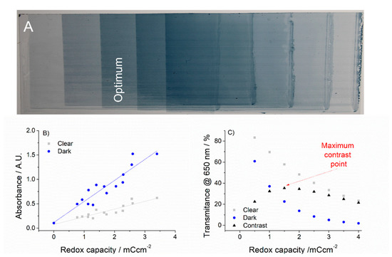
Figure 2.
(A) Variable thickness PEDOT-PSS films deposited over the PET substrate where the optimum film is highlighted. (B) Absorbance vs. redox capacity of the films in their oxidized (clear) and neutral (dark) states. (C) Transmittance vs. redox capacity in their oxidized (clear) and neutral (dark) states, together with the corresponding contrast, where the maximum contrast value is identified (red arrow).
3.1.2. Ion Storage Counter Electrode
Vanadium pentoxide (V2O5) was used as the charge balancing counter electrode due to its good transparency, adequate electrochemical activity, and the possibility of in-solution deposition by printing techniques. The use of transparent counter electrodes in order to maximize the optical contrast and the color purity in electrochromic devices has been remarked in numerous studies [31,32,33]. While in most cases transition metal oxides are deposited via vacuum related techniques, with an increase in energy requirements and constraints for scale-up massive production, different alternative routes for in-solution processing are presently available, mainly based on the use of soluble precursors and subsequent thermal conditioning [34,35]. In this study, we used a modified route to that proposed by M. Hajzeri et al. [36] (same conditions except the initial precursor solution concentration, which in this case was 0.025 M vanadium triisopropoxide in isopropanol). Briefly, the precursor solution is deposited over the substrate and subsequently submitted to an annealing process (150 °C for 20 min). This method was originally applied to ITO-glass substrates. However, direct application of such high temperatures to PET substrates for a long time results in partial melting and the loss of mechanical integrity. In order to adapt this high temperature process to our PET-ITO substrates, we performed a series of lower temperature annealing cycles. We found that good-quality electrochemically active films could be obtained without compromising the mechanical properties of the PET substrates, reducing the temperature to 120 °C and annealing time to just 10 minutes (Figure 3B,C), how the resulting redox capacities obtained for films annealed at different temperatures from 25 °C to 150 °C, and different annealing times from 1 to 20 min). Optimized resulting films were optically and electrochemically characterized (cycling between −0.5 and 1.5 V vs. Ag wire reference electrode (calibrated 0.1 V vs. NHE) and found to obtain enough redox capacities to compensate the optimized PEDOT-PSS previously calculated with negligible optical contribution (transparency in both states was around 80% including the ITO-PET substrate contribution) (Figure 3). Films with approx. 3 mC/cm2 redox capacity were obtained using 15 μL/cm2 spraying solutions, comfortably exceeding the required redox capacity to compensate for that of the corresponding working electrode.
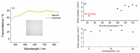
Figure 3.
(A) Visible transmittance spectra of the obtained V2O5 films in their neutral and oxidized states. Inset: a picture of one film as deposited. (B) Redox capacity of V2O5 films for different annealing temperatures (no annealing (25 °C) point is included). (C) Redox capacity of V2O5 films for different annealing times.
3.2. Devices Assembly and Electronic Control Design
3.2.1. Power Supply Characterization
Due to its mechanical characteristics, the versatility for dimensioning a range of different power requirements and the possibility of a complete printing processing fabrication, which correlate with the desired characteristics of the proposed devices, polymer-based organic solar panels in the form of cuttable foils (commercially available Infinity PV-PV foil), were used in this study. The foil was composed of a number of serially connected stripes that can be cut at certain lengths for the needed voltage output. In order to obtain the necessary information for a proper dimensioning of the final system, basic electrical parameters for one of the stripes (7.6 cm2) were obtained under standard AM1.5 illumination. Figure 4 shows a representative J–V curve obtained and the associated open circuit voltage (Voc), short-circuit current (Jsc), maximum power voltage (Vmp), maximum power current (Jmp), power conversion efficiency (PCE), and fill factor (FF).
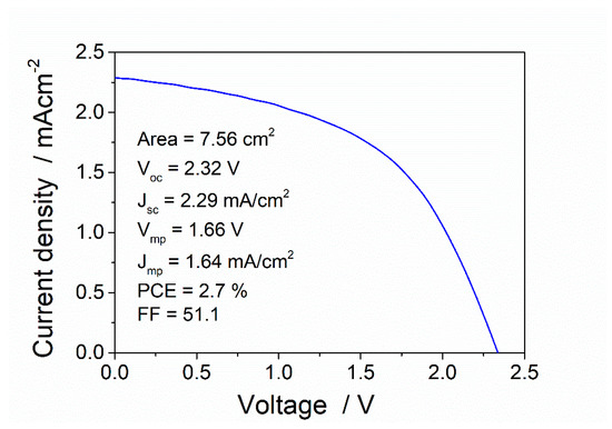
Figure 4.
Electrical characterization of a single stripe from an Infinity-PV foil organic solar panel under AM 1.5 solar irradiation.
3.2.2. Device Scale-Up and Operating Conditions
Functional devices were assembled by using a photo-crosslinkable UV-curable gel electrolyte. The gel electrolyte was poured over one of the substrates and the second substrate was directly placed face-to-face in order to assemble the device. Subsequent photocuring of the gel electrolyte allowed this component to act as a double-function layer, providing ionic contact for the device and adhesion between components. Increasing active area devices were constructed and tested, in order to establish the proper operating conditions while scaling-up, starting from small surface, 3 cm2 to 110 cm2 (10 × 11 cm2), and finally 360 cm2 (9.5 × 38 cm2). Optoelectrochemical characterizations were obtained in a two-electrode configuration, where PEDOT-PSS films acted as a working electrode and V2O5 as the counter/reference electrode. As described in Figure 1, coloration of the device was obtained through the reduction of PEDOT-PSS (usually accompanied by the insertion of cations, Li+ in this case) and the corresponding oxidative reaction at the counter electrode. Bleaching was achieved through the oxidation of PEDOT-PSS. Complementary redox reactions of V2O5 were achieved through the intercalation-deintercalation of lithium cations. As previously stated, optical contribution of V2O5 was negligible in both states. Operating potentials ranged from +0.5 V to −3 V for the smaller surfaces up to +0.5 V to −4 V for the bigger ones, mainly due to the higher electrical resistance offered by the ITO-PET substrate for increasing dimensions. Contrasts obtained for these devices ranged between 20–25%, showing that the PEDOT-PSS films were completely cycled and the optical contribution of the V2O5 was kept to the minimum. Figure 5 shows clear and dark states for a 360 cm2 assembled device under D65 standard illumination conditions (some inhomogeneities in the color transition can be observed, possibly due to variable gel thickness, as a consequence of manual assembly of the device for such big surfaces).

Figure 5.
Clear and dark states of a 360 cm2 active area PEDOT-PSS/V2O5 assembled device, under D65 standard illumination conditions, cycled between +0.5 V to −4 V.
When interpreting these results, it must be taken into account that again, these contrast values correspond to real values obtained with the contribution of all device layers. Considering that for a complete assembled device three more layers are required, namely the gel electrolyte, V2O5 film, and another ITO-PET substrate, once these contributions are eliminated (approx. transmittance 80%), the resulting contrast value was around 32%, very close to the optimized values obtained in previous sections for PEDOT-PSS plus one ITO-PET substrate.
3.2.3. Electronic Control Design
In order to assess the viability of the integration of photovoltaic cells as a power supply for the electrochromic devices, and to obtain an adequate dimensioning of the system, an electronic modeling through equivalent circuits was carried out. PSpice software (ORCAD-Cadence) was used to simulate the current–voltage response of the organic solar cells and their integration with the transient charge–discharge processes of the electrochromic window.
To simulate the photovoltaic cells, a single-diode model equivalent circuit was considered. Figure 6 shows the equivalent circuit and the representative parameters used to generate the I–V curves, according to the previous results obtained (Figure 4) for a single stripe.
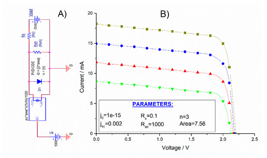
Figure 6.
(A) Equivalent circuit used for the modeling of organic solar cells. (B) Generated I–V curves for different irradiance values: Green line (600 Wm−2), red line (800 Wm−2), blue line (STC 1000 Wm−2), and yellow line (1200 Wm−2). Inset: Parameters used for generating the corresponding I–V curves.
According to the power requirements of the tested electrochromic devices, additional voltage would be needed for a proper function. Figure 7 shows the equivalent circuit for a proposed four cell-string (serially connected) module able to provide Vmp = 7.7 V, Imp = 12.73 mA with a power of Pmp = 98.021 mW. The system was slightly over-dimensioned (as the voltage requirements for the electrochromic devices was at least 4.5 V) to account for possible low irradiance conditions.
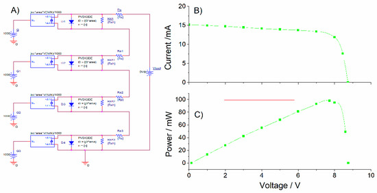
Figure 7.
(A) Equivalent circuit used for a 4-cell string (serially-connected) organic solar module. (B) Generated I–V curves for standard irradiance STC 1000 Wm−2. (C) Power–voltage curve identifying the maximum power point.
The electrical behavior of the electrochromic device was also simulated by a corresponding equivalent circuit. An electrochromic device is an electrochemical cell that undergoes charge and discharge processes. Components (electrodes, electrolyte, wire connections) can be modeled by resistive/capacitive RC nets [37]. We used a simplified model in which the electrochromic device is represented by a single RC tandem (R1 + C1 in the scheme shown in Figure 8) and the addition of parasitic resistances corresponding to wiring or ITO substrate resistance due to the big areas considered (R2–R4 in the scheme). Transient current-time responses were simulated for different C1 values (ranging from 0.001 to 0.1 F). Values of R1 = 400 ohm and C1 = 0.01 F (cyan line in Figure 8 graphs) showed the better agreement with the previously obtained current–time electrochromic device evolutions, with voltages between 0–5 V and charge–discharge times around 20 s.
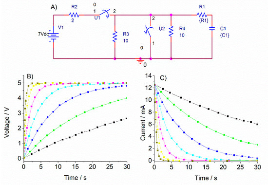
Figure 8.
(A) Equivalent circuit used for an electrochromic device. (B) Simulated voltage–time transients for different R and C values (C) Simulated current–time transients for different R and C values.
The integrated system with the previously proposed 4-cell string (serially connected) module and the RC fitted electrochromic device was designed and the voltage–time and current–time transients generated (Figure 9).
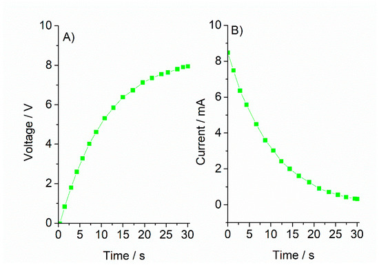
Figure 9.
(A) Voltage–time transient and (B) current–time transient for an integrated photovoltaic-electrochromic system, simulated under STC (1000 Wm−2, 25 °C).
Interestingly, the system showed a notable autoregulating capacity, where voltage and current supplied by the photovoltaic module is automatically adapted to the requirements of the electrochromic device in the pursued time scale (color changes in sub-minute range). This constitutes a relevant result from an electronic control design perspective, since it is a low-complexity control mechanism that simplifies the architecture and fabrication processes. A simple user-controlled ON–OFF switch mechanism was proposed and implemented (practical details will be described in the next section).
3.3. Functional Portable Self-Powered Devices
According to the previously described specifications, we fabricated fully functional large-scale devices. Electrochromic films were deposited according to the optimized obtained conditions and assembled manually with a final UV photocuring laminating step. Electrical adhesive aluminum tape was adhered along the perimeter of the ITO-PET substrates to improve electrical contact. Electrochromic devices fabricated this way were scaled up to a 900 cm2 active area.
Photovoltaic stripes (Infinity PV double foil) were connected to the devices, where the electronic control, as mentioned in the previous section, was achieved by a user-controlled ON–OFF system consisting of two push-buttons (white and black, respectively), indicating the corresponding coloring process (white for bleaching, black for darkening). Power is maintained as long as the buttons are pressed, therefore allowing intermediate transmissive states according to the user preferences. White flexible PVC frames were implemented, resulting in a final device surface with an integrated power supply and electronic control of 1200 cm2 (30 × 40 cm2) (Figure 10A). Removable suction pads were added to the device for adhesion to different surfaces, allowing multiple stick on–off cycles and full portability.
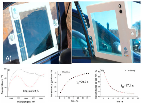
Figure 10.
(A) Final prototype of a portable, self-powered flexible electrochromic “curtain” for automotive use. Active coloring area of 900 cm2, full-device area 1200 cm2. (B) Transmittance spectra in the colored and bleached states (C,D) Kinetics for bleaching and coloring processes.
Optoelectrochemical characterization of the devices was carried out, resulting in a contrast of 23% at 650 nm (for 0 to 4.5 V applied potentials), in agreement with the previously obtained values for lower surface devices (Figure 10B).
In order to assess the adequate performance for the pursued application, kinetics of the color transitions were also monitored. Transmittance variation for the coloring and bleaching processes were fitted to exponential decays following the method proposed by Hassab et al. [38], identifying the time constants (time spent for 63 % of the stationary transmittance change) as τ(bleaching) = 9.72 s and τ(coloring) = 5.69 s. Therefore, t95 (time required for 95% of the complete transmittance change) were t95 (bleaching) = 29.2 s and t95 (coloring) = 17.1 s. Kinetics evolutions and the corresponding fittings are shown in Figure 10C.
4. Conclusions
We proposed and fabricated new portable, mechanically flexible, printed, self-powered variable transmission devices for the light-comfort of passengers in vehicles.
All device active components (PEDOT-PSS, V2O5) are commercially available and fully-printable. By optimizing the deposition conditions, designing and simulating an adequate electronic control, and a proper scaling-up process, real-scale fully functioning devices showing approx. 25% contrast at 650 nm, and switching speeds lower than 30 s for a 900 cm2 color active area (1200 cm2 total surface including power supply and switching control) were successfully constructed and tested.
The results of this study, which build upon a number of previous efforts in the scientific community toward easier and scalable fabrication routes of electrochromic and photovoltaic technologies, represent a further step to showing the commercial viability of this approach.
Author Contributions
Conceptualization, J.P. and R.R.; Methodology, J.A., J.P. and A.U.; Investigation, J.P., J.A., A.C.-S., R.L.-V. and R.R.; Data curation, J.P., J.A., A.U. and R.L.-V.; Writing—original draft preparation, J.P.; Writing—review and editing, A.C.-S., R.R., J.P., J.A., A.U. and R.L.-V.; Funding acquisition, J.P. and A.U. All authors have read and agreed to the published version of the manuscript.
Funding
This research was funded by the Ministerio de Ciencia e Innovación-Agencia Estatal de Investigación (AEI-MICINN, Spain) grant number PID2019-104272RB-C55, and by Fundación Séneca (Región de Murcia) Grants 20529/PDC/18 and 19882-GERM-15.
Data Availability Statement
Not applicable.
Conflicts of Interest
The authors declare no conflict of interest. The funders had no role in the design of the study; in the collection, analyses, or interpretation of data; in the writing of the manuscript, or in the decision to publish the results.
References
- Casini, M. Active dynamic windows for buildings: A review. Renew. Energy 2018, 119, 923–934. [Google Scholar] [CrossRef]
- Granqvist, C.; Lansåker, P.; Mlyuka, N.; Niklasson, G.; Avendaño, E. Progress in chromogenics: New results for electrochromic and thermochromic materials and devices. Sol. Energy Mater. Sol. Cells 2009, 93, 2032–2039. [Google Scholar] [CrossRef]
- Azens, A.; Granqvist, C.G. Electrochromic smart windows: Energy efficiency and device aspects. J. Solid State Electrochem. 2003, 7, 64–68. [Google Scholar] [CrossRef]
- Aleo, F.; Pennisi, A.; Scalia, S.; Simone, F. Optical and energetic performances of an electrochromic window tested in a “PASSYS” cell. Electrochim. Acta 2001, 46, 2243–2249. [Google Scholar] [CrossRef]
- Baetens, R.; Jelle, B.P.; Gustavsen, A. Properties, requirements and possibilities of smart windows for dynamic daylight and solar energy control in buildings: A state-of-the-art review. Sol. Energy Mater. Sol. Cells 2010, 94, 87–105. [Google Scholar] [CrossRef]
- Byker, H.J. Single-Compartment, Self-Erasing, Solution-Phase Electrochromic Devices, Solutions for Use Therein, and Uses Thereof. U.S. Patent US4902108A, 20 February 1990. [Google Scholar]
- Mardare, C.C.; Hassel, A.W. Review on the Versatility of Tungsten Oxide Coatings. Phys. Status Solidi A 2019, 216, 1900047. [Google Scholar] [CrossRef]
- Available online: http://shop.smarttint.com/Automotive-Application_b_11.html (accessed on 5 May 2021).
- Lampert, C. Large-area smart glass and integrated photovoltaics. Sol. Energy Mater. Sol. Cells 2003, 76, 489–499. [Google Scholar] [CrossRef]
- Cannavale, A.; Cossari, P.; Eperon, G.E.; Colella, S.; Fiorito, F.; Gigli, G.; Snaith, H.J.; Listorti, A. Forthcoming perspectives of photoelectrochromic devices: A critical review. Energy Environ. Sci. 2016, 9, 2682–2719. [Google Scholar] [CrossRef]
- Ghosh, A.; Norton, B. Advances in switchable and highly insulating autonomous (self-powered) glazing systems for adaptive low energy buildings. Renew. Energy 2018, 126, 1003–1031. [Google Scholar] [CrossRef]
- Tong, Z.; Tian, Y.; Zhang, H.; Li, X.; Ji, J.; Qu, H.; Li, N.; Zhao, J.; Li, Y. Recent advances in multifunctional electrochromic energy storage devices and photoelectrochromic devices. Sci. China Ser. B Chem. 2017, 60, 13–37. [Google Scholar] [CrossRef]
- Bechinger, C.; Ferrere, S.; Zaban, A.; Sprague, J.R.; Gregg, B.A. Photoelectrochromic windows and displays. Nature 1996, 383, 608–610. [Google Scholar] [CrossRef]
- Wu, J.-J.; Hsieh, M.-D.; Liao, W.-P.; Wu, W.-T.; Chen, J.-S. Fast-Switching Photovoltachromic Cells with Tunable Transmittance. ACS Nano 2009, 3, 2297–2303. [Google Scholar] [CrossRef] [PubMed]
- Bella, F.; Leftheriotis, G.; Griffini, G.; Syrrokostas, G.; Turri, S.; Grätzel, M.; Gerbaldi, C. A New Design Paradigm for Smart Windows: Photocurable Polymers for Quasi-Solid Photoelectrochromic Devices with Excellent Long-Term Stability under Real Outdoor Operating Conditions. Adv. Funct. Mater. 2016, 26, 1127–1137. [Google Scholar] [CrossRef]
- Bogati, S.; Georg, A.; Graf, W. Photoelectrochromic devices based on sputtered WO3 and TiO2 films. Sol. Energy Mater. Sol. Cells 2017, 163, 170–177. [Google Scholar] [CrossRef]
- Ahn, K.-S.; Yoo, S.J.; Kang, M.-S.; Lee, J.-W.; Sung, Y.-E. Tandem dye-sensitized solar cell-powered electrochromic devices for the photovoltaic-powered smart window. J. Power Sources 2007, 168, 533–536. [Google Scholar] [CrossRef]
- Huang, L.-M.; Hu, C.-W.; Liu, H.-C.; Hsu, C.-Y.; Chen, C.-H.; Ho, K.-C. Photovoltaic electrochromic device for solar cell module and self-powered smart glass applications. Sol. Energy Mater. Sol. Cells 2012, 99, 154–159. [Google Scholar] [CrossRef]
- Zhou, F.; Ren, Z.; Zhao, Y.; Shen, X.; Wang, A.; Li, Y.Y.; Surya, C.; Chai, Y. Perovskite Photovoltachromic Supercapacitor with All-Transparent Electrodes. ACS Nano 2016, 10, 5900–5908. [Google Scholar] [CrossRef]
- Huang, L.-M.; Kung, C.-P.; Hu, C.-W.; Peng, C.-Y.; Liu, H.-C. Tunable photovoltaic electrochromic device and module. Sol. Energy Mater. Sol. Cells 2012, 107, 390–395. [Google Scholar] [CrossRef]
- Bechinger, C.; Bullock, J.N.; Zhang, J.; Tracy, C.E.; Benson, D.K.; Deb, S.K.; Branz, H.M. Low-voltage electrochromic device for photovoltaic-powered smart windows. J. Appl. Phys. 1996, 80, 1226–1232. [Google Scholar] [CrossRef]
- Cannavale, A.; Eperon, G.E.; Cossari, P.; Abate, A.; Snaith, H.J.; Gigli, G. Perovskite photovoltachromic cells for building integration. Energy Environ. Sci. 2015, 8, 1578–1584. [Google Scholar] [CrossRef]
- Krebs, F.C.; Espinosa, N.; Hösel, M.; Søndergaard, R.R.; Jørgensen, M. 25th Anniversary Article: Rise to Power—OPV-Based Solar Parks. Adv. Mater. 2013, 26, 29–39. [Google Scholar] [CrossRef] [PubMed]
- Hwang, K.; Jung, Y.-S.; Heo, Y.-J.; Scholes, F.H.; Watkins, S.E.; Subbiah, J.; Jones, D.J.; Kim, D.-Y.; Vak, D. Toward Large Scale Roll-to-Roll Production of Fully Printed Perovskite Solar Cells. Adv. Mater. 2015, 27, 1241–1247. [Google Scholar] [CrossRef]
- Dyer, A.L.; Bulloch, R.H.; Zhou, Y.; Kippelen, B.; Reynolds, J.R.; Zhang, F. A Vertically Integrated Solar-Powered Electrochromic Window for Energy Efficient Buildings. Adv. Mater. 2014, 26, 4895–4900. [Google Scholar] [CrossRef]
- Jensen, J.; Dam, H.F.; Reynolds, J.R.; Dyer, A.L.; Krebs, F.C. Manufacture and demonstration of organic photovoltaic-powered electrochromic displays using roll coating methods and printable electrolytes. J. Polym. Sci. Part B Polym. Phys. 2012, 50, 536–545. [Google Scholar] [CrossRef]
- Seshadri, V.; Padilla, J.; Bircan, H.; Radmard, B.; Draper, R.; Wood, M.; Otero, T.F.; Sotzing, G.A. Optimization, preparation, and electrical short evaluation for 30 cm2 active area dual conjugated polymer electrochromic windows. Org. Electron. 2007, 8, 367–381. [Google Scholar] [CrossRef]
- Padilla, J.; Osterholm, A.; Dyer, A.L.; Reynolds, J.R. Process controlled performance for soluble electrochromic polymers. Sol. Energy Mater. Sol. Cells 2015, 140, 54–60. [Google Scholar] [CrossRef]
- Padilla, J.; Seshadri, V.; Sotzing, G.; Otero, T. Maximum contrast from an electrochromic material. Electrochem. Commun. 2007, 9, 1931–1935. [Google Scholar] [CrossRef]
- Kawahara, J.; Ersman, P.A.; Engquist, I.; Berggren, M. Improving the color switch contrast in PEDOT:PSS-based electrochromic displays. Org. Electron. 2012, 13, 469–474. [Google Scholar] [CrossRef]
- Vasilyeva, S.V.; Unur, E.; Walczak, R.M.; Donoghue, E.P.; Rinzler, A.G.; Reynolds, J.R. Color Purity in Polymer Electrochromic Window Devices on Indium−Tin Oxide and Single-Walled Carbon Nanotube Electrodes. ACS Appl. Mater. Interfaces 2009, 1, 2288–2297. [Google Scholar] [CrossRef]
- Unur, E.; Beaujuge, P.M.; Ellinger, S.; Jung, J.-H.; Reynolds, J.R. Black to Transmissive Switching in a Pseudo Three-Electrode Electrochromic Device. Chem. Mater. 2009, 21, 5145–5153. [Google Scholar] [CrossRef]
- Padilla, J.; Otero, T. Contrast limitations of dual electrochromic systems. Electrochem. Commun. 2008, 10, 1–6. [Google Scholar] [CrossRef]
- Badilescu, S. Study of sol–gel prepared nanostructured WO3 thin films and composites for electrochromic applications. Solid State Ionics 2003, 158, 187–197. [Google Scholar] [CrossRef]
- Santos, L.; Wojcik, P.; Pinto, J.V.; Elangovan, E.; Viegas, J.; Pereira, L.; Martins, R.; Fortunato, E. Structure and Morphologic Influence of WO3Nanoparticles on the Electrochromic Performance of Dual-Phasea-WO3/WO3Inkjet Printed Films. Adv. Electron. Mater. 2015, 1, 1400002. [Google Scholar] [CrossRef]
- Hajzeri, M.; Vuk, A.Š.; Perše, L.S.; Čolović, M.; Herbig, B.; Posset, U.; Kržmanc, M.; Orel, B. Sol–gel vanadium oxide thin films for a flexible electronically conductive polymeric substrate. Sol. Energy Mater. Sol. Cells 2012, 99, 62–72. [Google Scholar] [CrossRef]
- Bisquert, J. Analysis of the kinetics of ion intercalation Ion trapping approach to solid-state relaxation processes. Electrochim. Acta 2002, 47, 2435–2449. [Google Scholar] [CrossRef]
- Hassab, S.; Shen, D.E.; Osterholm, A.; Da Rocha, M.; Song, G.; Alesanco, Y.; Viñuales, A.; Rougier, A.; Reynolds, J.R.; Padilla, J. A new standard method to calculate electrochromic switching time. Sol. Energy Mater. Sol. Cells 2018, 185, 54–60. [Google Scholar] [CrossRef]
Publisher’s Note: MDPI stays neutral with regard to jurisdictional claims in published maps and institutional affiliations. |
© 2021 by the authors. Licensee MDPI, Basel, Switzerland. This article is an open access article distributed under the terms and conditions of the Creative Commons Attribution (CC BY) license (https://creativecommons.org/licenses/by/4.0/).