Article

Imaging the Morphological Structure of Silk Fibroin Constructs through Fluorescence Energy Transfer and Confocal Microscopy

by
Alessio Bucciarelli
1,*,
Alberto Quaranta
2 and
Devid Maniglio
3
1
CNR Nanotec, Institute for Nanotechnology, National Council of Research, Via Monteroni, 73100 Lecce, Italy
2
Department of Industrial Engineering, University of Trento, Via Sommarive 9, 38123 Trento, Italy
3
BIOtech Research Center, Department of Industrial Engineering, University of Trento, Via delle Regole 18, 38123 Trento, Italy
*
Author to whom correspondence should be addressed.
Electron. Mater. 2021, 2(2), 186-197; https://doi.org/10.3390/electronicmat2020015
Submission received: 30 March 2021 / Revised: 20 May 2021 / Accepted: 27 May 2021 / Published: 3 June 2021
(This article belongs to the Special Issue Feature Papers of Electronic Materials)

Abstract

:
Silk fibroin is a well-known biopolymer that is used in several applications in which interactions with biological tissue are required. Fibroin is extremely versatile and can be shaped to form several constructs that are useful in tissue engineering applications. Confocal imaging is usually performed to test cell behavior on a construct, and, in this context, the fibroin intrinsic fluorescence is regarded as a problem. In addition, the intrinsic fluorescence is not intense enough to provide useful morphological images. In fact, to study the construct’s morphology, other techniques are used (i.e., SEM and Micro-CT). In this work, we propose a method based on fluorescence energy transfer (FRET) to suppress the fibroin intrinsic fluorescence and move it to a higher wavelength that is accessible to confocal microscopy for direct imaging. This was done by creating two FRET couples by dispersing two fluorophores (2,5-diphenyloxazole (PPO) and Lumogen F Violet 570 (LV)) into the fibroin matrix and optimizing their percentages to suppress the fibroin intrinsic fluorescence. With the optimized composition, we produced an electrospun mat, and the dimensions of the fibers were accurately determined by confocal microscopy.

1. Introduction

Silk fibroin is the internal protein of the silk fiber and is the main protein responsible for its mechanical strength. Fibroin possesses several interesting properties, including an incredibly high mechanical strength, an excellent biocompatibility, and a high transparency when used as a film. In addition, among other biopolymers (i.e., keratin [1], chitosan [2], alginate [3], and gelatin [4]), fibroin is extremely versatile and can be used to prepare a vast variety of materials [5,6].
Fibroin found its main applications in Tissue Engineering [7,8] as a source for the development of scaffolds [9,10,11], and, in recent years, in frontier applications encountering other disciplines as in the case of bio-electronics [12] and in bio-optics [13,14]. The morphological analysis of silk fibroin constructs is usually obtained using imaging techniques, such as secondary electron microscopy (SEM), micro-computer tomography (micro-CT), and optical microscopy (OM). In a few cases, fluorescence and confocal microscopy have also been used by dissolving specific fluorophores and observing their emissions when excited at their specific excitation wavelengths [15].
Silk fibroin possesses its own fluorescence emission due to both the presence of the aromatic structures of two amino acids, tryptophane and tyrosine, and to the mutual interaction of their excitation–emission profiles [16]. This emission is also known to be dependent on the conformation of the secondary structure of the protein [16]. Fibroin intrinsic fluorescence has been always regarded as problematic because it interferes with the emission of some typical staining for cell imaging [17], and additionally it has a low intensity that does not allow the effective visualization of fibroin morphology.
For these reasons, a method able to suppress the fibroin emission moves it to a longer wavelength, where the morphological structure of fibroin can be effectively visualized by confocal imaging. In fact, confocal microscopy offers several advantages compared with OM, including the ability to control the depth of field, the reduction of background information away from the focal plane, and the possibility to collect serial optical sections from thick specimens eventually reconstructing the 3D morphology. The key principle to the confocal approach is the use of spatial filtering (through the pinhole) to eliminate out-of-focus light or glare in specimens whose thickness exceeds the immediate plane of focus [18].
Fluorescence Resonance Energy Transfer (or Förster Resonance Energy Transfer, FRET) is a physical mechanism of energy transfer between two light-sensitive molecules that occurs through a non-radiative dipole-dipole coupling [19]. These two molecules are usually referred as the donor and acceptor. FRET occurs through an electronic phenomenon that involve excitation and relaxation. The donor is the molecule that initially absorbs the energy passing to an excited state, its subsequent relaxation is accompanied by a non-radiative energy transfer that allows the acceptor molecule to move to an excited state that relaxes through a florescence emission [19].
This resonance interaction occurs on a higher scale than the interatomic distances, without conversion to thermal energy, and without any molecular collision [19]. The transfer of energy leads to a reduction in the donor’s fluorescence intensity and excited state lifetime and an increase in the acceptor’s emission intensity. A pair of molecules that interact in such a manner where FRET occurs is often referred to as a donor/acceptor pair. While there are many factors that influence FRET, two needs must be met in order to allow the energy transfer.
The absorption or excitation spectrum of the acceptor must overlap the fluorescence emission spectrum of the donor, and the distance between the donor and the acceptor should be small enough to allow the molecules to interact. In fact, FRET is highly efficient if the donor and acceptor are positioned within the Förster radius (the distance at which half the excitation energy of the donor is transferred to the acceptor), typically 3–6 nm [20]. The efficiency of FRET is inversely proportional to the sixth power of the distance between donor and acceptor making it extremely sensitive to a change of distance.
The fluorescence intensity is then related to distance with an extremely high sensitivity, and FRET can be effectively used as an accurate measurement method in of molecular proximity at angstrom distances (10–100 Å). This principle led to the development of the FRET microscopy that couples the energy transfer and the confocal microscopy to capture fluorescent signals from the interactions of molecules labeled with fluorophores [21]. However, this technique has been limited to the understanding of molecular interactions in cells.
In this work, we demonstrated the possibility of using FRET to shift the silk fibroin intrinsic fluorescence emission toward a longer wavelength and then by confocal microscopy to study the morphology on a silk construct. This was done by creating a silk fibroin matrix incorporating two fluorophores, 2,5-diphenyloxazole (PPO) and Lumogen F Violet 570 (LV)—both organic dyes used in different applications from probing [22,23] to solar cells [24]—to move the fluorescence emission to a longer wavelength [25].
Initially, to understand if the energy transfer occurred between silk fibroin and PPO, we studied fibroin films with an increased concentration of PP. Then, to the optimal Fibroin–PPO composition, we added an increasing amount of LV producing a second set of films. Finally, as a proof of concept, we produced three mats (the pure protein, the optimized formulation with PPO, and the optimized formulation with PPO and LV) by electrospinning, which were observed using confocal microscopy to study their morphology. As a result, we were able to better observe and study the morphology when both fluorophores were present, avoiding excessive increases of the laser intensity and photomultiplier gain.

2. Materials and Methods

2.1. Silk Fibroin Degumming

Degummed silk fibroin was obtained by a modified version of a well-established protocol [5,6]. Briefly, the cocoons (imported from Chul Thai Silk Co., Phetchabun, Thailand) were cut into pieces and placed in a 0.01 M hot bath of sodium carbonate (Na2CO3, Sigma–Aldrich, St. Louis, MO, USA) for 1 h, which was followed by a second immersion in a bath with a concentration of 0.003 M for 1 h. The resultant silk fibroin (SF), progressively taken at room temperature, was carefully rinsed three times using ultra-pure water and then dried for 2 days.
The resulting degummed silk fibroin was dissolved into a 9.3 M water solution of lithium bromide (Sigma-Aldrich) at 60 °C for 4 h at a concentration of 2 g/10 mL. Once the SF was dissolved, the solution was taken at room temperature and then dialyzed against water for 3 days in a dialysis tube (cutting Mw = 3 kDa) to remove the salt. The solution was frozen in 50 mL vials with the use of liquid nitrogen and then lyophilized in at −50 °C until the complete removal of the water.

2.2. Preparation of the Solution and Fluorescent Fibroin Films

The emission and absorption of the pure fluorophore were tested in formic acid solution by preparing a 10−5 M solution (the concentration was chosen to not saturate the emission).
The optimization of the fluorophore’s concentrations was performed on silk fibroin films that were more suitable for the analysis on a spectrofluorometer. The same optimized composition was then used to produce the fluorescent silk fibroin fibers with electrospinning. The choice of solvent (Formic Acid, FA, Fisher Scientific, Waltham, MA, USA) was strategic to ensure the proper viscosity during electrospinning.
To prepare the films with PPO, a known amount of lyophilized SF was dissolved in FA at a ratio of 100 mg/mL, and then a predetermined amount of 2,5-diphenyloxazole (PPO, Sigma Aldrich, 0.01%, 0.1%, and 1% w/w) was added to the solution and mixed until clear. The films were formed by drop casting, 2 mL of solution was deposited into a 3 cm petri dish and left to evaporate under a hood. The same procedure was performed for the addition of the Lumogen Violet (LV, Basf); however, a single concentration of PPO was selected (1% w/w) while LV was added in different concentrations (0.01%, 0.03%, and 0.04%). From this trial, the best compositions were chosen.

2.3. Preparation of Silk Fibroin Mats by Electrospinning

Similarly, to what was done for the film casting, a mother solution composed of 10% v/w fibroin in formic acid was prepared for electrospinning. Two different solutions where then derived: the first obtained by adding PPO and the second one by adding PPO and LV (1% w/w and 0.2% w/w with respect to the fibroin weight). The three solutions were then loaded in 5 mL plastic syringes mounted with a 22-gauge needle. Electrospinning was obtained extruding the three solutions (fibroin, fibroin + PPO, and fibroin + PPO + LV) through the syringe by means of a motorized piston to keep the flow rate constant (0.250 mL/h) and applying a voltage potential of 15 kV to the needle. An aluminum foil set at ground potential and positioned at 12 cm from the needle tip was used as the collector electrode.

2.4. Characterization
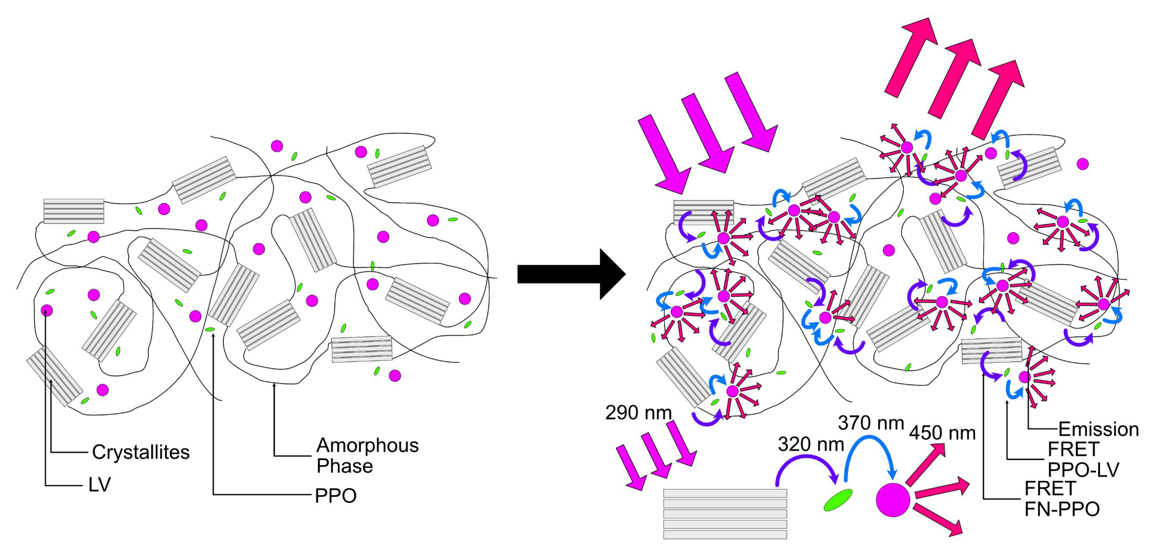
The absorption of the pure fluorophore in FA solution were tested using a Jasco VR-570 UV–Vis spectrophotometer (Jasco, Tokyo, Japan) while the emission with a tested by a Jasco FP-6300 spectrofluorometer (Jasco, Tokyo, Japan) using the wavelength of the maximum absorption.
The fluorescence 3D spectra were acquired with a Jasco FP-6300 spectrofluorometer. The bare fibroin film and the films with PPO were excited between 250 nm and 320 nm and the emission was collected between 270 nm and 450 nm. The films samples with the addition of LV where excited between 250 nm and 500 nm and the emission was collected the emission between 300 nm and 550 nm. The 3D emission was performed by collecting an emission spectrum at a specified excitation wavelength then moving the excitation wavelength of 10 nm and collecting the emission again. All the samples were placed at 45° inside the chamber. The contour plot was reconstructed by R [26] within the Plotly library [27].
Laser Scanning confocal microscopy was performed on the electrospun networks using a Nikon A1 confocal microscope (Nikon, New York, NY, USA). A 405 nm wavelength laser was used fluorescence excitation while emission was collected through a 20×, 0.75 N.A. apochromatic objective and a scanning zoom set at 5× to get a total magnification equal to 100×. To reconstruct the emission spectrum, a spectral detector with a 6 nm amplitude channel was used, for a total of 32 parallel channels spanning the range 405–596 nm. To permit spectra comparison, pinhole aperture (12.8 µm), laser intensity (about 39 mW), PMT gain (43.1%) and dwell time (1 µs/pixel) were set constants for all the samplings.
For better sensitivity, a high resolution and low noise confocal microcopy picture of PPO + LV containing network was collected through a 450/50 nm band-pass filter and a PMT photodetector.
SEM analysis (FE-SEM, Carl-Zeiss Supra 40, Jena, Germany) have been conducted as validation of the proposed technique. The same sample used for the Confocal analysis has been coated with Pt/Pd by sputtering and attached to a stub with the use of carbon tape.
An image analysis was conducted by ImageJ (1.48a, NIH, Bethesda, Rockville, MD, USA) [28], the intensity profile of 70 fibers on both SEM and Confocal images were evaluated and the diameter profiles extrapolated.

3. Results

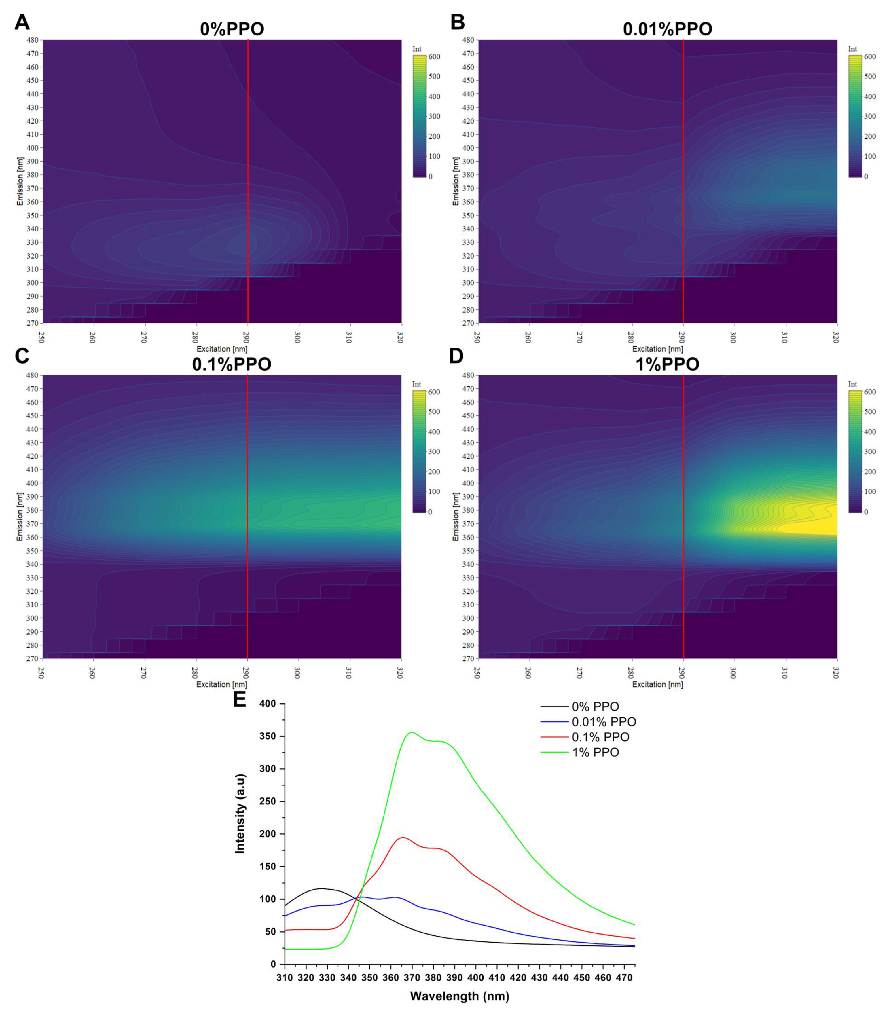
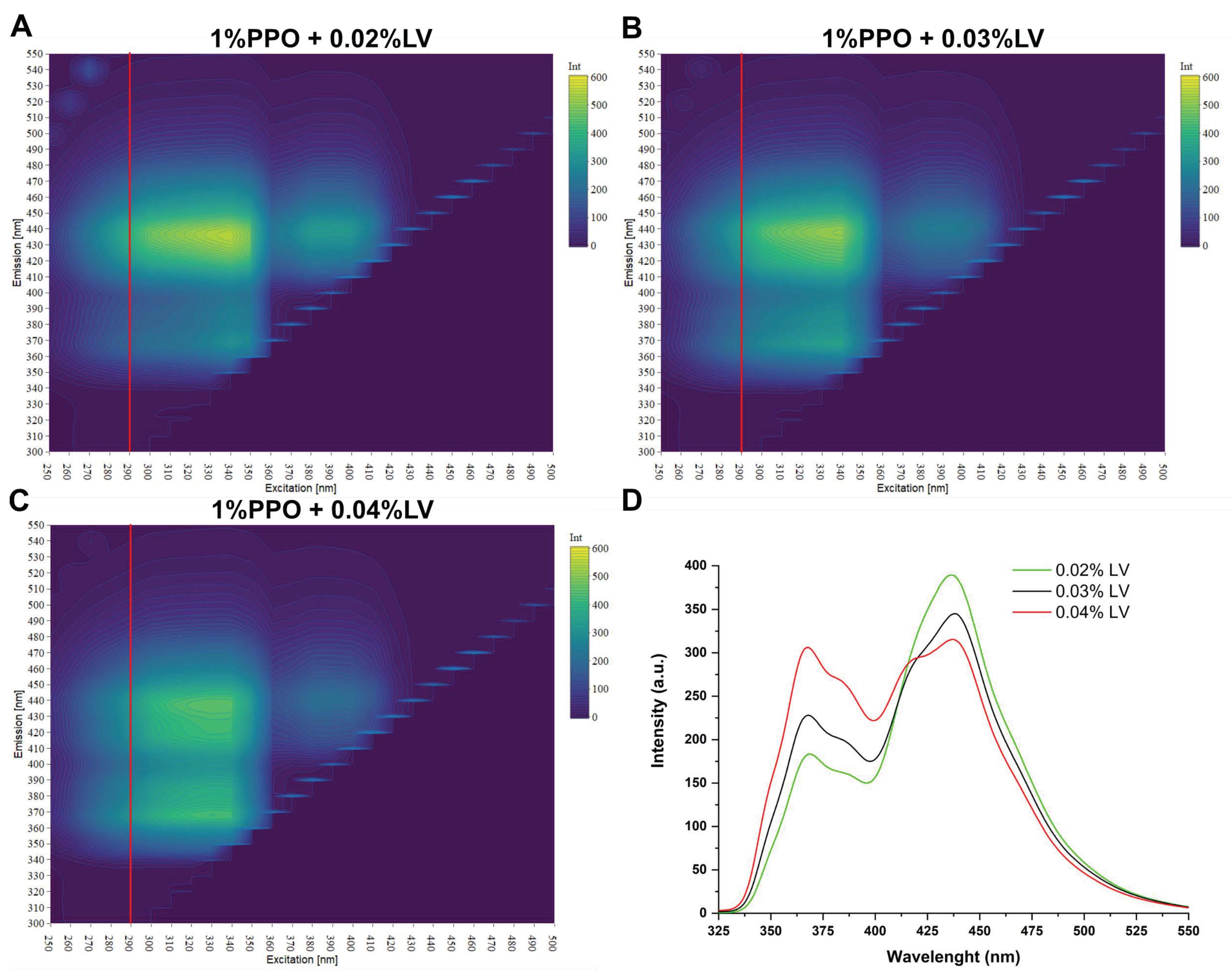
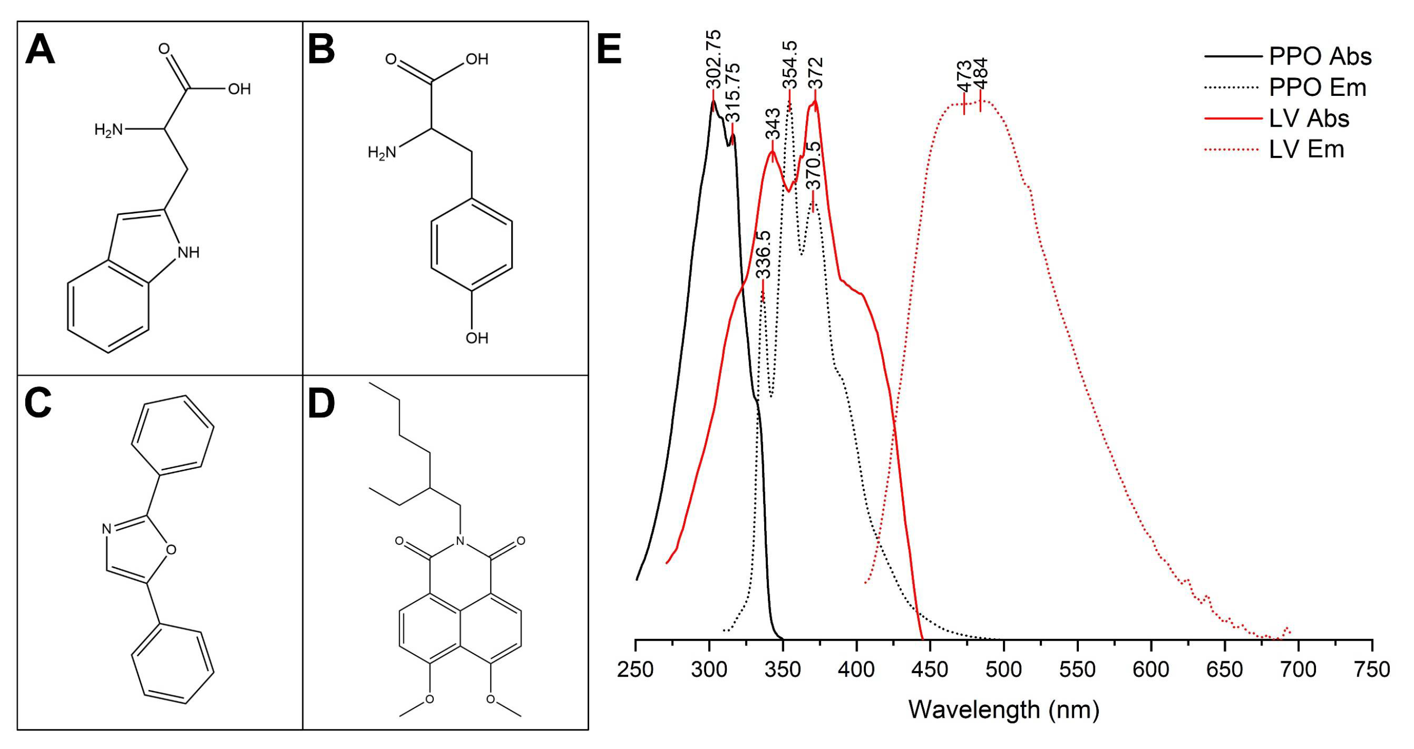
3.1. Emission Spectra

Two amino acids structures responsible for the intrinsic fluorescence of silk fibroin are shown in Figure 1A (tryptophane) and Figure 1B (Tyrosine), while the structure of the fluorophore used are reported in Figure 1C (PPO) and Figure 1D (LV). The absorption spectra superimposed to the emission of the two fluorophores are reported in Figure 1E. The superposition of the emission spectrum of PPO and the absorbance spectrum of LV allowed an efficient energy transfer from these two fluorophores.
The combined effect of tryptophane and tyrosine resulted in an absorption that had its maximum at 290 nm with an emission centered at 330 nm, as reported in Figure 2A in the 3D fluorescence contour plot of pure fibroin. With the increasing in the percentage of added PPO the emission of fibroin was progressively suppressed while the fluorescence emission of PPO increased to a point in which the emission of fibroin not visible and only the large PPO emission peak was present with two maxima centered at 370 nm and 380 nm. This effect was better observed by slicing the surfaces at 290 nm excitation (red lines in Figure 2A–D) and plotting the emission (Figure 2E) where the clear effect is the reduction of the Fibroin emission and a contemporary increase in the PPO emission.
The best result was obtained by the addition of 1% of PPO that was the minimum concentration that allowed to completely suppress the fibroin intrinsic fluorescence, on this formulation we added the LV in an increasing concentration (0.02%, 0.03% and 0.04% respect to the weight of the dissolved fibroin), the results are shown in Figure 3. In this case the trend resulted to be in countertendency respect to the one shown by the fibroin-PPO couple. In fact, with the increasing in amount of LV the energy transfer resulted to be less efficient (moving from Figure 3A–C). This effect was even more evident by slicing the fluorescence surfaces (Figure 3A–C) along the excitation at 290 nm (red lines). The result is shown in Figure 3D, with the increment in the LV percentage the emission of PPO increased, and the emission of LV decreased.

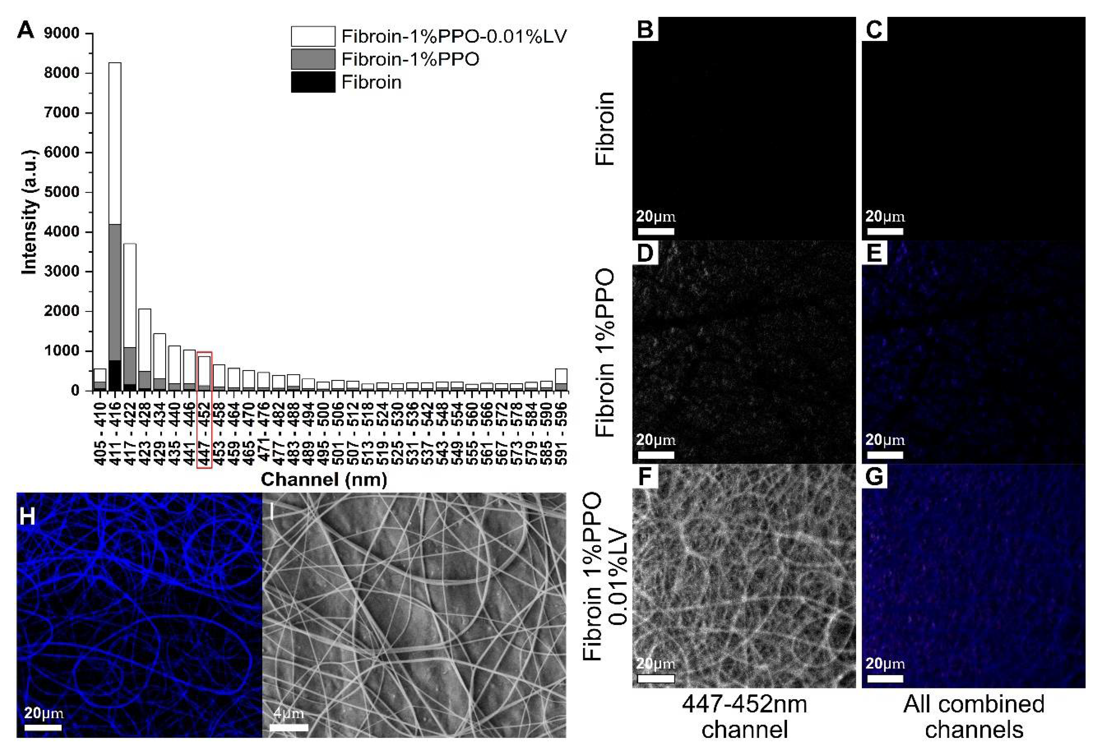
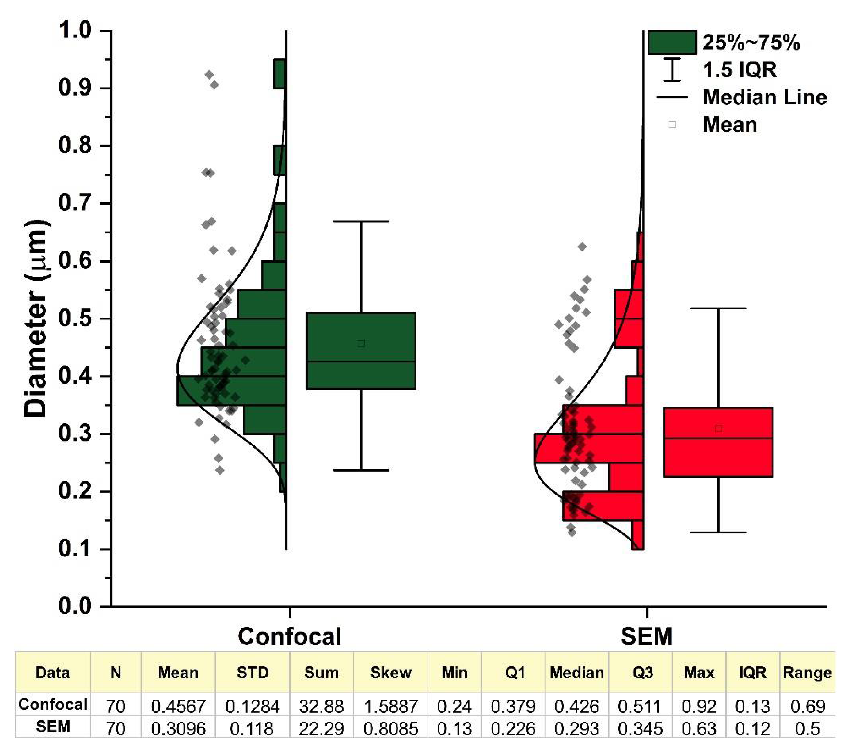
3.2. Confocal Imaging

The confocal study of the prepared samples is shown in Figure 4. Three samples were analyzed, a film produced by the bare protein (Figure 4B,C), one produced with the addition of 1% w/w of PPO, and the last with the addition of 1% of PPO (Figure 4D,E) and 0.02% of LV (Figure 4F–H). We collected one image for each channel for each sample. In this way, we were able to evaluate the fluorescence emission (Figure 4A) at different wavelengths.
The best result in terms of resolution was obtained from the sample obtained by the addition of both PPO and LV selecting the 447–452 nm channel in which LV emits (Figure 4F). In fact, in that condition, the fibers resulted were well recognizable. In the same condition, neither the fibroin sample (Figure 4B) nor the sample with PPO (Figure 4D) gave an acceptable result even if, in the case of the addition of PPO, some of the fibrous structures of the mats were visible. By combining all the channels in a single image, the trend among the samples remained the same (as visible in Figure 4C,E,G).
By the use of a photomultiplier, the image presented in Figure 4H was produced to maximize the resolution of a single slice in the z-stack. In this case, the single fibers that were well distinguishable allowed the determination of the fiber diameter distribution (shown in Figure 4G). As a comparison, we performed the same measurement on a SEM image (Figure 4H). The distributions, visible in Figure 5 within the descriptive statistic, resulted as skewed toward the lower dimeter values in both cases and were well fitted by a log-normal function.
In this case, the standard deviation as well as the interquartile range should be regarded as measures of the distribution width. As can be clearly seen, the distribution obtained had a mean value slightly higher that the value obtained by SEM (0.456 μm vs. 0.310 μm), while the standard deviations were almost comparable (0.128 vs. 118 μm). This could be attributable to the broadening of the diameter due the fluorescence emission and to the fact that, when using SEM, the depth of field was higher, and thus the image included fibers that were on different planes.
However, even if the distributions were different, they largely overlapped, thus, indicating an agreement of the two methodologies. For skewed distributions, as in our case, the median and the interquartile range (IQR) are the correct statistical descriptors. The median and the corresponding IQR, respectively, were 0.426 and 0.13 μm for the confocal distribution and 0.293 and 0.12 μm for the SEM distribution.

4. Discussion

A general scheme of the principle of how this phenomenon worked in our samples is shown in Figure 6. Silk fibroin constitutes two domains: a heavy chain domain that has a highly ordered aminoacidic structure and, consequently, a crystalline secondary structure (mainly β-sheets) [29]. Instead, the light chain has a less ordered secondary structure and is mainly in a random configuration [29]. During the solubilization in LiBr for fibroin and the successive dialysis the β structures were denatured, and then the successive dialysis allowed the elimination of the salt.
The final product was a protein in a water solution with a random secondary structure [30]. The successive rapid cooling in liquid nitrogen and the freeze drying ensured the maintenance of the random structure in the solid phase [10]. Both fluorophores were added to a solution obtained by dissolving silk fibroin in formic acid. The fluorophores were mixed until their complete dissolution to ensure their uniform presence among the material prepared [15,31,32].
The subsequent solvent casting allowed the formation of stable silk films. In fact, formic acid promoted the transition of the secondary structure to the stable β-form (physical crosslinking) [33,34]. This was useful to effectively entrap the fluorophore molecules in a dense structure suitable for the occurrence of the energy transfer. We hypothesized, as previously proven in the literature [35], that, due to the uniformity of the produced films, hydrogen bonding might be present among the amine groups of silk fibroin and the oxygen present in both fluorophores.
FRET occurred between fibroin and PPO and then between PPO and LV. Interestingly, while exiting the tryptophan and tyrosine inside fibroin at 290 nm, the PPO emission increased due to FRET in accordance with the increase of its amount as a percentage. The trend for the PPO-LV couple was a countertendency—the increase of the amount of LV decreased its emission (with an excitation at 290 nm).
This effect could be explained considering that the efficiency also depends on the distance between the acceptor–donor couple, and, in a complex system such as the one that we are studying, it is not straightforward that the solute is evenly dispersed in the matrix, particularly in case of silk fibroin where the light and the heavy chain domains have different affinities [29]. In fact, the heavy chain is mainly hydrophobic, while the light chain is hydrophilic [29].
We hypothesized that a lower amount of LV would ensure a better dispersion of LV and, thus, a lower distance from the PPO molecules and a higher efficiency of the PPO-LV couple. With this composition, we prepared an electro-spun mat and compared it with the same mats produced by the bare fibroin and with fibroin and PPO. Interestingly, the only mat that produced a good outcome with confocal microscopy was the one produced by the addition of both PPO and LV.
On that mats, we were able to perform a deeper morphological analysis using a mild 405 nm laser power level, allowing us to obtain resolute Z-stacks with a 1.6-µm thick confocal plane. The produced fibers might find application as an optical sensor whenever an interaction with biological tissues is required [31,36] as for example in the case of wound healing [37,38] or for visualization purposes both in vitro and in vivo [39,40]. In addition, the proposed methods could be easily coupled with other additive manufacturing techniques [41,42] to produce 3D constructs [43].

5. Conclusions

In this work, we demonstrated the possibility to use silk’s intrinsic fluorescence to image the morphology of a silk fibroin construct. Using the fluorescent amino acids of fibroin in a donor–acceptor couple in which PPO was used as the acceptor, we were able to suppress the fibroin intrinsic fluorescence and transfer the energy to the PPO. With the addition of a second dye (LV), we were able to repeat the same donor–acceptor dynamics, with the result that, when fibroin was exited, the fluorescence emission was due to LV. The energy transfer was confirmed by spectroscopy on fibroin films with the addition of one or both fluorophores.
The best composition of fibroin, PPO, and LV was used to produce fibroin electro spun mats that were observed by confocal microscopy to study the morphology. With the results from FRET, we were able to effectively conduct a morphological analysis and quantify the fiber diameter distribution. The proposed method could be used to produce fluorescent fibers with applications in optical sensing in biological tissues as well as a method to visualize silk constructs whenever other methods are inconvenient. In addition, this method could be applied to other proteins or materials that possess an intrinsic fluorescence.

Author Contributions

A.B., wrote the manuscript, conceived the experiment, prepared part of the samples, and collected and analyzed the data. A.Q., supervised the work and conceived the part related to the fluorescence, D.M., supervised the work prepared the silk fibroin mats collected and analyzed the confocal images. All the authors have edited the final version. All authors have read and agreed to the published version of the manuscript.

Funding

This research received no external funding.

Institutional Review Board Statement

Not applicable.

Informed Consent Statement

Not applicable.

Data Availability Statement

The data presented in this study are available on request from the corresponding author.

Conflicts of Interest

The authors declare no conflict of interest.

References

  1. Yang, Y.J.; Ganbat, D.; Aramwit, P.; Bucciarelli, A.; Chen, J.; Migliaresi, C.; Motta, A. Processing keratin from camel hair and cashmere with ionic liquids. Express Polym. Lett. 2019, 13. [Google Scholar] [CrossRef]
  2. Sultankulov, B.; Berillo, D.; Sultankulova, K.; Tokay, T.; Saparov, A. Progress in the development of chitosan-based biomaterials for tissue engineering and regenerative medicine. Biomolecules 2019, 9, 470. [Google Scholar] [CrossRef] [PubMed] [Green Version]
  3. Sun, J.; Tan, H. Alginate-based biomaterials for regenerative medicine applications. Materials 2013, 6, 1285–1309. [Google Scholar] [CrossRef] [PubMed]
  4. Echave, M.C.; Burgo, L.S.; Pedraz, J.L.; Orive, G. Gelatin as Biomaterial for Tissue Engineering. Curr. Pharm. Des. 2017, 23. [Google Scholar] [CrossRef]
  5. Rockwood, D.N.; Preda, R.C.; Yücel, T.; Wang, X.; Lovett, M.L.; Kaplan, D.L. Materials fabrication from Bombyx mori silk fibroin. Nat. Protoc. 2011, 6, 1612–1631. [Google Scholar] [CrossRef]
  6. Bucciarelli, A.; Greco, G.; Corridori, I.; Pugno, N.M.; Motta, A. A Design of Experiment Rational Optimization of the Degumming Process and Its Impact on the Silk Fibroin Properties. ACS Biomater. Sci. Eng. 2021. [Google Scholar] [CrossRef]
  7. Hwi Cho, H.; Young Been, S.; Youp Kim, W.; Min Choi, J.; Hee Choi, J.; Ui Song, C.; Eun Song, J.; Bucciarelli, A.; Khang, G. Comparative Study on the Effect of the Different Harvesting Sources of Demineralized Bone Particles on the Bone Regeneration of a Composite Gellan Gum Scaffold for Bone Tissue Engineering Applications. ACS Appl. Bio Mater. 2021. [Google Scholar] [CrossRef]
  8. Been, S.; Choi, J.; Cho, H.; Jeon, G.; Song, J.E.; Bucciarelli, A.; Khang, G. Preparation and characterization of a soluble eggshell membrane/agarose composite scaffold with possible applications in cartilage regeneration. J. Tissue Eng. Regen. Med. 2021. [Google Scholar] [CrossRef] [PubMed]
  9. Bucciarelli, A.; Muthukumar, T.; Kim, J.S.; Kim, W.K.; Quaranta, A.; Maniglio, D.; Khang, G.; Motta, A. Preparation and Statistical Characterization of Tunable Porous Sponge Scaffolds using UV Cross-linking of Methacrylate-Modified Silk Fibroin. ACS Biomater. Sci. Eng. 2019, 5, 6374–6388. [Google Scholar] [CrossRef] [PubMed]
  10. Bucciarelli, A.; Chiera, S.; Quaranta, A.; Yadavalli, V.K.; Motta, A.; Maniglio, D. A Thermal-Reflow-Based Low-Temperature, High-Pressure Sintering of Lyophilized Silk Fibroin for the Fast Fabrication of Biosubstrates. Adv. Funct. Mater. 2019, 29, 1901134. [Google Scholar] [CrossRef]
  11. Cho, H.; Bucciarelli, A.; Kim, W.; Jeong, Y.; Kim, N.; Jung, J.; Yoon, S.; Khang, G. Natural Sources and Applications of Demineralized Bone Matrix in the Field of Bone and Cartilage Tissue Engineering. In Bioinspired Biomaterials. Advances in Experimental Medicine and Biology; Chun, H.J., Reis, R.L., Motta, A., Khang, G., Eds.; Springer: Singapore, 2020; pp. 3–14. [Google Scholar]
  12. Zhu, B.; Wang, H.; Leow, W.R.; Cai, Y.; Loh, X.J.; Han, M.Y.; Chen, X. Silk Fibroin for Flexible Electronic Devices. Adv. Mater. 2016, 28, 4250–4265. [Google Scholar] [CrossRef] [PubMed]
  13. Bucciarelli, A.; Pal, R.K.; Maniglio, D.; Quaranta, A.; Mulloni, V.; Motta, A.; Yadavalli, V.K. Fabrication of Nanoscale Patternable Films of Silk Fibroin Using Benign Solvents. Macromol. Mater. Eng. 2017, 302, 1700110. [Google Scholar] [CrossRef]
  14. Bucciarelli, A.; Mulloni, V.; Maniglio, D.; Pal, R.K.; Yadavalli, V.K.; Motta, A.; Quaranta, A. A comparative study of the refractive index of silk protein thin films towards biomaterial based optical devices. Opt. Mater. 2018, 78, 407–414. [Google Scholar] [CrossRef]
  15. Lee, O.J.; Sultan, M.T.; Hong, H.; Lee, Y.J.; Lee, J.S.; Lee, H.; Kim, S.H.; Park, C.H. Recent Advances in Fluorescent Silk Fibroin. Front. Mater. 2020, 7, 50. [Google Scholar] [CrossRef]
  16. Georgakoudi, I.; Tsai, I.; Greiner, C.; Wong, C.; Defelice, J.; Kaplan, D. Intrinsic fluorescence changes associated with the conformational state of silk fibroin in biomaterial matrices. Opt. Express 2007, 15, 1043–1053. [Google Scholar] [CrossRef]
  17. Amirikia, M.; Shariatzadeh, S.M.A.; Jorsaraei, S.G.A.; Mehranjani, M.S. Auto-fluorescence of a silk fibroin-based scaffold and its interference with fluorophores in labeled cells. Eur. Biophys. J. 2018, 47, 573–581. [Google Scholar] [CrossRef] [PubMed]
  18. Paddock, S.W. Principles and practices of laser scanning confocal microscopy. Appl. Biochem. Biotechnol. Part B Mol. Biotechnol. 2000, 16, 127–149. [Google Scholar] [CrossRef]
  19. Hussain, S.A. An Introduction to Fluorescence Resonance Energy Transfer (FRET). Energy 2009, 132, 4. [Google Scholar]
  20. Preus, S.; Wilhelmsson, L.M. Advances in Quantitative FRET-Based Methods for Studying Nucleic Acids. ChemBioChem 2012, 13, 1990–2001. [Google Scholar] [CrossRef] [PubMed]
  21. Sekar, R.B.; Periasamy, A. Fluorescence resonance energy transfer (FRET) microscopy imaging of live cell protein localizations. J. Cell Biol. 2003, 160, 629–633. [Google Scholar] [CrossRef] [Green Version]
  22. Li, H.; Huang, X.X.; Kong, D.M.; Shen, H.X.; Liu, Y. Ultrasensitive, high temperature and ionic strength variation-tolerant Cu2+ fluorescent sensor based on reconstructed Cu2+-dependent DNAzyme/substrate complex. Biosens. Bioelectron. 2013, 42, 225–228. [Google Scholar] [CrossRef]
  23. Jiang, W.; Yang, S.; Lu, W.; Gao, B.; Xu, L.; Sun, X.; Jiang, D.; Xu, H.-J.; Ma, M.; Cao, F. A novel fluorescence “turn off-on” nano-sensor for detecting Cu2+ and Cysteine in living cells. J. Photochem. Photobiol. A Chem. 2018, 362, 14–20. [Google Scholar] [CrossRef]
  24. Danos, L.; Parel, T.; Markvart, T.; Barrioz, V.; Brooks, W.S.M.; Irvine, S.J.C. Increased efficiencies on CdTe solar cells via luminescence down-shifting with excitation energy transfer between dyes. Sol. Energy Mater. Sol. Cells 2012, 98, 486–490. [Google Scholar] [CrossRef]
  25. Quaranta, A.; Carturan, S.; Marchi, T.; Cinausero, M.; Scian, C.; Kravchuk, V.L.; Degerlier, M.; Gramegna, F.; Poggi, M.; Maggioni, G. Doping of Polysiloxane Rubbers for the Production of Organic Scintillators. In Optical Materials; Elsevier B.V.: Amsterdam, The Netherlands, 2010; Volume 32, pp. 1317–1320. [Google Scholar]
  26. Team, R.C. R: A Language and Environment for Statistical Computing; R foundation: Vienna, Austria, 2019. [Google Scholar]
  27. Plotly Technologies Inc. Collaborative Data Science. Available online: https://plot.ly (accessed on 30 March 2021).
  28. Schneider, C.A.; Rasband, W.S.; Eliceri, K.W. NIH Image to ImageJ: 25 years of image analysis. Nat. Methods 2012, 9, 671–675. [Google Scholar] [CrossRef] [PubMed]
  29. Koh, L.D.; Cheng, Y.; Teng, C.P.; Khin, Y.W.; Loh, X.J.; Tee, S.Y.; Low, M.; Ye, E.; Yu, H.D.; Zhang, Y.W.; et al. Structures, mechanical properties and applications of silk fibroin materials. Prog. Polym. Sci. 2015, 46, 86–110. [Google Scholar] [CrossRef]
  30. Wang, H.-Y.Y.; Zhang, Y.-Q.Q. Effect of regeneration of liquid silk fibroin on its structure and characterization. Soft Matter 2013, 9, 138–145. [Google Scholar] [CrossRef]
  31. Min, K.; Kim, S.; Kim, C.G.; Kim, S. Colored and fluorescent nanofibrous silk as a physically transient chemosensor and vitamin deliverer. Sci. Rep. 2017, 7, 1–8. [Google Scholar] [CrossRef] [Green Version]
  32. Myung, S.J.; Kim, H.-S.; Kim, Y.; Chen, P.; Jin, H.-J. Fluorescent silk fibroin nanoparticles prepared using a reverse microemulsion. Macromol. Res. 2008, 16, 604–608. [Google Scholar] [CrossRef]
  33. Um, I.C.; Kweon, H.; Park, Y.H.; Hudson, S. Structural characteristics and properties of the regenerated silk fibroin prepared from formic acid. Int. J. Biol. Macromol. 2001, 29, 91–97. [Google Scholar] [CrossRef]
  34. Um, I.C.; Kweon, H.Y.; Lee, K.G.; Park, Y.H. The role of formic acid in solution stability and crystallization of silk protein polymer. Int. J. Biol. Macromol. 2003, 33, 203–213. [Google Scholar] [CrossRef] [PubMed]
  35. Lin, N.; Meng, Z.; Toh, G.W.; Zhen, Y.; Diao, Y.; Xu, H.; Liu, X.Y. Engineering of fluorescent emission of silk fibroin composite materials by material assembly. Small 2015, 11, 1205–1214. [Google Scholar] [CrossRef] [PubMed]
  36. Pang, L.; Ming, J.; Pan, F.; Ning, X. Fabrication of silk fibroin fluorescent nanofibers via electrospinning. Polymers 2019, 11, 986. [Google Scholar] [CrossRef] [Green Version]
  37. Khalid, A.; Bai, D.; Abraham, A.; Jadhav, A.; Linklater, D.; Matusica, A.; Nguyen, D.; Murdoch, B.J.; Zakhartchouk, N.; Dekiwadia, C.; et al. Electrospun nanodiamond-silk fibroin membranes: A multifunctional platform for biosensing and wound healing applications. ACS Appl. Mater. Interfaces 2020, 12, 48408–48419. [Google Scholar] [CrossRef] [PubMed]
  38. Hadisi, Z.; Farokhi, M.; Bakhsheshi-Rad, H.R.; Jahanshahi, M.; Hasanpour, S.; Pagan, E.; Dolatshahi-Pirouz, A.; Zhang, Y.S.; Kundu, S.C.; Akbari, M. Hyaluronic Acid (HA)-Based Silk Fibroin/Zinc Oxide Core–Shell Electrospun Dressing for Burn Wound Management. Macromol. Biosci. 2020, 20. [Google Scholar] [CrossRef] [PubMed]
  39. Kim, D.W.; Lee, O.J.; Kim, S.W.; Ki, C.S.; Chao, J.R.; Yoo, H.; Yoon, S.-I.; Lee, J.E.; Park, Y.R.; Kweon, H.Y.; et al. Novel fabrication of fluorescent silk utilized in biotechnological and medical applications. Biomaterials 2015, 70, 48–56. [Google Scholar] [CrossRef]
  40. Hu, F.; Lin, N.; Liu, X.Y. Interplay between Light and Functionalized Silk Fibroin and Applications. Iscience 2020, 23, 101035. [Google Scholar] [CrossRef] [PubMed]
  41. Bucciarelli, A.; Reddy Chandraiahgari, C.; Adami, A.; Mulloni, V.; Lorenzelli, L. Precise dot inkjet printing thought multifactorial statistical optimization of the piezoelectric actuator waveform. Flex. Print. Electron. 2020, 5, 045002. [Google Scholar] [CrossRef]
  42. Bucciarelli, A.; Adami, A.; Chandaiahgari, C.R.; Lorenzelli, L. Multivariable Optimization of Inkjet Printing Process of Ag Nanoparticle Ink on Kapton. In Proceedings of the 2020 IEEE International Conference on Flexible and Printable Sensors and Systems (FLEPS), Manchester, UK, 16–19 August 2020; pp. 1–4. [Google Scholar]
  43. Kim, S.H.; Yeon, Y.K.; Lee, J.M.; Chao, J.R.; Lee, Y.J.; Seo, Y.B.; Sultan, M.T.; Lee, O.J.; Lee, J.S.; Yoon, S.I.; et al. Precisely printable and biocompatible silk fibroin bioink for digital light processing 3D printing. Nat. Commun. 2018, 9, 1–14. [Google Scholar] [CrossRef]
Figure 1. Chemical structure of (A) Tryptophan, (B) Tyrosine, (C) 2,5-diphenyloxazole (PPO), and (D) Lumogen F Violet. (E) The absorption and emission spectra of the used fluorophores. The emission of PPO widely overlaps with the absorption of LV. This allows, if the distance between the two fluorophores is small enough, to excite the PPO and observe the LV emission through the non-radiative fluorescence energy transfer.
Electronicmat 02 00015 g001
Figure 2. Fluorescence contour plot of the (A) bare silk fibroin, (B) silk fibroin with the addition of 0.01% of PPO, (C) silk fibroin with the addition of 0.1% of PPO and (D) silk fibroin with the addition of 1% of PPO. (E) Slicing of the fluorescence contour plot at the excitation wavelength of 290 nm. The emission was truncated at 305 nm to cut out the wavelength at which the films were exited (290 nm).
Electronicmat 02 00015 g002
Figure 3. Fluorescence contour plot of the (A) silk fibroin with the addition of 1% of PPO and 0.02% of LV, (B) silk fibroin with the addition of 1% of PPO and 0.03% of LV and (C) silk fibroin with the addition of 1% of PPO and 0.04% of LV. (D) Slicing of the fluorescence contour plot at the excitation wavelength of 290 nm.
Electronicmat 02 00015 g003
Figure 4. Confocal study on silk fibroin mats produced by electrospinning. (A) Fluorescence emission for the collected image divided in 32 emission channels (bandwidth of 5 nm). Maintaining the same condition, the intensity of fibroin with the addition of the single fluorophore (PPO) and the combination of two fluorophores (PPO + LV) was higher than the emission of the silk fibroin. The channel in which the emission of LV occurred (highlighted with a red rectangle) was chosen to produce the images of the fibers shown in (B) for the bare fibroin sample, (D) for the fibroin with 1% of PPO sample, and (F) for the fibroin with 1% of PPO and 0.01% of LV sample. Images of all the combined channels with adjusted intensities for (C) the bare fibroin, (E) fibroin with 1% of PPO, and (G) fibroin with 1% of PPO and 0.01% of LV. The structure of the fibers was well resolved only in the case of the addition of both the fluorophore and the imaging only for the portion of the emission spectra in which the emission of LV occurred. (H) Hi-res image collected by the photomultiplier in for the sample prepared with 1% of PPO and 0.01% of LV. (I) SEM image of the same sample.
Electronicmat 02 00015 g004
Figure 5. Comparison between the diameter distributions obtained by analyzing the confocal hi-res image and a SEM image of the same sample. The descriptive statistic is summarized in the table. The confocal distribution resulted in a slightly higher mean and median diameter in comparison with the SEM distribution. However, the distribution largely overlapped, thus, indicating a good agreement between the methodologies.
Electronicmat 02 00015 g005
Figure 6. Structure of the produced samples and proposed mechanism of emission. The structure formed by solvent casting from formic acid was physically crosslinked due to the transition of the protein to the stable β-sheet structure. Both PPO and LV were entrapped inside the matrix. When the films were irradiated at the excitation wavelength of fibroin, an energy transfer between fibroin and PPO occurred. A second energy transfer occurred between PPO and LV. The visible emission was then the one associated with LV.
Electronicmat 02 00015 g006
Publisher’s Note: MDPI stays neutral with regard to jurisdictional claims in published maps and institutional affiliations.

