Article

Dynamic Modeling and Self-Tuning Fuzzy Skyhook Control of a Metro Vehicle with a Flexible Carbody and Semi-Active Suspension

1
School of Energy and Power Engineering, Lanzhou University of Technology, Lanzhou 730050, China
2
College of Locomotive Vehicle, Nanjing Vocational Institute of Railway Technology, Nanjing 210031, China
3
Key Laboratory of Advanced Pumps, Valves and Fluid Control System of the Ministry of Education, Lanzhou University of Technology, Lanzhou 730050, China
4
Institute of Industrial Technology, CMCU Engineering Co., Ltd., Chongqing 400050, China
5
Zhejiang Ruixing Electromechanical Technology Co., Ltd., Wenzhou 325204, China
6
School of Automation, Xi’an University of Posts and Telecommunications, Xi’an 710121, China
*
Author to whom correspondence should be addressed.
Modelling 2026, 7(4), 170; https://doi.org/10.3390/modelling7040170
Submission received: 19 July 2026 / Revised: 9 August 2026 / Accepted: 12 August 2026 / Published: 17 August 2026

Abstract

Lightweight metro carbodies may exhibit elastic modes within ride-comfort-relevant frequency bands, limiting semi-active suspension controllers tuned offline for nominal conditions. This study proposes a skyhook-based parameter self-tuning fuzzy control (PSTFC) strategy for lateral secondary suspension. Its rule base and membership functions remain fixed, whereas two input quantization factors and one output scaling factor are updated online from the carbody lateral velocity and carbody–bogie relative lateral velocity, enabling state-dependent adaptation without increasing fuzzy-inference complexity. A rigid–flexible coupled multibody model is developed using Craig–Bampton component-mode synthesis and validated against field vibration measurements from a Type-A metro lead car. The controller is evaluated using ADAMS/Rail–MATLAB co-simulation, with robustness examined through repeated stochastic simulations and variations in vehicle speed, passenger load, track-irregularity intensity, and suspension parameters. The flexible model reproduces the measured location-dependent spectral characteristics more accurately than the rigid-carbody model. Under nominal conditions, PSTFC reduces the rear-carbody lateral-acceleration RMS from 0.1341 to 0.1015 m/s2 and the Sperling ride comfort index from 1.5485 to 1.2864, corresponding to improvements of 24.3% and 16.9% over passive suspension. Relative to fixed-parameter fuzzy skyhook control, the two indicators are further reduced by 5.8% and 4.7%, respectively. The improvement persists across the investigated off-nominal conditions without controller retuning. These results demonstrate that state-dependent parameter scaling improves the adaptability of fuzzy skyhook control while retaining a compact inference structure, providing a computationally tractable approach to flexible-carbody vibration suppression.

1. Introduction

With the rapid development of urban rail transit systems, increasing demands have been placed on metro vehicles in terms of operational efficiency, structural lightweighting, running stability, and ride comfort. Lightweight carbody design can effectively reduce vehicle mass and energy consumption; however, the associated reduction in structural stiffness increases the contribution of elastic deformation to vehicle vibration responses [1,2,3]. When excitation frequencies induced by wheel–rail interactions approach the natural frequencies of the carbody structure, flexible modes may be excited, leading to intensified local vibrations and deterioration in running stability and ride comfort. Therefore, appropriately accounting for carbody structural flexibility in vehicle dynamic analysis and suspension-control design has become an important issue for improving the accuracy of vibration prediction and control in metro vehicles [3,4].
Vehicle vibrations are primarily transmitted and attenuated through the suspension system. Compared with conventional passive suspensions, active and semi-active suspensions can adjust their dynamic characteristics in response to variations in vehicle motion and external excitation, thereby providing enhanced vibration-control capability [5,6]. Semi-active suspension systems, in particular, offer a favorable compromise among vibration attenuation, energy consumption, fail-safe capability, and implementation complexity, and have therefore attracted considerable attention in railway vehicle applications [7]. Various control strategies have been investigated for semi-active suspensions, including skyhook control [8,9], proportional–integral–derivative (PID) control [10], linear quadratic regulator (LQR) control [11], sliding-mode control (SMC) [12], and fuzzy logic control (FLC) [13]. To overcome the limitations of individual control methods in terms of nonlinear adaptability, control smoothness, and parameter robustness, hybrid strategies integrating complementary control mechanisms have also received increasing attention [14,15,16,17,18].
Among these approaches, fuzzy skyhook control combines the physically interpretable principle of skyhook damping with the nonlinear mapping capability of fuzzy inference, making it particularly attractive for semi-active vehicle suspension systems [19,20,21]. By introducing fuzzy inference into the control process, abrupt variations in the control output associated with damping-state switching can be alleviated, while the resulting control commands can be readily implemented using variable-damping devices such as magnetorheological dampers [19,22]. Fuzzy skyhook control has also been applied to semi-active suspensions of metro vehicles with flexible carbodies, demonstrating its potential for carbody vibration suppression [21]. Nevertheless, the input quantization factors and output scaling factors of such controllers are generally determined offline for prescribed nominal conditions. Once these parameters are fixed, the scaling relationship between the vehicle vibration states and the fuzzy-control output remains essentially unchanged. Consequently, when the vibration amplitude or dynamic response characteristics vary, fixed scaling parameters may be unable to appropriately coordinate input sensitivity and control-output intensity across different vibration states, thereby limiting the state adaptability of the controller [19,21,23].
Adaptive fuzzy control and parameter self-tuning provide potential means of overcoming this limitation by adjusting controller parameters according to variations in system states [15,24]. However, increasing the degrees of freedom for online adaptation can also increase controller-design complexity and real-time computational burden, particularly when membership functions, fuzzy universes, or rule bases are dynamically updated. This issue becomes especially relevant for metro vehicles with flexible carbodies, for which suspension control is required to suppress not only the overall rigid-body motion of the carbody but also spatially distributed vibrations associated with structural deformation. Although flexible-carbody dynamics, fuzzy skyhook control, and adaptive suspension control have been extensively investigated from different perspectives [3,4,15,22,25,26,27,28], further investigation is required to establish a computationally simple and physically interpretable parameter-adjustment mechanism that directly relates flexible-carbody vibration states to the online tuning of fuzzy skyhook control parameters. The key issue is therefore not merely to introduce adaptation into fuzzy skyhook control, but to establish a physically meaningful relationship between the instantaneous vibration state and the controller scaling parameters while maintaining a suitable balance between control capability and real-time implementation complexity.
To address this issue, a skyhook parameter self-tuning fuzzy control (PSTFC) strategy is proposed for lateral vibration suppression of metro vehicles with flexible carbodies. The carbody lateral velocity and the relative lateral velocity between the carbody and bogie are employed to characterize the instantaneous vibration state, based on which the input quantization factors k e 1 and k e 2 and the output scaling factor k u   are adjusted online. This mechanism enables the controller to coordinate its input sensitivity and control-output intensity according to variations in the vibration state. In contrast to conventional fuzzy skyhook control with fixed scaling parameters, the proposed PSTFC introduces state-dependent online adjustment of the control scaling factors. Meanwhile, unlike adaptive schemes that require online reconstruction of membership functions or fuzzy rules, the basic membership functions and rule base remain unchanged during operation, thereby providing enhanced state adaptability while retaining a relatively simple control structure. To evaluate the proposed strategy, a rigid–flexible coupled dynamic model of the metro vehicle is first established and validated against field vibration measurements. The key PSTFC parameters are subsequently calibrated and subjected to sensitivity analysis, after which an ADAMS/Rail–MATLAB (ADAMS 2005R2, MATLAB R2023b) co-simulation framework is employed to comprehensively assess the semi-active vibration-control performance in terms of vibration responses at different carbody locations, frequency-domain characteristics, and vehicle dynamic performance.

2. Rigid–Flexible Coupled Dynamic Modeling and Experimental Validation

2.1. Theoretical Framework of Rigid–Flexible Coupled Modeling for Metro Vehicles

In flexible carbody modeling, a point p on the flexible carbody in the global coordinate system is first defined, which can be expressed by Equation (1) [25]:
p T = P x   P y   P z   α   β   γ   τ i T = P T   H T   τ T
where Px, Py, Pz are the three coordinate components of the local coordinate system in the global reference frame; α, β, γ represent the Euler angles of the local coordinate system relative to the global system; τi denotes the i-th modal shape corresponding to the selected modal order; P and H are the vector sets of the respective coordinate systems; and τ represents the collection of modal shape vectors.
When the carbody is discretized into j elements, the total kinetic energy can be expressed as Equation (2):
E j = 1 2 V j ρ j p j T p j d V j = 1 2 p ˙ j T M j   p ˙ j
where ρj and Vj are the density and volume of element j, respectively, and Mj represents the mass matrix of the flexible body element.
The dynamic equation of the flexible carbody can be formulated as Equation (3):
M p ¨ + M ¨ p 1 2 M p p ˙ T p ˙ + K σ + f g + C p ˙ + H P T λ = R
and rewritten as
M p ¨ + C p ˙ + K p = F T
where M, C, and K are the mass, damping, and stiffness matrices of the flexible carbody, respectively; fg denotes the gravitational force; λ is the Lagrange multiplier associated with the constraint equation T; R represents the generalized force matrix; and FT is the external force matrix.
Currently, the mainstream approach for dynamic simulation analysis adopts the improved Craig–Bampton method [26], which effectively addresses elastic deformation and internal modal stress computation in rigid–flexible coupled systems under static and dynamic loading conditions. Through relevant interfaces, the extracted modal information can be integrated into the multi-body vehicle model, forming a rigid–flexible coupled dynamic model of the vehicle that incorporates flexible deformations, thereby enabling corresponding dynamic simulations.

2.2. Rigid–Flexible Coupled Dynamic Modeling Considering Carbody Flexibility

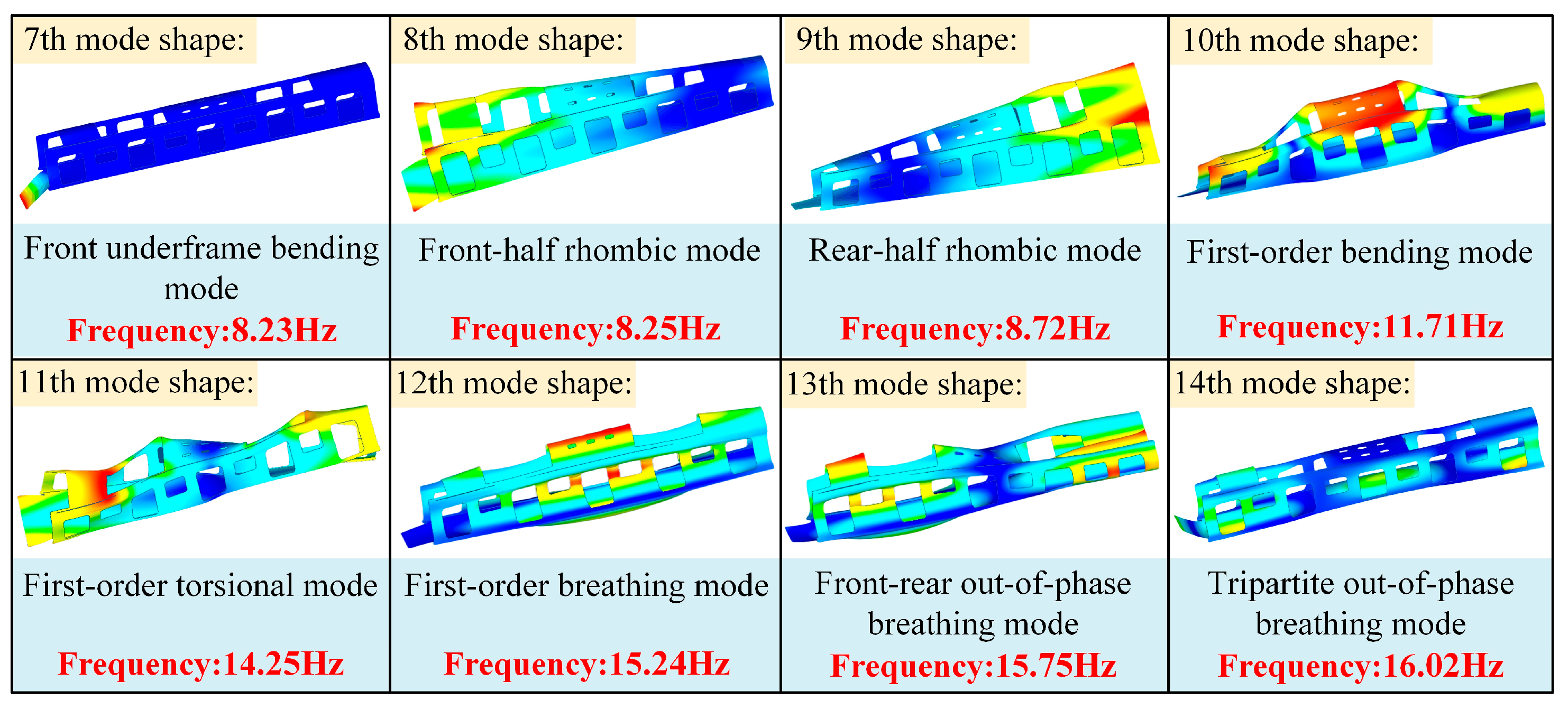
A lead car of a Type-A metro vehicle is selected as the research object. The lead car retains the principal dynamic subsystems governing vehicle lateral vibration, particularly the carbody–bogie coupling through the secondary lateral suspension, which constitutes the primary control path considered in this study. Moreover, the cab structure and nonuniform equipment arrangement introduce spatial variations in carbody mass and stiffness, providing a representative engineering configuration for investigating flexible vibration and its interaction with semi-active suspension control. To ensure computational efficiency while preserving dynamic accuracy, structural components that have negligible influence on the overall vibration characteristics are appropriately simplified. A detailed three-dimensional carbody model is then established, and finite element meshing is performed using HyperMesh software. To investigate the structural vibration characteristics, a modal analysis is conducted. The first six rigid-body modes are excluded, and the 7th to 14th modes are selected for evaluation [27]. The corresponding modal frequencies and mode shapes are summarized in Figure 1.
As shown in Figure 1, the 7th-order mode primarily reflects deformation of the front underframe of the carbody. The 8th-order mode is characterized by a diamond-shaped distortion in the front half of the carbody, while the 9th-order mode exhibits a similar diamond-shaped distortion in the rear half. The 10th-order mode involves pronounced bending deformation across the front, middle, and rear sections of the roof structure. The 11th-order mode mainly represents a global torsional deformation of the carbody. The 12th-order mode corresponds to an overall breathing vibration of the carbody. In the 13th-order mode, the front and rear sections undergo breathing motion in opposite phases. The 14th-order mode displays breathing vibrations involving the front, middle, and rear sections of the carbody, with the middle section vibrating in antiphase with the front and rear ends.
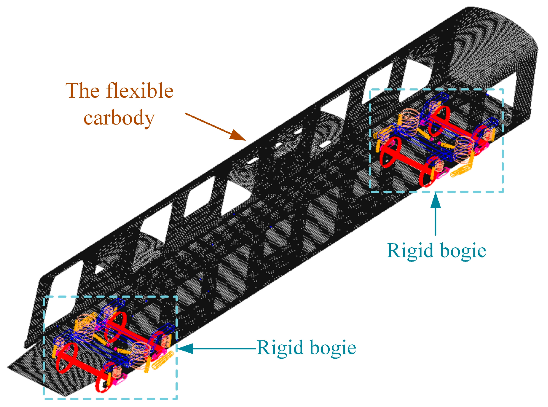
The modal analysis results of the carbody are exported in the form of a modal neutral file and imported into ADAMS/Rail for further simulation. The rigid–flexible coupled dynamic analysis focuses primarily on the flexible modes of the carbody structure [28]. Since the first six modes correspond to rigid-body motions, they are excluded from the flexible subsystem. The flexible carbody model is then assembled with the bogies to construct a complete rigid–flexible coupled metro vehicle dynamic model, as illustrated in Figure 2.

2.3. Field-Test Conditions and Validation of the Rigid–Flexible Coupled Model

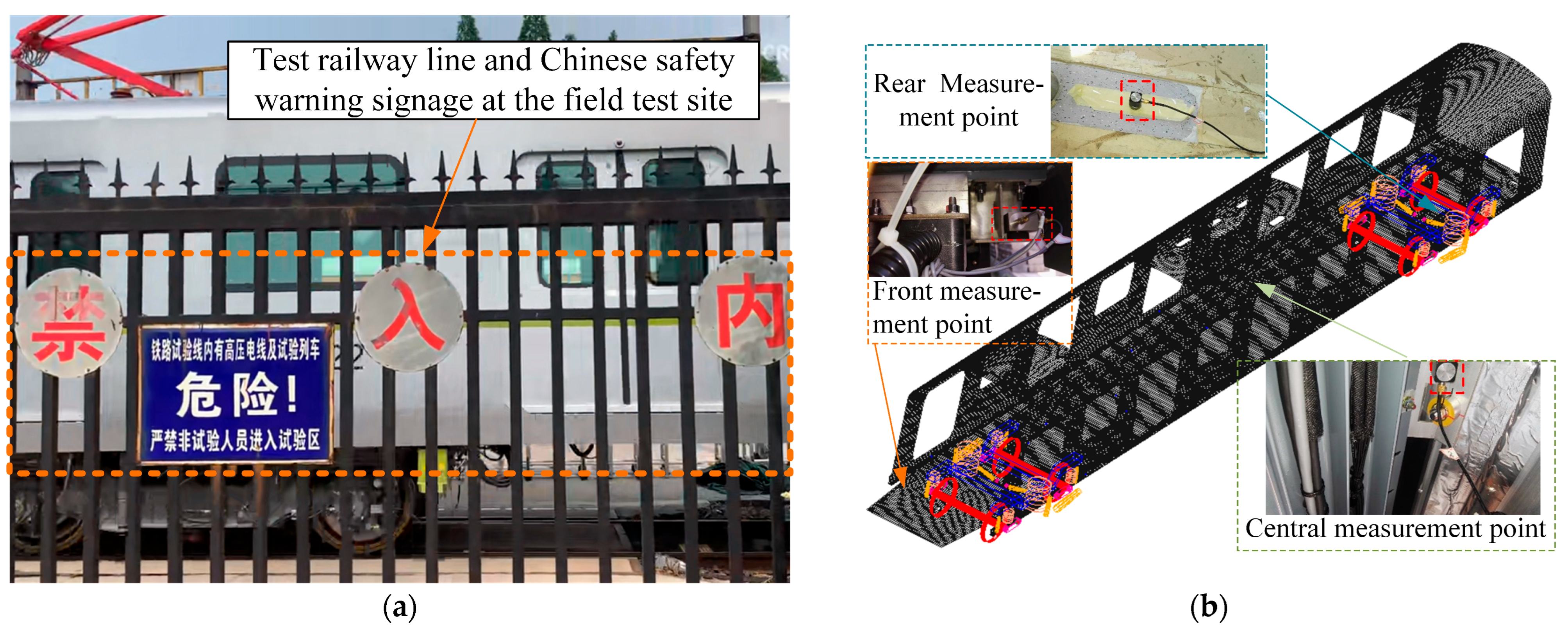
To validate the capability of the established rigid–flexible coupled dynamic model to reproduce the vibration responses of the metro carbody and to further assess the necessity of incorporating structural flexibility, field running tests were conducted using a Type-A metro vehicle on a dedicated CRRC test track. The test track is shown in Figure 3a. The measured lateral vibration responses of the carbody were subsequently compared with the numerical results obtained from both the rigid-carbody and rigid–flexible coupled models.
To minimize the additional effects of track curvature and longitudinal gradient on the lateral vibration responses of the vehicle, an approximately level tangent section with a total available length of approximately 1.1 km was selected. The test section consisted of a ballasted track with a standard gauge of 1435 mm and a longitudinal gradient of less than 2‰. During each test run, the vehicle accelerated from standstill to 80 km/h at approximately 1.0 m/s2, maintained a speed of approximately 80 km/h for about 2s, and subsequently decelerated to a complete stop at approximately 1.0 m/s2. Based on this nominal operating profile, the travel distance required to complete one acceleration–short constant-speed–deceleration cycle was approximately 560 m. Therefore, the selected 1.1-km tangent section provided sufficient longitudinal margin for vehicle acceleration, braking, and stopping. The main field-test conditions are summarized in Table 1.
To further characterize the track excitation conditions of the test section, the track geometric irregularities were measured in the field, and their spatial power spectral densities (PSDs) were obtained from the distance-domain measurement data. The results showed that, over the spatial-frequency range considered in this study, the measured track irregularities exhibited good agreement with the German high-disturbance track irregularity spectrum in terms of both spectral shape and overall excitation level. To further quantify this agreement, the analytical form of the German track irregularity spectrum was calculated from the measured PSDs to obtain equivalent spectral parameters. The resulting characteristic spatial frequencies and roughness coefficients are compared with the reference parameters of the German high-disturbance spectrum in Table 2.
As shown in Table 2, the equivalent spectral parameters calculated from the measured track irregularities are comparable to the reference parameters of the German high-disturbance spectrum. For the fitted results listed in the table, the absolute relative differences of all parameters are below 5%, indicating that the German high-disturbance spectrum provides a reasonable representation of the stochastic track-excitation level of the test line.
According to the speed classification of the German track irregularity spectra, the high-disturbance spectrum is applicable to lines with operating speeds below 250 km/h, whereas the low-disturbance spectrum is primarily intended for operating speeds of 250 km/h and above. The maximum test speed of 80 km/h in the present study therefore lies within the applicable speed range of the high-disturbance spectrum. More importantly, the measured track irregularities exhibit spectral characteristics and excitation levels comparable to those of the high-disturbance spectrum. Therefore, the use of the German high-disturbance track irregularity spectrum in the subsequent dynamic simulations is not based on a “high-speed railway” operating scenario, but rather on both its applicable speed range and its consistency with the measured track conditions. The German track irregularity spectra and the corresponding parameters can be found in Zhai [29].
To characterize the vibration responses at different longitudinal positions of the flexible carbody, three lateral acceleration measurement points were arranged at the front, middle, and rear sections of the carbody. The front measurement point was located at the rivet mounting position of the front underframe; the middle measurement point was located at the left-side roof-hanger bolt in the middle section of the carbody; and the rear measurement point was located on the carbody floor above the rear bogie, with a lateral offset of 1 m from the longitudinal centerline of the carbody. The test arrangement and subsequent vehicle dynamic-performance evaluation were conducted with reference to GB/T 5599–2019. The locations of the three measurement points and the field-test setup are shown in Figure 3b.
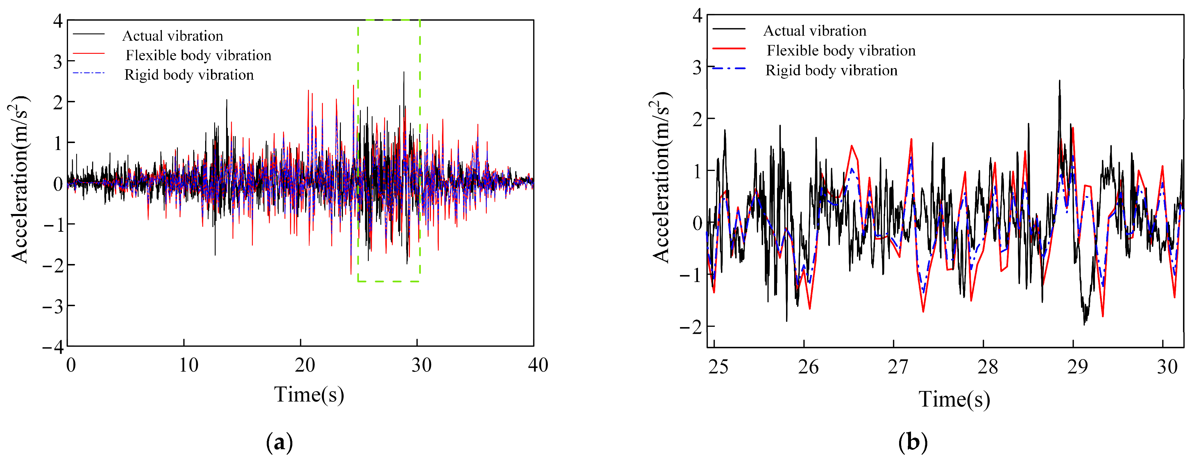
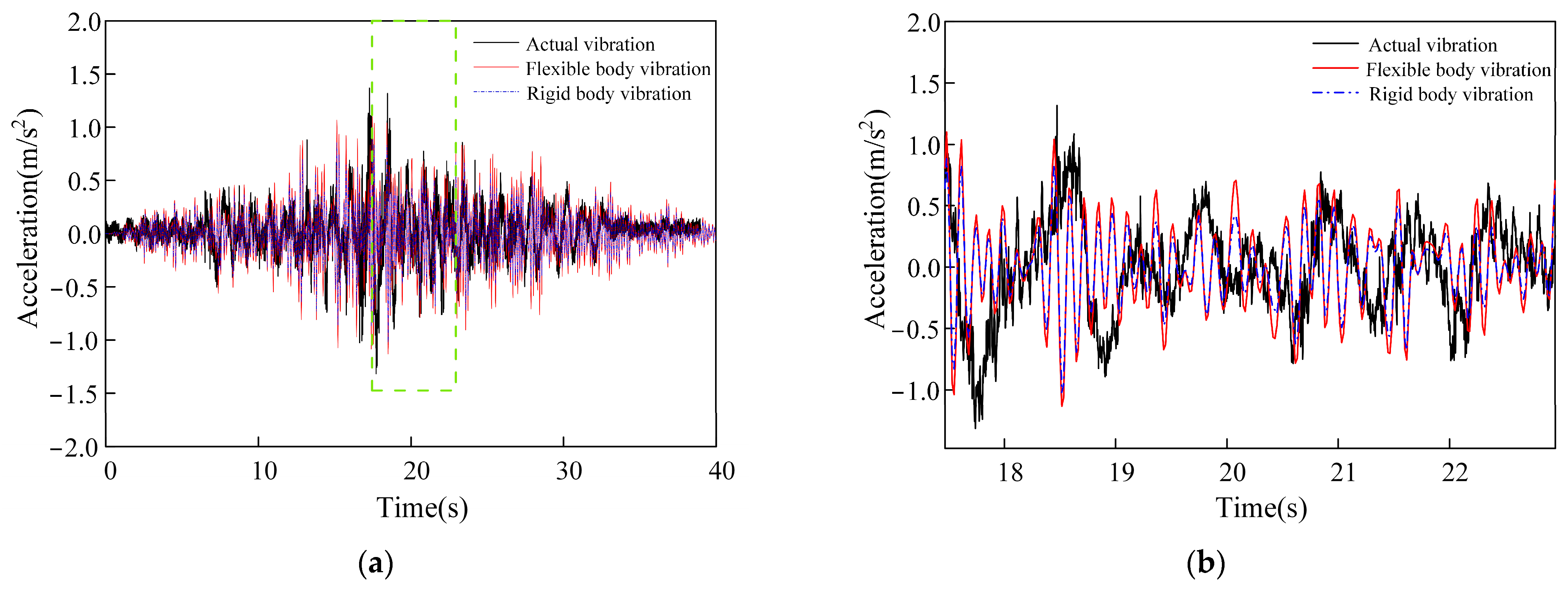
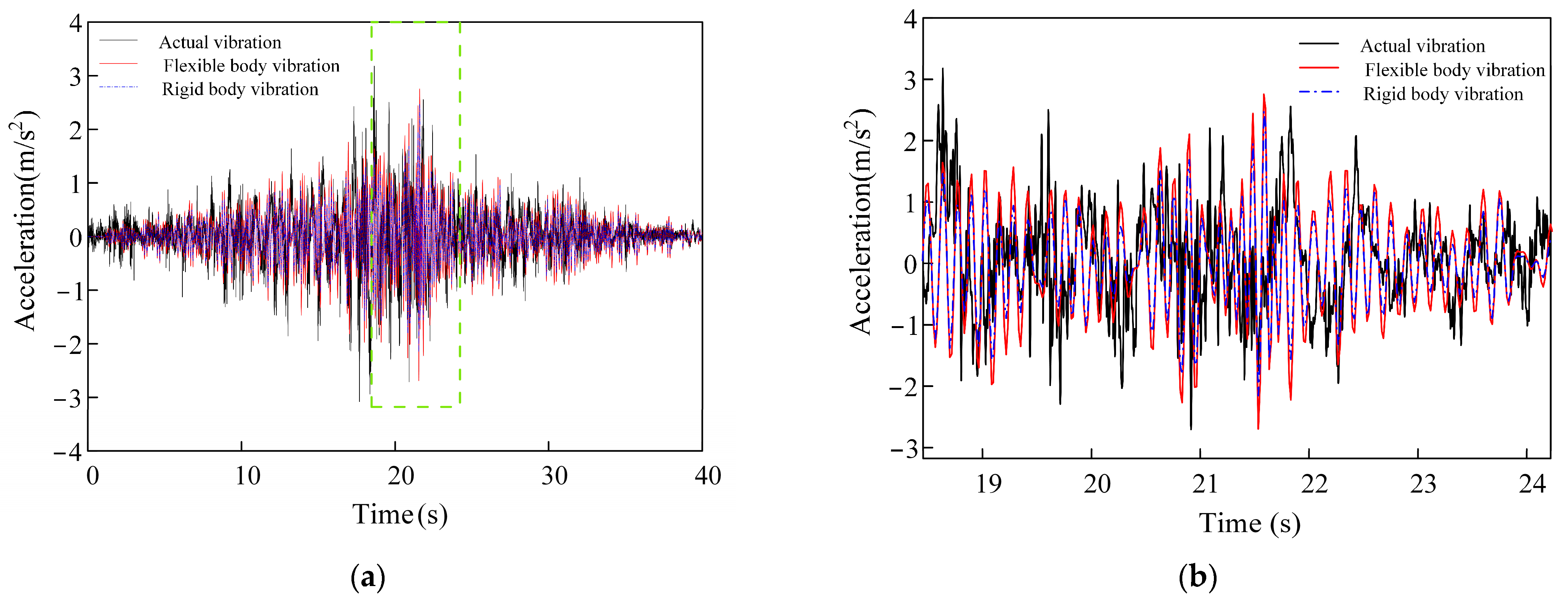
For model validation, the rigid-carbody and rigid–flexible coupled models were evaluated using identical vehicle parameters, nominal operating profiles, and track-excitation levels to ensure a consistent basis for comparison. Because track irregularity is inherently stochastic, phase-by-phase agreement between the simulated and measured acceleration time histories is not expected when a statistically equivalent track spectrum is used as the numerical excitation. Accordingly, model validation focuses primarily on the amplitude and variation characteristics of the time-domain responses, together with the dominant frequencies, spectral-peak locations, and vibration-energy distributions in the PSDs. The lateral acceleration responses obtained from the rigid–flexible coupled model, rigid-carbody model, and field measurements at the front, middle, and rear sections of the carbody are compared in Figure 4, Figure 5 and Figure 6.
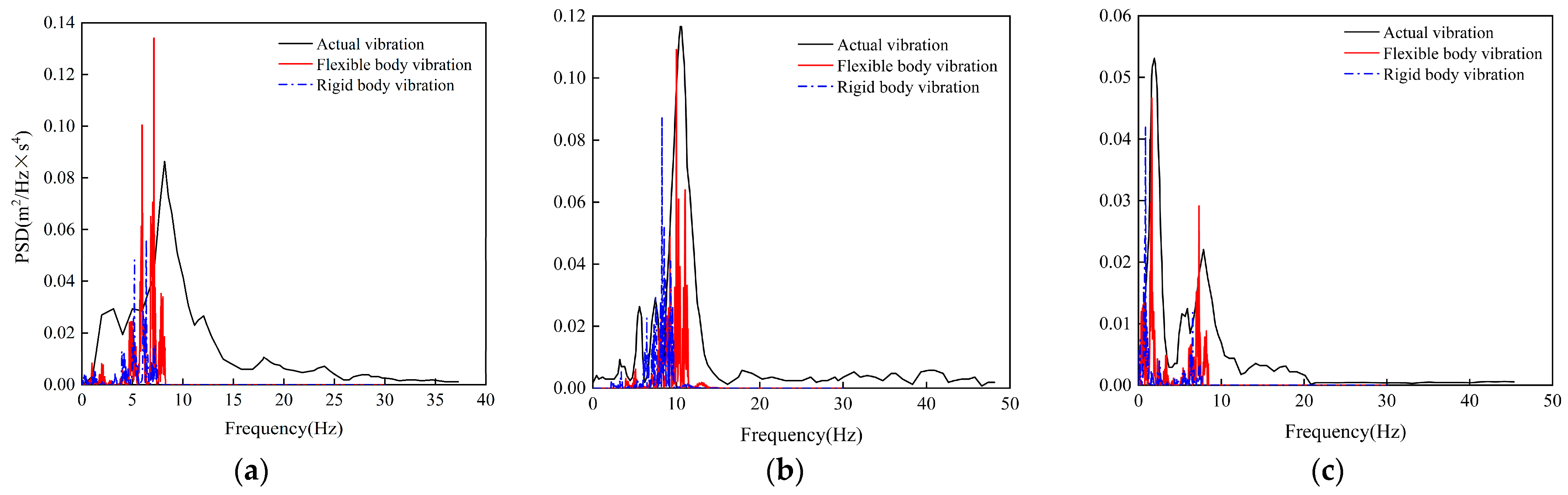
To further investigate the frequency-domain characteristics of metro carbody vibrations and to evaluate the advantages of flexible modeling in capturing dynamic behavior, a power spectral density (PSD) analysis was performed on the simulated and experimentally measured lateral accelerations at the front, middle, and rear sections of the carbody. The results are presented in Figure 7.
As shown in Figure 7, the PSD curves at different measurement points along the carbody exhibit notable differences in both frequency distribution and spectral amplitude.
At the front section of the carbody (Figure 7a), a distinct resonance peak is observed near 8.1 Hz in the measured lateral acceleration. This frequency corresponds closely to the local modal frequencies of front underframe bending (f = 8.23 Hz) and rhomboidal distortion of the front carbody (f = 8.25 Hz).
In the middle section (Figure 7b), the dominant resonance peak in the measured signal appears around 10.1 Hz, which is close to the frequency of the tripartite out-of-phase roof bending mode (f = 11.1 Hz).
At the rear section (Figure 7c), two significant spectral peaks are observed at 2.2 Hz and 8.5 Hz. The peak at 8.5 Hz closely matches the rear-end rhombic mode (f = 8.72 Hz), while the 2.2 Hz peak suggests that a portion of the vibrational energy is concentrated in the low-frequency domain, likely associated with rigid structural responses.
Across all three locations—front, middle, and rear—the flexible carbody model demonstrates better agreement with the measured PSD profiles than the rigid-body model, in terms of both peak frequency locations and spectral amplitudes. In summary, the flexible carbody model shows superior numerical performance in both time-domain and frequency-domain responses across all measurement points. Its advantages are particularly prominent in frequency bands dominated by structural flexibility, validating the necessity of incorporating flexible structural characteristics in dynamic modeling of railway vehicles.

3. Semi-Active Suspension System Control

3.1. Skyhook-Parameter Self-Tuning Fuzzy Control Strategy

In practical operations, the ideal skyhook control cannot be implemented directly, as the damping force can only be provided by a damper placed between the carbody and the bogie. Hence, an actual variable damping coefficient is introduced to approximate the skyhook damping behavior, as expressed in Equation (5):
C = C s k y y ˙ c y ˙ c y ˙ t y ˙ c y ˙ c y ˙ t > 0 0 y ˙ c y ˙ c y ˙ t 0
where c denotes the lateral velocity of the carbody and (ct) is the relative velocity between the carbody and the bogie frame. When (c − ẏt)→0, the resulting damping coefficient tends toward ∞. Since the damping force output by physical dampers is limited, the actual damper can only approximate the ideal skyhook behavior to some extent. Therefore, in engineering applications, the continuous control logic is typically simplified into a binary switching control strategy, formulated in Equation (6):
C s k y = C max         y ˙ c y ˙ c y ˙ t > 0 C min         y ˙ c y ˙ c y ˙ t 0
As shown in Equation (6), when the carbody velocity c and the relative velocity ct have the same direction, the controller applies the maximum damping value; when their directions are opposite, the minimum damping is applied. This binary switching behavior leads to frequent transitions between damper states, and the resulting abrupt changes in damping force may induce chattering in the suspension system, severely limiting control performance.
To address this limitation, fuzzy control principles are introduced to smooth the damping variation. When c(ct) > 0, i.e., the carbody velocity and relative velocity are directionally consistent, a fuzzy logic system is employed to divide the activated damping output into multiple graded levels rather than applying a single fixed value. This approach enables the formation of a skyhook fuzzy hybrid control scheme, which mitigates the impact caused by instantaneous damping jumps from minimum to maximum levels. As a result, it significantly improves the damping smoothness and overall vibration suppression performance of the semi-active suspension system. The fuzzy control law based on the skyhook damping principle is formulated in Equation (7):
C ˜ s y = C max y ˙ c y ˙ c y ˙ t > 0 c s k y y ˙ c y ˙ c y ˙ t C max P A | P B | P C | P D | P E | P F | P G y ˙ c y ˙ c y ˙ t > 0 C min < c s k y y ˙ c y ˙ c y ˙ t < C max C min y ˙ c y ˙ c y ˙ t 0 c s k y y ˙ c y ˙ c y ˙ t C min
where the fuzzy subsets (PA|PB|PC|PD|PE|PF|PG) denote seven discrete levels of damping force, into which the damper output is classified through fuzzy inference.
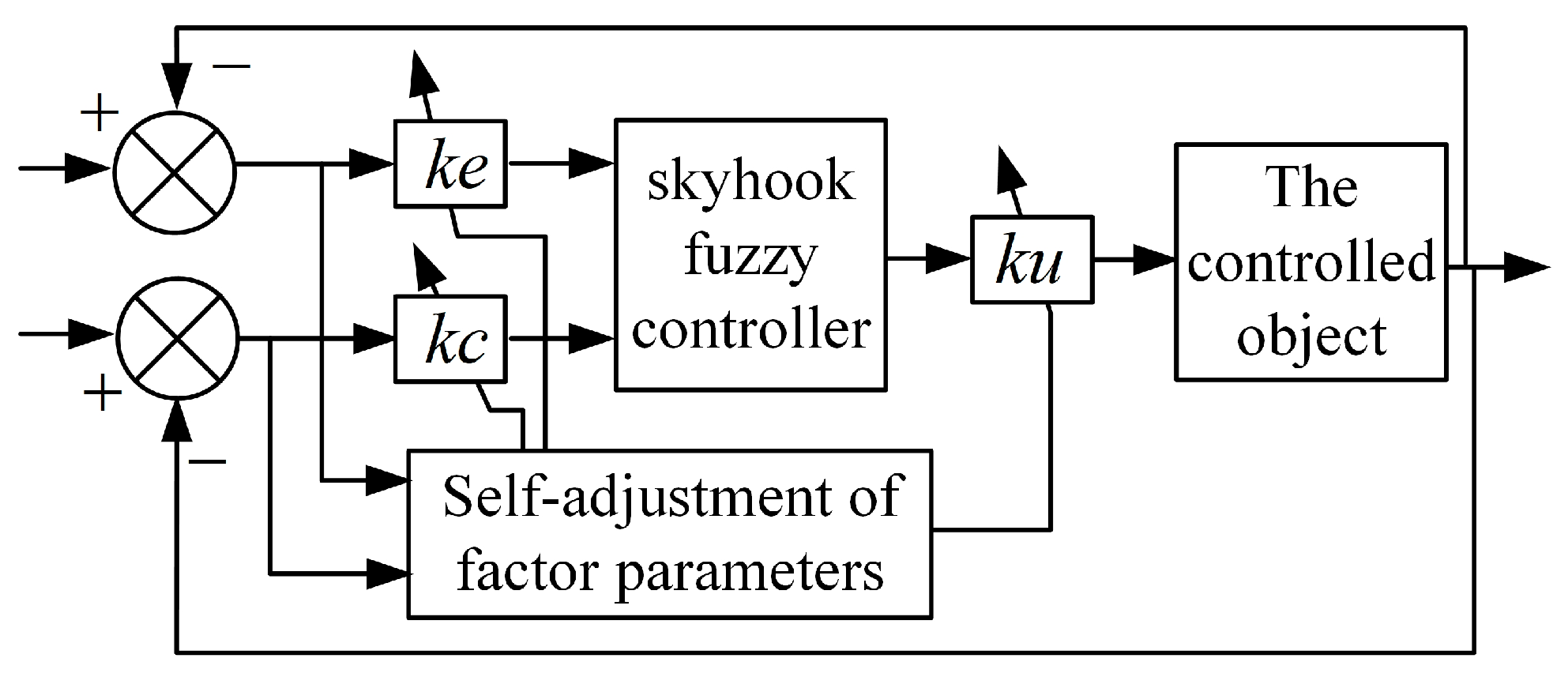
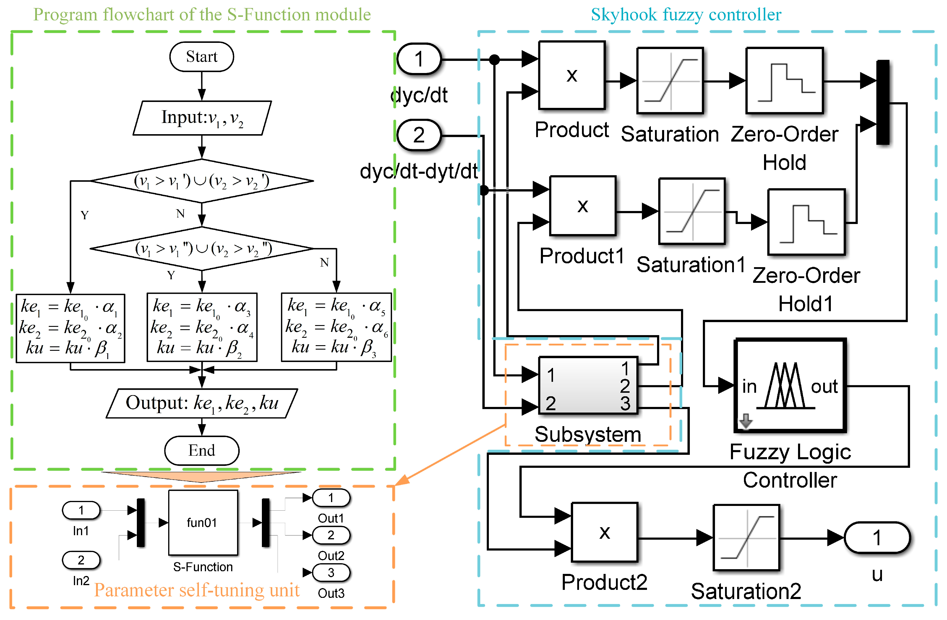
In the aforementioned fuzzy control strategy, the quantization factors and proportional factors are typically preset and remain constant throughout operation. These parameters are usually tuned offline to ensure overall system performance under nominal conditions, which limits the controller’s adaptability to real-time variations. To address this limitation, the present work proposes an enhancement to the skyhook fuzzy control by introducing a parameter self-tuning mechanism. Based on two real-time input variables—the carbody velocity c and the relative velocity between the carbody and bogie ct —the control system dynamically adjusts both the quantization and proportional factors to improve responsiveness and adaptability. The complete structure of the skyhook-PSTFC Strategy is illustrated in Figure 8.
As illustrated in Figure 8, conventional skyhook fuzzy controllers generally employ fixed input quantization factors and output scaling factors, which remain unchanged once they have been tuned offline. When the carbody vibration state, excitation intensity, or suspension operating condition deviates from the nominal design condition, such fixed scaling may lead to insufficient utilization or excessive amplification of the fuzzy input domains, thereby limiting the controller’s capability to accommodate non-stationary vibration responses. To overcome this limitation, a state-dependent online parameter-tuning mechanism is incorporated into the conventional skyhook fuzzy control framework. Specifically, two input quantization factors, k e 1 and k e 2 , together with the output scaling factor k u , are adjusted online according to the instantaneous vibration state of the carbody, thereby enabling state-dependent rescaling of the fuzzy controller.
The lateral carbody velocity and the relative lateral velocity between the carbody and bogie frame are selected as the state variables for parameter scheduling and are defined as
v 1 = y ˙ c
and
v 2 = y ˙ c y ˙ t
respectively. Here, v1 characterizes the absolute lateral vibration state of the carbody, whereas v2 reflects the relative motion across the secondary suspension. These two variables therefore provide complementary information regarding the carbody response and the dynamic state of the secondary lateral suspension. It should be emphasized that v1 denotes the lateral vibration velocity of the carbody rather than the vehicle operating speed along the track.
Following quantization, the normalized inputs to the fuzzy inference system are expressed as
e 1 = k e 1 v 1 , e 2 = k e 2 v 2
After fuzzy inference, the normalized output is mapped to the physical control command through the output scaling factor:
u = k u u f
where k e 1 and k e 2 determine the mapping scales from the physical state variables to the fuzzy input domains, whereas k u determines the scaling from the normalized fuzzy output to the physical control command. Consequently, the effective input resolution and output intensity of the controller can be modified online by adjusting these three scaling parameters without altering the membership-function structure or the fuzzy rule base. Compared with adaptive fuzzy schemes that require online reconstruction of membership functions or modification of fuzzy rules, the proposed strategy preserves the interpretability and structural simplicity of the conventional fuzzy controller while introducing only a limited number of comparison and multiplication operations, which is advantageous for real-time implementation.
Because lateral vehicle vibration is inherently bidirectional, directly using the signed values of v 1 and v 2 for state classification could incorrectly assign a large negative velocity to a low-response region. Therefore, the magnitudes v 1 and v 2 are adopted as the scheduling variables. For each state variable, a lower threshold v i L and an upper threshold v i H are introduced, satisfying
0 < v i L < v i H , i = 1 , 2
Accordingly, the instantaneous lateral dynamic state of the vehicle is classified into three operating regions: low-, intermediate-, and high-response regions.
When either v 1 or v 2 exceeds its corresponding upper threshold, the absolute carbody motion or the relative suspension motion has entered a relatively high-response regime. Under this condition, increasing k e 1 and k e 2 expands the effective mapping of the physical inputs within the fuzzy domains, allowing the fuzzy inference system to respond more distinctly to changes in the vibration state. Meanwhile, because the increased input quantization factors already enhance the controller’s sensitivity to state variations, the output scaling factor k u is moderately reduced to prevent excessive amplification of the control command and to reduce the risk of abrupt damping-force variations or actuator saturation. This coordinated adjustment provides a balance between state sensitivity and control-output smoothness. Conversely, when both v 1 and v 2 remain below their respective lower thresholds, the vehicle is regarded as operating in a low-response regime. In this case, reducing the input quantization factors suppresses excessive amplification of small state fluctuations and measurement noise within the fuzzy input domains. At the same time, a moderately larger output scaling factor is employed to compensate for the reduced input scaling and to retain sufficient control authority under weak vibration conditions. For dynamic states between these two regimes, an intermediate parameter set is adopted, thereby establishing a three-region state-dependent gain-scheduling mechanism.
Based on the above considerations, k e 1 , 0 , k e 2 , 0 and k u , 0 are defined as the baseline input quantization factors and output scaling factor of the fixed-parameter skyhook fuzzy controller. The adjustment coefficients are then introduced to rescale the baseline parameters online. The proposed parameter self-tuning law is formulated as
( k e 1 , k e 2 , k u ) = ( k e 1 , 0 α 1 ,   k e 2 , 0 α 2 ,   k u , 0 β 1 ) , | v 1 | > v 1 H   or   | v 2 | > v 2 H ( k e 1 , 0 α 3 ,   k e 2 , 0 α 4 ,   k u , 0 β 2 ) , | v 1 | v 1 H ,   | v 2 | v 2 H , and   ( | v 1 | > v 1 L   or   | v 2 | > v 2 L ) ( k e 1 , 0 α 5 ,   k e 2 , 0 α 6 ,   k u , 0 β 3 ) , | v 1 | v 1 L   and   | v 2 | v 2 L
The first, second, and third branches of Equation (13) correspond to the high-, intermediate-, and low-response regions, respectively. An OR logic is deliberately employed for activation of the high-response region: once either the absolute carbody velocity or the carbody–bogie relative velocity exceeds its upper threshold, the controller switches to the high-response parameter set. This design prevents a pronounced response in one state variable from being underestimated simply because the other variable remains relatively small. By contrast, the low-response parameter set is activated only when both state variables remain below their respective lower thresholds. The mutually exclusive conditions in Equation (13) ensure that only one parameter set is active at each sampling instant, thereby providing an unambiguous and reproducible mapping between the instantaneous vibration state and the controller parameters.
To maintain consistency between the parameter-scheduling direction and the control rationale described above, the adjustment coefficients satisfy
α 1 > α 3 > α 5 , α 2 > α 4 > α 6 ,     β 1 < β 2 < β 3
Accordingly, as the lateral vibration state evolves from the low-response to the high-response region, the two input quantization factors increase progressively, whereas the output scaling factor decreases accordingly. Therefore, the proposed PSTFC does not modify the fuzzy rules online; rather, it performs state-dependent online rescaling of the input and output domains while retaining the original membership functions and rule base. This formulation preserves the structural simplicity and interpretability of conventional skyhook fuzzy control while improving its ability to accommodate variations in the instantaneous vibration intensity.
It should also be noted that the thresholds and adjustment coefficients in Equation (13) are not prescribed solely on the basis of control performance under a single nominal operating condition. To improve the reproducibility of parameter determination and reduce the subjectivity associated with empirical tuning, a parameter-calibration procedure based on state-response statistics and constrained performance optimization is introduced. Specifically, the statistical distributions of v 1 and v 2 are first used to establish candidate threshold ranges. The thresholds and adjustment coefficients are then jointly calibrated using the lateral accelerations at the front, middle, and rear sections of the carbody, the Sperling ride index, the PSD characteristics within the dominant flexible-mode frequency bands, and the variation in control force as performance criteria. Finally, parameter perturbation tests are performed to quantify the sensitivity of the controller to the selected parameters.

3.2. Parameter Calibration and Sensitivity Analysis of the PSTFC

The velocity thresholds and gain-adjustment coefficients in Equation (13) directly determine the scaling behavior of the controller under different vibration states. An entirely empirical selection of these parameters may not only make the resulting control performance dependent on a particular operating condition but also compromise the reproducibility of the controller design. To address this issue, a systematic parameter-calibration procedure consisting of statistical initialization, constrained performance optimization, and parameter-sensitivity evaluation is adopted. The calibration procedure is conducted using a predefined calibration dataset, whereas the final assessment of the controller is performed under independent validation conditions to reduce potential overfitting resulting from parameter tuning and performance evaluation using the same data.
The parameters to be calibrated in the PSTFC are collectively expressed as
Θ = v 1 L v 1 H v 2 L v 2 H α 1 α 2 α 3 α 4 α 5 α 6 β 1 β 2 β 3 T
where v 1 L , v 1 H , v 2 L , and v 2 H define the boundaries between different lateral-vibration response regions, while α 1 α 6 and β 1 β 3 regulate the two input quantization factors and the output scaling factor, respectively.
The baseline scaling parameters of the fixed-parameter skyhook fuzzy controller are determined first. According to the fuzzy-controller configuration, the universes of discourse of the two normalized inputs are both defined as [−4, 4], whereas the normalized output domain is defined as [−2, 2]. Direct use of the absolute maximum values of the state variables may result in excessive compression of the effective fuzzy input domains because of isolated transient peaks. Therefore, the 99th percentiles of the state-variable magnitudes in the calibration dataset are adopted as the reference values:
v 1 , r e f = Q 99 v 1
v 2 , r e f = Q 99 v 2
where Q 99 denotes the 99th percentile of the corresponding sample distribution. The baseline input quantization factors are subsequently determined as
k e 1 , 0 = E 1 , m a x v 1 , r e f  
k e 2 , 0 = E 2 , m a x v 2 , r e f
where E 1 , m a x = E 2 , m a x = 4 are the upper bounds of the corresponding fuzzy input domains. For the calibration dataset considered here, v 1 , r e f and v 2 , r e f are 0.080 m/s and 0.120 m/s, respectively, yielding k e 1 , 0 = 50.00   s / m and k e 2 , 0 = 33.33   s / m .
For the controller output, let U f , m a x denote the upper bound of the normalized fuzzy output and u r e f the reference magnitude of the physical control command. The baseline output scaling factor is then determined by
k u , 0 = u r e f U f , m a x
With U f , m a x = 2 and u r e f   = 12,000 N, the baseline scaling factor is k u , 0 .= 6000 N.
These baseline values define the fixed-parameter skyhook fuzzy controller and serve as the reference scales for the subsequent online parameter scheduling of the PSTFC. The initial state thresholds are determined from the statistical distributions of v 1 and v 2 . Rather than directly prescribing the boundaries of the three response regions, the 33.3rd and 66.7th percentiles of the corresponding state magnitudes are employed as the initial estimates of the lower and upper thresholds:
v i L , 0 = Q 33.3 v i
v i H , 0 = Q 66.7 v i , i = 1 , 2
Finite search intervals are subsequently constructed around these initial estimates. Specifically, each lower threshold is restricted to the 25th–45th percentile range of the corresponding state-variable magnitude, whereas each upper threshold is restricted to the 60th–85th percentile range. In this manner, the initial partition of the response regions is directly related to the statistical characteristics of the actual vehicle response rather than being prescribed solely from engineering experience.
To further determine the thresholds and gain-adjustment coefficients, a normalized multi-criteria objective function is introduced. Because the objective of the present controller encompasses global lateral vibration suppression, attenuation of flexible-carbody modes, ride-quality improvement, and smooth control-force generation, the overall performance index is formulated as
J = w a J a + w W J W + w P J P + w F J F
where the individual dimensionless performance terms are defined as
J a = 1 3 j f m r R M S a j R M S a j p a s s i v e  
J W = W W p a s s i v e
J P = 1 3 j f m r P j P j , p a s s i v e
J F = R M S Δ F d F d , m a x
Here, a f , a m , and a r denote the lateral accelerations at the front, middle, and rear sections of the carbody, respectively; W is the Sperling ride index; P j represents the peak PSD amplitude within the dominant flexible-mode frequency band at carbody location j; Δ F d denotes the variation in damping force between two consecutive control instants; and F d , m a x is the maximum allowable control force of the variable-damping actuator. All performance terms are normalized with respect to their corresponding reference quantities to eliminate the influence of different physical dimensions and numerical scales.
The weighting coefficients satisfy
w a + w W + w P + w F = 1
Because the primary objective of the present study is to suppress lateral carbody vibration, with particular emphasis on flexible-mode responses, the weighting coefficients are specified as w a = 0.45 ,   w W = 0.20 ,   w P = 0.25 ,   w F = 0.10 . Accordingly, the carbody acceleration and flexible-mode PSD terms receive the largest combined contribution to the optimization objective, while the ride index and control-force variation are retained to prevent improvements in vibration attenuation from being achieved at the expense of degraded ride quality or excessive control activity. Because parameter calibration based on a single realization of stochastic track irregularity may lead to realization-dependent results, each candidate parameter set is evaluated using N c statistically independent realizations of the prescribed track-irregularity spectrum. The averaged performance objective is therefore expressed as
J ¯ Θ = 1 N c n = 1 N c J n Θ
where J n represents the objective value obtained from the n-th track-irregularity realization. The optimal PSTFC parameters are subsequently determined by
Θ * = a r g   m i n Θ Ω J ¯ Θ
where Ω denotes the admissible parameter space. During parameter optimization, the following ordering constraints are imposed: 0 < v i L < v i H , α 1 > α 3 > α 5 , α 2 > α 4 > α 6 and β 1 < β 2 < β 3 . Additional constraints are imposed on the magnitude of the control output and the operating envelope of the semi-active actuator to ensure that the resulting parameter combinations remain physically realizable.
Considering the relatively high dimensionality of Θ , exhaustive enumeration of the admissible parameter space would result in a prohibitively large number of ADAMS/Rail–MATLAB co-simulations. Latin hypercube sampling is therefore first employed to generate candidate parameter combinations over Ω , providing efficient coverage of the admissible parameter space. Promising parameter regions identified during this initial screening are subsequently subjected to a refined local search. This two-stage procedure reduces the calibration cost while maintaining adequate exploration of the parameter space. The resulting PSTFC parameters are summarized in Table 3.
In addition to identifying a nominally optimal parameter set, it is necessary to quantify the extent to which controller performance depends on the selected parameter values. A one-at-a-time sensitivity analysis is therefore conducted by perturbing the velocity thresholds, baseline scaling parameters, and gain-adjustment coefficients by −20%, −10%, +10%, and +20% relative to their calibrated values. During each test, only one parameter is perturbed, while all remaining parameters are maintained at their calibrated values. The normalized sensitivity index of parameter p is defined as
S p max δ { 0.20 , 0.10 , 0.10 , 0.20 } J ¯ p ( 1 + δ ) J ¯ ( p ) / J ¯ ( p ) | δ |
where δ denotes the relative perturbation applied to parameter p. A larger S p indicates a stronger dependence of the overall control performance on the corresponding parameter.
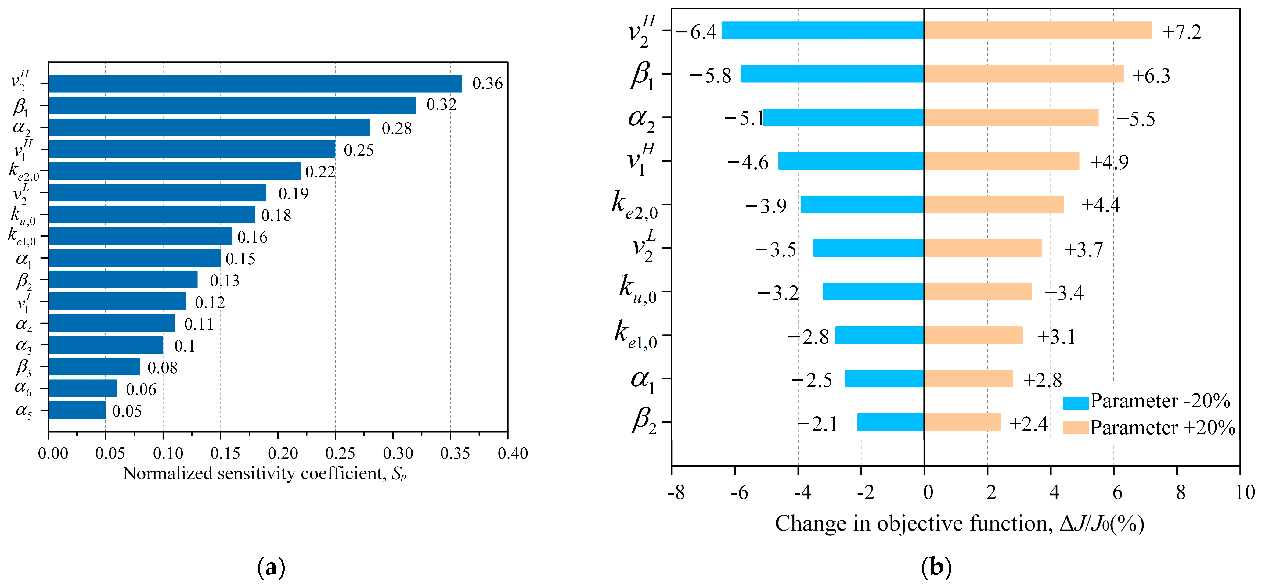
The results of the local sensitivity analysis are presented in Figure 9.
As shown in Figure 9a, the upper threshold of the relative lateral velocity,   v 2 H , exhibits the highest sensitivity, with Sp = 0.36, followed by the high-response output-scaling coefficient β 1 and input-quantization coefficient α 2 , with sensitivity indices of 0.32 and 0.28, respectively. By contrast, the low-response coefficients α 5 , α 6 , β 3 exhibit relatively small sensitivity indices, indicating that moderate variations in the low-response parameter set have a comparatively limited influence on the overall performance index.
The corresponding ± 20% perturbation results are further summarized using the tornado plot in Figure 9b. A ± 20% perturbation of v 2 H results in relative variations of approximately −6.4% and 7.2%, respectively, in the overall objective function, representing the largest response among the investigated parameters. The maximum variations associated with β 1 and α 2 are approximately 6.3% and 5.5%, respectively, whereas the effects of the remaining parameters are comparatively smaller over the same perturbation range.
These results indicate that the performance of the PSTFC does not exhibit excessive local dependence on most individual parameters within the investigated perturbation range, although the upper state thresholds and the corresponding high-response scaling coefficients require comparatively careful calibration. In particular v 2 H , β 1 , and α 2 should receive greater attention when transferring the controller to vehicle configurations with different suspension or carbody characteristics. The sensitivity analysis therefore not only quantifies the dependence of the PSTFC on its tuning parameters but also provides a systematic basis for subsequent recalibration under varying vehicle and operating conditions.

3.3. Design of the Skyhook-Parameter Self-Tuning Fuzzy Controller

In this study, independent dual-input fuzzy controllers are employed to control the lateral dampers of the secondary suspension systems on both the front and rear bogies. The damping forces output by these controllers are used as inputs to the flexible carbody dynamic model of the metro vehicle developed in ADAMS/Rail. A total of four input channels are defined, corresponding to the number of lateral dampers in a single vehicle unit. In the MATLAB/Simulink-based skyhook-PSTFC Model, two variables are selected as inputs: the carbody lateral velocity and the relative lateral velocity between the carbody and bogie frame. The output variable is the lateral damping force applied by the secondary suspension.
One of the essential components of the fuzzy control system is the membership function, which defines how crisp numerical inputs are mapped to fuzzy linguistic variables. Considering the trade-off between control effectiveness and computational efficiency, the output variable (damping force) is divided into seven fuzzy subsets: (PA|PB|PC|PD|PE|PF|PG). Considering the characteristics of different membership function types, Gaussian functions are selected for the two input variables to ensure smooth and stable control performance. For the output variable, triangular membership functions are employed to enable faster response, which is essential for meeting the real-time requirements of vibration suppression.
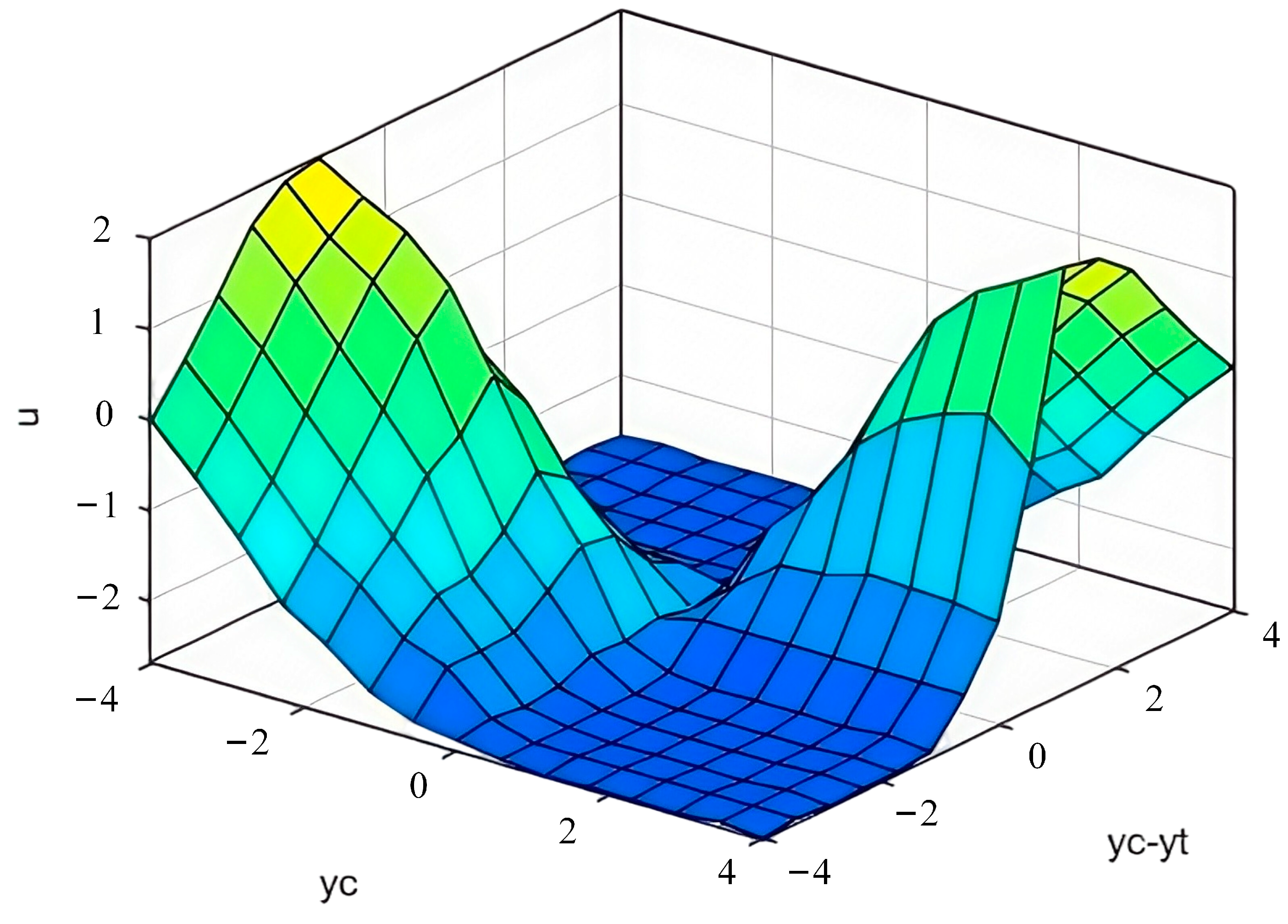
Fuzzy control rules, established through linguistic variables, are a fundamental component of fuzzy logic controllers, enabling the mapping between input and output variables. In this study, the rule base was initially constructed by referencing established fuzzy control schemes used in high-speed trains. To adapt it to metro vehicle applications, the differences in operational velocity, damper characteristics, and track irregularity spectra between metro and high-speed railway systems were carefully analyzed. Accordingly, the fuzzy sets of key input variables (e.g., vehicle speed and relative velocity) were redefined, and the associated linguistic term weights were adjusted to avoid oversensitivity or sluggish response under varying dynamic conditions. Moreover, the control rules were further optimized based on the vibration characteristics of the flexible carbody. Specifically, the relationship between the excitation of flexible structural modes and the control output (i.e., damping force) was analyzed to reverse-engineer the mapping between input combinations and output linguistic terms. A systematic rule selection procedure was performed using a co-simulation platform that integrates MATLAB/Simulink with ADAMS/Rail. Multiple rule set configurations were evaluated using dynamic performance indicators, and the optimal rule base was selected based on control accuracy and robustness. The resulting input–output relationship surface derived from the optimized fuzzy rule base is illustrated in Figure 10.
Based on the aforementioned procedure, a fuzzy controller incorporating the skyhook damping principle was developed. Building upon this foundation, a skyhook parameter self-tuning fuzzy controller was designed by integrating the proposed self-adjustment mechanism. This enables real-time tuning of the fuzzy controller’s quantization and scaling factors. The adaptive mechanism is implemented using an S-Function module, which dynamically adjusts control parameters in response to changes in system state variables. The architecture of the designed skyhook parameter self-tuning fuzzy controller and the internal logic flow of its self-tuning S-Function module are illustrated in Figure 11.
As shown in Figure 11, the subsystem block represents the parameter self-tuning module within the fuzzy controller. The parameter self-adjustment process implemented in the S-Function module is detailed in the embedded flowchart.


4. Semi-Active Suspension Control Simulation and Analysis for Metro Vehicles

Based on the previously developed skyhook-parameter self-tuning fuzzy controller and the established metro vehicle dynamic model, a semi-active vibration control simulation is conducted and analyzed. A co-simulation platform integrating ADAMS/Rail and MATLAB is constructed. Through comparative simulations of different control strategies, the control effectiveness on carbody vibration response and improvements in vehicle dynamic performance are evaluated, thereby validating the effectiveness of the proposed control method.

4.1. Co-Simulation Model for Semi-Active Control

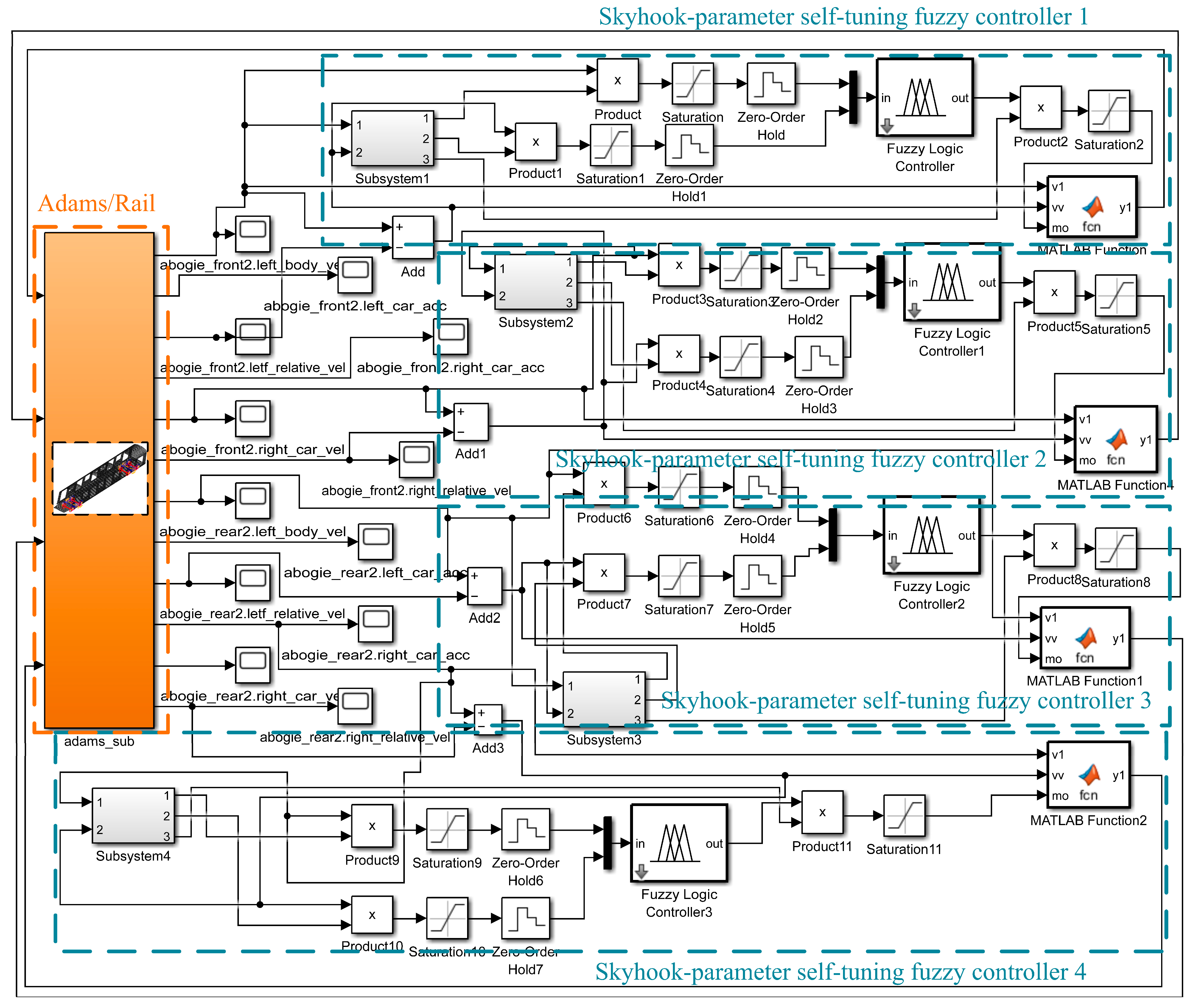
Based on the skyhook fuzzy controller structure shown in Figure 11, a co-simulation model for semi-active control of the metro vehicle was established by integrating the proposed skyhook parameter self-tuning fuzzy control strategy, as illustrated in Figure 12.

4.2. Comparison of Carbody Vibration Acceleration Control Performance

Simulations were carried out on metro vehicle models under four different control strategies:
(1)
Passive suspension;
(2)
Skyhook control;
(3)
Fuzzy skyhook control;
(4)
The skyhook-PSTFC.
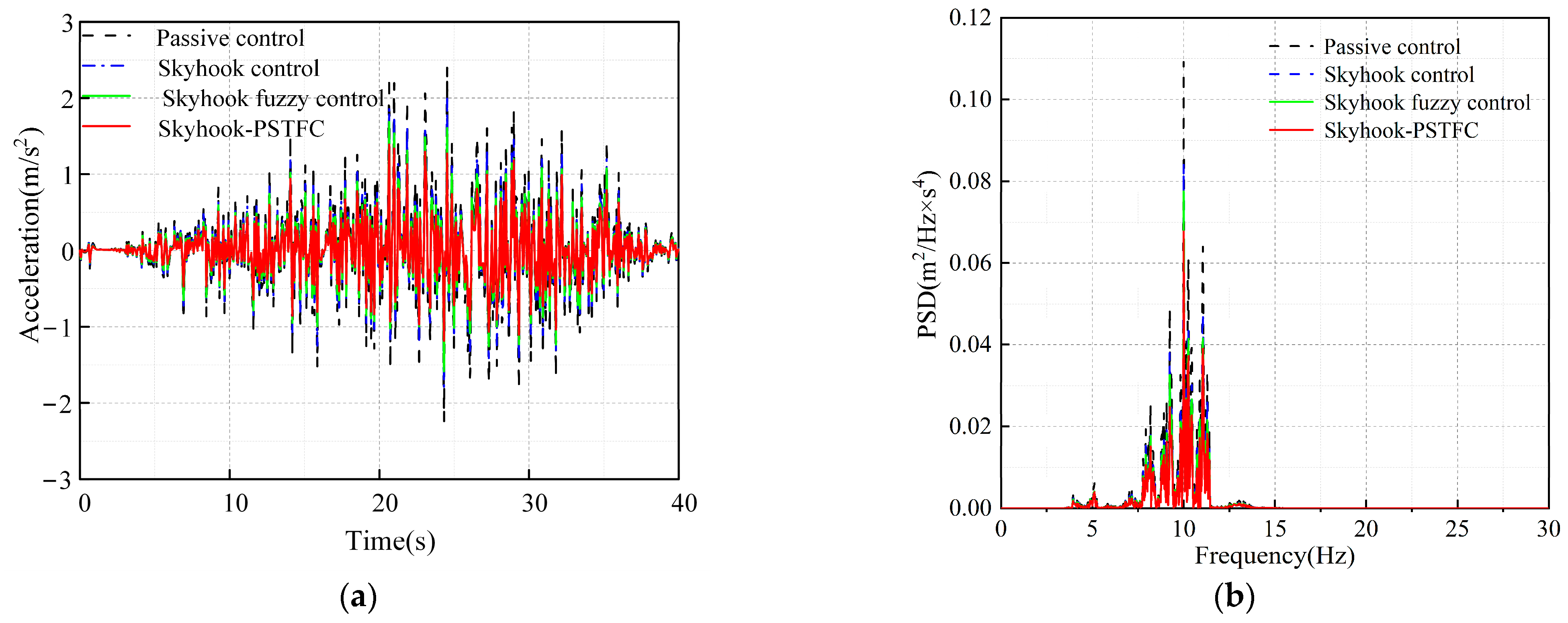
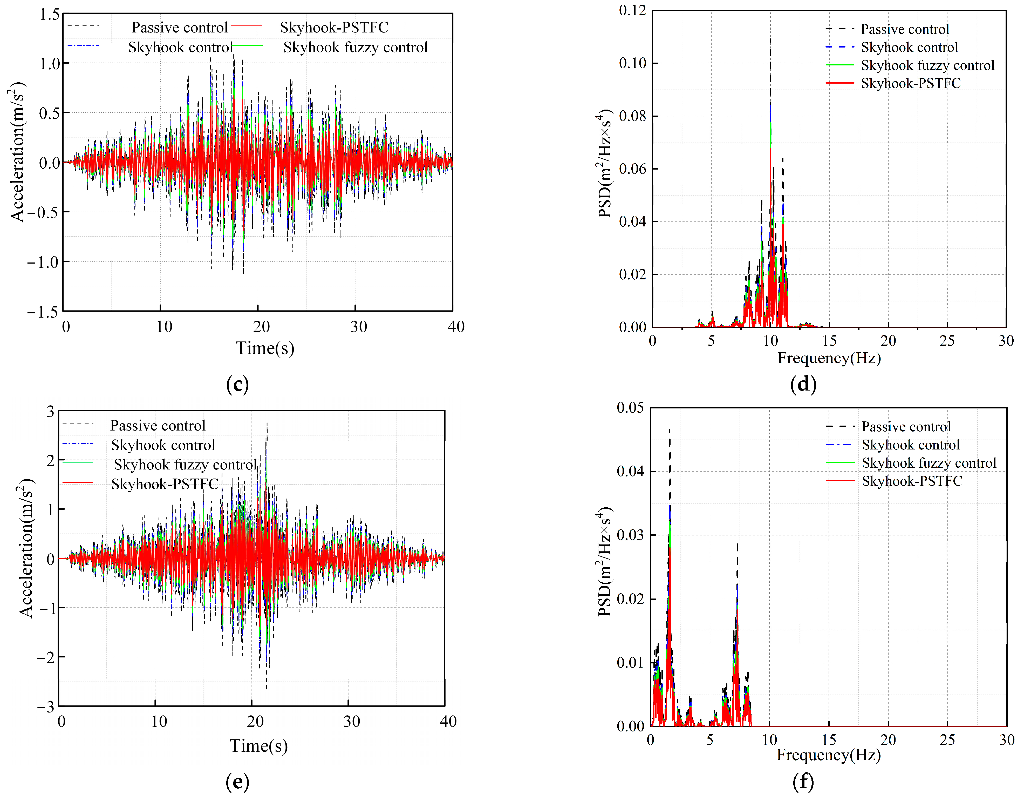
Since the semi-active control is primarily applied to the secondary lateral dampers, the analysis focuses on calculating the lateral vibration acceleration and its PSD at the front, middle, and rear sections of the metro carbody. The resulting acceleration responses and corresponding PSDs under three different semi-active control strategies are presented in Figure 13.
As shown in Figure 13, the lateral vibration responses at the front, middle, and rear sections of the carbody are significantly more attenuated under the skyhook-PSTFC strategy compared to the other two semi-active control methods. Specifically, the fuzzy skyhook control strategy achieves reductions of 30.2%, 28.3%, and 22.9% at the same positions. In contrast, the proposed self-tuning fuzzy control strategy delivers the highest reductions of 40.6%, 36.2%, and 35.7%, respectively. These results clearly demonstrate that the skyhook-PSTFC offers superior vibration attenuation performance, and is more effective in suppressing carbody lateral vibrations than conventional semi-active control approaches.
The lateral acceleration PSD at the front, middle, and rear sections of the metro vehicle carbody exhibits significant variation under different control strategies. At all measurement locations, the skyhook-PSTFC strategy (red curve) demonstrates the lowest PSD amplitudes within the frequency bands where vibration energy is most concentrated.
At the front section (Figure 13b), a prominent resonance peak appears around 7.1 Hz. Both conventional skyhook control and skyhook fuzzy control offer limited attenuation in this frequency range. In contrast, the skyhook-PSTFC strategy exhibits the lowest PSD level within the primary frequency band (5–9 Hz), with a 41.7% reduction in peak PSD amplitude compared to passive control at the resonance frequency.
At the middle section (Figure 13d), the dominant resonance peak occurs at approximately 10.1 Hz, corresponding to the modal frequency of the tripartite out-of-phase roof bending mode. Among the tested strategies, skyhook-PSTFC demonstrates superior energy suppression in this range. Compared to passive control, it achieves a 38.2% reduction in PSD amplitude at the peak frequency, effectively mitigating the structural vibration energy induced by flexible body modes.
At the rear section (Figure 13f), passive control results in two distinct energy peaks at approximately 2.2 Hz and 8 Hz. The low-frequency peak indicates a rigid-body resonance, while the higher-frequency peak corresponds to the rear-end rhomboidal mode. The skyhook-PSTFC strategy substantially reduces the PSD amplitudes at both frequencies, demonstrating excellent broadband vibration attenuation performance.
In summary, the proposed skyhook-PSTFC method offers significantly enhanced resonance energy suppression compared to other control strategies. It not only enables effective broadband reduction in vibrational energy but also efficiently suppresses local resonances caused by flexible structural modes, highlighting its robustness and applicability in metro vehicle suspension systems.

4.3. Comparison of Improvements in Vehicle Dynamic Performance

According to the Chinese standard GB5599-2019, the lateral acceleration data measured at the rear section of the carbody is utilized to calculate the vehicle dynamic performance indices. The evaluation metrics include the Root Mean Square (RMS) value and the Sperling ride comfort index. The improvements in dynamic performance under different semi-active control strategies are summarized in Table 4.
As shown in Table 4, all three semi-active control strategies—skyhook control, skyhook fuzzy control, and the proposed skyhook-PSTFC—contribute to improvements in the lateral ride comfort performance of the metro vehicle.
With the application of skyhook fuzzy control, the RMS value further decreased to 0.1077 (19.7% reduction), and the Sperling index was reduced to 1.3492 (12.9% improvement).
The proposed skyhook-PSTFC strategy achieved the most significant enhancement: the RMS value was reduced to 0.1015, corresponding to a 24.3% reduction, and the Sperling index dropped to 1.2864, showing a 16.9% improvement over passive control.
These results clearly demonstrate that the skyhook-PSTFC strategy offers superior effectiveness in improving the lateral ride comfort performance of metro vehicles under dynamic operating conditions.

4.4. Statistical Repeatability Under Stochastic Track Excitation

The preceding analysis was based on a representative track-irregularity realization and demonstrated that the proposed PSTFC can effectively suppress the lateral vibration of the flexible carbody. Track irregularity is inherently stochastic, however, and the control performance obtained from a single excitation realization may be influenced by its specific random characteristics. To assess the statistical repeatability of the reported improvements, 30 independent track-irregularity realizations were generated using different random-phase sequences while retaining the same prescribed target spectrum, vehicle operating parameters, suspension parameters, and controller settings. The generated realizations were verified to preserve the statistical characteristics of the target irregularity spectrum. For each realization, the passive suspension, skyhook control, fuzzy skyhook control, and PSTFC were subjected to exactly the same track input, thereby enabling paired comparisons and minimizing the influence of sample-to-sample variations in stochastic excitation.
For each track-irregularity realization, the root-mean-square (RMS) lateral acceleration at the front, middle, and rear sections of the carbody was calculated as
a RMS , j ( n ) 1 T e t 0 t 0 + T e a j ( n ) ( t ) 2 d t
where j ∈ {f, m, r} denotes the front, middle, and rear carbody locations, respectively; t0 is the starting time of the evaluation interval; Te is the effective evaluation duration; and n = 1, 2, …, N, with N = 30 in the present analysis. The same evaluation interval was used for all control strategies to avoid statistical bias associated with initial transients or differences in data duration.
For location j and control strategy (c), the ensemble-averaged RMS acceleration was calculated as
a ¯ j , c = 1 N n = 1 N a RMS , j , c ( n )
The corresponding mean reduction relative to the passive suspension was defined as
η ¯ j , c = a ¯ j , passive a ¯ j , c a ¯ j , passive × 100 %
To quantify the dispersion of the control performance across stochastic track realizations, the sample standard deviation, coefficient of variation (CV), and 95% confidence interval were additionally evaluated. The CV was calculated as
C V j , c = s j , c a ¯ j , c × 100 %
The statistical results obtained from the 30 independent track-irregularity realizations are summarized in Table 5.
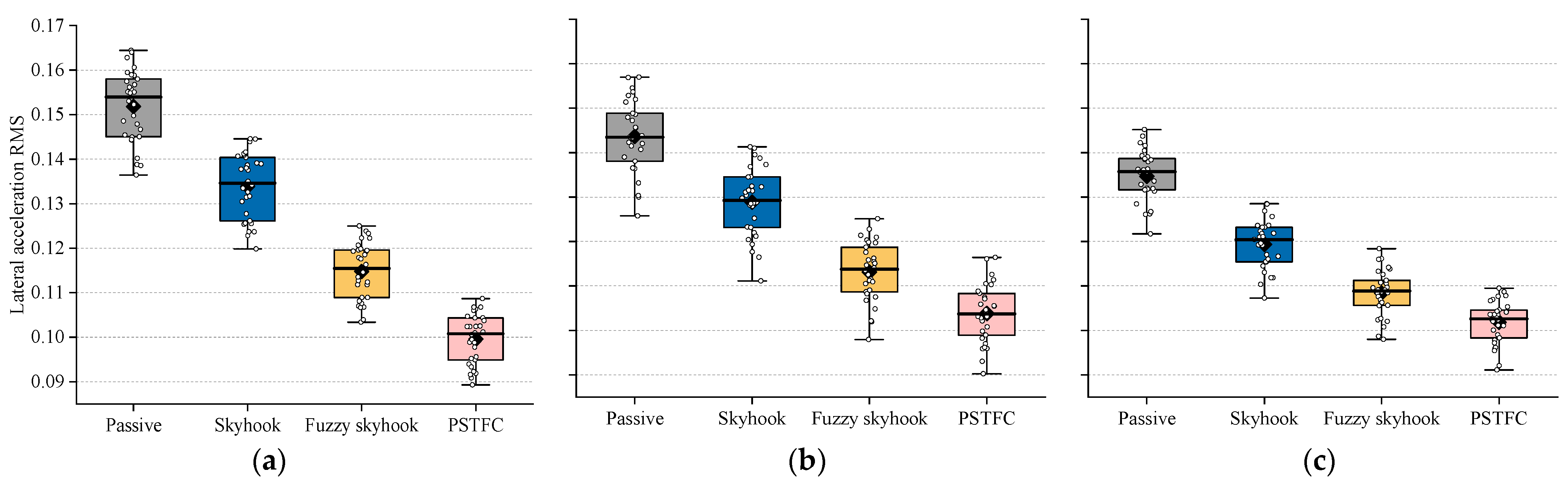
As summarized in Table 5, the PSTFC consistently achieves the lowest mean lateral acceleration RMS at all three carbody locations over the 30 independent track-irregularity realizations. Compared with the passive suspension, the mean RMS values at the front, middle, and rear of the carbody are reduced by 34.4%, 27.7%, and 24.4%, respectively. Moreover, the coefficients of variation of the PSTFC responses remain within 4.66–6.26%, comparable to those obtained with the other control strategies. This indicates that the improved vibration-suppression performance is not accompanied by increased response variability under stochastic track excitation. Nevertheless, ensemble-averaged quantities alone cannot fully characterize the distribution and repeatability of the control performance. Therefore, the distributions of the lateral acceleration RMS obtained from the 30 realizations are further presented as box plots in Figure 14.
As shown in Figure 14, variations among the stochastic track-irregularity realizations introduce a discernible dispersion in the lateral vibration responses of the carbody. Nevertheless, the overall performance ranking among the four suspension strategies remains consistent. All three semi-active control strategies shift the RMS distributions toward lower values relative to the passive suspension, with the PSTFC exhibiting the lowest overall RMS levels at the front, middle, and rear locations.
It is also noteworthy that the CV values for all four suspension strategies remain within a comparable range of 4.27–6.26%. Although the PSTFC adjusts its control scaling parameters online in response to the instantaneous vibration state, the resulting dispersion is not appreciably larger than that observed for conventional skyhook and fuzzy skyhook control. This observation indicates that the improvement in the mean vibration attenuation is not accompanied by an abnormal increase in sensitivity to stochastic track excitation.
Because all control strategies were evaluated using identical excitation inputs for each realization, paired statistical comparisons were further performed between the PSTFC and the conventional fuzzy skyhook controller. The normality of the within-realization differences was first examined using the Shapiro–Wilk test. A paired-sample (t)-test was employed when the normality assumption was satisfied; otherwise, the Wilcoxon signed-rank test was used. The differences in lateral acceleration RMS between the PSTFC and conventional fuzzy skyhook control are statistically significant at all three carbody locations (p < 0.001). These results indicate that the improvement achieved by the PSTFC is not attributable to a particular track-irregularity realization but is consistently maintained across independent stochastic excitations.
Overall, although stochastic variations in track irregularity alter the absolute vibration level of the vehicle, they do not change the overall performance relationship among the investigated control strategies. The results from the 30 independent realizations therefore provide statistical evidence that the vibration-reduction capability observed under the representative excitation condition is repeatable across different spatial locations of the flexible carbody. The robustness of the PSTFC against variations in vehicle speed, passenger load, track conditions, and suspension-parameter uncertainties is further investigated in the following section.

4.5. Robustness Under Varying Operating Conditions and Suspension-Parameter Uncertainties

Section 4.4 demonstrated the statistical repeatability of the PSTFC across independent stochastic track-irregularity realizations. In practical metro operation, however, vehicle dynamics are additionally influenced by variations in operating speed, passenger load, track condition, and suspension characteristics. Satisfactory performance under a single nominal vehicle configuration is therefore insufficient to establish the robustness of the proposed strategy. Accordingly, this section further evaluates the PSTFC under off-nominal operating conditions and suspension-parameter uncertainties.
A nominal condition, denoted by S0, was first defined with a vehicle speed of 60 km/h, nominal passenger load, the baseline track-irregularity condition, and nominal secondary lateral stiffness k2y,0 and damping parameter c2y,0. A one-factor-at-a-time strategy was then adopted to independently investigate variations in vehicle speed, passenger load, track-irregularity intensity, and secondary-suspension parameters while maintaining all other quantities at their nominal values. In addition, a combined off-nominal condition was considered to examine whether simultaneous deviations in several factors lead to substantial deterioration in control performance.
Importantly, the velocity thresholds and tuning coefficients calibrated in Section 3.2 were retained unchanged throughout all robustness simulations. No scenario-dependent recalibration or re-optimization of the PSTFC was performed. Furthermore, identical track inputs and initial conditions were applied to all control strategies within each scenario. Consequently, variations in the resulting performance reflect the intrinsic adaptability of the controllers rather than improvements obtained through scenario-specific retuning. The considered operating conditions and corresponding system parameter settings are presented in Table 6.
For the track-irregularity variation, the spatial profile was scaled according to
r λ ( s ) = λ q r 0 ( s )
where r0(s) denotes the baseline spatial track-irregularity profile. Accordingly, when the spatial irregularity amplitude is directly scaled, the corresponding power spectral density satisfies
S λ ( Ω ) = λ q 2 S 0 ( Ω )
Thus, λq represents an amplitude-scaling factor rather than a direct scaling factor of the PSD.
For operating condition q, the RMS reduction achieved by control strategy c relative to the passive suspension was defined as
η j , q c = a RMS , j , q passive a RMS , j , q c a RMS , j , q passive × 100 %
where j = f,m,r denotes the front, middle, and rear carbody locations, respectively.
The additional improvement provided by the PSTFC relative to conventional fuzzy skyhook control was quantified as
G j , q = a RMS , j , q Fuzzy a RMS , j , q PSTFC a RMS , j , q Fuzzy × 100 %
A performance-retention ratio was further introduced to quantify the extent to which the nominal control capability is preserved under off-nominal conditions:
ρ j = min q Ω η j , q PSTFC η j , 0 PSTFC × 100 %
The value of ρj closer to 100% indicates less degradation in the vibration-reduction capability over the investigated operating-condition space.
The simulation results for the control performance under different operating conditions and system parameter uncertainties are summarized in Table 7.
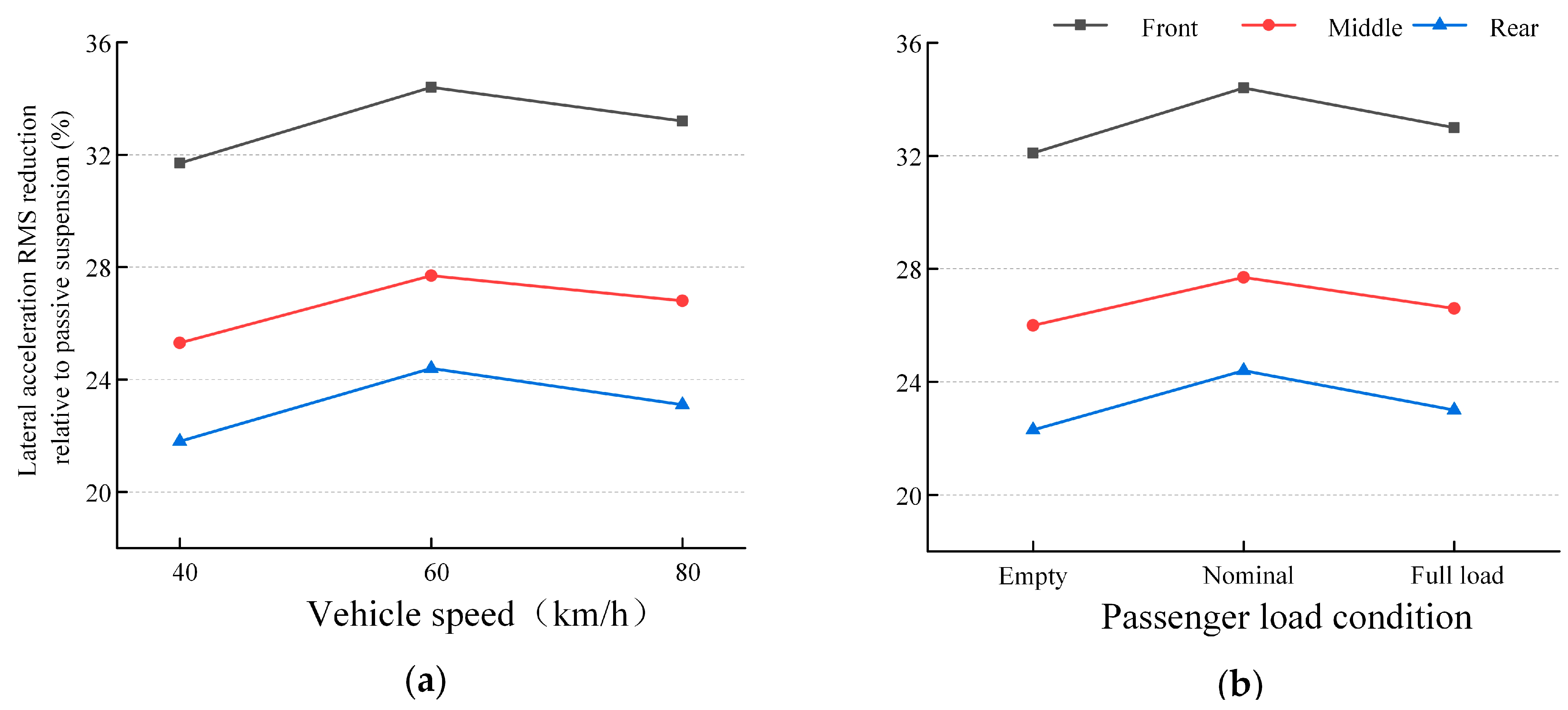
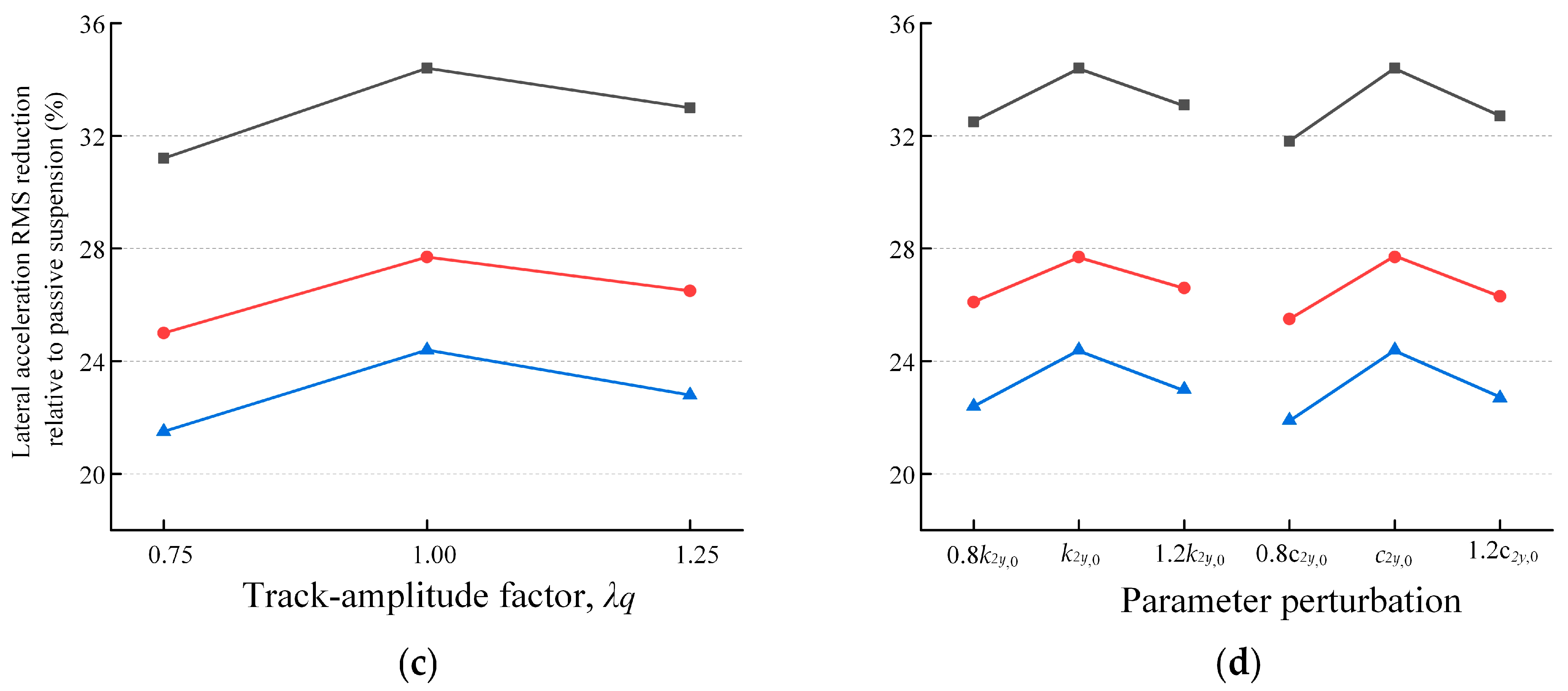
As summarized in Table 7, the PSTFC consistently outperforms the conventional fuzzy skyhook controller over the entire range of operating conditions and suspension-parameter variations considered. Under the single-factor scenarios (S1–S10), the reduction in lateral acceleration RMS achieved by the PSTFC remains above 31.2%, 25.0%, and 21.5% at the front, middle, and rear of the carbody, respectively. Relative to the nominal condition, these values correspond to performance-retention ratios of 90.7%, 90.3%, and 88.1%, indicating that the control effectiveness is only moderately affected by variations in vehicle speed, passenger load, track-excitation intensity, and secondary-suspension parameters. Even under the combined off-nominal condition S11, the PSTFC retains RMS reductions of 29.4%, 23.7%, and 19.8%, respectively, while maintaining a 12.6% improvement in the Sperling index. These results demonstrate that the proposed controller does not rely on a narrowly tuned nominal operating point and retains appreciable vibration-suppression capability when multiple operating and model parameters deviate simultaneously. To further elucidate the influence of individual factors, the single-factor results are visualized in Figure 15.
As shown in Figure 15a, variations in vehicle speed produce only moderate changes in the vibration-suppression performance of the PSTFC. When the operating speed varies from 40 to 80 km/h, the reductions in lateral acceleration RMS remain within 31.7–34.4%, 25.3–27.7%, and 21.8–24.4% at the front, middle, and rear of the carbody, respectively. Although the highest reductions are obtained under the nominal condition of 60 km/h, no pronounced deterioration is observed at either lower or higher speeds. A similar trend can be observed for variations in passenger load, as shown in Figure 15b. The RMS reductions remain above 32.1%, 26.0%, and 22.3% for the three measurement locations from the empty-load to the full-load condition. These results indicate that changes in vehicle speed and passenger load have a relatively limited influence on the control effectiveness of the PSTFC within the investigated operating range.
Figure 15c further illustrates the influence of track-irregularity excitation intensity. For the three excitation levels considered, the PSTFC achieves RMS reductions of 31.2–34.4%, 25.0–27.7%, and 21.5–24.4% at the front, middle, and rear of the carbody, respectively. The slightly lower percentage reduction obtained at the lower excitation level (λq = 0.75) should be interpreted with caution because the reduction ratio is normalized by the passive response under the corresponding excitation condition; therefore, a smaller percentage reduction does not necessarily imply a larger absolute vibration response. More importantly, the PSTFC maintains a substantial control benefit over the entire range of track-excitation intensities considered, demonstrating that its effectiveness is not confined to the nominal excitation level.
The effects of secondary-suspension parameter uncertainties are presented in Figure 15d. When the secondary lateral stiffness k2y is varied by ±20% from its nominal value, the RMS reductions remain within 32.5–34.4%, 26.1–27.7%, and 22.4–24.4% at the three carbody locations. Correspondingly, a ±20% variation in the equivalent secondary lateral damping c2y results in reductions of 31.8–34.4%, 25.5–27.7%, and 21.9–24.4%, respectively. Within the investigated uncertainty range, variations in damping produce a slightly greater change in control performance than variations in stiffness, particularly when the damping is reduced. Nevertheless, neither parameter perturbation leads to an abrupt degradation of the control effectiveness, indicating that the PSTFC exhibits a relatively low sensitivity to moderate uncertainties in the secondary-suspension parameters.
Considering all single-factor off-nominal scenarios (S1S10), the minimum lateral acceleration RMS reductions achieved by the PSTFC are 31.2%, 25.0%, and 21.5% at the front, middle, and rear of the carbody, respectively. Relative to the corresponding nominal improvements of 34.4%, 27.7%, and 24.4%, the resulting performance-retention ratios are 90.7%, 90.3%, and 88.1%, respectively. The slightly lower retention at the rear of the carbody indicates that the control benefit at this location is comparatively more sensitive to variations in the investigated conditions, although a substantial vibration reduction is still maintained.
The combined off-nominal scenario S11 imposes simultaneous variations in vehicle speed, passenger load, track-excitation intensity, secondary lateral stiffness, and damping, thereby providing a more demanding assessment than the individual perturbations shown in Figure 15. As reported in Table 7, the PSTFC still achieves RMS reductions of 29.4%, 23.7%, and 19.8% at the front, middle, and rear of the carbody, corresponding to 85.5%, 85.6%, and 81.1% of the nominal control effectiveness, respectively. These values remain higher than those of the conventional fuzzy skyhook controller (18.7%, 15.6%, and 13.5%) by 10.7, 8.1, and 6.3 percentage points, respectively. Meanwhile, the improvement in the Sperling index remains 12.6% under this combined off-nominal condition.
Overall, the results demonstrate that the PSTFC maintains effective lateral vibration suppression over the investigated variations in vehicle speed, passenger load, track-excitation intensity, and secondary-suspension parameters. Importantly, the same controller parameters are retained throughout all scenarios without condition-specific retuning. The persistent performance advantage of the PSTFC under both individual parameter variations and the combined off-nominal condition indicates that the proposed control strategy is not restricted to a narrowly defined nominal operating point and retains satisfactory control effectiveness within the investigated range of operating conditions and suspension-parameter uncertainties.

4.6. Computational Efficiency and Real-Time Implementation Feasibility

In addition to vibration-suppression performance, computational efficiency is an important consideration for the practical implementation of a semi-active suspension controller. In the proposed PSTFC, the membership functions and fuzzy rule base remain fixed during operation. The online self-tuning mechanism only updates the two input quantization factors, ke1 and ke2, and the output scaling factor, ku, according to the instantaneous carbody lateral velocity v1 and the carbody–bogie relative lateral velocity v2. Consequently, each control update requires only several threshold comparisons, coefficient selections, and scalar multiplications in addition to the conventional fuzzy inference procedure. No iterative optimization, online system identification, matrix inversion, or rule-base reconstruction is involved. The additional computational complexity introduced by the self-tuning layer is therefore O(1), and the overall computational order of the PSTFC remains essentially unchanged from that of the conventional fuzzy skyhook controller.
Considering the dominant frequency range identified from the modal and vibration-response analyses, a controller sampling period of Ts = 5 ms, corresponding to a sampling frequency of fs = 200 Hz, was adopted for the reference implementation. In particular, the highest carbody flexible mode of primary concern in the present study is approximately 11.1 Hz, such that the selected sampling frequency provides approximately 18 control updates per vibration cycle at this frequency. The control command calculated at each sampling instant is held constant until the subsequent update. To further ensure that the numerical results are not dependent on an excessively high controller update rate, the influence of the sampling period is examined subsequently.
To quantify the online computational burden, the execution time of the complete control algorithm was evaluated independently of the ADAMS/Rail solver and co-simulation communication overhead. The benchmark includes signal normalization, fuzzy inference, parameter self-tuning, and the calculation of the damping-force commands for all controlled secondary lateral dampers. After an initial warm-up stage, N = 105 consecutive controller updates were performed. The mean execution time, 99th-percentile execution time, and observed maximum execution time were recorded. The corresponding quantities are defined as
t ¯ c = 1 N i = 1 N t c , i
t c , max = max 1 i N t c , i
and the maximum computational utilization relative to the prescribed sampling period is evaluated as
U max = t c , max T s × 100 %
The corresponding real-time computational margin can be expressed as
M RT = T s t c , max
The timing benchmark was performed on a computer equipped with an Intel Core i7-14700H processor and 32 GB RAM using MATLAB/Simulink R2023b. The representative results are summarized in Table 8.
As shown in Table 8, the conventional fuzzy skyhook controller requires an average execution time of 0.245 ms, whereas that of the PSTFC increases only slightly to 0.269 ms. Thus, the proposed self-tuning mechanism introduces an additional average computational cost of approximately 0.024 ms, corresponding to an increase of 9.8% relative to the conventional fuzzy controller. More importantly, the observed maximum execution time of the PSTFC is only 0.418 ms, accounting for 8.36% of the 5-ms sampling interval. This corresponds to a computational margin of approximately MRT = 12.0, indicating that the additional online parameter scheduling constitutes only a small fraction of the available computation interval. The increase in computational cost is therefore modest relative to the improvement in vibration-control performance obtained with the PSTFC.
To examine the dependence of the control performance on the sampling frequency, additional simulations were performed using Ts = 1, 2, 5, and 10 ms under the same nominal operating condition. The vehicle model, track-irregularity input, controller parameters, and initial conditions were kept unchanged, and only the controller update interval was varied. The resulting lateral acceleration RMS values and Sperling indices are given in Table 9.
As shown in Table 9, the control performance is only weakly affected when the sampling period is varied within the investigated range. Compared with Ts =1 ms, increasing the sampling period to 5 ms changes the lateral acceleration RMS at the front, middle, and rear of the carbody by approximately 0.40%, 0.39%, and 0.40%, respectively, while the Sperling index changes by approximately 0.30%. Even when the sampling period is increased to 10 ms, the increase in the corresponding performance indices remains approximately 1%. These results indicate that the vibration attenuation achieved by the PSTFC is not dependent on an unrealistically high controller update frequency. Accordingly, Ts = 5 ms provides an appropriate compromise between temporal resolution and computational demand for the present numerical implementation.
From an onboard implementation perspective, the PSTFC is also advantageous because the self-tuning procedure consists of deterministic algebraic operations and a fixed fuzzy inference structure, making it amenable to implementation on a conventional embedded control platform. Nevertheless, the computational timing reported above represents the algorithmic execution time in the numerical environment and should not be interpreted as a hardware-in-the-loop or embedded-hardware validation. In an actual vehicle, sensor acquisition and signal estimation, communication latency, actuator dynamics, force/current conversion, and hardware-specific execution characteristics would contribute additional delays. These effects are not explicitly included in the present co-simulation framework and will require further assessment using an embedded controller and hardware-in-the-loop or experimental platform.
Overall, the results indicate that the proposed self-tuning mechanism introduces only a modest computational overhead relative to conventional fuzzy skyhook control, while retaining a substantial computational margin at the selected 200-Hz update frequency. Together with the limited sensitivity of the control performance to the sampling period, these results provide preliminary evidence for the real-time computational feasibility of the PSTFC. However, the present analysis establishes computational feasibility rather than experimental real-time validation, and the influence of sensing, communication, and actuator delays should be further investigated before practical onboard deployment.

5. Conclusions

This study proposed a parameter self-tuning fuzzy skyhook control (PSTFC) strategy for the semi-active lateral suspension of metro vehicles with flexible carbodies. Unlike conventional fuzzy skyhook controllers with fixed quantization and scaling factors, the proposed method retains the predefined membership functions and fuzzy rule base while adjusting the input quantization factors and output scaling factor online according to the instantaneous carbody lateral velocity and carbody–bogie relative lateral velocity. This state-dependent parameter-scheduling mechanism improves the adaptability of the controller to variations in vibration state without introducing online optimization, parameter identification, or rule-base reconstruction, thereby preserving a relatively simple control structure.
A rigid–flexible coupled vehicle model was established using the Craig–Bampton component-mode synthesis method to account for the influence of carbody structural flexibility. Comparison with field-measured lateral acceleration responses demonstrates that the flexible-carbody model reproduces the measured time- and frequency-domain characteristics more accurately than the corresponding rigid-carbody model, particularly in the frequency bands associated with local flexible modes. The results confirm that carbody flexibility cannot be neglected when evaluating the lateral vibration characteristics and semi-active suspension performance of the investigated metro vehicle.
Under the nominal operating condition, the PSTFC provides greater attenuation of the carbody lateral vibration than the passive suspension, conventional skyhook control, and fuzzy skyhook control. Pronounced reductions in vibration energy are obtained in the dominant frequency bands associated with carbody flexible modes, while the lateral acceleration RMS and Sperling ride index are reduced by 24.3% and 16.9%, respectively, at the representative rear-carbody measurement location. The parameter sensitivity analyses further show that the control performance remains relatively stable over the prescribed ranges of the self-tuning parameters, indicating that the effectiveness of the PSTFC is not restricted to a narrowly selected parameter combination.
The additional statistical and robustness analyses provide further evidence of the consistency of the proposed controller. Across repeated simulations with independent stochastic track-irregularity realizations, the PSTFC maintains lower lateral acceleration levels at the front, middle, and rear of the carbody, without a pronounced increase in response dispersion. Moreover, when vehicle speed, passenger load, track-excitation intensity, and secondary-suspension parameters are varied, the controller retains its vibration-suppression capability without condition-specific retuning. Under the individual off-nominal conditions considered, the minimum reductions in lateral acceleration RMS remain 31.2%, 25.0%, and 21.5% at the front, middle, and rear of the carbody, respectively. Even under the combined off-nominal condition, corresponding reductions of 29.4%, 23.7%, and 19.8% are maintained, confirming that the performance advantage of the PSTFC is not confined to the nominal operating point.
The computational analysis also indicates that the self-tuning mechanism introduces only a modest additional computational burden relative to the conventional fuzzy skyhook controller. With a controller sampling period of 5 ms (200 Hz), the measured execution time remains well below the available sampling interval, while the control performance exhibits only limited variation over the investigated sampling periods. These results provide preliminary evidence for the real-time computational feasibility of the PSTFC. Nevertheless, the present experimental measurements were used to validate the rigid–flexible coupled vehicle model, whereas the closed-loop controller itself has so far been evaluated through ADAMS/Rail–MATLAB co-simulation. Therefore, the present results should be interpreted as evidence of numerical effectiveness, robustness, and computational feasibility rather than as direct validation of onboard implementation. Future work will focus on hardware-in-the-loop and experimental validation incorporating sensor and communication delays, actuator dynamics and constraints, and embedded-controller execution, followed by further evaluation under realistic operating conditions.

Author Contributions

Conceptualization, H.S.; Methodology, H.S.; Software, H.S.; Validation, W.H.; Investigation, W.M.; Resources, W.M.; Data curation, J.S., Y.Y. and W.M.; Writing—original draft, H.S. and W.H.; Writing—review & editing, W.M. and Y.Y.; Visualization, J.S.; Supervision, J.S. and Y.Y.; Project administration, Y.Y.; Funding acquisition, H.S. and W.H. All authors have read and agreed to the published version of the manuscript.

Funding

This work was supported by the National Natural Science Foundation of China (Grant No. 52179086; 5226090174), the Central Guidance for Local Development Projects (Grant No. 23ZYQA0320), Industrial Support Plan Project of Gansu Provincial Education Department (2025CYZC-034), Nanjing Railway Vocational Technology College’s Research Platform Project (Grant No. KYPT2025001), Nanjing Railway Vocational Technology College’s Excellent Innovation and Scientific Research Team Project (Grant No. CXTD2025002). Open Fund Project of Jiangsu Province Rail Transit Intelligent Monitoring and Detection Engineering Center (Grant No. KFJJZN2507; KFJJZN2512), Nanjing Railway Vocational Technology College’s Blue-Collar and Senior Teacher Project (Grant No. RCQL202632).

Data Availability Statement

The raw data supporting the conclusions of this article will be made available by the authors on reasonable request.

Conflicts of Interest

Author Yi You was employed by the company Institute of Industrial Technology, CMCU Engineering Co., Ltd., Chongqing, China. The remaining authors declare that the research was conducted in the absence of any commercial or financial relationships that could be construed as a potential conflict of interest.

Abbreviations

The following abbreviations are used in this manuscript:
PSTFCParameter Self-Tuning Fuzzy Control
PSDPower Spectral Density
RMSRoot Mean Square

References

  1. Shi, J.; Gao, Y.; Long, X.; Wang, Y. Optimizing rail profiles to improve metro vehicle-rail dynamic performance considering worn wheel profiles and curved tracks. Struct. Multidiscip. Optim. 2021, 63, 419–438. [Google Scholar] [CrossRef] [Scilit]
  2. Wang, H.; Gu, A.; Fan, Q.; Xing, X.; Liu, J. Research on Vibration Characteristics of a Flexible Vehicle-Ladder Track System. Urban Rail Transit 2024, 10, 13–27. [Google Scholar] [CrossRef] [Scilit]
  3. Chen, Z.; Zhu, G. Dynamic evaluation on ride comfort of metro vehicle considering structural flexibility. Arch. Civ. Mech. Eng. 2021, 21, 162. [Google Scholar] [CrossRef] [Scilit]
  4. Chen, Z.W.; Zhu, G. Semi-active control of metro vehicle based on flexible multi-body dynamics. J. Traffic Transp. Eng. 2021, 21, 298–309. [Google Scholar]
  5. Kumar, S.; Medhavi, A.; Kumar, R. Active and passive suspension system performance under random road profile excitations. Int. J. Acoust. Vib. 2020, 25, 532–541. [Google Scholar] [CrossRef] [Scilit]
  6. Fu, B.; Giossi, R.L.; Persson, R.; Stichel, S.; Bruni, S.; Goodall, R. Active suspension in railway vehicles: A literature survey. Railw. Eng. Sci. 2020, 28, 3–35. [Google Scholar] [CrossRef] [Scilit]
  7. Jin, T.; Liu, Z.; Sun, S.; Ren, Z.; Deng, L.; Yang, B.; Christie, M.D.; Li, W. Development and evaluation of a versatile semi-active suspension system for high-speed railway vehicles. Mech. Syst. Signal Process 2020, 135, 106338. [Google Scholar] [CrossRef] [Scilit]
  8. Zhang, H.; Wang, E.; Min, F.; Subash, R.; Su, C. Skyhook-based semi-active control of full-vehicle suspension with magneto-rheological dampers. Chin. J. Mech. Eng. 2013, 26, 498–505. [Google Scholar] [CrossRef] [Scilit]
  9. Liu, C.; Chen, L.; Yang, X.; Zhang, X.; Yang, Y. General theory of skyhook control and its application to semi-active suspension control strategy design. IEEE Access 2019, 7, 101552–101560. [Google Scholar] [CrossRef] [Scilit]
  10. Huang, D.S.; Zhang, J.Q.; Liu, Y.L. The PID semi-active vibration control on nonlinear suspension system with time delay. Int. J. Intell. Transp. 2018, 16, 125–137. [Google Scholar] [CrossRef] [Scilit]
  11. Wang, X. Semi-active adaptive optimal control of vehicle suspension with a magnetorheological damper based on policy iteration. J. Intel. Mat. Syst. Str. 2018, 29, 255–264. [Google Scholar] [CrossRef] [Scilit]
  12. Nguyen, S.D.; Lam, B.D.; Ngo, V.H. Fractional-order sliding-mode controller for semi-active vehicle MRD suspensions. Nonlinear Dyn. 2020, 101, 795–821. [Google Scholar] [CrossRef] [Scilit]
  13. Tang, X.; Du, H.; Sun, S.; Ning, D.; Xing, Z.; Li, W. Takagi–Sugeno fuzzy control for semi-active vehicle suspension with a magnetorheological damper and experimental validation. IEEE ASME Trans. Mechatron. 2016, 22, 291–300. [Google Scholar] [CrossRef] [Scilit]
  14. Soliman, A.M.A.; Kaldas, M.M.S. Semi-active suspension systems from research to mass-market–A review. J. Low Freq. Noise Vib. Act. Control 2021, 40, 1005–1023. [Google Scholar] [CrossRef] [Scilit]
  15. Zhang, B.; Zhao, H.; Zhang, X. Adaptive variable domain fuzzy PID control strategy based on road excitation for semi-active suspension using CDC shock absorber. J. Vib. Control 2024, 30, 860–875. [Google Scholar] [CrossRef] [Scilit]
  16. Li, G.; Ruan, Z.; Gu, R.; Hu, G. Fuzzy sliding mode control of vehicle magnetorheological semi-active air suspension. Appl. Sci. 2021, 11, 10925. [Google Scholar] [CrossRef] [Scilit]
  17. Abut, T.; Salkim, E. Control of quarter-car active suspension system based on optimized fuzzy linear quadratic regulator control method. Appl. Sci. 2023, 13, 8802. [Google Scholar] [CrossRef] [Scilit]
  18. Tseng, H.E.; Hrovat, D. State of the art survey: Active and semi-active suspension control. Veh. Syst. Dyn. 2015, 53, 1034–1062. [Google Scholar] [CrossRef] [Scilit]
  19. Ma, T.; Bi, F.; Wang, X.; Tian, C.; Lin, J.; Wang, J.; Pang, G. Optimized fuzzy skyhook control for semi-active vehicle suspension with new inverse model of magnetorheological fluid damper. Energies 2021, 14, 1674. [Google Scholar] [CrossRef] [Scilit]
  20. Zhang, D.; Tao, Z.-Y.; Zhou, K.; Zhou, F.-R.; Peng, Q.-Y.; Tang, Y.-Y. Improving the energy efficiency and riding comfort of high-speed trains across slopes by the optimized suspension control. Energy 2024, 307, 132660. [Google Scholar] [CrossRef] [Scilit]
  21. Meng, J.; Song, H.; Xu, R.; Li, D.; Chen, X. Skyhook Fuzzy Control of Semi-active Suspension of Flexible Carbody of Metro Vehicle. Noise Vib. Control 2022, 42, 13–19. [Google Scholar]
  22. Milecki, A.; Hauke, M. Application of magnetorheological fluid in industrial shock absorbers. Mech. Syst. Signal Process. 2012, 28, 528–541. [Google Scholar] [CrossRef] [Scilit]
  23. Kurczyk, S.; Pawełczyk, M. Fuzzy control for semi-active vehicle suspension. J. Low Freq. Noise Vib. Act. Control 2013, 32, 217–225. [Google Scholar] [CrossRef] [Scilit]
  24. Chen, G.; Jiang, Y.; Tang, Y.; Xu, X. Revised adaptive active disturbance rejection sliding mode control strategy for vertical stability of active hydro-pneumatic suspension. ISA Trans. 2023, 132, 490–507. [Google Scholar] [CrossRef] [Scilit] [PubMed]
  25. Ling, L.; Zhang, Q.; Xiao, X.; Wen, Z.; Jin, X. Integration of car-body flexibility into train–track coupling system dynamics analysis. Veh. Syst. Dyn. 2018, 56, 485–505. [Google Scholar] [CrossRef] [Scilit]
  26. Zhang, W.; Shen, Z.; Zeng, J. Study on dynamics of coupled systems in high-speed trains. Veh. Syst. Dyn. 2013, 51, 966–1016. [Google Scholar] [CrossRef] [Scilit]
  27. Jiang, Y.; Wu, P.; Zeng, J.; Wu, X.; Zhang, Y.; Yang, Z.; Gao, R.; Dai, X. Researches on the resonance of a new type of suspended monorail vehicle-bridge coupling system based on modal analysis and rigid-flexible coupling dynamics. Veh. Syst. Dyn. 2021, 59, 135–154. [Google Scholar] [CrossRef] [Scilit]
  28. Escalona, J.L.; Sugiyama, H.; Shabana, A.A. Modelling of structural flexiblity in multibody railroad vehicle systems. Veh. Syst. Dyn. 2013, 51, 1027–1058. [Google Scholar] [CrossRef] [Scilit]
  29. Zhai, W. Vehicle–Track Coupled Dynamics: Theory and Applications; Springer: Singapore, 2020. [Google Scholar]
Figure 1. Modal Frequencies and Shapes of the 7th to 14th Modes.
Modelling 07 00170 g001
Figure 2. Rigid–Flexible Coupled Dynamic Model of the Metro Vehicle.
Modelling 07 00170 g002
Figure 3. Field-test track and lateral acceleration measurement locations on the carbody: (a) the test track; (b) measurement locations at the front, middle, and rear sections of the carbody.
Modelling 07 00170 g003
Figure 4. Lateral acceleration response and corresponding local magnification at the front section of the carbody. (a) Acceleration response; (b) local magnification.
Modelling 07 00170 g004
Figure 5. Lateral acceleration response and corresponding local magnification at the middle section of the carbody. (a) Acceleration response; (b) local magnification.
Modelling 07 00170 g005
Figure 6. Lateral acceleration response and corresponding local magnification at the rear section of the carbody. (a) Acceleration response; (b) local magnification.
Modelling 07 00170 g006
Figure 7. Comparison of lateral acceleration PSD at different carbody positions. (a) Front section of the carbody; (b) middle section of the carbody; (c) rear section of the carbody.
Modelling 07 00170 g007
Figure 8. Architecture of the Skyhook-Guided PSTFC Strategy.
Modelling 07 00170 g008
Figure 9. PSTFC parameter-sensitivity results. (a) Ranked one-at-a-time sensitivity; (b) tornado plot for ±20% perturbations.
Modelling 07 00170 g009
Figure 10. Input–output response surface of the fuzzy controller.
Modelling 07 00170 g010
Figure 11. Architecture of the skyhook parameter self-tuning fuzzy controller and internal flowchart of the S-Function module.
Modelling 07 00170 g011
Figure 12. Semi-active control model of the metro vehicle based on the skyhook-guided PSTFC strategy.
Modelling 07 00170 g012
Figure 13. Lateral vibration acceleration and corresponding PSD at different carbody positions under various control strategies. (a) Acceleration at the front section; (b) PSD at the front section; (c) acceleration at the middle section; (d) PSD at the middle section; (e) acceleration at the rear section; (f) PSD at the rear section.
Modelling 07 00170 g013aModelling 07 00170 g013b
Figure 14. Statistical distributions of carbody lateral acceleration RMS for different suspension control strategies under stochastic track-irregularity excitation: (a) front, (b) middle, and (c) rear of the carbody (N = 30 independent realizations).
Modelling 07 00170 g014
Figure 15. Robustness of the PSTFC in suppressing carbody lateral vibration under varying operating conditions and suspension-parameter uncertainties: (a) vehicle speed; (b) passenger load; (c) track-irregularity intensity; and (d) secondary-suspension parameter uncertainties.
Modelling 07 00170 g015aModelling 07 00170 g015b
Table 1. Main conditions of the field running test.
ParameterTest Condition
Test vehicleType-A metro lead car
Test siteDedicated CRRC test track
Available test-section lengthApproximately 1.1 km
Track gauge1435 mm
Track structureBallasted track
Track geometryApproximately level tangent section
Longitudinal gradient<2‰
Maximum test speed80 km/h
Acceleration phase0–80 km/h, approximately 1.0 m/s2
Constant-speed phaseApproximately 80 km/h for about 2 s
Deceleration phase80–0 km/h, approximately 1.0 m/s2
Nominal travel distanceApproximately 560 m
Primary measurementLateral carbody acceleration
Track irregularityField measured; generally close to the German high-disturbance spectrum
Dynamic-performance evaluationGB/T 5599–2019
Table 2. Comparison of the equivalent spectral parameters of the measured track irregularity with those of the German high-disturbance spectrum.
ParameterPhysical MeaningUnitGerman High-Disturbance SpectrumMeasured-Track ValueRelative Difference
ΩcCut-off spatial angular frequencyrad/m0.82460.8060−2.3%
ΩrLow-frequency cut-off spatial angular frequencyrad/m0.02060.0214+3.9%
ΩsCharacteristic spatial angular frequencyrad/m0.43800.4460+1.8%
AaAlignment roughness coefficientm2·rad/m6.125 × 10−76.42 × 10⁻⁷+4.8%
AvVertical-profile roughness coefficientm2·rad/m1.080 × 10−61.04 × 10⁻⁶−3.7%
AgGauge-irregularity roughness coefficientm2·rad/m1.032 × 10−71.08 × 10⁻⁷+4.7%
Table 3. Definitions, search ranges, and calibrated values of the PSTFC parameters.
ParameterDescriptionSearch Range/Determination CriterionCalibrated Value
k e 1 , 0 Baseline quantization factor for the first input 4 / v 1 , r e f 50.00 s/m
k e 2 , 0 Baseline quantization factor for the second input 4 / v 2 , r e f 33.33 s/m
k u , 0 Baseline output scaling factor u r e f / 2 6000 N
v 1 L Lower threshold for v 1 Q 25 Q 45 0.018 m/s
v 1 H Upper threshold for v 1 Q 60 Q 85 0.045 m/s
v 2 L Lower threshold for v 2 Q 25 Q 45 0.025 m/s
v 2 H Upper threshold for v 2 Q 60 Q 85 0.065 m/s
α 1 High-response multiplier for k e 1 1.10~1.401.30
α 2 High-response multiplier for k e 2 1.10~1.401.25
β 1 High-response multiplier for k u 0.70~0.900.80
α 3 Intermediate-response multiplier for k e 1 0.95~1.051.00
α 4 Intermediate-response multiplier for k e 2 0.95~1.051.00
β 2 Intermediate-response multiplier for k u 0.95~1.051.00
α 5 Low-response multiplier for k e 1 0.70~0.900.80
α 6 Low-response multiplier for k e 2 0.70~0.900.75
β 3 Low-response multiplier for k u 1.10~1.401.20
Table 4. Comparison of Vehicle Dynamic Performance under Passive and Semi-Active Control.
Control StrategyRMS(m/s2)Sperling Ride Index
Passive0.13411.5485
Skyhook Control0.11861.4173
Skyhook Fuzzy Control0.10771.3492
Skyhook-PSTFC0.10151.2864
Table 5. Statistical results of carbody lateral acceleration RMS over 30 independent track-irregularity realizations.
PositionControl StrategyMean RMS (m/s2)SD (m/s2)CV (%)95% CI (m/s2)Reduction (%)
FrontPassive0.151800.007975.250.14882–0.15478
Skyhook0.133890.007335.480.13115–0.1366311.8
Fuzzy skyhook0.114760.006395.570.11238–0.1171524.4
PSTFC0.099580.005545.560.09751–0.1016534.4
MiddlePassive0.143600.008085.630.14058–0.14662
Skyhook0.128810.007655.940.12595–0.1316710.3
Fuzzy skyhook0.113160.006655.880.11067–0.1156421.2
PSTFC0.103820.006506.260.10139–0.1062527.7
RearPassive0.134700.005764.270.13255–0.13685
Skyhook0.119340.005304.440.11736–0.1213311.4
Fuzzy skyhook0.108430.005084.680.10654–0.1103319.5
PSTFC0.101830.004744.660.10006–0.1036024.4
Table 6. Operating scenarios considered in the robustness assessment.
ScenarioVariationDescription
S0Nominal60 km/h, nominal load, nominal track, k2y = k2y,0, c2y = c2y,0
S1Low speedV = 40 km/h
S2High speedV = 80 km/h
S3Empty loadEmpty vehicle
S4Full loadFull passenger load
S5Low track excitationλq = 0.75
S6High track excitationλq = 1.25
S7Reduced stiffnessk2y = 0.8k2y,0
S8Increased stiffnessk2y = 1.2k2y,0
S9Reduced dampingc2y = 0.8c2y,0
S10Increased dampingc2y = 1.2c2y,0
S11Combined off-nominal80 km/h, full load, λq = 1.25, 0.8k2y,0, 1.2c2y,0
Table 7. Control performance under varying operating conditions and suspension-parameter uncertainties.
ScenarioFuzzy Front (%)Fuzzy Middle (%)Fuzzy Rear (%)PSTFC Front (%)PSTFC Middle (%)PSTFC Rear (%)Sperling Reduction (%)
S024.421.219.534.427.724.416.9
S122.118.416.231.725.321.814.0
S222.919.917.633.226.823.115.4
S322.719.016.832.126.022.314.7
S423.219.717.533.026.623.015.6
S521.518.216.031.225.021.513.9
S622.419.116.933.026.522.815.2
S722.018.816.632.526.122.414.6
S822.719.417.233.126.623.015.1
S921.118.015.831.825.521.913.8
S1022.118.916.832.726.322.714.7
S1118.715.613.529.423.719.812.6
Table 8. Computational cost of different semi-active control strategies.
Control StrategyMean Execution Time (ms)99th Percentile (ms)Observed Maximum (ms)Ts (ms)Umax (%)
Skyhook0.0310.0480.06151.22
Fuzzy skyhook0.2450.3320.38157.62
PSTFC0.2690.3610.41858.36
Table 9. Effect of the controller sampling period on PSTFC performance.
Ts (ms)fs (Hz)Front RMS (m/s2)Middle RMS (m/s2)Rear RMS (m/s2)Sperling Index
110000.09920.10340.10111.2826
25000.09930.10350.10121.2835
52000.09960.10380.10151.2864
101000.10060.10480.10261.2979
Disclaimer/Publisher’s Note: The statements, opinions and data contained in all publications are solely those of the individual author(s) and contributor(s) and not of MDPI and/or the editor(s). MDPI and/or the editor(s) disclaim responsibility for any injury to people or property resulting from any ideas, methods, instructions or products referred to in the content.