Article

Dynamic Simulation of Complex Multiple-Crack Evolution Under Blast Loading Using a Nonlocal Macro-Meso-Scale Consistent Damage Model


Department of Engineering Mechanics, Hohai University, Nanjing 210000, China
*
Author to whom correspondence should be addressed.
Modelling 2026, 7(3), 101; https://doi.org/10.3390/modelling7030101
Submission received: 7 April 2026 / Revised: 21 May 2026 / Accepted: 22 May 2026 / Published: 25 May 2026
(This article belongs to the Section Modelling in Mechanics)

Abstract

An explicit dynamic framework based on the Nonlocal Macro-Meso-scale Consistent Damage (NMMD) model is proposed to simulate complex multiple-crack evolution in quasi-brittle materials subjected to blast loading. Three numerical examples—a single-edge-notched half-plate, a thick ring, and a hollow mortar cylinder containing a small borehole—are analyzed. The results show that crack initiation, propagation, branching, and coalescence can be naturally captured by the proposed framework without remeshing. Reliable predictions are obtained only when sufficient mesh resolution is used to resolve nonlocal interactions and the time step satisfies the explicit stability criterion. Comparisons indicate that fewer but more dominant crack paths are predicted by the model, suggesting a conservative tendency in estimating the number of fragments. Crack-path selection is significantly influenced by material heterogeneity, which enables secondary cracks to evolve into dominant crack paths. Crack multiplication and network connectivity are promoted by increased blast pressure, whereas crack complexity and spatial extent are reduced by higher damping coefficients.

1. Introduction

Concrete, mortar, rock, and other quasi-brittle materials subjected to impact or blast loading exhibit rapid stress-wave propagation, distributed crack initiation, branching, coalescence, and eventual fragmentation. Reliable simulation of these processes is important not only for blast-resistant structures, but also for rock excavation, where blast-induced damage can aggravate overbreak, reduce stability, and increase processing cost. Previous studies [1,2,3] have systematically summarized the dynamic response of reinforced concrete and concrete structures under impact and explosion, highlighting strain-rate effects, structural damage modes, and failure mechanisms. In addition, the dynamic increase factor (DIF) and fracture properties of concrete have been analyzed in [4,5], providing material data for modeling size effects and crack evolution under high strain rates. Experimental studies on rock and mortar have shown that blast-induced cracking is influenced by stress-wave duration, gas expansion, in situ stress, material heterogeneity, and boundary conditions [6,7,8,9]. Small-scale cylinder tests and high-speed imaging revealed that higher blast loads increase radial cracking, branching, and fragment complexity, and that fines cannot be explained solely by the crushed zone [7,10,11,12]. These observations indicate that blast fracture is intrinsically a dynamic multiple-crack evolution problem rather than a single-crack extension.
To simulate dynamic fracture, various numerical approaches have been developed. Cracking-node methods, dynamic cohesive formulations, phase-field models, peridynamics, and revisited local-damage methods [13,14,15,16,17,18,19,20,21,22,23] can capture crack initiation and propagation, each with advantages and limitations regarding computational cost, mesh/path sensitivity, and ability to handle multiple interacting cracks. Cohesive or interface-based methods may require special treatment for crack insertion or topology update [15,24], while phase-field and peridynamic approaches can naturally represent discontinuities but may become computationally expensive for highly transient multi-crack problems [13,17,18,19,20,21,22,23].
The Nonlocal Macro-Meso-scale Consistent Damage (NMMD) model [25,26,27,28,29] provides an alternative route for simulating quasi-brittle fracture. It describes meso-scale degradation through nonlocal material point pairs and translates the accumulated geometric damage into macroscopic stiffness loss, allowing cracks to initiate, propagate, branch, and coalesce naturally without remeshing or explicit crack tracking. These features make NMMD especially suitable for blast-loading problems, where multiple cracks initiate and compete simultaneously. However, its performance under highly transient, blast-induced multiple-crack evolution and its sensitivity to mesh density, time increment, damping, and peak load have not yet been systematically assessed [12,23].
Therefore, this study develops an explicit dynamic NMMD framework for blast-type problems and evaluates its performance through three benchmark examples. By addressing this gap, the work provides a practical computational tool for simulating blast-induced multiple cracking in quasi-brittle materials and expands the application range of NMMD in dynamic fracture research.

2. NMMD Formulation and Explicit Dynamic Solution

2.1. Overview of the NMMD Model

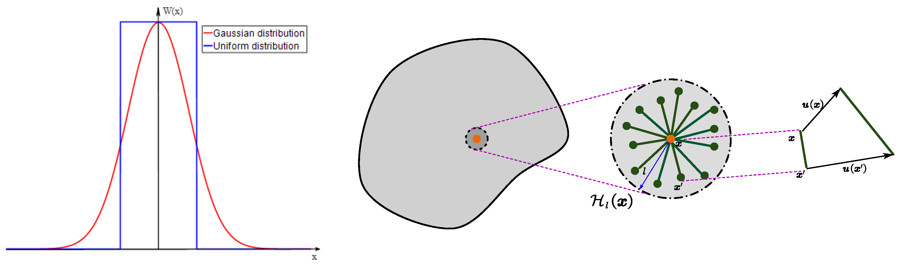
The Nonlocal Macro-Meso-scale Consistent Damage (NMMD) model adopts a nonlocal interaction approach where a material point interacts with neighboring points within a prescribed influence domain [25,29]. The crack process is represented at meso-scale by the relative motion and progressive break of material point pairs, and at macro-scale by the degradation of mechanical properties based on the macroscopic geometric damage evaluated by weighting of meso-scale damage. As illustrated in Figure 1 (showing spatial kernel function and relative motion), let ξ = x x be the reference vector between two material points and ν = ξ / | ξ | its unit direction vector.
The elongation of a point pair is defined as the relative displacement along the pair direction:
μ ( x , x , t ) = u x , t u x , t · ν
where u denotes the displacement vector. Only tensile elongation contributes to damage. Consequently, the tensile strain λ + along the direction of the point pair, after normalization, is obtained as
λ + ( x , x , t ) = < μ > + | ξ |
where < > + represents the Macaulay bracket (tensile part), ensuring that only positive (tensile) elongations are considered. The maximum over-elongation, which records the irreversible loading history, is defined as
χ ( x , x , t ) = max τ 0 , t [ | λ + ( x , x , τ ) λ c r | , 0 ]
where λ c r is the critical strain threshold, which can be determined by the uniaxial tensile strength f t and elastic modulus E [30].
Based on this history variable, the mesoscopic pairwise damage is defined as a monotonic function of χ :
ω ( x , x , t ) = ω ^ ( χ ( x , x , t ) ) = 1 exp ( γ χ )
where γ is the brittleness parameter controlling the post-threshold damage growth rate, which can be obtained by the following formula [30].
γ = A λ c r + A 8 G I c A λ c r 2 4 G I c A λ c r 2
where A = 12 k l / π , G I c is the fracture release energy for I type fracture, and k is bulk modulus. The mesoscopic damage of individual point pairs is then homogenized over the influence domain to define the macroscopic topological damage at material point x :
Ω ( x , t ) = D l ( x ) φ ( x , x ) ω ( x , x , t ) d V ( x )
Equation (6) defines the topological damage Ω as the weighted average of all pair damages inside the influence domain D l ( x ) .
φ ( x , x ) = 1 / v o l ( D l )
Equation (7) gives the uniformly distributed influence function φ ( x , x ) , where l is the influence radius. By construction, Ω varies from 0 for intact material to 1 for fully damaged material. Choose the following rational function as the energy degradation function:
g ( Ω ) = ( 1 Ω ) p 1 + q 1 ( 1 Ω ) p
where p and q are degradation parameters, requiring p 1 , q 0 , p + q > 1 . Parameters p and q have some intrinsic correlation with the influence radius [31], which control the shape of the energy degradation function and affect the softening behavior, damage localization, and final crack pattern [25]. For a given influence radius, they can be calibrated by the load–displacement curve of a three-point bending beam failure test [31]. The energy degradation function g ( Ω ) links the geometric topological damage to the loss of strain-energy storage capacity. Therefore, the dynamic equilibrium equation in the NMMD model can be written as
· g ( Ω ) ψ 0 ( ε ) ε + b = ρ u ¨ + c u ˙
where ρ is the material density, c the coefficient of viscosity, and b represents the body forces.
Remark 1 (Nonlocal Interaction and Crack Evolution). 
When failure occurs, the geometric compatibility equation is no longer strictly satisfied, resulting in a transfer of internal force transmission (i.e., stress release and stress redistribution). Local constitutive models cannot compensate for the force adjustment caused by geometric incompatibility. The NMMD model precisely reflects the force interruption caused by mesocrack initiation at the meso-scale and undertakes the stiffness degradation caused by force interruption at the macro level. Consequently, crack nucleation, growth, and branching can be naturally tracked during the failure process without additional fracture criterion.

2.2. Explicit Dynamics

Blast and impact loading contain abundant high-frequency stress-wave components. To improve the robustness of the transient solution and to couple efficiently with the evolving NMMD field, this study adopts an explicit time-integration scheme. The damped dynamic equilibrium equation is expressed as
M u ¨ ( t ) + C u ˙ ( t ) + K u ( t ) = R ( t )
{ K = e = 1 N e B e g ( Ω ) B T D e B d x = e = 1 N e K e M = e = 1 N e B e N T ρ N d x = e = 1 N e M e C = e = 1 N e B e N T c N d x = e = 1 N e C e R = e = 1 N e B e N T b   d x + e = 1 N e B t ¯ e N T f ¯   d s = e = 1 N e R e
where M , C , K , and R are the mass, damping, stiffness, and external load terms, respectively, and is the ensemble operator that assembles the element matrix into the overall matrix.
Equation (12) utilizes central-difference approximations for acceleration and velocity.
u ¨ n = u n + 1 2 u n + u n 1 Δ t 2 + O ( Δ t 2 ) u ˙ n = u n + 1 u n 1 2 Δ t + O ( Δ t 2 )
Substituting these approximations into Equation (10) yields the explicit displacement recurrence
u n + 1 = 2 u n u n 1 + Δ t 2 M 1 R n C u ˙ n K u n
The explicit formulation avoids solving a global linear system at each time step and is therefore efficient for strongly nonlinear transient crack-growth problems, provided that the time increment satisfies the stability requirement (CFL condition).
Δ t S h e min C d
where S is the stability coefficient, h e min is the characteristic element length, and c d is the velocity of expansion waves in materials. For isotropic materials, c d is given as
c d = E ρ 1 υ 2
where E is Young’s modulus and υ is Poisson’s ratio.
To consider the damping between the structure and the air medium, an additional 10~30% of the critical damping ratio is added to the material damping.

3. Numerical Examples and Discussion

The performance of the proposed explicit dynamic NMMD framework is assessed in this section using three benchmark problems. First, a single-edge-notched half-plate subjected to a non-stationary blast load is used to investigate mesh and time-step sensitivity. Second, a thick ring subjected to impulsive internal pressure is adopted to evaluate the capability of the framework to simulate multi-crack competition and fragmentation. Third, a hollow mortar cylinder containing a small borehole is analyzed to examine the effects of blast intensity, material heterogeneity, and damping on crack-network evolution.

3.1. Single-Edge-Notched Half Plate Under a Non-Stationary Blast Load

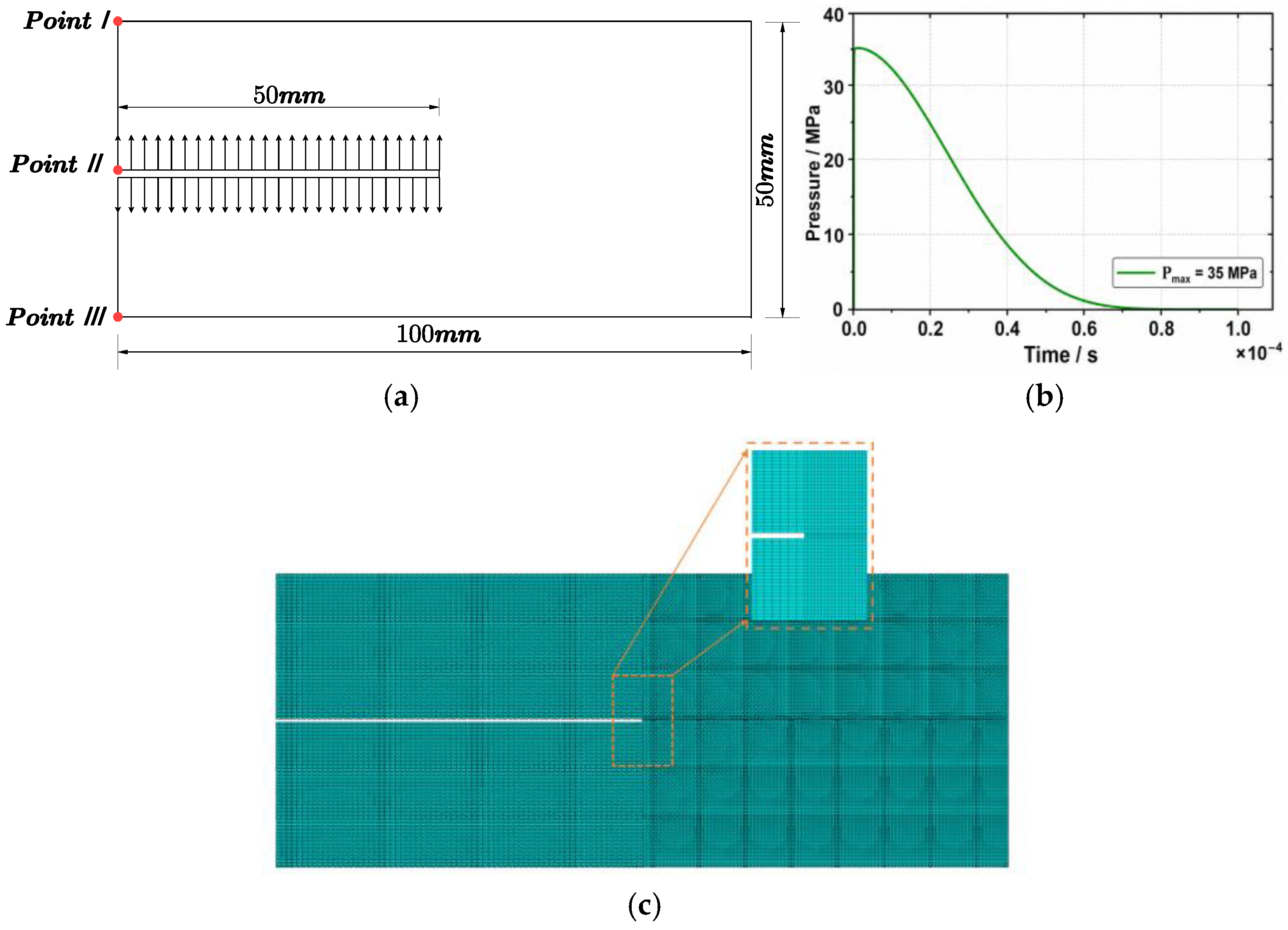
To assess the sensitivity to discretization parameters, a single-edge-notched half-plate subjected to a transient blast load was simulated. The geometry and a representative mesh are shown in Figure 2. A prefabricated crack of length 50 mm was located on the left edge. Material parameters were set as follows: Young’s modulus E = 3.2 × 10 4 MPa , Poisson’s ν = 0.2 , and density ρ = 2450 kg / m 3 . The NMMD influence radius was l = 0.001 m , with a critical strain threshold of λ c r = 1.8 × 10 4 . A blast pressure history with a peak value of P 0 = 35 MPa is applied to the upper and lower crack faces. Three discretization strategies, labeled A (coarse), B (medium), and C (fine), were employed for the convergence study, as detailed in Table 1. To isolate the intrinsic effects of mesh refinement and time step size on crack branching and global displacement responses, additional structural-air damping was not introduced, following common practice in dynamic fracture benchmark studies [32].
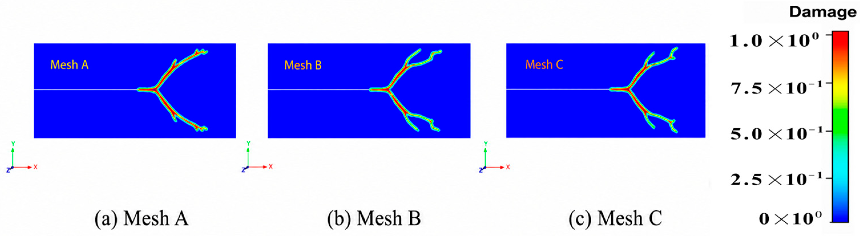
Key Observations on Spatial Discretization: The comparison among the three mesh strategies shows that mesh density does not act as a physical trigger of crack branching. Rather, it determines whether the discretized NMMD model can sufficiently resolve the nonlocal damage interaction and dynamic stress redistribution that are responsible for crack bifurcation. As shown in Figure 3, all three meshes reproduce the dominant crack propagation direction, indicating that the main fracture path is not governed by mesh orientation. However, the coarse mesh A produces a relatively simplified crack pattern with fewer secondary branches. This is because the characteristic element size is too large to adequately describe the fine-scale strain fluctuation and damage localization near the crack tip. As a result, potential secondary damage bands are spatially averaged and may be suppressed.
In contrast, the medium mesh B and fine mesh C produce very similar crack-branching morphologies. This indicates that, once the mesh is sufficiently refined, the nonlocal interaction domain contains enough discretization information to represent the competition among multiple damage bands. Therefore, the additional branches observed in the refined meshes should not be interpreted as artificial mesh-induced cracks. They should be understood as physically admissible branching paths that can only be resolved when the mesh density reaches the required resolution level.
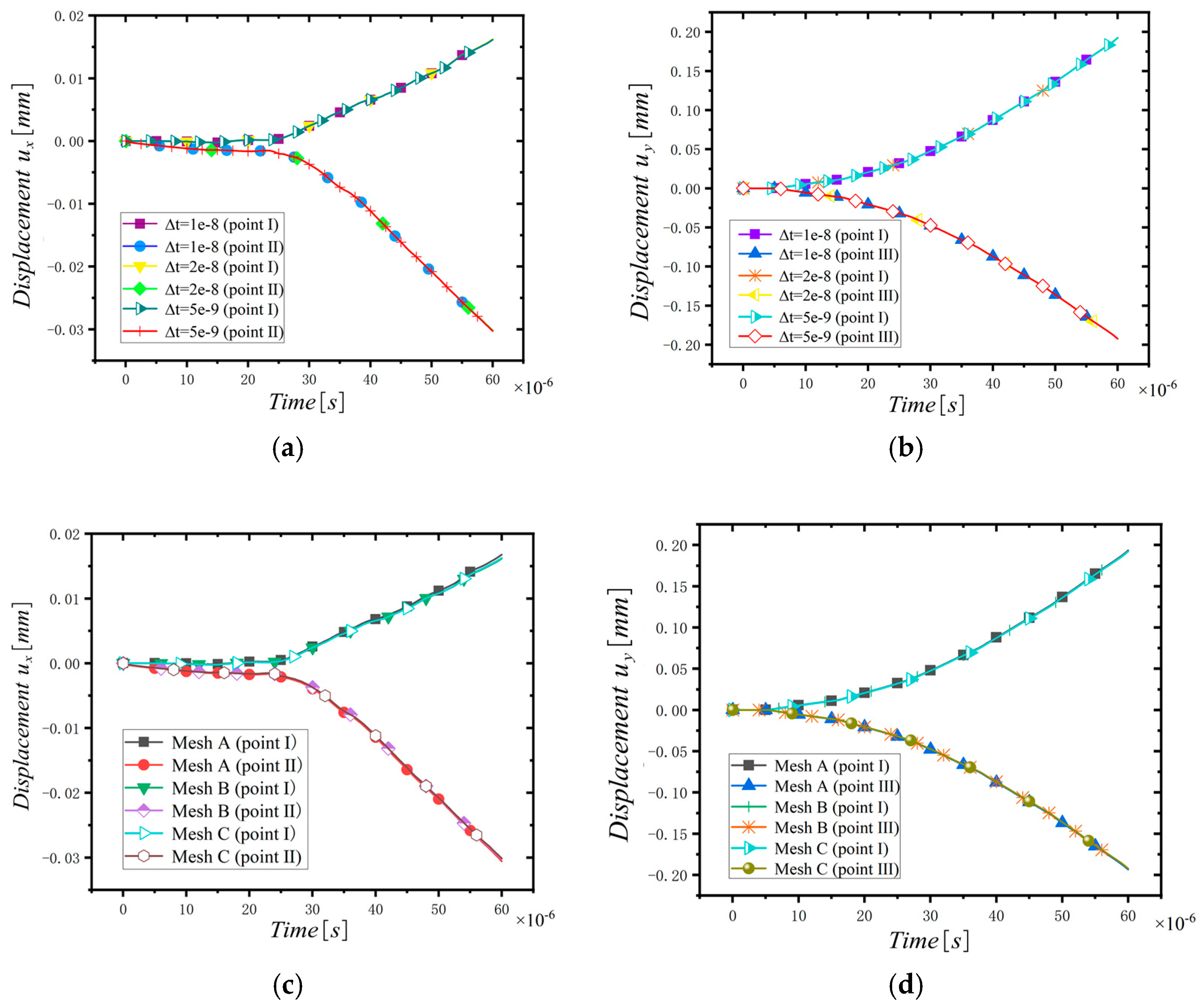
Key Observations on Temporal Discretization: To evaluate temporal convergence, displacement histories at three monitored points (I, II, III) were recorded for different time increments: Δ t = 2 × 10 8 s (coarse), 1 × 10 8 s (medium), and 5 × 10 9 s (fine). As shown in Figure 4, the displacement–time curves of points I and II were almost identical across all time increments. The response in the x-direction shows point II moving inward (negative displacement) while point I moves outward, reflecting the dynamic opening of the notch. The y-direction displacements for points I and III are nearly mirror-symmetric, as expected from the specimen’s geometry. The temporal insensitivity of the displacement response confirms the stability of the explicit integration scheme once the critical CFL condition is satisfied.
Synthesis: For the explicit NMMD framework, reliable predictions are achieved when both the spatial resolution is fine enough to capture nonlocal damage interactions and the temporal resolution complies with the explicit stability criterion. In particular, the present mesh-sensitivity analysis indicates that the characteristic mesh size should be less than 0.1 times the nonlocal intrinsic scale to adequately resolve crack branching. Under these conditions, the model shows low sensitivity to further mesh refinement and small time-step variations for global displacement responses.

3.2. Thick Ring Under Impulsive Internal Pressure

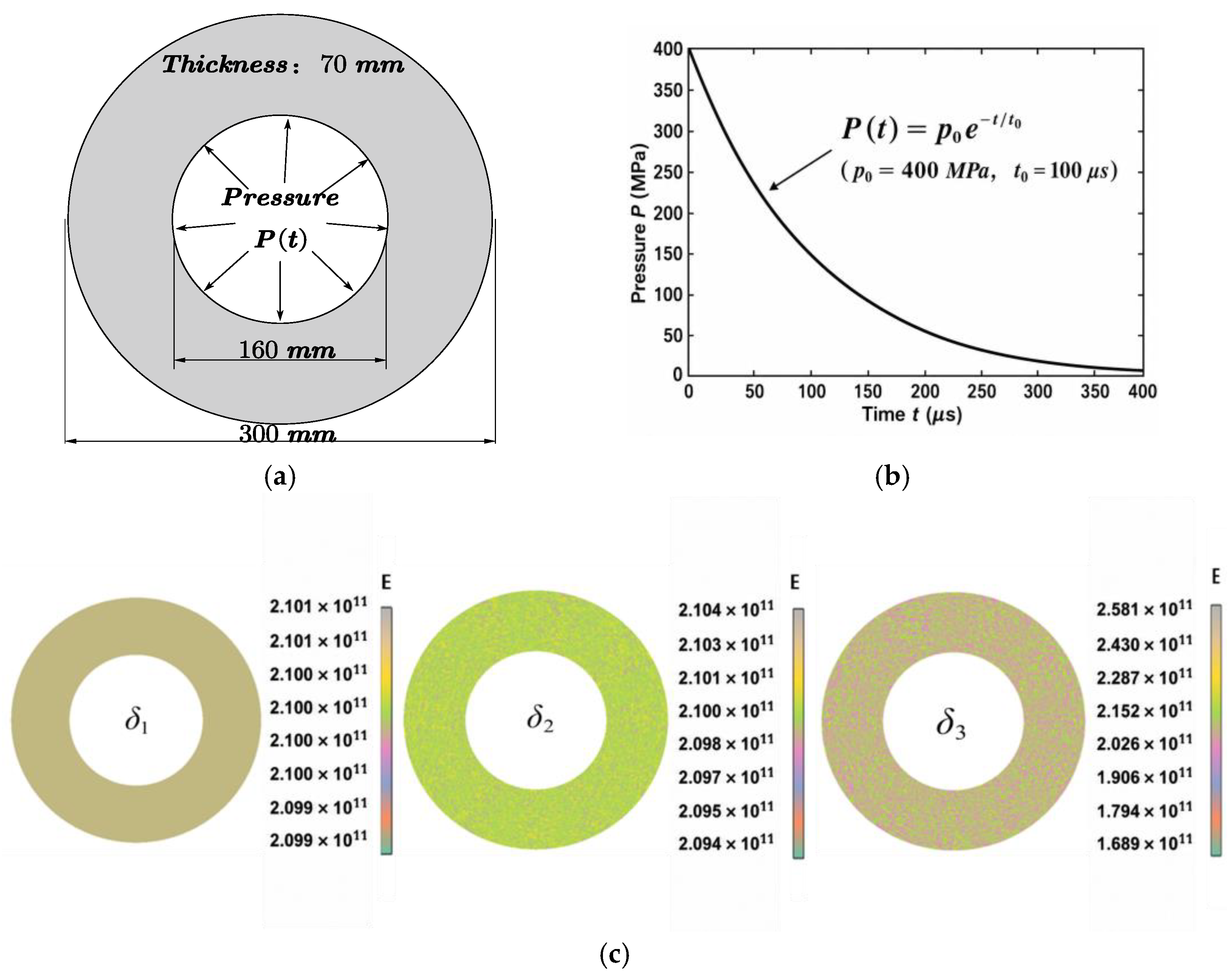
A thick ring subjected to an impulsive internal pressure is a classical benchmark for evaluating a model’s ability to simulate simultaneous crack initiation, propagation, competition, and final fragmentation. The ring dimensions were R i n = 80 mm (inner radius), and R o u t = 150 mm (outer radius). The material properties were set to E = 210 GPa , ν = 0.3 , ρ = 7850 kg / m 3 (Song and Belytschko 2009) [14], and cohesive strength 850 MPa . The NMMD model used an influence radius l = 0.003   m and the critical threshold was λ c r = 1.14 × 10 5 . An impulsive internal pressure P ( t ) = p 0 e x p ( t / t 0 ) was applied on the inner boundary, with p 0 = 400 MPa and t 0 = 100   μ s .
To introduce realistic heterogeneity, Young’s modulus was modeled as a spatially correlated random field generated using the Box–Muller method. Three standard deviation levels of the random field ( δ 1 = 1 × 10 6 GPa , δ 2 = 1 × 10 8 GPa , and δ 3 = 1 × 10 10 GPa ), as shown in Figure 5, were analyzed.
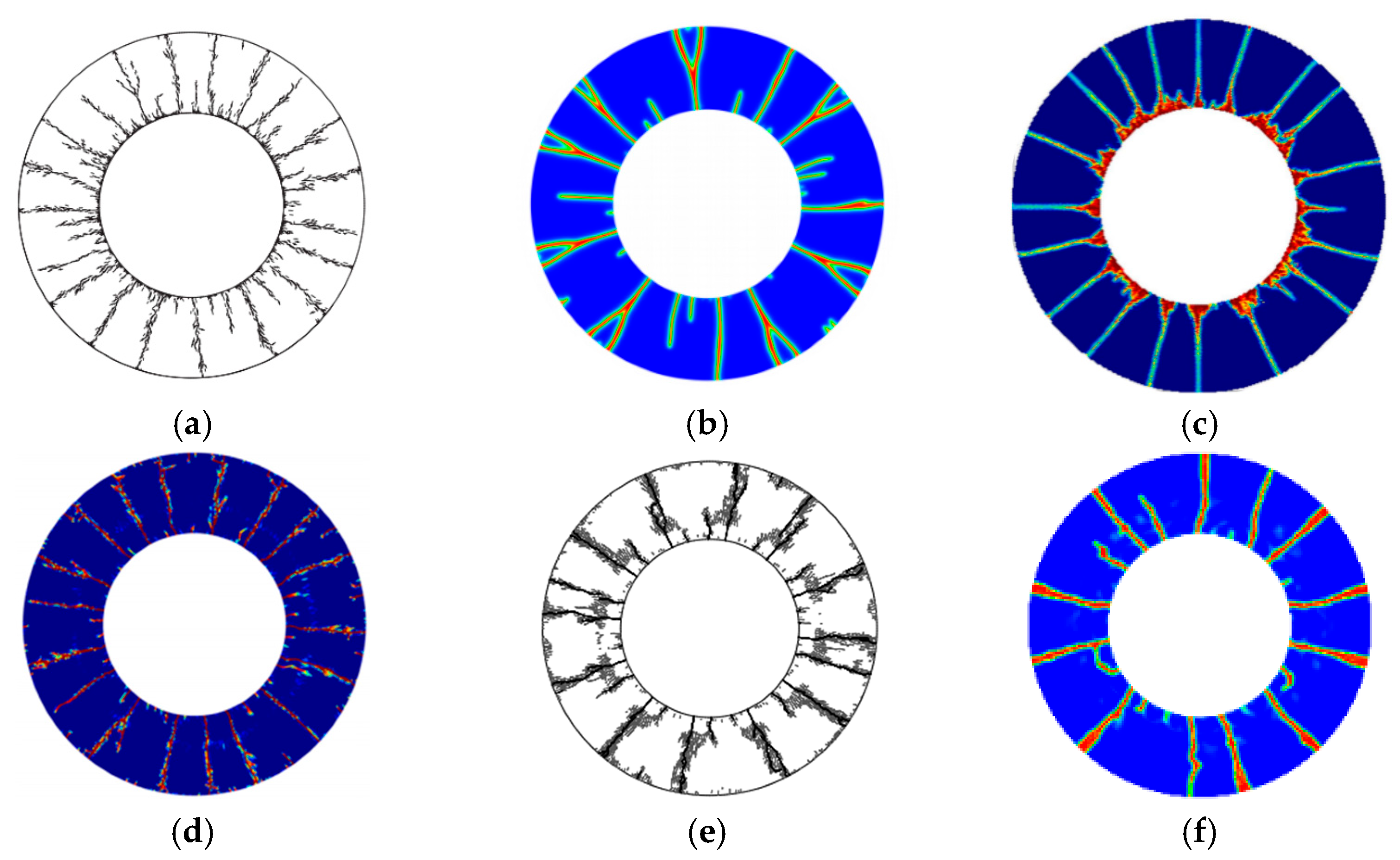
Comparison with Other Numerical Methods: Figure 6 compares the predicted crack pattern using the present NMMD method with results from several established numerical methods in the literature, including the cracking-node method [14], phase-field method [13], peridynamic method [23], a revisited local-damage method [23], and a cohesive fracture method [15]. While all methods capture the fundamental physical phenomenon—initiation of radial cracks from the inner surface, and their propagation and eventual fragmentation—subtle differences in the evolution and selection of crack paths are evident.
The NMMD method predicts a slightly lower number of dominant crack paths and larger fragments. As shown in Table 2, the number of large fragments predicted by the NMMD method is between 11 and 12, whereas other methods report numbers ranging from 11 to 24, contingent upon their respective fragmentation criteria and discretization.
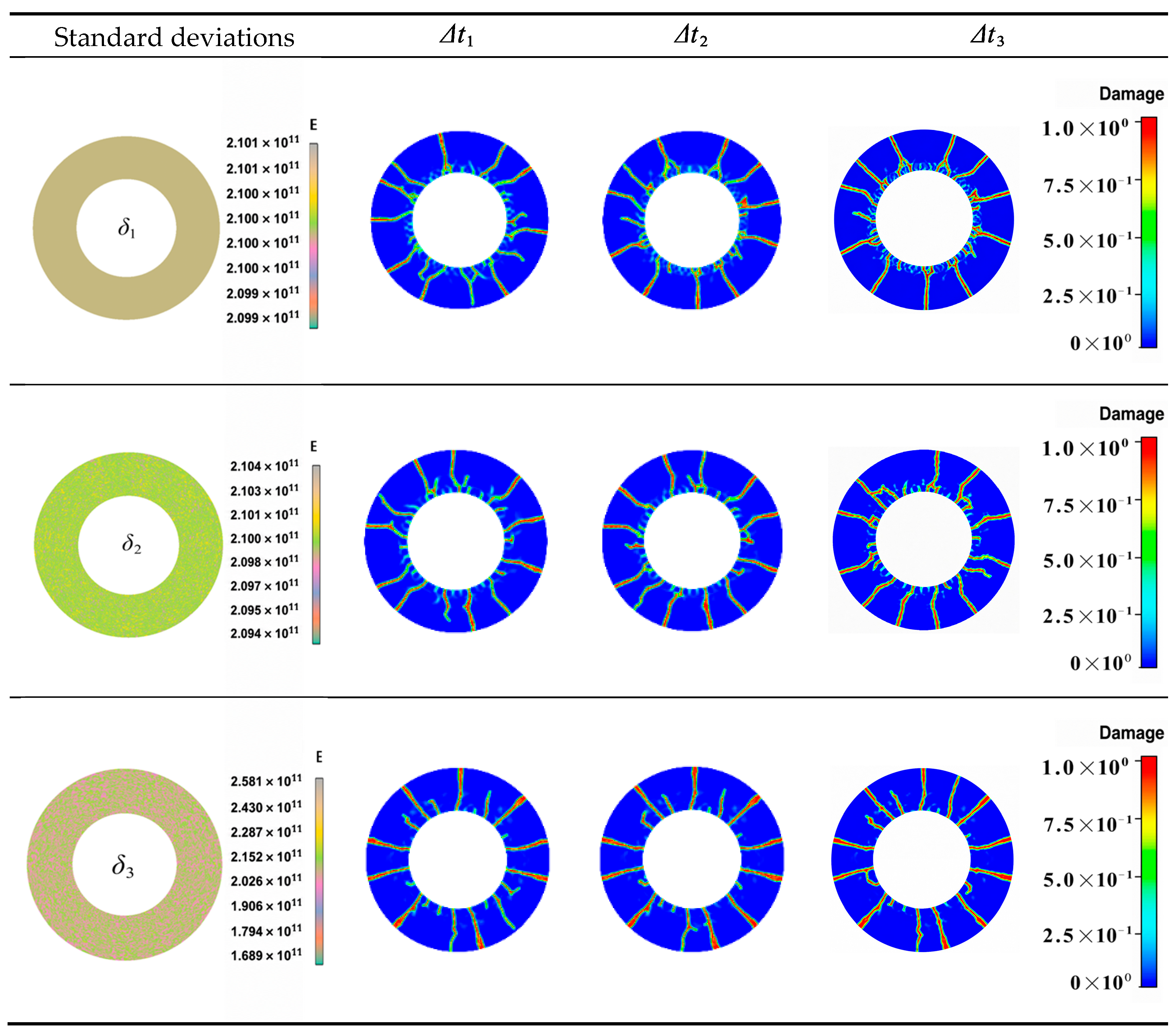
Effects of Time Step and Material Heterogeneity: Figure 7 illustrates the combined effect of time step ( Δ t = 5 × 10 9 s , 7 × 10 9 s , and 1 × 10 8 s ) and material heterogeneity (standard deviation, δ ). The following observations are made:
  • Effect of Time Step ( Δ t ): The fundamental framework of the dominant crack pattern remains largely unchanged with varying time increments. The primary influence of a refined time step is an improved resolution of local crack-branching details, as high-frequency crack bifurcation processes near crack tips are captured more precisely.
  • Effect of Material Heterogeneity ( δ ): Increasing the standard deviation of the random field intensifies local material fluctuations, directly affecting crack competition. Higher heterogeneity disrupts crack path symmetry, increases path variability, and allows some secondary cracks—that might arrest in a more homogeneous medium—to propagate and eventually become dominant. This underscores that the fragmentation pattern is strongly governed by the inherent spatial variability of the material’s resistance.
Figure 7. Thick-ring results for different time increments and standard deviations of the random elastic-modulus E (GPa) field.
Modelling 07 00101 g007

3.3. Hollow Mortar Cylinder with a Small Borehole

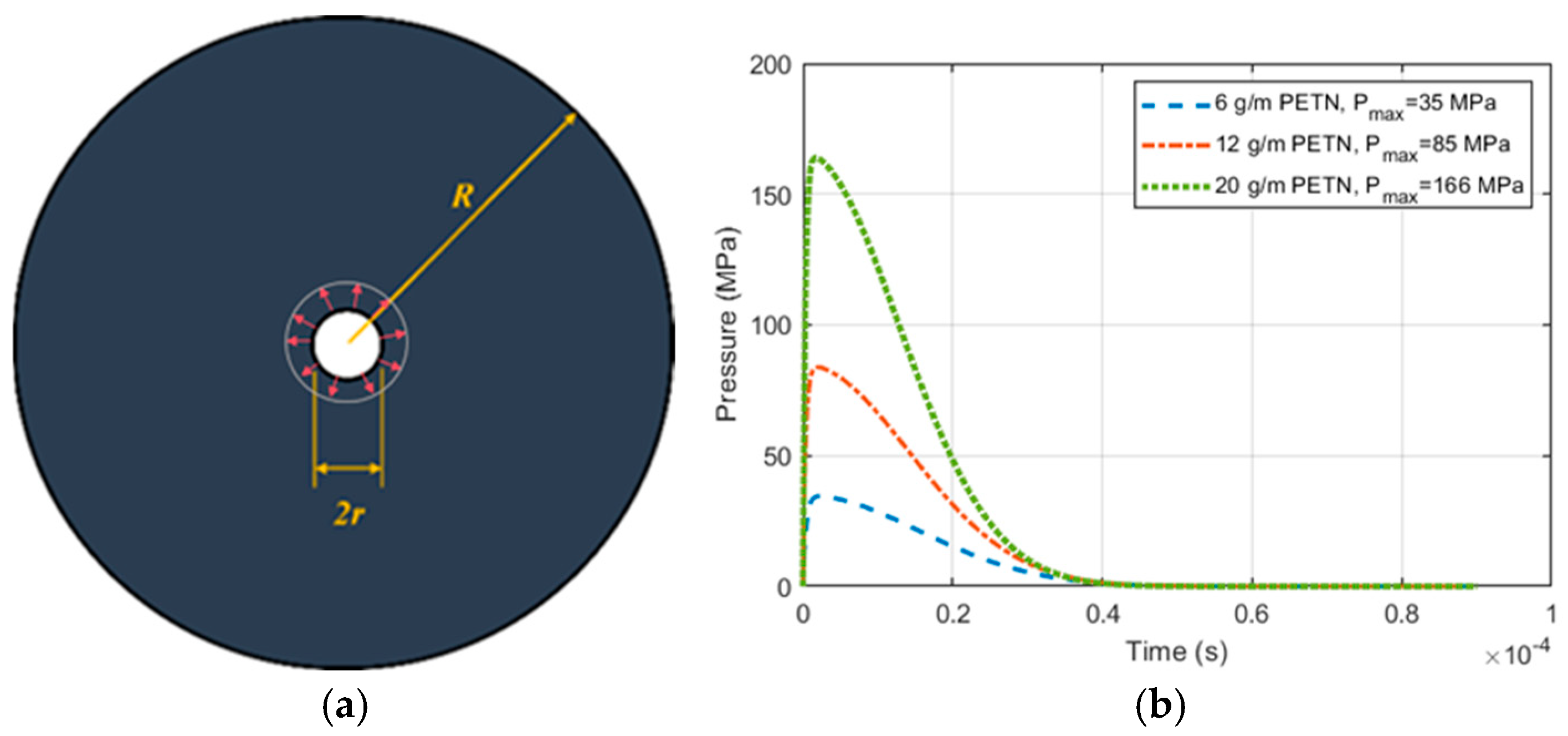
A hollow mortar cylinder was modeled to simulate crack evolution under blasting conditions similar to small-scale blast tests. A plane-strain assumption was adopted, with cylinder diameter R = 150 mm and borehole radius r = 5 mm . PETN charge concentrations of 6, 12, and 20 g/m were considered, translating to approximate peak borehole pressures of 35, 85, and 166 MPa, as shown in Figure 8, respectively. The pressure history at the borehole wall was prescribed using the analytical function proposed by Triviño et al. [32]: P ( t ) = P peak · e { [ b u ( t t u ) ] 2 n } · e { [ b d ( t t d ) ] 2 } . In the equation, b u , t u , n , b d and t d define the rise and fall of the pressure function, b u = b d / b r a t i o and b r a t i o 2 . Here, b d and b u are related to the maximum decay rate m d and the maximum rise rate m u . The parameter t u = [ ln ( α 1 ) ] 1 / ( 2 n ) / b u and t d = [ ln ( α 1 ) ] 1 / ( 2 n ) [ ln ( 1 α 2 ) ] 1 / ( 2 n ) / b u . The parameters for the function are listed in Table 3. Mortar properties were E = 12.2 GPa , ν = 0.23 , and ρ = 1660 kg / m 3 . The time increment is 2 × 10 8   s . The NMMD parameters were λ c r = 0.356 × 10 6 , influence radius l = 0.0015   m , and degradation parameters p = 5 and q = 0 . Unless otherwise stated, the damping coefficient was c = 30   Pa · s .
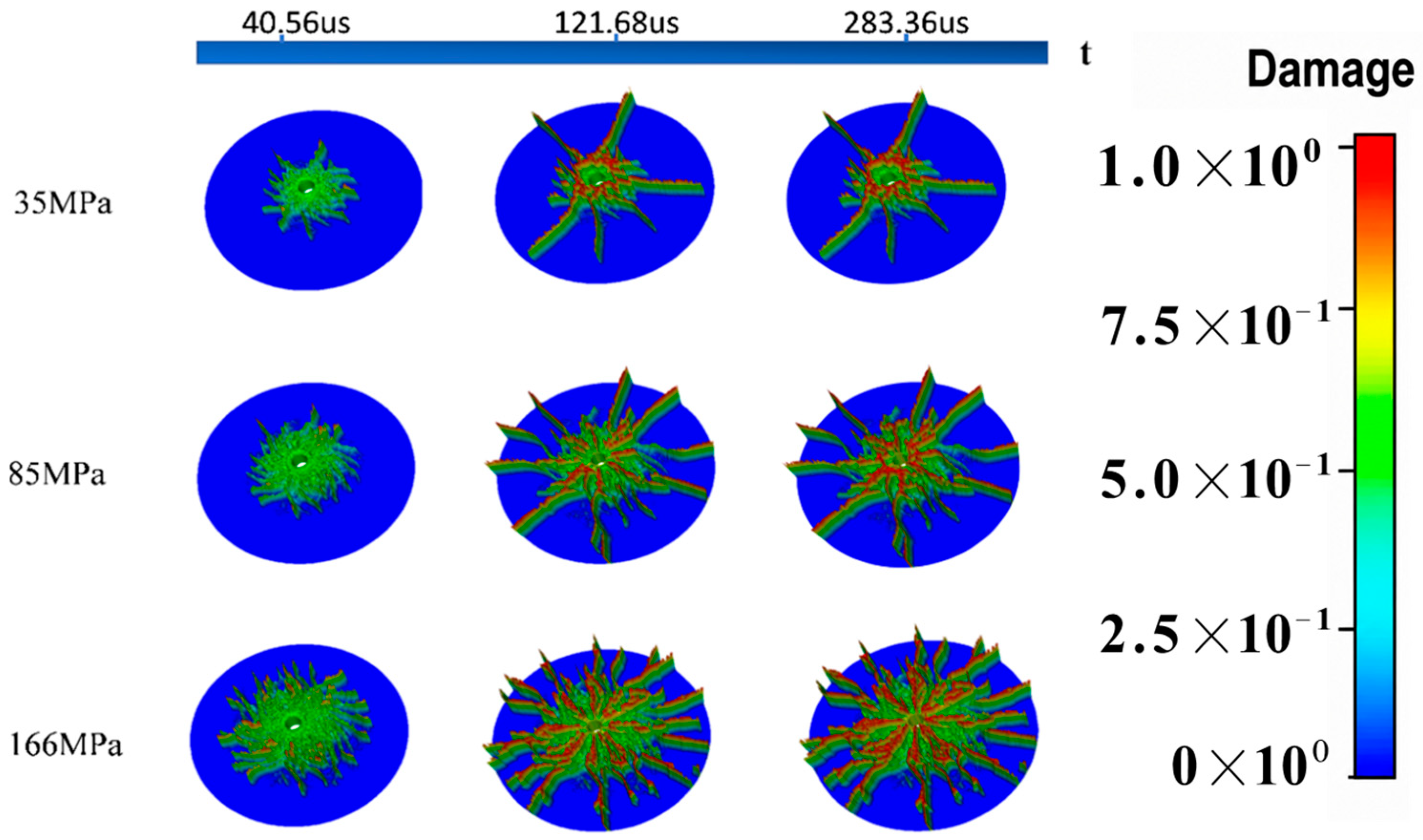
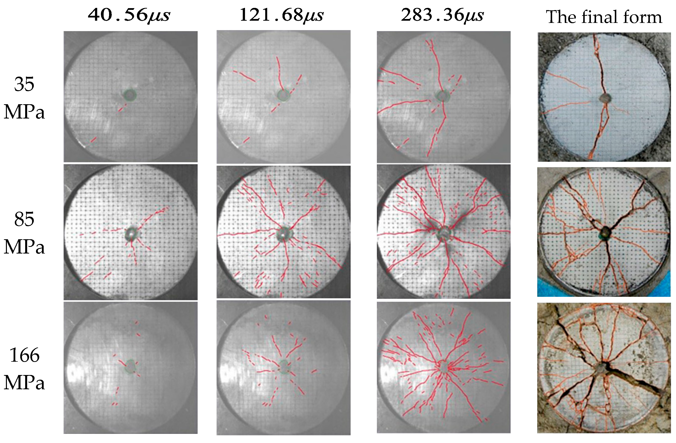
Crack Evolution with Increasing Blast Load: Figure 9 shows the predicted damage evolution under the three blast-pressure levels. A two-stage evolution pattern is observed: (1) rapid expansion of major radial cracks accompanied by pronounced branching and (2) a subsequent stabilization stage, during which damage is mainly intensified within existing cracks. This trend is in good agreement with high-speed camera images reported in experimental studies [10,32], which are presented in Figure 10 for comparison. At 35 MPa, only a few long radial cracks are formed. At 85 MPa, more radial cracks are observed, and branching becomes more pronounced. At 166 MPa, a dense crack network is generated, wide crack channels are formed, and distinct fragmentation features are observed, indicating a transition from stress-concentration-controlled fracture to energy-dominated failure.
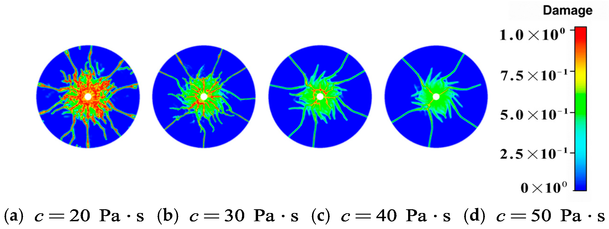
Effect of Damping: Damping critically affects the post-peak dynamic response and energy dissipation. Four damping coefficients (c = 20, 30, 40, 50 Pa · s ) were investigated for the 85 MPa case (Figure 11). Increased damping results in fewer major cracks, less branching, and a more localized damage zone. A damping coefficient within the range of c = 20 30   Pa · s provides a balanced prediction of crack number, pattern, and propagation scale for the current model and material parameters.
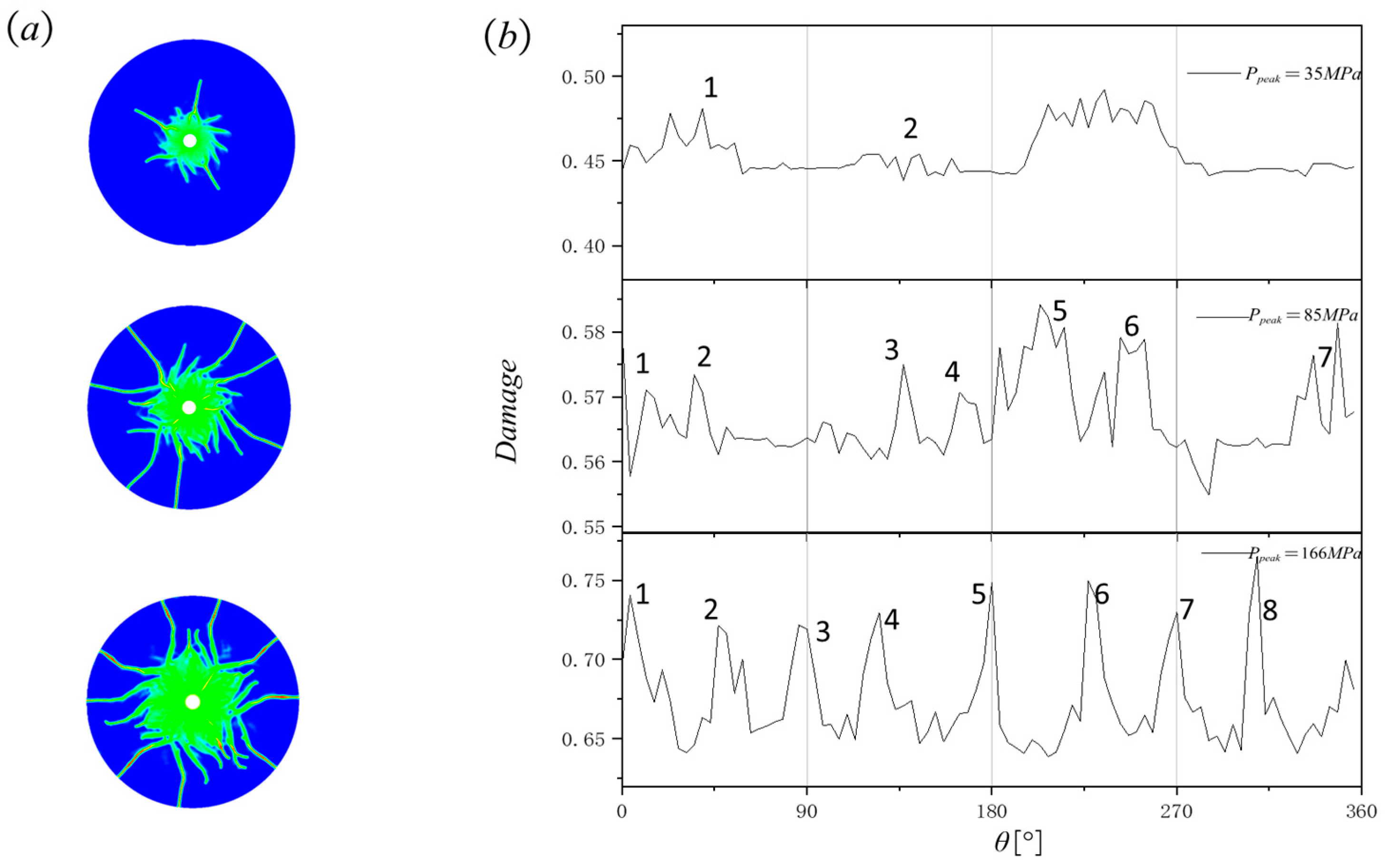
Influence of Peak Load with Constant Damping: Fixing the damping coefficient at c = 40   Pa · s , the effect of peak load 85 MPa on the final crack pattern was analyzed. As shown in Figure 12a, the number of primary cracks increased with load intensity. The location of the first few main cracks was similar across all load levels, but additional cracks nucleated and propagated, often along the angular bisectors between the primary cracks, as the load increased. The circumferential distribution of damage around the borehole (Figure 12b) reveals that the damage peaks correspond to main crack initiation points, and the amplitude of circumferential fluctuation intensifies with higher loads, reflecting stronger stress concentration and non-uniform failure.
In the NMMD model, the damage variable Ω is a continuous field rather than a binary crack indicator. Crack initiation is governed by the critical strain threshold, while Ω = 1 represents complete stiffness degradation or a fully developed crack. Therefore, a visible crack path does not necessarily require the damage value to be exactly equal to 1; localized high-damage bands indicate crack process zones or developing cracks. Figure 12b shows the damage distribution around the borehole, which should be interpreted as circumferential damage concentration rather than a direct binary crack map. The region close to the borehole mainly corresponds to a crushed zone, where severe compressive damage occurs but distinct tensile cracks are not clearly separated. Outside the crushed zone, clear cracks are identified only where damage localizes into narrow radial bands. In regions far from the crushed zone, where the damage value remains low and no localization band appears, no distinct crack is considered to occur.

4. Conclusions

In this study, an explicit dynamic computational framework based on the Nonlocal Macro-Meso-scale Consistent Damage (NMMD) model was developed to simulate the complex evolution of multiple cracks in quasi-brittle materials subjected to blast loading. Through a systematic analysis of three benchmark examples, the predictive capability and numerical characteristics of the proposed framework were evaluated, yielding the following key findings:
(1)
Framework Reliability and Discretization Convergence
It is demonstrated by the benchmark analyses of the single-edge-notched plate and thick-ring fragmentation problem that dynamic fracture processes, including crack initiation, propagation, branching, and coalescence, can be reliably predicted by the proposed explicit NMMD framework without the need for remeshing or explicit crack tracking. However, this reliability is contingent on the satisfaction of two critical computational requirements: (1) the spatial mesh density must exceed a minimum resolution threshold so that nonlocal interactions and material heterogeneity can be adequately resolved, and (2) the time step must satisfy the explicit stability criterion, namely the Courant–Friedrichs–Lewy (CFL) condition. Once these convergence criteria are met, the predicted crack paths and global structural responses show limited sensitivity to further spatial and temporal discretization refinement.
(2)
Crack Pattern and Fragmentation Characteristics
Compared with other numerical methods, the NMMD model tends to predict fewer but more dominant crack paths, resulting in a conservative estimation of the number of fragments and, consequently, larger predicted fragment sizes. This indicates that the principal-crack selection mechanism during dynamic fracture competition is effectively captured by the model.
(3)
Key Factors Influencing Crack Evolution
The influence of several key physical and computational parameters was elucidated:
  • Material Heterogeneity: As a key factor controlling crack-path selection, increased material heterogeneity enhances local strain concentration and damage localization. As a result, crack-field symmetry is disrupted, path variability is amplified, and secondary cracks that might otherwise arrest in a homogeneous medium are allowed to evolve into dominant crack paths. This finding suggests that blast-driven fracture is governed not only by the applied loading but also by the spatial distribution of local material resistance.
  • Blast Load Intensity: For the hollow mortar cylinder, radial crack multiplication, branching intensity, and crack-network connectivity are enhanced by increasing blast peak pressure, indicating a transition from stress-concentration-controlled fracture to energy-dominated failure.
  • Damping: The damping coefficient primarily regulates the post-peak dynamic response. Larger damping values reduce crack multiplicity, branching intensity, and the spatial extent of propagation, shifting the failure pattern from a dense, widely distributed crack network to a more sparse and localized system.
Overall, the developed explicit NMMD framework can be regarded as a robust and practical computational tool for simulating complex blast-induced multiple-cracking processes in quasi-brittle materials. By linking macro-scale structural responses with meso-scale damage mechanisms, the framework provides useful insights for the analysis and design of structures subjected to blast and impact loading.

Author Contributions

Program implementation, simulation, and writing—original draft, Q.Y.; conceptualization, methodology, and writing—review and editing, X.X. and G.L. All authors have read and agreed to the published version of the manuscript.

Funding

This research was funded by the National Natural Science Foundation of China (No. 12202314).

Data Availability Statement

Dataset available on request from the authors.

Conflicts of Interest

The authors declare no conflicts of interest.

Nomenclature

x , x Material points in the reference configuration
ξ Reference vector between two material points
ν Unit direction vector of a material point pair
u Displacement vector
λ + Tensile strain
χ Maximum over-elongation
ω Mesoscopic pairwise damage
Ω Macroscopic topological damage
Φ Spatial influence function
p , q Degradation parameters
g Energy degradation function
E Young’s modulus
ν Poisson’s ratio
ρ Material density
b Body force vector
c Viscosity or damping coefficient
M Mass matrix
C Damping matrix
K Stiffness matrix
F External load vector
A Finite-element assembly operator
c d Expansion wave velocity

References

  1. Lu, Y. Impact on reinforced concrete structures. In Encyclopedia of Continuum Mechanics; Springer: Berlin/Heidelberg, Germany, 2020; pp. 1309–1332. [Google Scholar]
  2. Zhang, C.; Gholipour, G.; Mousavi, A.A. Blast loads induced responses of RC structural members: State-of-the-art review. Compos. Part B Eng. 2020, 195, 108066. [Google Scholar] [CrossRef] [Scilit]
  3. Cadoni, E.; Caldentey, A.P.; Colombo, M.; Dancygier, A.N.; di Prisco, M.; Grisaro, H.; Martinelli, P.; Ožbolt, J.; Pająk, M.; Weerheijm, J. State-of-the-art on impact and explosion behaviour of concrete structures: Report of RILEM TC 288-IEC. Mater. Struct. 2025, 58, 62. [Google Scholar] [CrossRef] [Scilit]
  4. Fan, H.; Yu, H.; Ma, H. Dynamic increase factor (DIF) of concrete with SHPB tests: Review and systematic analysis. J. Build. Eng. 2023, 79, 107666. [Google Scholar] [CrossRef] [Scilit]
  5. Lian, H.; Sun, X.; Yu, Z.; Lian, Y.; Xie, L.; Long, A.; Guan, Z. Study on the dynamic fracture properties and size effect of concrete based on DIC technology. Eng. Fract. Mech. 2022, 274, 108789. [Google Scholar] [CrossRef] [Scilit]
  6. Trivino, L.F.; Mohanty, B. Assessment of crack initiation and propagation in rock from explosion-induced stress waves and gas expansion by cross-hole seismometry and FEM-DEM method. Int. J. Rock Mech. Min. Sci. 2015, 77, 287–299. [Google Scholar] [CrossRef] [Scilit]
  7. Onederra, I.; Esen, S.; Jankovic, A. Estimation of fines generated by blasting—Applications for the mining and quarrying industries. Min. Technol. 2004, 113, A237–A245. [Google Scholar] [CrossRef] [Scilit]
  8. Wang, S.; Wang, L.; Wang, Y. Influence of material heterogeneity on the blast-induced crack initiation and propagation in brittle rock. Comput. Geotech. 2023, 155, 105203. [Google Scholar] [CrossRef] [Scilit]
  9. Yi, C.; Johansson, D.; Greberg, J. Effects of in-situ stresses on the fracturing of rock by blasting. Comput. Geotech. 2018, 104, 321–330. [Google Scholar] [CrossRef] [Scilit]
  10. Iravani, A.; Kukolj, I.; Ouchterlony, F.; Antretter, T.; Astrom, J.A. Modelling blast fragmentation of cylinders of mortar and rock. In Fragblast 12: 12th International Symposium on Rock Fragmentation by Blasting; Schunnesson, H., Johansson, D., Eds.; Luleå University of Technology: Luleå, Sweden, 2018; pp. 597–610. [Google Scholar]
  11. Kukolj, I.; Iravani, A.; Ouchterlony, F.; Antretter, T.; Astrom, J.A. Filming blast fragmentation of rock and mortar cylinders. In Fragblast 12: 12th International Symposium on Rock Fragmentation by Blasting; Schunnesson, H., Johansson, D., Eds.; Luleå University of Technology: Luleå, Sweden, 2018; pp. 483–494. [Google Scholar]
  12. Kukolj, I.; Iravani, A.; Ouchterlony, F. Using small-scale blast tests and numerical modelling to trace the origin of fines generated in blasting. BHM Berg Hüttenmännische Monatshefte 2018, 163, 427–436. [Google Scholar] [CrossRef] [Scilit]
  13. Geelen, R.J.; Liu, Y.; Hu, T.; Tupek, M.R.; Dolbow, J.E. A phase-field formulation for dynamic cohesive fracture. Comput. Methods Appl. Mech. Eng. 2019, 348, 680–711. [Google Scholar] [CrossRef] [Scilit]
  14. Song, J.H.; Belytschko, T. Cracking node method for dynamic fracture with finite elements. Int. J. Numer. Methods Eng. 2009, 77, 360–385. [Google Scholar] [CrossRef] [Scilit]
  15. Hirmand, M.R.; Papoulia, K.D. Block coordinate descent energy minimization for dynamic cohesive fracture. Comput. Methods Appl. Mech. Eng. 2019, 354, 663–688. [Google Scholar] [CrossRef] [Scilit]
  16. Bui, T.Q.; Tran, H.T.; Hu, X.F.; Wu, C.T. Simulation of dynamic brittle and quasi-brittle fracture: A revisited local damage approach. Int. J. Fract. 2022, 236, 59–85. [Google Scholar] [CrossRef] [Scilit]
  17. Bourdin, B.; Francfort, G.A.; Marigo, J.J. Numerical experiments in revisited brittle fracture. J. Mech. Phys. Solids 2000, 48, 797–826. [Google Scholar] [CrossRef] [Scilit]
  18. Wu, J.Y. A unified phase-field theory for the mechanics of damage and quasi-brittle failure. J. Mech. Phys. Solids 2017, 103, 72–99. [Google Scholar] [CrossRef] [Scilit]
  19. Silling, S.A. Reformulation of elasticity theory for discontinuities and long-range forces. J. Mech. Phys. Solids 2000, 48, 175–209. [Google Scholar] [CrossRef] [Scilit]
  20. Silling, S.A.; Askari, E. A meshfree method based on the peridynamic model of solid mechanics. Comput. Struct. 2005, 83, 1526–1535. [Google Scholar] [CrossRef] [Scilit]
  21. Silling, S.A.; Lehoucq, R.B. Peridynamic theory of solid mechanics. Adv. Appl. Mech. 2010, 44, 73–168. [Google Scholar]
  22. Madenci, E.; Roy, P.; Behera, D. Advances in Peridynamics; Springer International Publishing: Cham, Switzerland, 2022. [Google Scholar]
  23. Niu, Y.; Zhou, X.; Chen, J. Numerical study on dynamic cracking characteristic and mechanism of quasi-brittle materials under impulsive loading. Theor. Appl. Fract. Mech. 2024, 131, 104356. [Google Scholar] [CrossRef] [Scilit]
  24. Paulino, G.H.; Park, K.; Celes, W.; Espinha, R. Adaptive dynamic cohesive fracture simulation using nodal perturbation and edge-swap operators. Int. J. Numer. Methods Eng. 2010, 84, 1303–1343. [Google Scholar] [CrossRef] [Scilit]
  25. Lu, G.; Chen, J. A new nonlocal macro-meso-scale consistent damage model for crack modeling of quasi-brittle materials. Comput. Methods Appl. Mech. Eng. 2020, 362, 112802. [Google Scholar] [CrossRef] [Scilit]
  26. Chen, J.; Ren, Y.; Lu, G. Meso-scale physical modeling of energetic degradation function in the nonlocal macro-meso-scale consistent damage model for quasi-brittle materials. Comput. Methods Appl. Mech. Eng. 2021, 374, 113588. [Google Scholar] [CrossRef] [Scilit]
  27. Ren, Y.; Chen, J.; Lu, G. A structured deformation driven nonlocal macro-meso-scale consistent damage model for the compression/shear dominate failure simulation of quasi-brittle materials. Comput. Methods Appl. Mech. Eng. 2023, 410, 115945. [Google Scholar] [CrossRef] [Scilit]
  28. Ren, Y.; Lu, G.; Chen, J. Physically consistent nonlocal macro-meso-scale damage model for quasi-brittle materials: A unified multiscale perspective. Int. J. Solids Struct. 2024, 293, 112738. [Google Scholar] [CrossRef] [Scilit]
  29. Lu, G.; Chen, J.; Ren, Y. New insights into fracture and cracking simulation of quasi-brittle materials based on the NMMD model. Comput. Methods Appl. Mech. Eng. 2024, 432, 117347. [Google Scholar] [CrossRef] [Scilit]
  30. Lv, W.; Lu, G.; Xia, X.; Gu, X.; Zhang, Q. Energy degradation mode in nonlocal Macro-Meso-Scale damage consistent model for quasi-brittle materials. Theor. Appl. Fract. Mech. 2024, 130, 104288. [Google Scholar] [CrossRef] [Scilit]
  31. Lu, G.; Chen, J. Dynamic cracking simulation by the nonlocal macro-mesoscale damage model for isotropic materials. Int. J. Numer. Methods Eng. 2021, 122, 3070–3099. [Google Scholar] [CrossRef] [Scilit]
  32. Triviño, L.F.; Mohanty, B.; Munjiza, A. Seismic radiation patterns from cylindrical explosive charges by analytical and combined finite-discrete element methods. In Rock Fragmentation by Blasting: Proceedings of the 9th International Symposium on Rock Fragmentation by Blasting (Fragblast 9); Sanchidrián, J.A., Ed.; Francis: London, UK, 2009; pp. 415–426. [Google Scholar]
Figure 1. Spatial kernel function and relative motion of a material point pair, the dashed lines indicate the enlarged local interaction region.
Modelling 07 00101 g001
Figure 2. Geometry, loading history, and representative mesh for the single-edge-notched half plate: (a) geometric configuration and measurement points; (b) blast pressure history; (c) representative computational mesh.
Modelling 07 00101 g002
Figure 3. Damage distributions obtained with different meshes.
Modelling 07 00101 g003
Figure 4. Displacement−time responses of monitored points under different time increments and mesh densities: (a,b) displacement responses under different time increments; (c,d) displacement responses under different mesh densities.
Modelling 07 00101 g004
Figure 5. Representative random-field samples of Young’s modulus E (GPa). ( δ 1 = 1 × 10 6 GPa , δ 2 = 1 × 10 8 GPa , δ 3 = 1 × 10 10 GPa ).
Modelling 07 00101 g005
Figure 6. Comparison of thick-ring crack patterns obtained with different numerical methods. (a) Cracking-node method [14]; (b) Phase-field method [13]; (c) Peridynamic method [23]; (d) Local-damage method [16]; (e) Cohesive fracture method [15]; (f) NMMD method.
Modelling 07 00101 g006
Figure 8. Plane-strain borehole model and pressure histories for the three peak pressures: (a) schematic of the plane-strain borehole model, showing the borehole radius r, outer model radius R, and applied radial loading region; (b) pressure−time histories corresponding to three PETN charge masses with peak pressures of 35, 85, and 166 MPa.
Modelling 07 00101 g008
Figure 9. Damage evolution at different stages for three peak pressures, where t denotes time.
Modelling 07 00101 g009
Figure 10. Experimental high-speed end-face images for the three peak pressures.
Modelling 07 00101 g010
Figure 11. Damage patterns at t = 200 μs for different damping coefficients under a peak pressure of 85 MPa .
Modelling 07 00101 g011
Figure 12. Damage distribution around the hole at c = 40 Pa·s and Ppeak = 85 MPa (a) damage distribution around the hole; (b) circumferential damage distribution along an inner circular path around the hole.
Modelling 07 00101 g012
Table 1. Mesh strategy for the single-edge-notched half plate.
M e s h N e h f m m Δ t s
A31,9170.1671 × 10−8
B70,5500.1001 × 10−8
C116,3100.0831 × 10−8
Table 2. Number of large fragments obtained by different numerical methods.
MethodNumber of Large Fragments
Cracking node method18 (10,443), 19 (32,383), 20 (75,202)
Adaptive dynamic cohesive method20, 23, 24
Phase-field method13 (218,400), 11 (400,000), 12 (728,000)
Revised local-damage method19 (9325), 19 (14,550), 18 (25,839), 18 (57,945)
Cohesive fracture method14 (20,434), 15 (30,258), 16 (40,654)
Peridynamic method18
NMMD method11, 12
Table 3. Parameters of the borehole pressure function.
Parameter m u m d b r a t i o α 1 α 2
Value45 × 10525 × 103210−710−2
Disclaimer/Publisher’s Note: The statements, opinions and data contained in all publications are solely those of the individual author(s) and contributor(s) and not of MDPI and/or the editor(s). MDPI and/or the editor(s) disclaim responsibility for any injury to people or property resulting from any ideas, methods, instructions or products referred to in the content.