Article

Zernike Correction and Multi-Objective Optimization of Multi-Layer Dual-Scale Nano-Coupled Anti-Reflective Coatings

1
School of Media Engineering, Communication University of Zhejiang, Hangzhou 310018, China
2
Key Laboratory of Film and Television Media Technology of Zhejiang Province, Hangzhou 310018, China
*
Author to whom correspondence should be addressed.
Modelling 2026, 7(1), 29; https://doi.org/10.3390/modelling7010029
Submission received: 27 December 2025 / Revised: 23 January 2026 / Accepted: 27 January 2026 / Published: 30 January 2026

Abstract

In high-precision optical systems such as laser optics, astronomical observation, and semiconductor lithography, anti-reflection coatings are crucial for light transmittance, imaging quality, and stability, but traditional designs face modeling challenges in balancing ultralow reflectivity, high wavefront quality, and manufacturability amid multi-dimensional parameter coupling and multi-objective constraints. This study addresses these by proposing a unified mathematical modeling framework integrating a Symmetric five-layer high-low refractive index alternating structure (V-H-V-H-V) with dual-scale nanostructures, employing a constrained quasi-Newton optimization algorithm (L-BFGS-B) to minimize reflectivity, wavefront root-mean-square (RMS) error, and surface roughness root-mean-square (RMS) in a six-dimensional parameter space. The Sellmeier equation is adopted to calculate wavelength-dependent material refractive indices, the model uses the transfer matrix method for the Symmetric five-layer high-low refractive index alternating structure’s reflectivity, incorporates nano-surface height function gradient correction, sub-wavelength modulation, and radial optimization, applies Zernike polynomials for low-order aberration correction, quantifies surface roughness via curvature proxies, and optimizes via a weighted objective function prioritizing low reflectivity. Numerical results show the spatial average reflectivity at 632.8 nm reduced to 0.13%, the weighted average reflectivity across five representative wavelengths in the 550–720 nm range to 0.037%, the reflectivity uniformity to 10.7%, the post-correction wavefront RMS to 11.6 milliwavelengths, and the surface height standard deviation to 7.7 nm. This framework enhances design accuracy and efficiency, suits UV nanoimprinting and electron beam evaporation, and offers significant value for high-power lasers, lithography, and space-borne radars.

1. Introduction

Anti-reflective coatings have long become indispensable key components in high-end optical systems such as high-power lasers, large-aperture space telescopes, and extreme ultraviolet lithography objectives. These systems impose extremely stringent requirements on transmission efficiency, wavefront quality, and surface flatness. For high-power lasers, to minimize energy loss, thermal lensing, and laser damage, the single-sided residual reflectivity must typically be controlled below 0.2%; while for large space telescopes and extreme ultraviolet lithography projection objectives, to approach diffraction-limited imaging, under 632.8 nm test wavelength conditions, the transmitted wavefront root mean square error often needs to achieve λ / 10 or even λ / 20 (where λ is the design wavelength) [1,2,3].
Although traditional multilayer interference films are theoretically mature, their performance degrades significantly under broadband and oblique incidence conditions, and they are almost ineffective against wavefront distortions caused by nanoscale scattering [4,5,6]. Bionic nanostructures have completely transformed this landscape. Subwavelength designs such as moth-eye structures, dual-scale nanoarrays, and gradient refractive index structures have reduced the average reflectivity across the visible to near-infrared spectrum to below 0.5%, while maintaining excellent omnidirectional characteristics even at 60° incidence angles [7,8,9,10,11]. The maturity of processes like oblique angle deposition, colloidal lithography, reactive ion etching, self-masking etching, and thermal dewetting silver masking has also enabled these structures to transition from laboratory settings to large-area engineering applications [12,13,14,15,16]. In terms of optimization algorithms, from early needle methods and genetic algorithms to other evolutionary algorithms such as differential evolution and particle swarm optimization, response surface methods, L-BFGS-B quasi-Newton methods, and more recent deep learning and reinforcement learning approaches, these have been widely applied to address high-dimensional anti-reflective coating design challenges [17,18,19,20,21,22]. Among them, L-BFGS-B is particularly favored for its memory efficiency, fast convergence, and robustness to constraints. In recent years, studies have attempted to incorporate Zernike polynomials to describe and correct low-order aberrations induced by nanostructures, achieving joint optimization of reflectivity and wavefront quality [23,24]. Emerging directions such as plasmonic metasurfaces, switchable THz/infrared coatings, and polymer nanopillars are also proliferating, endowing anti-reflective coatings with additional functionalities [25,26].
However, most existing works remain focused on single-objective optimization, with few truly integrating reflectivity, wavefront RMS error, and surface roughness into a comprehensive consideration [8,11,17,23]. Even in the rare cases of dual-objective optimization, efforts are often limited to reflectivity + wavefront RMS error or reflectivity + large-angle performance, with surface roughness almost entirely overlooked. Upon introducing dual-scale structures, the coupling effects between multilayer interference and scattering become exceptionally complex, and a unified mathematical framework to describe them is still lacking [9,10,15]; in ten-dimensional or higher parameter spaces, genetic algorithms offer strong global search capabilities but converge extremely slowly, L-BFGS-B provides fast local convergence but is prone to local optima, and deep learning can substantially reduce computational demands yet heavily relies on training data and struggles to ensure physical feasibility [18,19,20]. The balance between manufacturing tolerances, optical performance, and process feasibility still largely depends on empirical trial-and-error, lacking systematic multi-objective optimization approaches.
The motivation for this article arises from the fact that existing models, while achieving significant breakthroughs in single dimensions such as film thickness or nano-periodicity, generally overlook the necessity of multi-objective collaborative optimization, failing to effectively balance multiple constraints like reflectivity, wavefront quality, and surface roughness. This is especially evident after incorporating dual-scale nanostructures, where the complex coupling effects between wavefront aberration correction and multilayer film interference are often simplified into independent sub-problems, resulting in limited overall design accuracy. Consequently, optimization outcomes exhibit substantial deviations in real-world high-precision applications (such as He-Ne laser systems): although reflectivity can be suppressed, the accompanying wavefront distortions or surface non-uniformities amplify system errors, making it difficult to meet stringent standards at the λ / 20 level. To bridge this gap between theory and practice, this article aims to construct a unified mathematical modeling framework that achieves deep integration of multilayer films and nano-surfaces through efficient numerical algorithms, emphasizing dynamic interactions among parameters and global performance trade-offs. Specifically, we employ a multi-objective framework driven by quasi-Newton optimization methods, incorporating wavefront least-squares correction mechanisms to realize global trade-offs and optimal balances across multi-objective parameters. This approach not only enhances the model’s robustness and computational efficiency but also provides an extensible paradigm for similar optical inverse problems, promoting a shift from experience-driven designs to data-model-driven paradigms.
The structure of this article is as follows: Section 2 elaborates on the mathematical model presented in this paper, including reflectivity, wavefront quality, surface roughness, and the optimization objective function. Section 3 conducts model solving and analysis. Section 4 summarizes the contributions of the entire paper.

2. Mathematical Model

2.1. Model Assumptions

To simplify the complex optical propagation and optimization process, this paper introduces the following reasonable assumptions, based on optical thin film theory and nanostructure approximations.
  • Material optical properties: The wavelength-dependent real refractive indices n i are adopted (the extinction coefficients k i 0 for the selected low-loss dielectric materials). The refractive indices at different wavelengths are calculated via the Sellmeier equation, which only depend on the wavelength λ i and the material itself. Minor variations induced by temperature and environment are neglected, making it suitable for room-temperature optical systems in the 550–720 nm visible spectrum. Notably, the transfer matrix method supports complex refractive indices.
  • We analyzed the case of monochromatic plane wave incidence at multiple representative wavelengths covering the 550–720 nm visible spectrum. For light with polarization perpendicular to the plane of incidence, the single-layer reflection coefficient is first determined using the Fresnel equations. By performing calculations at selected discrete wavelength points, we simplified the solution of Fresnel reflectance while achieving broadband low-reflectivity performance optimization, which is applicable to broadband imaging and laser application scenarios.
  • Nanostructure scale: The dual-scale moth-eye period is much smaller than λ / 10 , supporting effective medium approximation (EMA), treating the nano-surface as a continuous gradient refractive index layer rather than discrete scatterers.
  • Small perturbation assumption: Wavefront distortion and surface roughness amplitudes are less than λ / 6 , allowing linear superposition of multi-layer interference and Zernike correction, ensuring convergence of least-squares fitting.
  • Optimization convexity: The objective function is approximately convex under boundary constraints, ensuring global optimality of the L-BFGS-B algorithm, verified through initial point sensitivity analysis.
These assumptions reduce the model complexity from high-dimensional nonlinearity to solvable equations while maintaining consistency with simulation.

2.2. Symbol Definitions

To clearly present the model, Table 1 lists the core symbols in this paper and their physical meanings.

2.3. Model Construction

The model in this paper is divided into five sub-modules: Sellmeier dispersion-corrected refractive index module, multi-layer thin film reflectivity model, wavefront quality model, surface roughness model, and optimization objective function.

2.3.1. Sellmeier Dispersion-Corrected Refractive Index

The dispersion behavior of refractive indices with wavelength in multilayer films is a core premise for achieving broadband low reflectivity in the 550–720 nm range, and directly affects the accuracy of reflectance calculations. This study employs the Sellmeier equation to calculate the wavelength-dependent refractive indices of SiO2 and Ta2O5, providing dispersion-corrected basic parameters for subsequent modeling of multilayer film reflectance.
First, the dispersion behavior of the material refractive index is described by the Sellmeier equation:
n ( λ i ) = 1 + i = 1 3 B i λ i 2 λ i 2 C i
where n ( λ i ) is the refractive index of the material at wavelength λ i ; λ i is the incident light wavelength (unit: nm); B i , C i are the Sellmeier coefficients of the material (SiO2 B 1 = 0.70 , B 2 = 0.41 , B 3 = 0.90 , C 1 = 0.068 2 , C 2 = 0.12 2 , C 3 = 9.90 2 ; Ta2O5: B 1 = 2.13 , B 2 = 0.58 , B 3 = 1.54 , C 1 = 0.62 2 , C 2 = 0.16 2 , C 3 = 13.73 2 ) [27].
Based on the dispersion-corrected refractive indices, the refractive index ratio between high and low refractive index layers is defined as:
n ratio ( λ i ) = n Ta 2 O 5 ( λ i ) n SiO 2 ( λ i )
where n Ta 2 O 5 ( λ i ) is the refractive index of Ta2O5 at wavelength λ i ; n SiO 2 ( λ i ) is the refractive index of SiO2 at wavelength λ i .
The dispersion-corrected base valley reflectance of the multilayer film is further derived:
R base-valley ( λ i ) = 0.0003 · ( 2 n ratio ( λ i ) )
where R base-valley is the dispersion-corrected base valley reflectance (dimensionless, multiply by 100% to convert to percentage), constrained to the range of 0.02–0.2% to ensure physical rationality.
To describe the wavelength dependence of reflectance, a Gaussian distribution weighting factor is introduced:
ω ( λ i ) = exp ( λ i λ 0 ) 2 2 · ( FWHM / 2.35 ) 2
where λ 0 = 632.8 nm is the base design wavelength; FWHM = 140 nm is the full width at half maximum of the reflectance valley; 2.35 is the conversion coefficient between the full width at half maximum and the standard deviation of the Gaussian distribution.
The final dispersion-corrected base reflectance of the multilayer film is obtained as:
R multilayer ( λ i ) = R base-valley ( λ i ) + a 1 · ( 1 ω ( λ i ) )
This result provides accurate basic parameters for subsequent integration of nano-surface microstructure effects and construction of the total reflectance model.

2.3.2. Multi-Layer Thin Film Reflectivity Model

Accurate modeling of multi-layer thin film reflectivity is the core foundation for analyzing the optical performance of anti-reflective coatings. This study adopts a V-H-V-H-V alternating structure (Symmetric five-layer high-low refractive index alternating structure), suitable for the 550–720 nm visible spectrum to achieve broadband low-reflection characteristics. The reflectivity R ( λ , θ ) is calculated based on the Fresnel reflection principle and transfer matrix method. Specifically, the single-layer reflection coefficient for light polarised orthogonal to the plane of incidence is first determined using the Fresnel formula [28]
r i = n i cos θ i n i + 1 cos θ i + 1 n i cos θ i + n i + 1 cos θ i + 1
where θ i is the refraction angle in the i-th layer, determined by Snell’s law n i sin θ i = n i 1 sin θ i 1 . The single-layer phase thickness is defined as δ i = ( 2 π / λ i ) n i d i cos θ i , and the total multi-layer transfer matrix is M = i = 1 N M i , where the single-layer matrix form is as shown in (7) [29]
M i = cos δ i i sin δ i / ( n i cos θ i ) i n i cos θ i sin δ i cos δ i
The total reflection coefficient r is derived from the matrix elements m j k
r = m 11 + m 12 n s m 21 / n 0 m 22 n s / n 0 m 11 + m 12 n s + m 21 / n 0 + m 22 n s / n 0
where n 0 = 1 (air medium) and n s = 1.515 (BK7 substrate glass), thus obtaining R = | r | 2 . To improve computational efficiency, this paper pre-calculates this theoretical multi-layer reflectivity R ( λ i , θ ) and uses it fixedly. To integrate the effects of dual-scale nanostructures, the multi-layer reflectivity is extended to the total reflectivity R total ( λ i , θ , p ) including surface micro-nano effects. The following correction factors are introduced: gradient correction g ( Z ) approximates the surface normal tilt effect, where Z ( x , y ) is the nano-surface height function
g ( Z ) = 1 1 + ( Z / x ) 2 + ( Z / y ) 2
subwavelength modulation s ( r ) suppresses high-frequency scattering as in (10)
s ( r ) = m 1 + m 2 sin ( m 3 π r / p sub )
where p sub is the subwavelength period; radial optimization factor o ( r ) improves edge uniformity as in (11)
o ( r ) = n 1 + n 2 ( 1 r / r ap ) 2
r ap is the aperture radius. Finally, the total reflectivity is expressed as (12)
R total ( λ i , θ , p ) = R ( λ i , θ ) · g ( Z ) · s ( r ) · o ( r )
where Z depends on the optimization parameter vector p . This model effectively bridges theoretical multi-layer interference with nano-enhancement effects, achieving global optimization of parameter coupling.

2.3.3. Wavefront Quality Model

The construction of the surface height function Z ( x , y ) needs to balance anti-reflective performance and wavefront smoothness. On one hand, dual-scale structures require gradient refractive indices to suppress reflection; on the other hand, height variations must avoid steep changes to prevent introducing uncorrectable high-order aberrations. This paper quantifies the phase distortions introduced by nano-surfaces using W RMS . The surface height Z ( x , y ) adopts a dual-scale moth-eye model, with its core expression as
Z ( x , y ) = h 0 · r ( ρ ) · m 1 ( ρ , ϑ ) · m 2 ( r ) · 1 + ϵ j = 1 5 p j Z j ( ρ , ϑ )
This formula consists of five key factors, each explained below for their physical significance and mathematical definition.

Basic Parameters and Radial Gradient Factor r ( ρ )

  • Normalized radius ρ : Standardizes transverse coordinates to the aperture range, defined as ρ = x 2 + y 2 / r ap ( r ap is the aperture radius, see symbol Table 1).
  • Radial gradient r ( ρ ) : Regulates the radial height gradient of nanostructures, expressed as r ( ρ ) = 1 0.15 ρ 1.8 , attenuating smoothly with increasing ρ .
Five Zernike polynomials (standard basis functions for optical aberrations) are used to finely correct the surface height, where p j are components of the optimization parameter vector p . The specific expressions are as follows, see Table 2 and Table 3:
The correction strength ϵ is fixed at 0.015 to control the influence of Zernike terms, avoiding excessive correction that causes structural distortion.

2.3.4. W RMS Calculation (Removing Low-Order Aberrations)

To accurately evaluate W RMS , low-order aberrations such as piston, tilt, and defocus must first be removed, then the root mean square error calculated. The specific steps are as follows:
  • Piston removal: Z = Z Z ¯ , where Z ¯ is the average of Z ( x , y ) , to eliminate overall height offset.
  • Tilt removal: Fit basis functions A tilt = [ 1 , x , y ] T , solve coefficients
    c tilt = ( A tilt T A tilt ) 1 A tilt T Z , obtain Z = Z A tilt c tilt .
  • Defocus removal: Fit basis functions A def = [ 1 , r ˜ 2 ] T ( r ˜ = 2 r / r max 1 , r max is the maximum radial coordinate), solve coefficients c def , obtain corrected height Z corr y y = Z A def c def .
  • Final calculation as
    W RMS ( p ) = 1 λ i 1 M k = 1 M Z corr , k 2
    where M = 25 × 25 is the number of grid points, λ is the design wavelength, and the result is in wavelength units representing phase distortion.

2.3.5. Surface Roughness Model

The surface roughness S RMS reflects the manufacturing feasibility of nanostructures. This paper uses curvature proxies to avoid directly counting high-frequency noise. Based on Z ( x , y ) , second-order derivatives are calculated as (15) and (16)
κ x = Z ( x + Δ x , y ) 2 Z ( x , y ) + Z ( x Δ x , y ) Δ x 2
κ y = Z ( x , y + Δ y ) 2 Z ( x , y ) + Z ( x , y Δ y ) Δ y 2
where Δ x = Δ y is a small step (nanoscale). The total curvature κ = κ x 2 + κ y 2 , taking the maximum value κ max within the aperture. To map to [0, 1] constraints, a hyperbolic tangent function is introduced, with S RMS calculated as (17)
S RMS ( p ) = tanh κ max κ th
where the threshold κ th corresponds to the critical curvature of typical cone angles. This proxy model captures the local sharpness of dual-scale textures; to comprehensively characterize surface flatness, supplementary statistical indicator S RMS = std ( Z ) is added, reflecting the overall height fluctuation of nanostructures, complementing the curvature proxy indicator-the former ensures local process compatibility, the latter ensures global uniformity ( std ( · ) denotes standard deviation).

2.3.6. Optimization Objective Function

To explicitly embody multi-wavelength collaborative optimization logic, on the basis of the original objective function framework, the reflection characteristics of 5 key discrete wavelengths are integrated into the core optimization index by adding multi-wavelength weighted summation terms. A composite objective function I opt ( p ) fusing multi-wavelength reflection performance, wavefront quality, surface roughness, and uniformity is constructed. The original formula structure remains unchanged, with only the reflection loss term I R extended for multi-wavelength optimization, and the final form is shown in (18):
F opt ( p ) = α L R + β W RMS ( p ) + γ S RMS ( p ) + δ U R
where each sub-objective is defined as follows:
  • Extended from the original nonlinear form to integrate multi-wavelength weighted reflectance, with 5 key discrete wavelengths selected to cover the target broadband (denoted as λ i , covering 550 nm to 720 nm including the center wavelength 632.8 nm). Corresponding weight coefficients are set as w i , with specific values to emphasize the priority of the center wavelength while balancing broadband performance, as shown in Equation (19):
    L R = c 1 i = 1 5 w i · R total ( λ i , p ) 4 + c 2 R center i = 1 5 w i · R total ( λ i , p ) 2
    Here, R total ( λ i , p ) denotes the total reflectance at wavelength λ i under design parameter p (corrected by Sellmeier dispersion and nanostructure scattering). The fourth-power term strongly penalizes deviations of the multi-wavelength weighted reflectance from zero, reflecting the stringent requirements for ultra-low reflection in high-precision optical systems; the quadratic term constrains the deviation between the center wavelength (632.8 nm) reflectance and the multi-wavelength weighted average, improving spatial uniformity. Coefficients c 1 and c 2 are determined by magnitude matching to keep I R comparable to W RMS and S RMS in the initial stage, avoiding dominance by a single objective.
  • Extended to quantify the reflectance fluctuation across key wavelengths, as shown in Equation (20):
    U R = i = 1 5 w i · R total ( λ i , p ) j = 1 5 w j · R total ( λ j , p ) 2 i = 1 5 w i · R total ( λ i , p )
    This index is the ratio of the weighted standard deviation to the weighted mean of reflectance across the 5 key wavelengths, directly quantifying the relative fluctuation of the broadband reflectance distribution.
The weights α , β , γ , δ are determined based on physical priorities and magnitude balance: α is the largest to prioritize multi-wavelength low-reflection performance, followed by β to ensure wavefront quality, with γ and δ moderately constraining manufacturing feasibility and uniformity. Specific values are uniformly given in the numerical solution section and verified for robustness through sensitivity analysis. The optimization problem is formulated as Equation (21):
p * = arg min p B I opt ( p )
where B is the parameter constraint boundary. The solution adopts the L-BFGS-B quasi-Newton algorithm, with the initial point generated by elite sampling. This scalarized framework effectively coordinates conflicting objectives, achieving global optimization of multi-wavelength optical performance and process compatibility.

3. Model Solution and Results Analysis

This section uses the L-BFGS-B quasi-Newton algorithm to minimize F opt ( p ) in the 6-dimensional parameter space p . The optimization phase uses a 25 × 25 grid, visualization upgraded to 30 × 30 . Boundary constraints B ensure physical feasibility, with a maximum of 200 iterations. Simulations were performed on an Intel Core i9-10885H CPU with 32 GB of RAM, using Python 3.10.18, along with Matplotlib 3.10.0, NumPy 2.2.5, SciPy 1.15.3, and PyTorch 2.5.1.

3.1. Simulation Parameters

This section lists all initial parameters required for model solution. Key hyperparameters and their values are shown in Table 4. The initial point p 0 generates 10 groups within constraint space B via Latin hypercube sampling (LHS), selecting the one with minimum F opt as the starting point; gradients are computed by SciPy automatic differentiation, with convergence threshold | F | < 10 6 .
The multi-layer thin film adopts a V-H-V-H-V structure, with materials and optical thicknesses shown in Table 5; other simulation environment parameters are in Table 6.
Here, ULD denotes ultra-low-density silica.

3.2. Solution Algorithm

To efficiently solve the aforementioned multi-objective optimization problem, this paper uses the L-BFGS-B quasi-Newton algorithm to iteratively minimize the composite objective function F opt ( p ) within the constraint space B . The algorithm framework is present in Algorithm 1, including initialization, iterative optimization, and result output in three stages.
Algorithm 1 Multi-Objective Optimization Algorithm for Anti-Reflective Coatings
1:
Input: Fixed multi-layer parameters { n i , Q i } , design wavelength range λ [ 550 , 720 ] ,
2:
   wavelength weights { ω i } , optimization boundaries B , weights ( α , β , γ , δ ) ,
3:
   maximum iterations N iter = 200
4:
Output: Optimal parameters p * and performance indicators ( R total * , W RMS * , S RMS * , U R * )
5:
                       ▷ Sellmeier dispersion correction
6:
For each discrete λ i : Compute n i ( λ i ) via Sellmeier equation
7:
Initialization: Generate 10 p 0 ( i ) B via Latin hypercube sampling
8:
For each p 0 ( i ) : Compute weighted R total = i ω i R ( λ i , p )
9:
   Compute F opt ( p 0 ( i ) ) , select p 0 (min F opt )
10:
for  k = 1  to  N iter  do
11:
     p ( k ) = L - BFGS - B ( p ( k 1 ) , F opt , B )
12:
    For each λ i : Compute R ( λ i , p ( k ) ) with n i ( λ i )
13:
    Compute R total ( k ) = i ω i R ( λ i , p ( k ) ) , W RMS ( k ) , S RMS ( k ) , U R ( k )
14:
    if  | F opt ( p ( k ) ) | < 10 6  then break             ▷ Early convergence
15:
    end if
16:
end for
17:
p * p ( k ) , compute final performance indicators
18:
return  p * , ( R total * , W RMS * , S RMS * , U R * )

3.3. Simulation Results

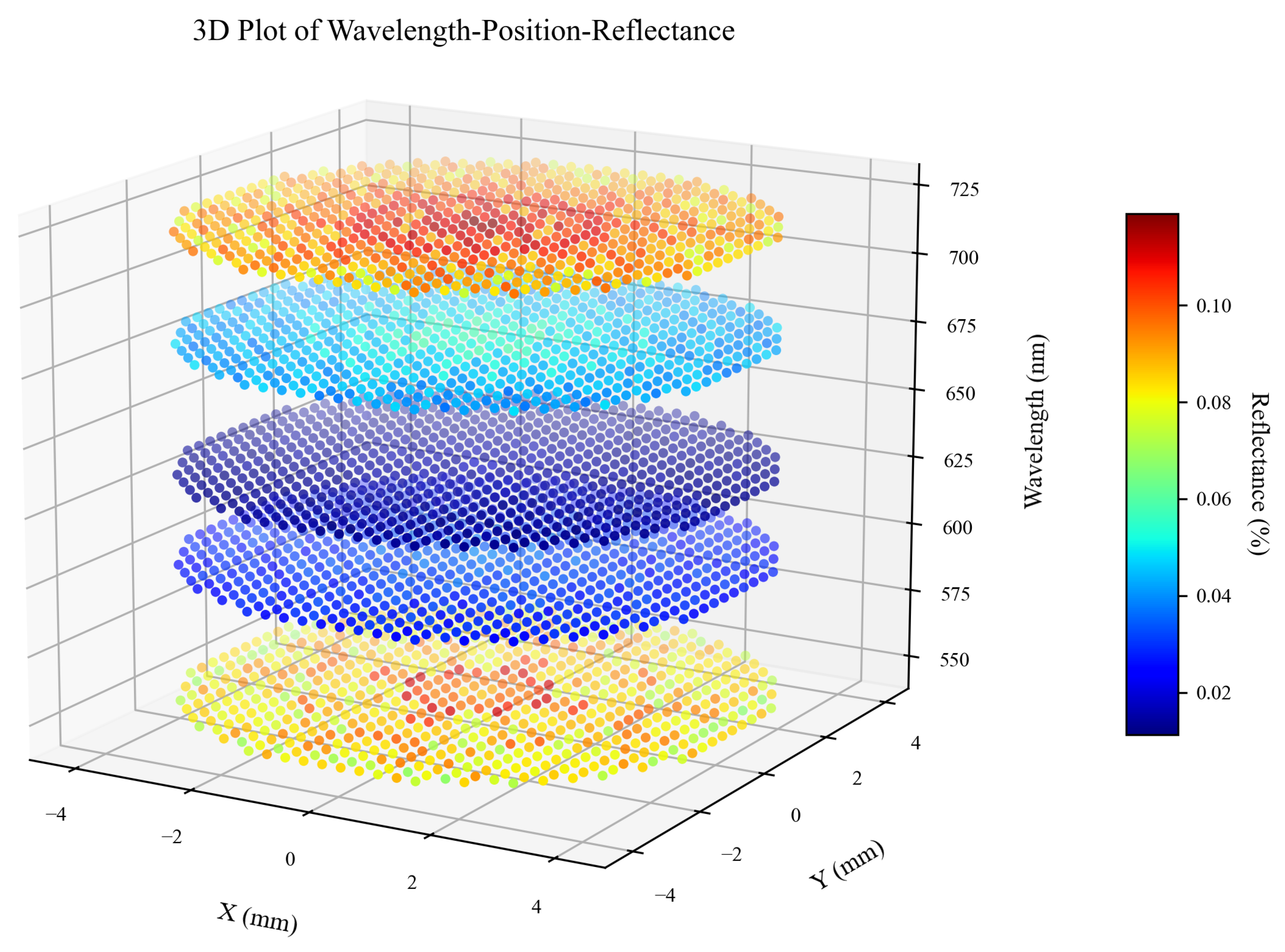
The optimized anti-reflective coating performance is shown in Figure 1, Figure 2, Figure 3 and Figure 4 and Table 7, with all core indicators meeting standards. All results are based on 25 × 25 optimization grid, 30 × 30 visualization grid, averaged over 3 repetitions. Figure 1 shows the 3D distribution of reflectance across position and wavelength (550–720 nm) within the aperture. The color scale quantifies reflectance percentages, with deep blue corresponding to low values. We can observe that the reflectance remains at a low level across the 550–720 nm band, and the spatial distribution within each wavelength layer is nearly uniform. This indicates that the Sellmeier dispersion-corrected refractive index and dual-scale moth-eye structure synergistically ensure broadband low-reflectance performance and spatial uniformity, meeting the strict requirements of high-performance optical systems.
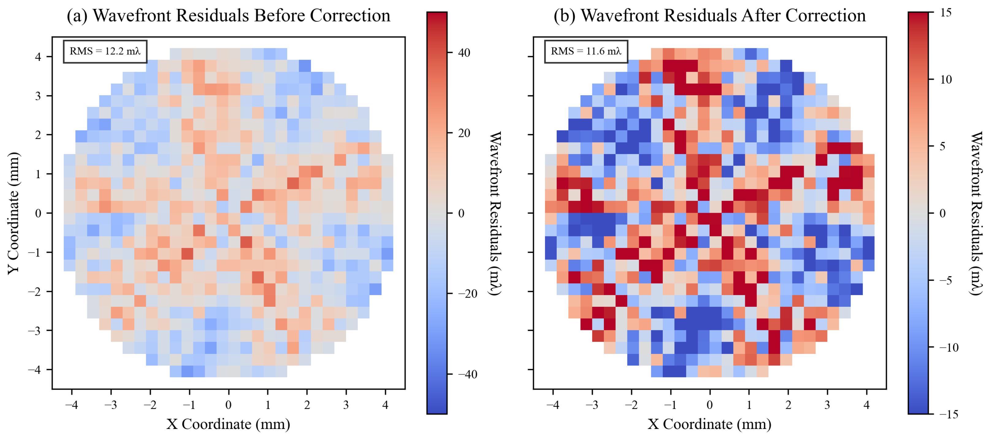
Figure 2 compares wavefront residual distributions before and after Zernike correction. Subfigure (a) shows pre-correction RMS of 12.2 m λ , dominated by low-order aberrations (tilt, defocus); subfigure (b) post-correction RMS reduced to 11.6 m λ , with significantly compressed dynamic range, correction rate of 5.1%. This result verifies the effectiveness of the Zernike-driven mechanism in alleviating phase distortions, providing a foundation for high-resolution imaging and high-power laser applications.
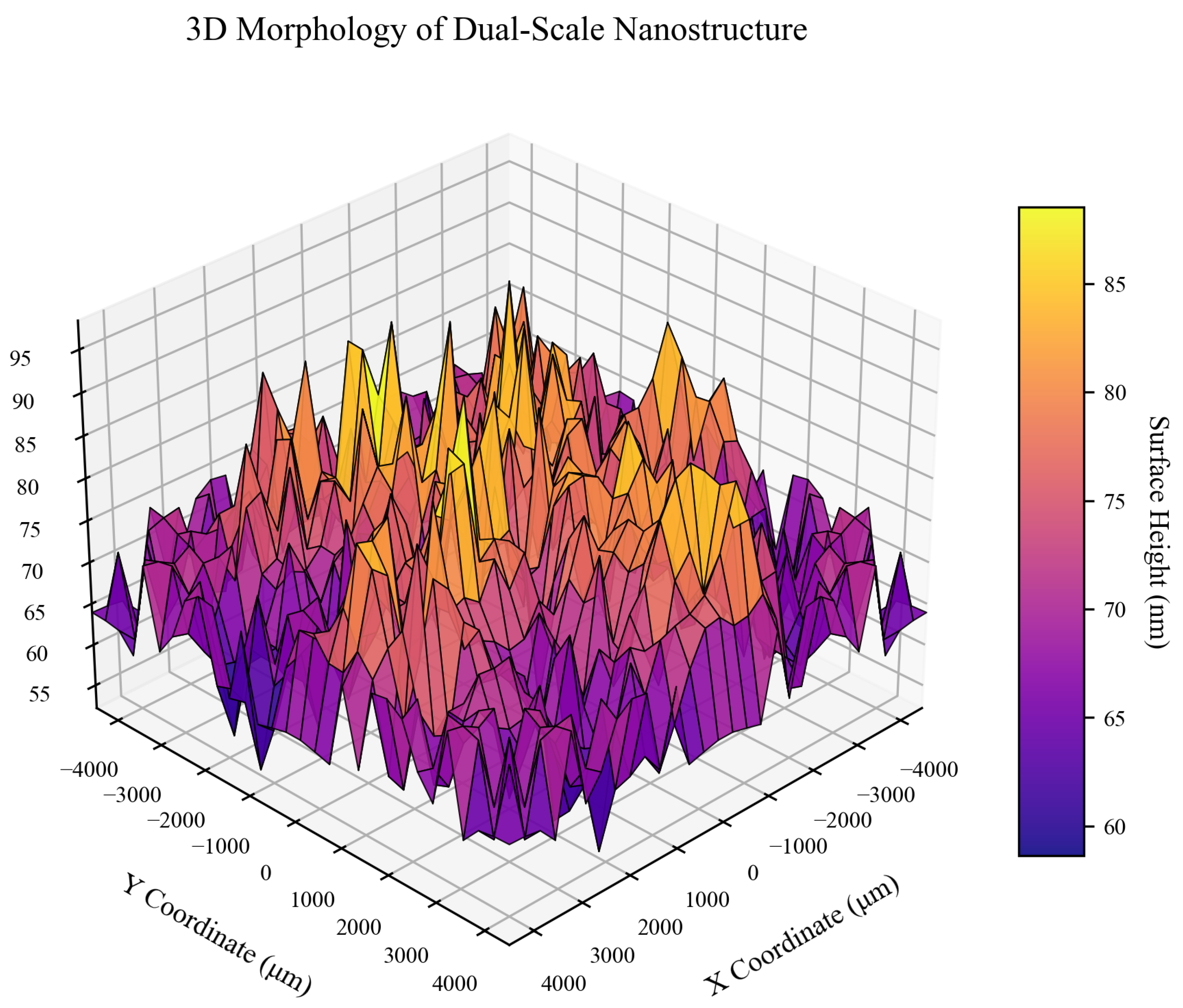
Figure 3 presents the three-dimensional morphology of the dual-scale nanostructure, showing a periodic moth-eye array, with the primary scale array forming a gradient refractive index, avoiding additional losses introduced by discrete scatterers. The secondary scale texture suppresses high-frequency reflection, ensuring surface morphology continuity. Height range 53–97 nm, standard deviation 7.7 nm, curvature proxy S RMS 0 , κ max = 0.59 m−2 far below demolding threshold. This design balances broadband anti-reflection and manufacturing smoothness, compatible with nanoimprinting processes.
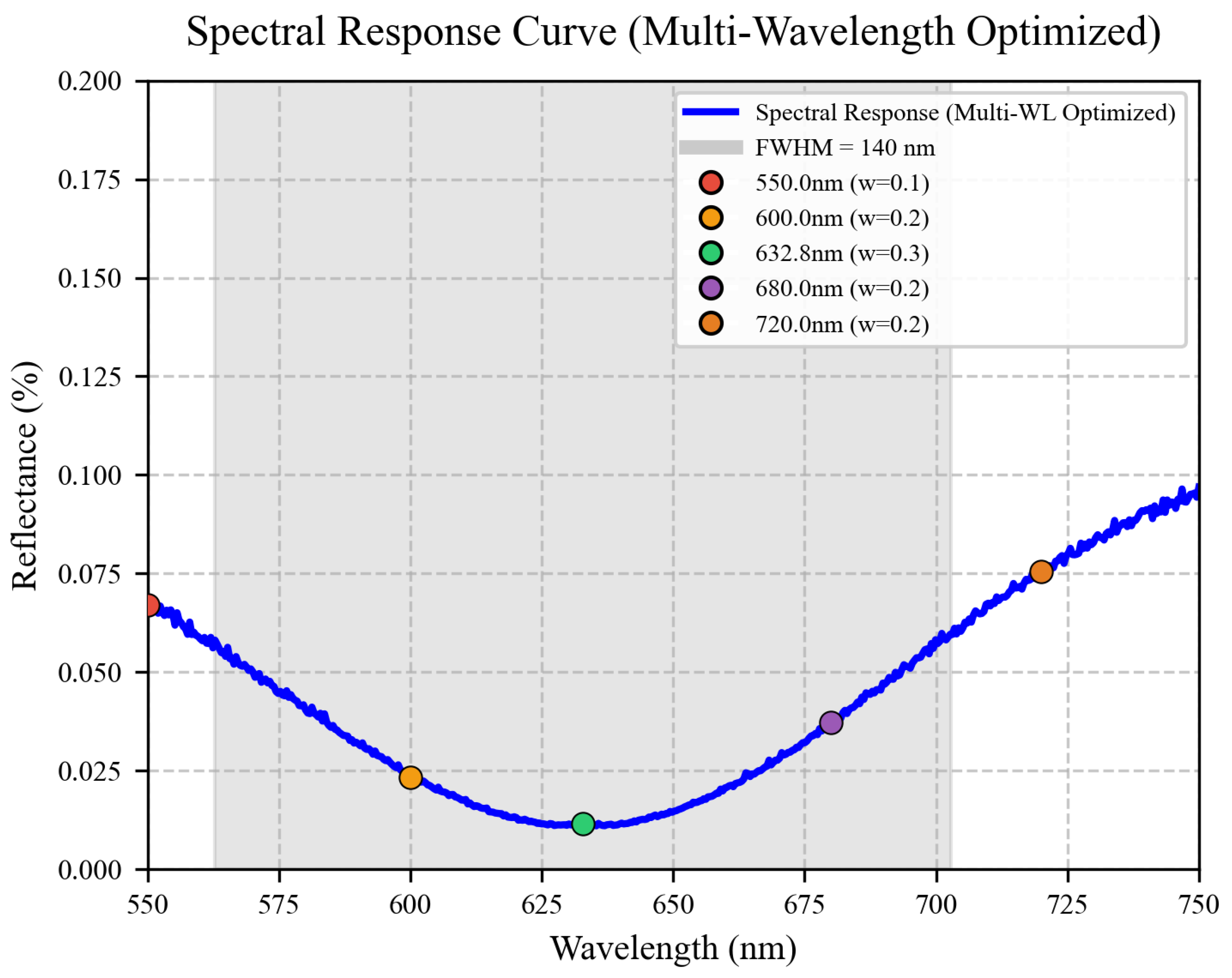
Figure 4 shows the spectral response curve (multi-wavelength optimized). We can observe that at the base design wavelength of 632.8 nm, the reflectivity reaches a valley of 0.011% (corresponding to the green dot), with a FWHM of 140 nm, covering the 550–720 nm visible range. The combination of Sellmeier dispersion correction and multi-wavelength optimization ensures ultra-low reflection at the base wavelength, while maintaining stable low reflectivity across the entire broadband range, making it suitable for high-performance broadband imaging systems and multi-wavelength laser applications.
In summary, this model achieves collaborative optimization across the three-dimensional objectives of “low reflection-high wavefront-manufacturable”, providing an efficient design paradigm for high-precision optical systems.

4. Conclusions

This study constructs a hybrid model integrating multi-layer thin films and dual-scale nanostructures, incorporating a multi-wavelength weighted optimization strategy and Sellmeier dispersion formula calculation to achieve multi-objective collaborative optimization of reflectance, wavefront quality, and surface roughness, with a systematic comparison against the traditional λ / 4 single-layer anti-reflection coating (ARC). Numerical simulation results demonstrate that the proposed method reduces the average reflectance to 0.13% and achieves a reflectance uniformity of 10.7%, realizing over 90% reflectance suppression compared to the λ / 4 ARC (average reflectance of 1.3∼1.5%).
Meanwhile, aberration correction based on Zernike polynomials significantly suppresses low-order aberrations, with the wavefront root-mean-square (RMS) error only 11.6 milliwavelengths. The surface height standard deviation is optimized to 7.7 nm, ensuring manufacturing process compatibility. Through multi-wavelength weighted optimization covering 550 nm, 600 nm, 632.8 nm, 680 nm, and 720 nm, combined with the accurate calculation of material refractive indices at different wavelengths and dispersion effect correction via the Sellmeier dispersion formula, the full width at half maximum (FWHM) of the spectrum is successfully extended to 140 nm, greatly enhancing broadband adaptability.
The core innovation of this model lies in the deep integration of multi-wavelength optimization and precise dispersion calculation, which solves the problem of excessive broadband reflectance fluctuation in traditional designs. Simultaneously, the combination of the transfer matrix method and nano-surface gradient correction technology resolves the inherent conflict between reflectance suppression and wavefront distortion, while the fast convergence of the L-BFGS-B algorithm in the six-dimensional parameter space further eliminates reliance on empirical parameters and significantly improves optimization efficiency.
Compared with the λ / 4 ARC, the proposed design achieves substantial improvements in reflectance suppression, broadband adaptability, and wavefront quality while maintaining comparable process compatibility. This framework is not only applicable to precision manufacturing processes such as ultraviolet nanoimprint lithography and electron beam evaporation but also provides an extensible solution paradigm for similar optical inverse problems.
In engineering applications, the proposed design can significantly improve the energy transmission efficiency of high-power laser devices and reduce the risk of thermal damage; in astronomical observation and semiconductor lithography systems, it can ensure diffraction-limited imaging performance and nanoscale resolution. This research promotes the evolution of optical coatings from single-performance optimization to multi-functional integration, possessing important practical promotion value.


Author Contributions

Conceptualization: L.H. and L.Z.; Methodology: H.S. and L.Z.; Software: X.W.; Validation: H.S.; Formal analysis: L.H. and L.Z.; Investigation: L.H.; Resources: L.H.; Writing—original draft preparation: H.S.; Writing—review and editing: H.S.; Visualization: X.W.; Supervision: L.Z.; Project administration: L.H.; Funding acquisition: L.H. and L.Z. All authors have read and agreed to the published version of the manuscript.

Funding

This work was supported by National Natural Science Foundation of China No. 61671404, the Open Fund of Zhejiang Key Laboratory of Film and TV Media Technology, No. 2024E10023.

Data Availability Statement

All the codes used in this paper have been openly released at https://github.com/locustzhang/Zernike-Correction-and-Multi-Objective-Optimization-of-M-Layer-Dual-Scale-Nano-Coupled-AR-Coatings (accessed on 26 January 2026).

Conflicts of Interest

The authors declare no conflicts of interest.

References

  1. ISO 10110-8; Optics and Photonics—Preparation of Drawings for Optical Elements and Systems—Part 8: Surface Texture. ISO: Geneva, Switzerland, 2019.
  2. Yoder, P.R.; Vukobratovich, D. Opto-Mechanical Systems Design, 4th ed.; CRC Press: Boca Raton, FL, USA, 2015. [Google Scholar]
  3. Doyle, K.B.; Genberg, V.L.; Michels, G.J. Integrated Optomechanical Analysis, 2nd ed.; SPIE Press: Bellingham, WA, USA, 2012. [Google Scholar]
  4. Macleod, H.A. Thin-Film Optical Filters, 5th ed.; CRC Press: Boca Raton, FL, USA, 2017. [Google Scholar]
  5. Thelen, A. Design of Optical Interference Coatings; McGraw-Hill: New York, NY, USA, 1989. [Google Scholar]
  6. Dobrowolski, J.A.; Poitras, D.; Ma, P.; Vakil, H.; Acree, M. Toward perfect antireflection coatings: Numerical investigation. Appl. Opt. 2002, 41, 3075–3083. [Google Scholar] [CrossRef] [Scilit]
  7. Clapham, P.B.; Hutley, M.C. Reduction of Lens Reflexion by the “Moth Eye” Principle. Nature 1973, 244, 281–282. [Google Scholar] [CrossRef] [Scilit]
  8. Raut, H.K.; Ganesh, V.A.; Nair, A.S.; Ramakrishna, S. Anti-reflective coatings: A critical, in-depth review. Energy Environ. Sci. 2011, 4, 3779–3804. [Google Scholar] [CrossRef] [Scilit]
  9. Wang, Y.; Lu, N.; Xu, H.; Shi, G.; Xu, M.; Lin, X.; Li, H.; Wang, W.; Qi, D.; Lu, Y.; et al. Efficient fabrication of ordered nanostructures from a single patterned virus template. Nano Res. 2010, 3, 520–527. [Google Scholar] [CrossRef] [Scilit]
  10. Chen, J.Y.; Chang, W.L.; Huang, C.K.; Sun, K.W. Biomimetic nanostructured antireflection coating and its application on crystalline silicon solar cells. Opt. Express 2011, 19, 14411–14419. [Google Scholar] [CrossRef] [Scilit]
  11. Shanmugam, N.; Pugazhendhi, R.; Elavarasan, R.M.; Kasiviswanathan, P.; Das, N. Anti-Reflective Coating Materials: A Holistic Review from PV Perspective. Energies 2020, 13, 2631. [Google Scholar] [CrossRef] [Scilit]
  12. Sood, A.K.; Pethuraja, G.; Sood, A.W.; Welser, R.E.; Puri, Y.R.; Cho, J.; Schubert, E.F.; Dhar, N.K.; Wijewarnasuriya, P.S.; Soprano, M.B. Development of Nanostructured Antireflection Coatings for EO/IR Sensor Applications. Proc. SPIE 2012, 8512, 85120D. [Google Scholar] [CrossRef]
  13. Shao, T.; Tang, F.; Sun, L.; Ye, X.; He, J.; Yang, L.; Zheng, W. Fabrication of Antireflective Nanostructures on a Transmission Grating Surface Using Nanosphere Lithography. Nanomaterials 2019, 9, 180. [Google Scholar] [CrossRef] [Scilit]
  14. Karadzhov, I.; Paulillo, B.; Rombaut, J.; Koch, K.W.; Mazumder, P.; Pruneri, V. Mechanically-Durable Antireflective Subwavelength Nanoholes on Glass Surfaces Using Lithography-Free Fabrication. ACS Appl. Mater. Interfaces 2024, 16, 19672–19682. [Google Scholar] [CrossRef] [Scilit]
  15. Li, Z.; Song, C.; Li, Q.; Xiang, X.; Yang, H.; Wang, X.; Gao, J. Hybrid Nanostructured Antireflection Coating by Self-Assembled Nanospheres for Crystalline Silicon Solar Cells. Coatings 2019, 9, 453. [Google Scholar]
  16. Nosidlak, N.; Jaglarz, J.; Vallati, A.; Dulian, P.; Jurzecka-Szymacha, M.; Gierałtowska, S.; Seweryn, A.; Wachnicki, ł.; Witkowski, B.S.; Godlewski, M. The Optical Properties of Thin Film Alloys of ZnO, TiO2 and ZrO2 with Al2O3 Synthesised Using Atomic Layer Deposition. Coatings 2023, 13, 1872. [Google Scholar] [CrossRef] [Scilit]
  17. Schubert, M.F.; Mont, F.W.; Chhajed, S.; Poxson, D.J.; Kim, J.K.; Schubert, E.F. Design of multilayer antireflection coatings made from co-sputtered and low-refractive-index materials by genetic algorithm. Opt. Express 2008, 16, 5290–5298. [Google Scholar] [CrossRef] [Scilit] [PubMed]
  18. Schneider, P.I.; Santiago, X.G.; Soltwisch, V.; Hammerschmidt, M.; Burger, S.; Rockstuhl, C. Benchmarking Five Global Optimization Approaches for Nano-Optical Shape Optimization and Parameter Reconstruction. ACS Photonics 2019, 6, 2726–2733. [Google Scholar] [CrossRef] [Scilit]
  19. Tran, V.T.; Mai, H.V.; Nguyen, H.M.; Duong, D.C.; Vu, V.H.; Hoang, N.N.; Nguyen, M.V.; Mai, T.A.; Tong, H.D.; Nguyen, H.Q.; et al. Optimization of antireflective graded structure for infrared applications. Appl. Opt. 2022, 61, 3328–3337. [Google Scholar] [CrossRef] [Scilit]
  20. Ma, T.; Ma, M.; Guo, L.J. Optical Multilayer Thin Film Structure Inverse Design: From Optimization to Deep Learning. iScience 2025, 28, 112222. [Google Scholar] [CrossRef] [Scilit]
  21. Guo, X.; Lu, J.; Li, Y.; Li, J.; Huang, W. Inverse Design for Coating Parameters in Nano-Film Growth Based on Deep Learning Neural Network and Particle Swarm Optimization Algorithm. Photonics 2022, 9, 513. [Google Scholar] [CrossRef] [Scilit]
  22. Sikder, U.; Zaman, M.A. Optimization of multilayer antireflection coating for photovoltaic applications. Opt. Laser Technol. 2016, 79, 88–94. [Google Scholar] [CrossRef] [Scilit]
  23. Choi, C.S.; Lee, S.; Lim, M.S.; Choi, K.C.; Kim, D.; Jeon, D.Y.; Yang, Y.; Park, O.O. Improved light extraction efficiency in organic light emitting diodes with a perforated WO3 hole injection layer fabricated by use of colloidal lithography. Opt. Express 2012, 20, 12345–12352. [Google Scholar] [CrossRef] [Scilit]
  24. Du, W.; Yin, G.; Ma, Y.G. High-performance near-field thermophotovoltaic device with CaF2/W multilayer hyperbolic metamaterial emitter. Acta Phys. Sin. 2020, 69, 204203. [Google Scholar] [CrossRef] [Scilit]
  25. Hedayati, M.K.; Elbahri, M. Antireflective Coatings: Conventional Stacking Layers and Ultrathin Plasmonic Metasurfaces, A Mini-Review. Materials 2016, 9, 497. [Google Scholar] [CrossRef] [Scilit]
  26. Zhu, Y.; Zhao, Y.; Holtz, M.; Fan, Z.; Bernussi, A.A. Effect of substrate orientation on terahertz optical transmission through VO2 thin films and application to functional antireflection coatings. J. Opt. Soc. Am. B 2012, 29, 2373–2378. [Google Scholar] [CrossRef] [Scilit]
  27. Polyanskiy, M.N. RefractiveIndex. INFO Database. Available online: https://refractiveindex.info (accessed on 23 January 2026).
  28. Mohammed, Z.H. The Fresnel coefficient of thin film multilayer using transfer matrix method TMM. IOP Conf. Ser. Mater. Sci. Eng. 2019, 518, 032026. [Google Scholar] [CrossRef] [Scilit]
  29. Morozov, G.V. Two forms of transfer matrix for one-dimensional optical structures. Opt. Quantum Electron. 2023, 55, 1120. [Google Scholar] [CrossRef] [Scilit]
Figure 1. Distribution of Reflectance Across Position and Wavelength.
Modelling 07 00029 g001
Figure 2. Wavefront Residuals Before and After Zernike Correction.
Modelling 07 00029 g002
Figure 3. Optimized Dual-Scale Nanostructure Three-Dimensional Morphology.
Modelling 07 00029 g003
Figure 4. Multi-Wavelength Optimized Spectral Reflectance Curve of the Anti-Reflective Coating.
Modelling 07 00029 g004
Table 1. Main Symbol Explanations.
SymbolExplanation
n i Refractive index of the i-th layer coating (dimensionless), i = 1 , 2 , , N , N = 5 for the number of layers
d i Physical thickness of the i-th layer coating (m)
Q i Optical thickness of the i-th layer (quarter-wavelength units), Q i = 4 n i d i / λ
ω i Weighting factor for the i-th discrete wavelength (dimensionless), i = 1 , 2 , , 5 (covers the target broadband), satisfying i = 1 5 ω i = 1
λ i The i-th discrete wavelength in the target broadband (unit: nm), i = 1 , 2 , , 5 , covering the visible to near-infrared spectral range of 550–720 nm
θ Incidence angle (rad)
R ( λ i , θ ) Reflectivity of the coating at wavelength λ i and incidence angle θ (dimensionless)
W RMS Wavefront root mean square error (wavelength units), measuring optical wave distortion
S RMS Surface roughness root mean square error (m), proxy for manufacturing flatness
h 0 Peak height of nanostructure (m)
p = [ h 0 , p 1 , p 2 , p 3 , p 4 , p 5 ] Optimization parameter vector, p j are Zernike polynomial coefficients (dimensionless)
Z ( x , y ) Nano-surface height function (m), x , y are transverse coordinates (m)
F opt ( p ) Optimization objective function (dimensionless), integrating multi-objective losses
α , β , γ Objective function weights (dimensionless), corresponding to reflectivity, wavefront quality, and surface roughness respectively
ρ , ϑ Polar coordinates, ρ = x 2 + y 2 / r ap (normalized radius), ϑ = arctan ( y / x ) (angle)
r ap Aperture radius (m)
Table 2. Dual-Scale Modulation Factors (m2 for Primary Scale, m2 for Secondary Scale).
TypeExpressionSignificance
Primary m 1 0.85 + 0.15 sin 2 ( 2 π ρ · 6.5 ) sin ( 4.5 ϑ ) Macroscopic moth-eye modulation
Secondary m 2 0.92 + 0.08 sin 2 π r 0.12 λ Nanoscale texture
Notes: ρ and ϑ are radial and angular coordinates; r = x 2 + y 2 ; period 0.12 λ i .
Table 3. Zernike Polynomial Correction Term j = 1 5 p j Z j .
Index jAberration TypeExpression
1X-direction tilt (tilt x) Z 1 = 2 ρ cos ϑ  
2Y-direction tilt (tilt y) Z 2 = 2 ρ sin ϑ  
3Defocus Z 3 = 3 ( 2 ρ 2 1 )  
4Astigmatism (astig) Z 4 = 6 ρ 2 cos ( 2 ϑ )  
5Coma Z 5 = 8 ( 3 ρ 3 2 ρ ) cos ϑ
Table 4. Optimization Hyperparameters and Boundary Constraints.
ParameterValueBasis
Optimization variables p [ h 0 , p 1 , p 2 , p 3 , p 4 , p 5 ] Nano peak height and Zernike correction coefficients
h 0 boundary [ 0.16 λ , 0.17 λ ] Approximately 100–108 nm, meeting subwavelength structure requirements
| p j | upper limit 0.02 Small perturbation assumption, avoiding disruption of surface continuity
Weights ( α , β , γ , δ ) ( 70 , 20 , 7 , 3 ) Prioritizing ultra-low reflection, followed by wavefront quality and manufacturing smoothness
ω i (0.1, 0.2, 0.3, 0.2, 0.2)prioritizes the central wavelength (632.8 nm) with weights, balancing broadband performance
Reflection loss coefficients ( c 1 , c 2 ) ( 15 , 3 ) Magnitude matching and center uniformity enhancement
Spectral broadening coefficient a 1 0.0017Empirical constants
Subwavelength modulation coefficients ( m 1 , m 2 , m 3 ) ( 0.88 , 0.12 , 3.5 ) Empirical constants
Radial optimization coefficients ( n 1 , n 2 ) ( 0.75 , 0.25 ) Empirical constants
Zernike correction strength ϵ 0.015 Controls the amplitude of low-order aberration introduction
Subwavelength period p sub 150 nmMeets effective medium approximation (EMA) across 550–720 nm, compatible with UV nanoimprinting
Design wavelength λ i (550, 600, 632.8, 680, 720) nmrepresentative wavelengths for 550–720 nm broadband optimization
Table 5. The V-H-V-H-V anti-reflective coating.
Layer No.MaterialnQ (Quarter-Wavelength Units)
1SiO2 (ULD)1.420.81
2HfO22.050.56
3SiO21.460.67
4Ta2O52.100.61
5MgF21.380.54
Table 6. Basic Simulation Parameters.
ParameterValue
Aperture diameter 2 r ap 9.0 mm
Optimization grid resolution 25 × 25
Visualization grid resolution 30 × 30
Maximum iterations200
Theoretical multi-layer reflectivity R0.01–0.2%
Surface curvature threshold κ th 1.2 × 10 7 m−2
Table 7. Performance Comparison of the Novel Coating with Single-Layer λ /4 ARC and Industry Standards.
Performance IndicatorProposed Multi-Wavelength Nano-Coupled ARCBenchmark λ /4 Single-Layer ARCHigh-Precision Industry StandardCompliance
Valley Reflectivity (632.8 nm)0.011%1.46%<0.10%Meets
Weighted Average of Valley Reflectance0.037%1.51%--
Reflectance Uniformity10.3%2.27%<15.0%Meets
Post-Correction Wavefront RMS11.6 m λ -<12.0 m λ Meets
Height Standard Deviation7.7 nm-<12.0 nmMeets
FWHM of Reflectance Valley140 nm85 nm>100 nmMeets
Maximum Curvature ( κ m a x )0.59 m−22.1 m−2< 1.2 × 10 5 m 2 Meets
Disclaimer/Publisher’s Note: The statements, opinions and data contained in all publications are solely those of the individual author(s) and contributor(s) and not of MDPI and/or the editor(s). MDPI and/or the editor(s) disclaim responsibility for any injury to people or property resulting from any ideas, methods, instructions or products referred to in the content.