Article

Equivalent Stress Model-Assisted Aero-Structural Optimization of a Compressor Rotor Using an Adjoint Method

1
School of Aeronautics and Astronautics, Zhejiang University, Hangzhou 310027, China
2
Windey Energy Technology Group Co., Ltd., Hangzhou 310012, China
*
Author to whom correspondence should be addressed.
Modelling 2025, 6(4), 125; https://doi.org/10.3390/modelling6040125
Submission received: 5 August 2025 / Revised: 19 September 2025 / Accepted: 9 October 2025 / Published: 11 October 2025

Abstract

To meet the stringent reliability requirements of rotor blades in turbomachines, greater effort should be devoted to improving both aerodynamic and structural performance in blade design. This paper introduces an aero-structural multi-disciplinary design optimization (MDO) method for compressor rotor blades using a discrete adjoint method and an equivalent stress model (ESM). The principles of the ESM are firstly introduced, and its accuracy in calculating equivalent stress is validated through comparison with a commercial program. Both the aerodynamic performance and the maximum equivalent stress (MES) are selected as optimization objectives. To modify the blade profile, the steepest descent optimization method is utilized, in which the necessary sensitivities of the cost function to the design parameters are calculated by solving the adjoint equations. Finally, the aero-structural MDO of a transonic compressor rotor, NASA Rotor 67, is conducted, and the Pareto solutions are obtained. The optimization results demonstrate that the adiabatic efficiency and the MES are competitive in improving multi-disciplinary performance. For most of the Pareto solutions, the MES can be considerably reduced with increased adiabatic efficiency.

1. Introduction

The rotor blade is an important component of the aero-engine that performs the essential function of energy conversion. It directly affects the fuel consumption rate and overall economic performance of an aircraft. In addition, the rotor blade is subjected to various loads when in operation. If its strength is insufficient, failures such as cracks or breakages may occur. Therefore, it is necessary to perform aero-structural multi-disciplinary design optimization (MDO) in blade design to enhance the blade’s structural strength and aerodynamic performance while ensuring its reliable operation [1].
In aero-structural MDO, a number of gradient-free optimization methods, including surrogate models and evolutionary algorithms, have been widely used in both the industrial and academic communities. Parameters determining the blade geometry, such as the sweep, stagger angle, and profile, are treated as design parameters. The coupled governing flow equations and structure equation are solved concurrently [2]. Lian and Liou [3] used a response surface model and genetic algorithm in the aero-structural MDO of a transonic rotor blade. In their study, thin-shell approximation was employed in finite element analysis to reduce the computational cost. Sivashanmugam et al. [4] performed the aero-structural MDO of a turbine blade to improve the efficiency and von Mises stress using a multi-objective genetic algorithm assisted by response surface approximation. Luo et al. [5] established a multi-disciplinary optimization framework based on a data-driven multi-objective evolution algorithm. This gradient-free method is simple and easily implemented, but the computational cost is strictly dependent on the number of design parameters. When the number of design parameters is large, the demand for computational resources is considerable high.
In the gradient-based aero-structural MDO of turbomachinery blades, the direct method and adjoint method [6,7,8] are often used. The sensitivity calculation time in the direct method is linearly dependent on the number of design parameters. In contrast, the computational cost of first-order sensitivity calculation using the adjoint method is almost independent of the number of design parameters, making the adjoint method suitable for refined optimization with multiple design parameters [9]. However, the adjoint-based aero-structural MDO requires the derivations of the adjoint equations corresponding to both the governing flow equations and the structure equation. The adjoint variables in two different disciplines need to be transferred to the fluid–structure interface, making the development of the MDO adjoint solver more challenging. At present, there has been some progress in adjoint-based MDO with external flow. Martins et al. [10,11] first applied the adjoint method to a stable coupled aero-structural system for the multi-disciplinary optimization of an aircraft wing. After some time, Meryem et al. [12] also achieved aero-structural optimization based on coupled adjoint sensitivity analysis. Lei [13] developed a high-fidelity aero-structural sensitivity calculation method based on the adjoint method and performed aero-structural adjoint-based design optimization for wing planform geometry and the positions of the front and rear spars, achieving a 16.8% increase in wing stiffness and a 2.4% reduction in drag.
For turbomachinery blades, the application of the adjoint method to aero-structural multi-disciplinary optimization is limited. Using the adjoint method, He and Wang [14] achieved the aerodynamic-aero-elastic optimization of a single row by introducing the harmonic balance method into unsteady flow computation. Wu et al. [15] performed the optimization of compressor blades using a fully turbulent adjoint harmonic balance method to minimize the forced response. Taking the stress into account, Mueller et al. [16] proposed a multi-disciplinary and multi-point adjoint-based optimization procedure and successfully improved the total-to-static efficiency of the turbine, while the mechanical stresses were maintained below critical values. Cuciumita et al. [17] carried out the optimization of a high-loading compressor blade to improve aerodynamic performance with structural constraint, in which aerodynamic sensitivity calculation relies on the discrete adjoint method, while those of structural parameters were calculated using the finite difference method (FDM). Yang et al. [18] proposed an efficient finite element stress sensitivity analysis method based on the adjoint method using CalculiX but did not consider aerodynamic performance in their study.
Computational costs should be considered in aero-structural optimization, because the process repeatedly relies on flow simulation based on computational fluid dynamics (CFD) and structural analysis based on computational structural mechanics (CSM). Although the aerodynamic-adjoint equations and the structural-adjoint equation are decoupled in the open report [16], it is necessary to solve additional structural-related differential equations through comparison with adjoint-based aerodynamic design optimization, resulting in higher computational costs. Cuciumita et al. [17] did not solve the structural-adjoint equation in their study, but extensive CSM was necessary to construct a response surface model to predict mechanical stress. However, their work provided another method for calculating structural sensitivities in adjoint-based aero-structural optimization.
To further reduce the computational cost of adjoint-based aero-structural optimization and simplify the MDO problem, this paper firstly introduces an equivalent stress model (ESM) to predict mechanical stress. The bending moment caused by the aerodynamic loads and centrifugal force and the equivalent stress are computed using the proposed ESM, the accuracy of which is validated through comparison with a commercial program. Then, the flow simulation method, discrete adjoint method, and optimization method are introduced. In the aero-structural optimization of the transonic compressor rotor blade, NASA Rotor 67 [19], the maximum equivalent stress (MES) and the entropy production are regarded as the objectives, and their sensitivities are calculated using FDM and the adjoint method, respectively. The optimization results and analysis are presented in detail.

2. Equivalent Stress Model

2.1. Introduction to ESM

The purpose of employing an equivalent stress model in aero-structural MDO is to swiftly calculate the stress independently of solving the structural equations. The most critical aspect of the proposed ESM is the initial calculation of the accumulated moment, through which the stress at a specified point can then be determined. We will now present calculations of the bending stress and tensile stress resulting from the aerodynamic loads and centrifugal force.
Bending Stress. The rotor blade experiences aerodynamic loads during operation, with the pressure side being greater than the suction side. The bending moment resulting from the aerodynamic load at the blade root (hub) has significant impacts on the stress distribution and the structural strength of the blade. For any surface element on the rotor blade, the pressure imposed on it can be described by pdA, with p and dA representing the area of the surface element and the static pressure, respectively. Thus, the aerodynamic bending moment of the rotor blade can be determined as follows:
M a e r o = ( r × n ) p d A
where n is the outward normal direction of the surface element, and r is the position vector of the surface element starting from the root as shown in Figure 1a. In the figure, LE and TE represent the leading edge and the trailing edge of the blade, respectively.
Additionally, the rotor blade in operation experiences centrifugal force. This centrifugal force is regarded as the main cause of blade deformation and structural stresses. As shown in Figure 1b, for a volumetric element dV within the blade, its mass is d m = ρ d V and the position vector from the rotation axis is R . The centrifugal force imposed on the element is Ω 2 R d m with Ω representing the rotation speed. The centrifugal force can be further decomposed into two components, one parallel to the centrifugal mass distribution axis of the blade and the other perpendicular to the axis. The former results in tensile stress, and the latter results in the bending moment at the blade root. Reducing the bending moment can significantly reduce the maximum structural stress. The centrifugal bending moment can be calculated through the following steps:
Step 1: Neutral axis–root intersection
Calculate the intersection point of the blade root and the neutral axis. For the rotor blade, the neutral axis intersects the blade root at the centroid.
Step 2: Centrifugal force calculation
Calculate the centrifugal force G imposed on all elements.
Step 3: Distance from centroid to root
Calculate the straight-line distance r from the centroid of each volume element to the centroid of the blade root.
Step 4: Centrifugal bending moment calculation
Calculate the centrifugal force-induced bending moment M g r a v = r × G .
The total bending moment imposed on the blade root, referred to as the resultant bending moment, is the sum of the aerodynamic bending moment and the centrifugal bending moment:
M = M a e r o + M g r a v
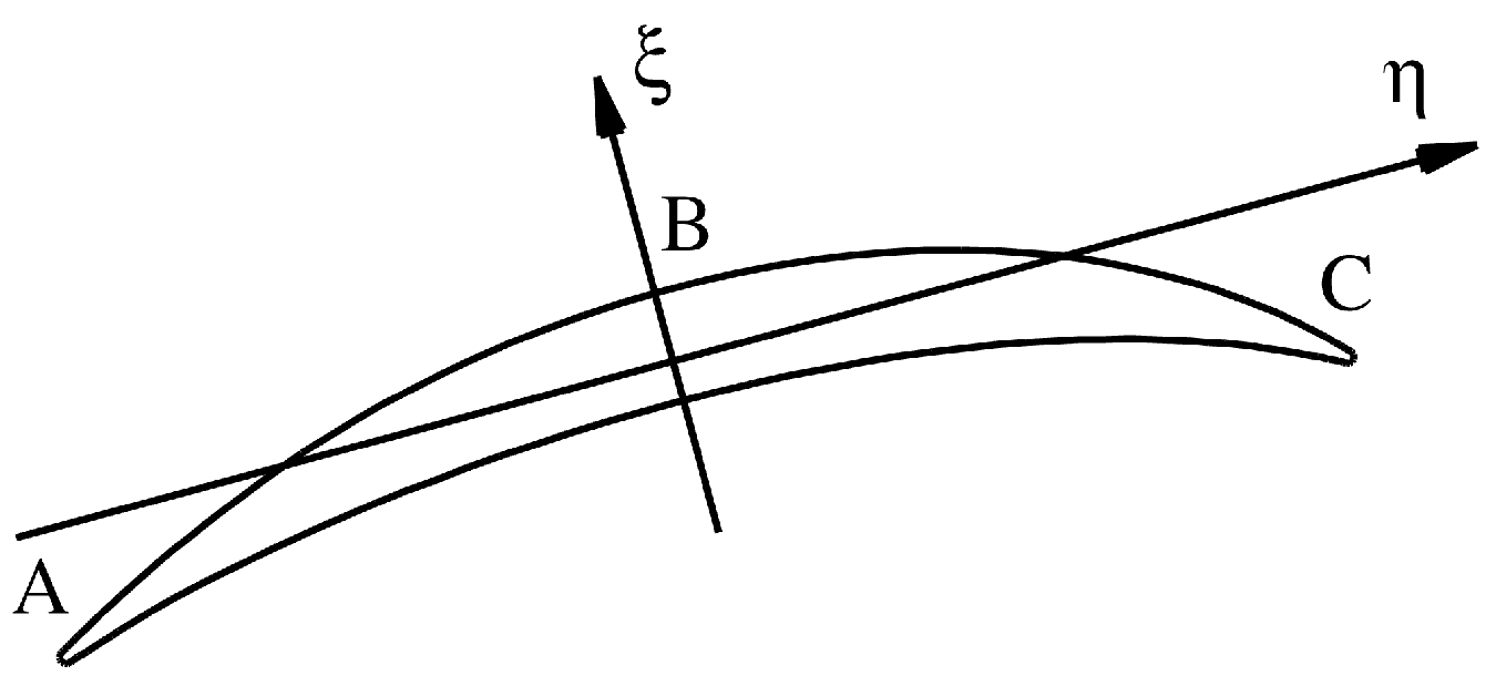
The resultant bending moment is calculated in the Cartesian coordinate system. However, the three axes in the Cartesian coordinate system are usually not the principal axes of inertia of the blade. After calculating the resultant bending moment on the blade root, it is necessary to calculate the principal axes of inertia and the corresponding principal moment. Moreover, because the blade profile at the root is usually not changed in the design, the principal axes of inertia and the principal moment of the blade root need to be calculated only once. Figure 2 shows the schematic diagram of the principal axes of inertia for an arbitrary blade section, where the principal axes pass through the centroid of the section.
Usually, the bending stress reaches its maximum at the points A, B, and C. Points A and C are the LE and TE of the blade, respectively, while point B is the one on the suction side with maximum curvature. Taking point A as an example, the bending stress can be calculated as follows:
σ b e n d , A = M ξ J ξ η A + M η J η ξ A
where M ξ and M η are the principal moment in the ξ and η direction, respectively, η A and ξ A are the local coordinates of point A relative to the principal axes of inertia, and J ξ and J η are the principal moments of inertia.
Tensile Stress. As mentioned above, the component of centrifugal force parallel to the centrifugal mass distribution axis of the blade results in tensile stress. The proposed ESM approximates the centrifugal tensile stress on the blade root as the ratio of the centrifugal force component perpendicular to the section to the area of the section. Specifically, we have
σ i = n = 1 N F n S i
where σ i is the centrifugal tensile stress on the i-th section, N is the number of elements in the section, F n is the centrifugal force perpendicular to the section induced by the n-th element, and S i is the area of the section.
Thus, the total stress at point A is the algebraic sum of the centrifugal tensile stress and the bending stress:
σ A = σ b e n d , A + σ i
where σ b e n d , A is the bending stress at point A, and σ i is the tensile stress on the i-th section.
It should be pointed out that the total stress at other points on the i-th section can be calculated using the proposed ESM. Then, the maximum stress can be acquired and used as the MES in the following optimization study.

2.2. Validation of the ESM

To validate the effectiveness of the proposed ESM, a number of rotor blades are produced through blade sweeping. The parameterization method of sweeping used in previous work [20,21] is employed in the study. Although the aerodynamic shape of the compressor rotor blade is optimized in this study, blade sweeping is more effective in generating large-scale geometric variations, thereby providing more extreme conditions for evaluating the accuracy of the ESM. The transonic rotor blade NASA Rotor 67 [19] is selected as the objective because it was designed in the last century and has been widely investigated. The specifications of this rotor blade are given in Table 1.
The parameterization of blade sweeping can be achieved by uniformly distributing a series of control points in the spanwise direction. On each of the corresponding spans, the blade profile is moved either upstream or downstream along the real chord direction, resulting in a forward-swept blade or backward-swept blade, respectively. More details can be found in Refs. [20,21]. Figure 3 shows the profiles in the meridional plane of six different sweeping blades used for validation; the profiles in black and in red are those of the original and sweeping blades, respectively. For example, the first sweeping blade is a typical backward-sweeping blade, and the fourth is a typical forward-swept blade.
In this study, the commercial program Ansys Workbench is used for the validation of the ESM. The bending moments of the original and the six sweeping blades are calculated using both the commercial program and the ESM. It is worth mentioning that the aerodynamic loads are obtained under operational conditions of near peak efficiency (PE) for Rotor 67. The results are shown in Figure 4, where the results marked as Ref and ESM are those obtained using the commercial program and the ESM, respectively. The results of these two methods are close, indicating that the ESM can accurately calculate the bending moment. Even considering the large-scale geometric deformation induced by blade sweeping, the bending moment predicted by the ESM is still a close match for that obtained using the commercial program.
For the purpose of further validation, the maximum stress of the seven blades is calculated and compared. Since the commercial program uses the maximum von Mises stress as the maximum stress, it is not strictly consistent with the MES defined in this study. Rather than comparing the absolute maximum stress, the average percentage deviation in the maximum stress is calculated as follows:
ε n = σ n σ 0 i = 1 7 ( σ i σ 0 )
where ε n denotes the stress deviation of the n-th blade, and σ 0 denotes the average maximum stress. It is worth emphasizing again that σ n represents the maximum von Mises stress when using the commercial program, while it is the MES when using the proposed ESM. Figure 5 gives the average percentage deviations for both the commercial program and the ESM. The results demonstrate that the ESM can accurately predict the qualitative variations in the maximum stress for different blades.

3. Methodology

3.1. Flow Simulation Method

The numerical simulation of the flow field of the rotor blade is achieved using an in-house flow solver [22,23], which solves the Reynolds-averaged Navier–Stokes (RANS) equations and the Spalart–Allmaras [24] turbulence model equation. Spatial discretization is achieved using the JST Scheme [25]. The Runge–Kutta time stepping and multi-grid techniques are employed to obtain the steady-state flow solutions. The flow conditions at the inlet of Rotor 67 are those given in Table 1. The inlet flow angle is zero. At the outlet, the back pressure is given on the hub and the radial equilibrium equation is solved to obtained the pressure distribution in the spanwise direction.
To ensure the reliability of the flow solutions, a grid convergence study is firstly performed. Four progressively refined single-block H-type grids with varying resolutions are used for convergence analysis. The topology of the grid is given in Figure 6. It should be mentioned that the flow computations for Rotor 67 are performed under operation condition near PE, which is also the one in the following optimization study.
The total pressure ratio π and mass flow rate M a s s of the four grids are illustrated in Figure 7. The total pressure ratio is calculated as π = p 0 , 2 / p 0 , 1 , with p 0 , 2 and p 0 , 1 representing the total pressure at the outlet and inlet, respectively. Note that both π and M a s s are normalized using the corresponding values of the fourth grid (the finest grid). Based on the convergence analysis, the third grid is selected, and the numbers of grid points in the streamwise, circumferential, and spanwise directions are 121, 65, and 65, respectively.
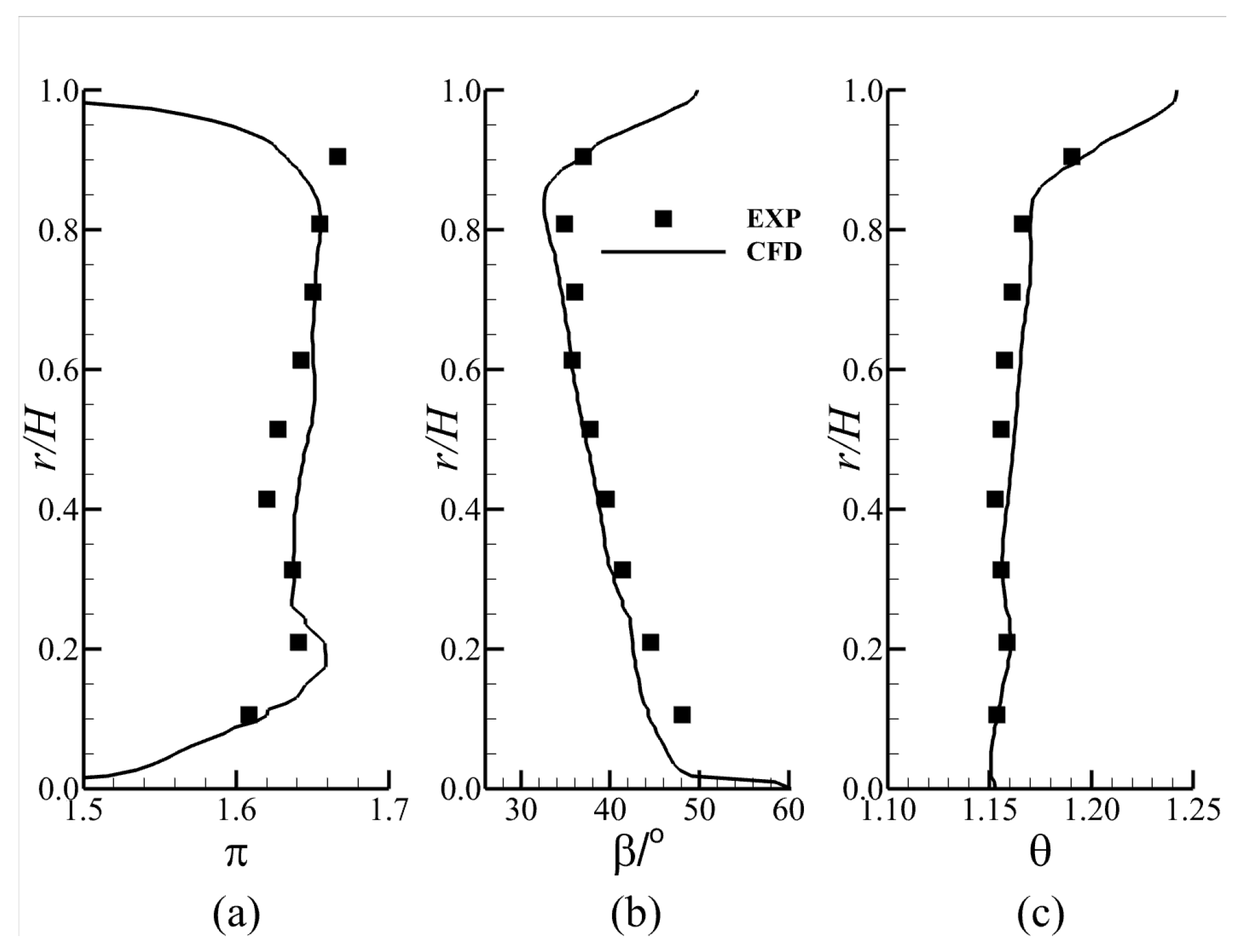
The spanwise distributions of π , the flow turning angle at the outlet β , and the total temperature ratio θ near PE are given in Figure 8. Generally, the numerical solutions show satisfactory agreement with the experimental results.

3.2. Adjoint Method

In this study, design optimization is conducted using a gradient-based method. The gradients of aerodynamic performance parameters, i.e., the sensitivities, are calculated using a fully turbulence adjoint method. The principles of the turbulence adjoint method and the implementations of the sensitivity calculation are conceptually elucidated in this study. Further details can be found in Refs. [9,26].
The cost function I, i.e., the optimization objective, is defined as a function of the blade profile depending on design parameters α and flow solutions w :
I = I ( α , w )
Moreover, the governing flow equations are given as follows:
R = R ( α , w )
In gradient-based optimization, the sensitivities of the cost function to the design parameters should be evaluated by linearizing Equation (7):
d I d α = I α + I w w α
In Equation (9), the influence of design parameters on flow solutions is included, resulting in repeated flow computations and a high computational cost. Therefore, Equation (8) is introduced as a constraint into the cost function. By linearizing Equation (8), we have
d R d α = R α + R w w α
Multiplying Equation (10) by the adjoint variables Ψ and then subtracting the product from Equation (9), we have
d I d α = I α + I w Ψ T R w w α Ψ T R α
To eliminate the effects of design parameters on flow solutions, the coefficient before w / α is set to zero as follows:
I w T R w T Ψ = 0
which is the adjoint equation corresponding to the governing flow equations, Equation (8). Then, the sensitivity of the cost function is as follows:
d I d α = I α Ψ T R α
Using the adjoint method, the governing flow equations and the adjoint equations only need to be calculated once within one optimization step, and all the sensitivities can then be obtained. The computational cost is almost independent of the number of design parameters. Moreover, Equation (13) can be further described as follows:
d I d α = I x x α Ψ T R x x α
where x represents the coordinates of the computation mesh for the flow solver. The relationship between x and α can be determined using the parameterization method.
The present authors developed a program for solving the discrete adjoint equations using automatic differentiation tool Tapenade [27], which was then used in the studies on aerodynamic design optimization of turbomachinery blades [9,26]. The program is also used in this study to solve the adjoint equations and calculate the sensitivities.

3.3. Parameterization and Optimization Methods

Be different from the parameterization method used for validation of the proposed ESM, in the design optimization, the aerodynamic shape of the rotor blade is modified. The Hicks–Henne shape functions [28] are superimposed on both the pressure and suction sides to modify the blade profile. The Hicks–Henne shape functions are given as follows:
p i ( x ) = sin 4 π x m i , m i = ln ( 0.5 ) ln ( x 0 , i ) , i = 2 , , N s 1
where p i ( x ) denotes the geometric variations that result from the i-th shape function and x 0 , i is the corresponding control point; N s is the number of shape functions. It should be noted that the control points of the above shape functions are not at LE and TE. Instead, another two shape functions with control points at LE and TE are defined as follows:
p 1 ( x ) = cos 4 π x 2 , p N s ( x ) = sin 4 π x 2
The total variation in aerodynamic shape can be determined through a weighted linear summation form of all the geometric variations:
p t ( x ) = i = 1 N s α i p i ( x )
where α i is the weight of the i-th shape function, which is regarded as the design parameter in the optimization.
Once the gradients of optimization objectives to design parameters are determined, the simple and widely used steepest descent method is used to search for the optimal solution.
α n + 1 = α n l · G
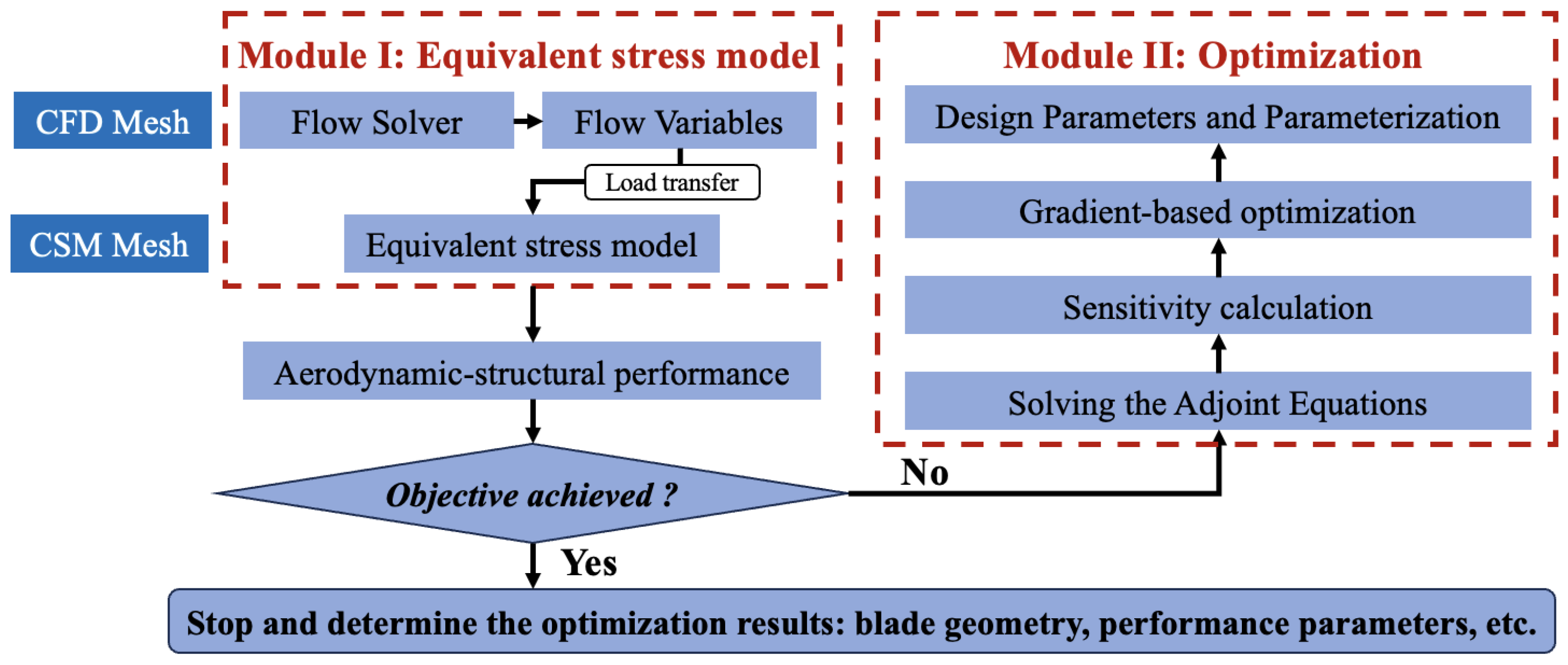
where l is the length for modifying the blade profile, and G is the vector of the gradient, i.e., the first-order sensitivities; the superscripts n and n + 1 represent the adjacent optimization steps. The procedure of the aero-structural MDO using the gradient-based method is shown in Figure 9. It should be pointed that the CSM Mesh as shown in the figure, is used for calculating the equivalent stress rather than for solving the structural equations.

4. Results and Discussion

Sensitivity can be calculated once the cost function and the design parameters are specified. The present optimization strives to reduce the MES and the entropy production at the outlet, which implies a decrease in flow loss and an increase in adiabatic efficiency. Moreover, the mass flow rate and total pressure ratio under operation conditions near PE are constrained. The cost function is given in a weighted summation form:
I = Λ 0 S g e n S g e n 0 + 1 Λ 0 σ σ 0 + Λ 1 m ˙ m ˙ 0 1 2 + Λ 2 π π 0 1 2
where Λ 0 , Λ 1 , and Λ 2 are the weights; σ 0 and S g e n 0 are the MES and the mass-averaged entropy production of the original blade, respectively; and m 0 ˙ and π 0 are the mass flow rate and total pressure ratio, respectively. By adjusting Λ 0 , aero-structural design optimization can be achieved to meet specific performance requirements. In the study, Λ 1 = Λ 2 = 5 .
The introduction of ESM into aero–structural optimization means that there is no need to solve the structural-adjoint equation corresponding to the structural equation. Only the adjoint equations corresponding to RANS equations must be solved in order to calculate the aerodynamic sensitivities. The structural sensitivities can be fast calculated using FDM. The proposed ESM can be used to rapidly predict the MES.
In this study, the blade profiles are modified on seven spans, on each of which thirteen shape functions are imposed, on both the pressure and suction sides. Figure 10 shows the sensitivities of entropy production at the outlet on the 25% and 75% spans of Rotor 67. It can be seen that the sensitivities obtained using the adjoint method (AD) are quite close to those obtained using FDM.
By changing the weight Λ 0 as shown in Equation (19), a series of aero–structural MDOs are conducted, and the optimization solutions are obtained. Figure 11 shows the Pareto solutions for the MES σ and the adiabatic efficiency η . The results in the figure are normalized based on the corresponding values of the original blade. It can be observed that there is a clear competitive interaction between η and σ . For example, the η of the solution Opt1 increases significantly, while the reduction in σ is limited; the σ of the solution Opt3 decreases significantly, but the improvement in η is less than that under Opt1 and Opt2.
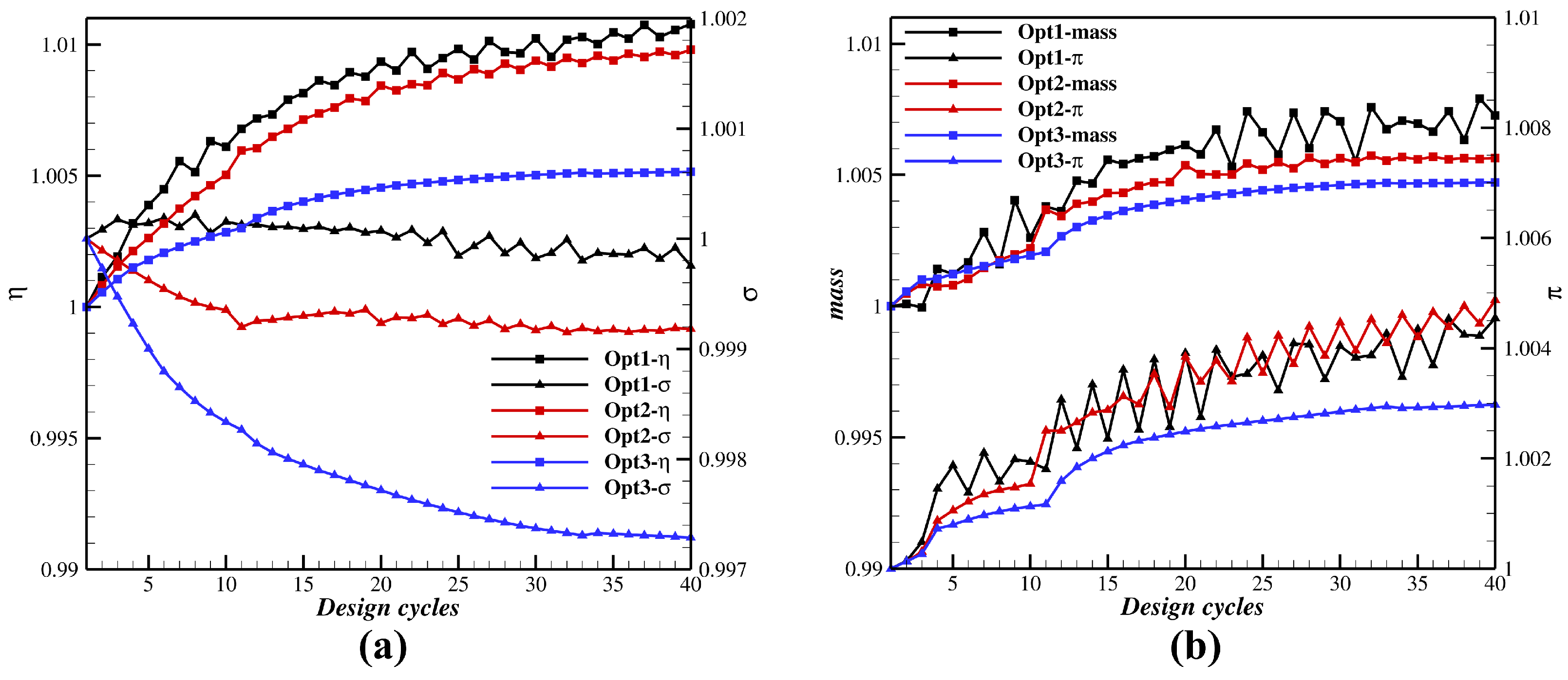
Figure 12 illustrates the convergence histories of the optimization with the Pareto solutions Opt1, Opt2, and Opt3. In forty optimization cycles, η and σ exhibit good convergence, while π and mass flow rate are also converged with weak zigzags. The aerodynamic and structural performance parameters of Opt1, Opt2, and Opt3 and the relative variations in the optimized blades compared to the original blade are given in Table 2.
The optimized blade Opt1 shows the most significant improvement in η , but the MES remains almost unchanged. The blade Opt2 experiences a 0.98% increase in η and a 2.96% reduction in MES, resulting in noticeable improvements in both aerodynamic and structural performance. The blade Opt3 exhibits the most significant decrease in MES. The reduction in MES is 7.90%, while the increase in η is 0.51%. Moreover, the variations of mass flow rate and total pressure ratio in the optimized blades do not exceed 0.65% and 0.49%, respectively, demonstrating strictly enforced constraints.
To further verify the effectiveness of aero-structural MDO in reducing maximum stress, the structural performance of the blades Opt1, Opt2, and Opt3 is calculated using the commercial program. The average percentage deviations in maximum stress, as defined by Equation (6), are calculated for both the maximum von Mises stress obtained using the commercial program and the MES calculated via the ESM. Figure 13 compares the average percentage deviations, and the results of the two methods are close.
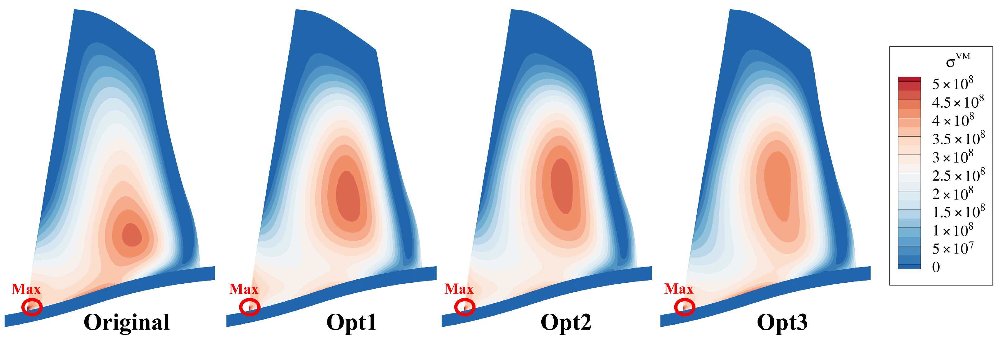
Figure 14 presents the distributions of von Mises stress on the original and the three optimized blades. The von Mises stress is calculated using the commercial program. It is known that the stress reaches its maximum at the LE near the hub for all the blades, while it reaches its minimum at the TE of the blade tip. It is interesting that after optimization, the stress on the middle spans is significantly increased, which probably results in increased mean von Mises stress. However, it is noteworthy that the optimization design primarily focuses on minimizing the maximum stress, which plays a more significant role in extending the material’s service life.
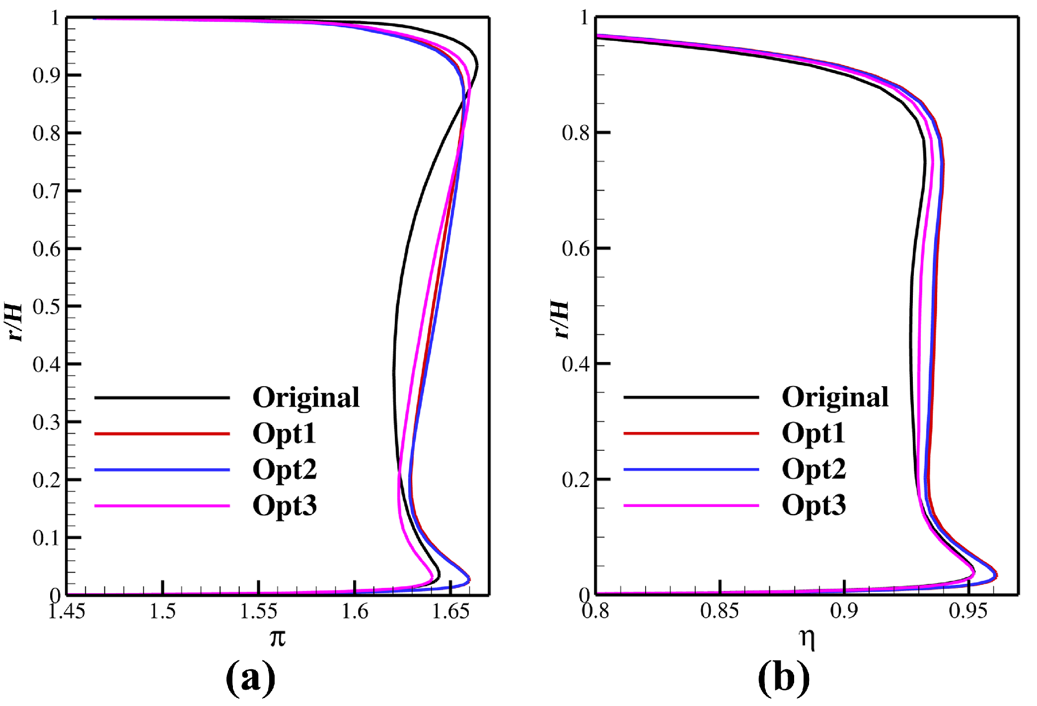
Figure 15 shows the spanwise distributions of π and η at the outlet for the original and the three optimized blades. Through optimization, the aerodynamic loads on the blade are redistributed on the whole span. The aerodynamic loads for the optimized blades are lower on the spans close to the blade tip due to the weakened shock wave. On the other hand, the weakened shock wave leads to a decrease in flow loss and an increase in adiabatic efficiency, as shown in Figure 15b. On the middle spans, the aerodynamic loads of the optimized blades increase, which favors the constraint of total pressure ratio in the optimization. Correspondingly, the adiabatic efficiency at the middle spans increases for all the optimized blades and the highest gains in adiabatic efficiency are obtained for Opt1.
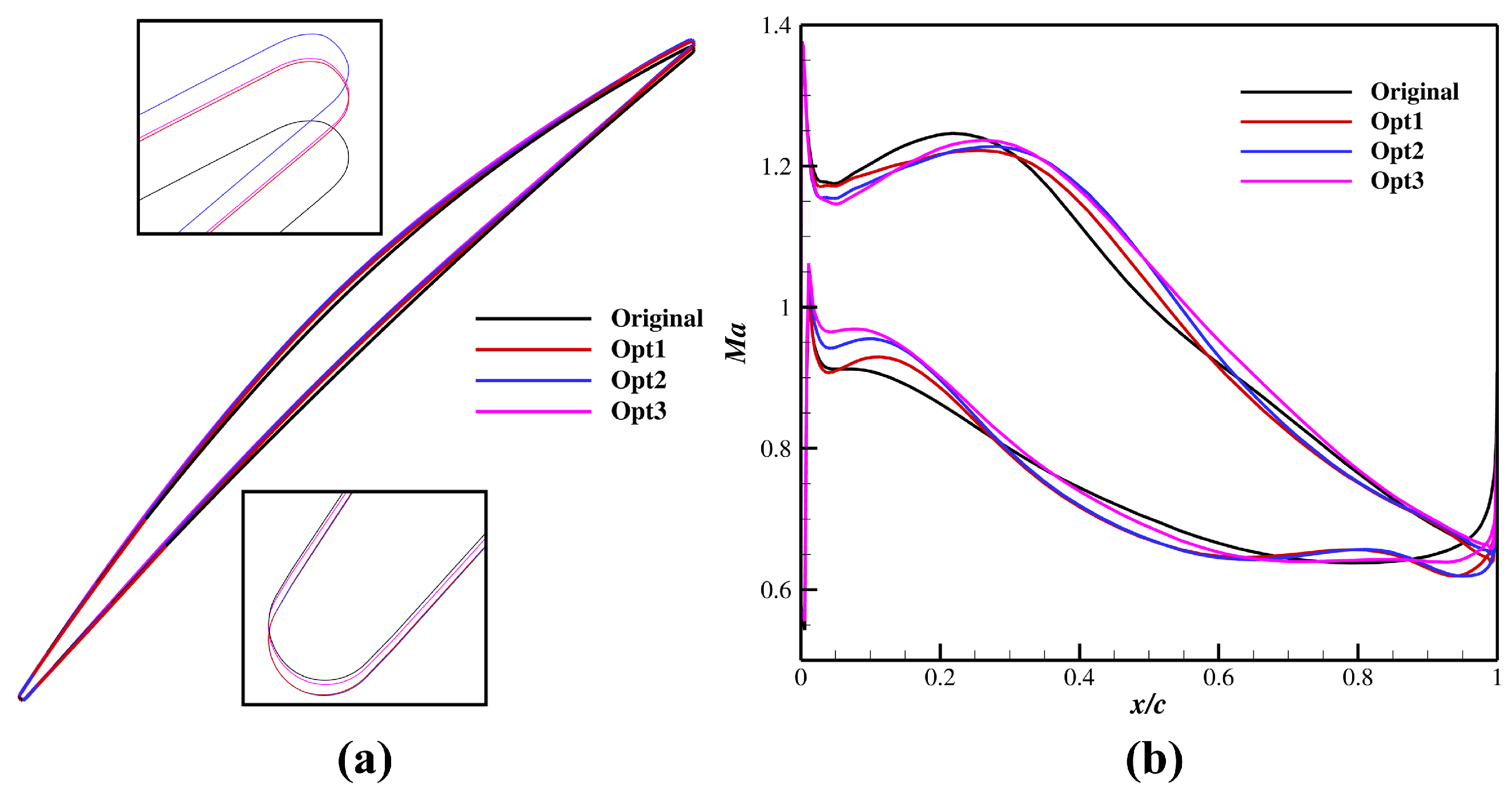
Figure 16 shows the blade profiles and the corresponding distributions of the isentropic Mach number on the blade at 90% span. For better observation, the blade profiles near the LE and TE are enlarged. Generally, all the optimized blades are slightly twisted in the anti-clockwise direction compared with the original blade. In such cases, the flow incidence angle decreases and the flow on the suction side decelerates, which is supposed to affect the downstream flow. It can be observed in Figure 16b that the original blade exhibits a pressure spike near the LE on the suction side, which is considered one major cause of the downstream flow loss. In contrast, the spikes of the optimized blades are noticeably reduced. Furthermore, strong shock waves appear at approximately 70% chord length on the suction side and 20% chord length on the pressure side of the original blade. After optimization, the strength of the shock wave significantly decreases and the associated shock losses can be reduced.
Figure 17 shows the blade profiles and the corresponding distributions of the isentropic Mach number on the blade at 50% span. Similar to the results in Figure 16, the blade profiles of the optimized blades are slightly twisted in the anti-clockwise direction. In such cases, the flow on the suction side decelerates, which favors the downstream movements of the shock wave for the optimized blades. Moreover, the curvature of the suction side decreases after optimization, which favors a weakening of the shock wave. As shown in Figure 17b, the shock wave on the suction side of the blades Opt1, Opt2, and Opt3 moves downstream and the Mach number before the shock slightly decreases. As a result, the aerodynamic load on this span increases and the shock loss decreases.

5. Conclusions

In this study, an algebraic method for calculating the maximum stress of turbomachinery blades without solving the structure equation is introduced, referred to as the equivalent stress model, to significantly reduce the computational cost of numerical optimization. Assisted by the ESM, an aero–structural multi-disciplinary design optimization method for rotor blades is developed, validated, and applied to the adjoint-based optimization of the transonic compressor rotor blade NASA Rotor 67. The results are presented and discussed, and our conclusions are as follows:
(1) The proposed ESM demonstrates high efficiency and acceptable accuracy in calculating the maximum equivalent stress as validated against the commercial program. Moreover, the ESM is universally applicable to the optimization of both rotor and stator blades. For stator blades, only the bending moment induced by aerodynamic loads needs to be calculated to determine the MES.
(2) The adjoint-based aero–structural optimization assisted by flow simulation and the ESM requires the solutions of only the RANS equations and the corresponding adjoint equations, making the adjoint-based MDO easier to be implemented, more practical, and lower cost. The aero–structural MDO minimizes the MES while maximizing the adiabatic efficiency is regarded as a multi-objective optimization problem and the Pareto front can be successfully determined. Among the three selected Pareto solutions, the maximum reduction in MES is 7.90% and the maximum increase in adiabatic efficiency is 1.06%.
(3) For the three optimized blades, the profiles on the outer spans, where the shock wave appears, are twisted in the anti-clockwise direction, and the maximum curvature of the suction side is reduced. These geometric modifications favor flow deceleration on the suction surface and facilitate the downstream movement of the shock wave, thereby reducing both the boundary flow loss and shock loss.

Author Contributions

Conceptualization, J.L. (Jiaxing Li) and J.L. (Jiaqi Luo); methodology, J.L. (Jiaxing Li) and J.L. (Jiaqi Luo); software, Z.F.; validation, J.L. (Jiaxing Li) and Z.F.; formal analysis, J.L. (Jiaxing Li); investigation, J.L. (Jiaxing Li); resources, J.L. (Jiaqi Luo); data curation, J.L. (Jiaxing Li) and Z.F.; writing—original draft preparation, J.L. (Jiaxing Li); writing—review and editing, J.L. (Jiaqi Luo); visualization, J.L. (Jiaxing Li); supervision, J.L. (Jiaqi Luo); project administration, J.L. (Jiaqi Luo); funding acquisition, J.L. (Jiaqi Luo). All authors have read and agreed to the published version of the manuscript.

Funding

This research was funded by the Zhejiang Provincial Natural Science Foundation of China (Grant no. LXR22E060001) and the National Science and Technology Major Project (Grant no. 2017-II-0006-0020).

Data Availability Statement

The data will be made available upon request.

Conflicts of Interest

Author Zhen Fu was employed by the company Windey Energy Technology Group Co., Ltd. The remaining authors declare that the research was conducted in the absence of any commercial or financial relationships that could be construed as a potential conflict of interest.

Abbreviations

ADAdjoint method
CFDComputational fluid dynamics
CSMComputational structural mechanics
ESMEquivalent stress model
FDMFinite difference method
LELeading edge
MDOMulti-disciplinary design optimization
MESMaximum equivalent stress
RANSReynolds-averaged Navier–Stokes
TETrailing edge

References

  1. Pouzadoux, F.; Reydellet, G.; Taillefer, E.; Masmoudi, M. Introduction of multi-disciplinary optimization in compressor blade design. In Proceedings of the 12th AIAA/ISSMO Multidisciplinary Analysis and Optimization Conference, Victoria, BC, Canada, 10–12 September 2008. [Google Scholar]
  2. Li, J.; Luo, J.; Liu, Y.; Han, Z. Static aeroelasticity analysis of a rotor blade using a Gauss-Seidel fluid-structure interaction method. Adv. Aerodyn. 2023, 5, 23. [Google Scholar] [CrossRef]
  3. Lian, Y.; Liou, M.S. Aerostructural optimization of a transonic compressor rotor. J. Propuls. Power 2006, 22, 880–888. [Google Scholar] [CrossRef]
  4. Sivashanmugam, V.K.; Arabnia, M.; Ghaly, W. Aero–structural optimization of an axial turbine stage in three-dimensional flow. In Proceedings of the ASME Turbo Expo 2010: Power for Land, Sea, and Air, Glasgow, UK, 14–18 June 2010. [Google Scholar]
  5. Luo, C.; Chen, J.; Liu, Y.; Xiang, H. Multidisciplinary design optimization with multiple degrees of freedom for an axial compressor based on data-driven. In Proceedings of the ASME Turbo Expo 2024: Turbomachinery Technical Conference and Exposition, London, UK, 24–28 June 2024. [Google Scholar]
  6. Nadarajah, S.; Jameson, A. A comparison of the continuous and discrete adjoint approach to automatic aerodynamic optimization. Can. J. Earth Sci. 2013, 43, 1445–1466. [Google Scholar]
  7. Walther, B.; Nadarajah, S. Adjoint-based constrained aerodynamic shape optimization for multistage turbomachines. J. Propuls. Power 2015, 31, 1298–1319. [Google Scholar] [CrossRef]
  8. Wang, D.; He, L. Adjoint aerodynamic design optimization for blades in multistage turbomachines: Part I methodology and verification. J. Turbomach. 2010, 132, 021011. [Google Scholar] [CrossRef]
  9. Wu, H.; Da, X.; Wang, D. Multi-row turbomachinery aerodynamic design optimization by an efficient and accurate discrete adjoint solver. Aerospace 2023, 10, 106. [Google Scholar] [CrossRef]
  10. Martins, J.; Alonso, J.; Reuther, J. High-fidelity aero–structural design optimization of a supersonic business jet. J. Aircraft. 2002, 41, 523–530. [Google Scholar] [CrossRef]
  11. Martins, J.; Alonso, J.; Reuther, J. A coupled-adjoint sensitivity analysis method for high-fidelity aero–structural design. Optim. Eng. 2005, 6, 33–62. [Google Scholar] [CrossRef]
  12. Marcelet, M.; Peter, J.; Carrier, G. Sensitivity analysis of a strongly coupled aero–structural system using direct and adjoint methods. In Proceedings of the 12th AIAA/ISSMO Multidisciplinary Analysis and Optimization Conference, Victoria, BC, Canada, 10–12 September 2008. [Google Scholar]
  13. Lei, R. Aerostructural Optimization and Design of Wing Based on Adjoint Method. Ph.D. Thesis, Northwestern Polytechnical University, Xi’an, China, 2021. [Google Scholar]
  14. He, L.; Wang, D. Concurrent blade aerodynamic-aero-elastic design optimization using adjoint method. J. Turbomach. 2011, 133, 011021. [Google Scholar] [CrossRef]
  15. Wu, H.; Yang, M.; Wang, D.; Huang, X. Efficient forced response minimization using a full-viscosity discrete adjoint harmonic balance method. AIAA J. 2024, 62, 3644–3661. [Google Scholar] [CrossRef]
  16. Mueller, L.; Verstraete, T.; Schwalbach, M. Adjoint-based multidisciplinary, multipoint optimization of a radial turbine considering aerodynamic and structural performances. In Proceedings of the ASME Turbo Expo 2019: Turbomachinery Technical Conference and Exposition, Phoenix, AZ, USA, 17–21 June 2019. [Google Scholar]
  17. Cuciumita, C.; John, A.; Qin, N.; Shahpar, S. Structurally constrained aerodynamic adjoint optimisation of highly loaded compressor blades. In Proceedings of the ASME Turbo Expo 2021: Turbomachinery Technical Conference and Exposition, Virtual, 7–11 June 2021. [Google Scholar]
  18. Yang, H.; Gong, S.; Yi, L.; Tang, J.; Wang, D.; Huang, S.; Xu, S. Stress sensitivity analysis for a wide-chord fan blade using an adjoint method. Chin. J. Aeronaut. 2024, 37, 103–117. [Google Scholar] [CrossRef]
  19. Strazisar, A.J.; Powell, J.A. Laser anemometer measurements in a transonic axial-flow fan rotor. J. Eng. Power 1981, 103, 430–437. [Google Scholar] [CrossRef]
  20. Luo, J.; Zhu, Y.; Tang, X.; Liu, F. Flow reconstructions and aerodynamic shape optimization of turbomachinery blades by POD-based hybrid models. Sci. China Technol. Sci. 2017, 60, 1658–1673. [Google Scholar] [CrossRef]
  21. Luo, J.; Fu, Z.; Li, J. Aero–structural design optimization of a transonic fan rotor using an adaptive POD-based hybrid surrogate model. Aerospace 2025, 12, 504. [Google Scholar] [CrossRef]
  22. Liu, F.; Jameson, A. Cascade flow calculations by a multigrid euler method. J. Propuls. Power. 1993, 9, 90–97. [Google Scholar] [CrossRef]
  23. Liu, F.; Jameson, A. Multigrid navier-stokes calculations for three-dimensional cascades. AIAA J. 1993, 31, 1785–1791. [Google Scholar] [CrossRef]
  24. Spalart, P.R.; Allmaras, S.R. A one-equation turbulence model for aerodynamic flows. In Proceedings of the 30th Aerospace Sciences Meeting and Exhibit, Reno, NV, USA, 6–9 January 1992. [Google Scholar]
  25. Jameson, A. Solution of the euler equations for two dimensional transonic flow by a multigrid method. Appl. Math. Comput. 1983, 13, 327–355. [Google Scholar] [CrossRef]
  26. Li, J.; Luo, J.; Liu, F.; Zheng, Y.; Han, Z. Performance sensitivity analysis and aerodynamic optimization of compressor cascades by a turbulence adjoint method. AIP Adv. 2024, 14, 115307. [Google Scholar] [CrossRef]
  27. Hascoet, L.; Pascual, V. The tapenade automatic differentiation tool: Principles, model, and specification. ACM Trans. Math. Softw. 2013, 39, 20. [Google Scholar] [CrossRef]
  28. Hicks, R.M.; Henne, P.A. Wing design by numerical optimization. J. Aircraft. 1978, 15, 407–412. [Google Scholar] [CrossRef]
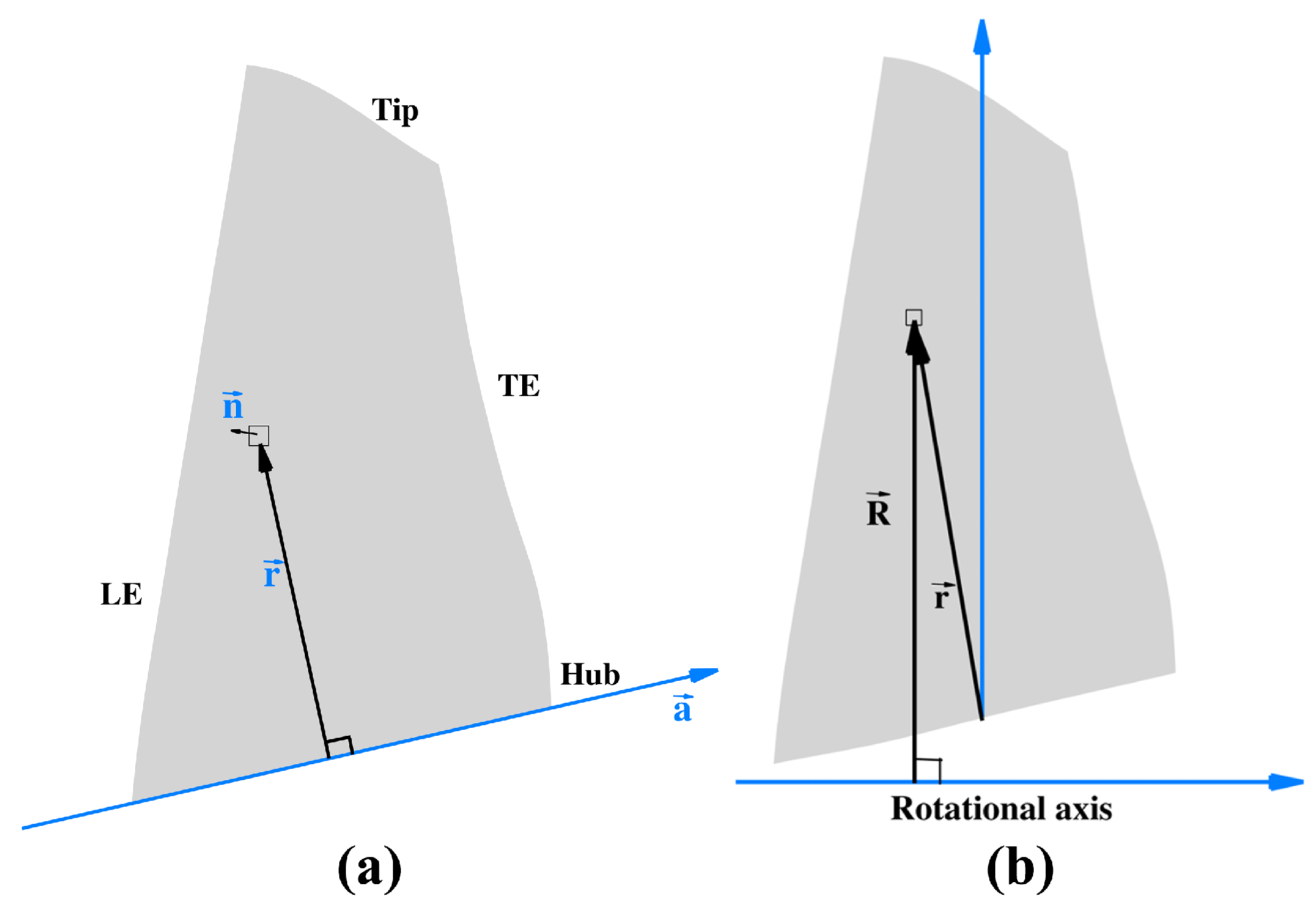
Figure 1. Schematic illustrations for calculating the bending moment resulting from (a) aerodynamic loads and (b) centrifugal force.
Modelling 06 00125 g001
Figure 2. Principal axes ( η and ξ ) of inertia at the blade root.
Modelling 06 00125 g002
Figure 3. Blade profiles in the meridional plane of the original blade (in gray) and swept blades (in red), with numbers (1) to (6) indicating the serial numbers of the swept blades.
Modelling 06 00125 g003
Figure 4. Comparison of bending moment resulting from (a) aerodynamic loads and (b) centrifugal force.
Modelling 06 00125 g004
Figure 5. Average percentage deviations in the maximum stress for different blades.
Modelling 06 00125 g005
Figure 6. Topology of the grid for flow computation.
Modelling 06 00125 g006
Figure 7. Flow solutions of different grids.
Modelling 06 00125 g007
Figure 8. Spanwise distributions of flow solutions under operation conditions near PE: (a) total pressure ratio π ; (b) flow turning angle β ; (c) total temperature ratio θ .
Modelling 06 00125 g008
Figure 9. Procedure of aero–structural MDO assisted by the ESM and gradient-based optimization method.
Modelling 06 00125 g009
Figure 10. Sensitivities for 25% and 75% spans: 1–13, suction side; 14–26, pressure side.
Modelling 06 00125 g010
Figure 11. Pareto solutions for aero-structural multi-objective optimization.
Modelling 06 00125 g011
Figure 12. Variations of performance parameters in design optimization: (a) η and MES and (b) π and mass flow rate.
Modelling 06 00125 g012
Figure 13. Average percentage deviations in maximum stress for the optimized blades.
Modelling 06 00125 g013
Figure 14. Distributions of von Mises stress in the original and the three optimized blades.
Modelling 06 00125 g014
Figure 15. Spanwise distributions of performance parameters at the outlet of both the original and optimized blades: (a) π ; (b) η .
Modelling 06 00125 g015
Figure 16. Comparisons of optimization results at 90% span: (a) blade profiles; (b) isentropic Mach number distributions.
Modelling 06 00125 g016
Figure 17. Comparison of optimization results at 50% span: (a) blade profiles; (b) isentropic Mach number distributions.
Modelling 06 00125 g017
Table 1. Specifications of NASA Rotor 67 [19].
ParameterValue
Design rotation speed (rpm)16,043
Blade number22
Tip clearance (mm )1.0
Design pressure ratio1.63
Design mass flow rate (kg/s)33.25
Inlet total pressure (Pa)101,325.0
Inlet total temperature (K)288.15
Table 2. Optimization results.
η /% σ /Pa m ˙ /kg· s−1 π
Original91.195.47 × 10 834.141.635
Opt192.16 (1.06%)5.43 × 10 8 (−0.70%)34.37 (0.65%)1.643 (0.49%)
Opt292.09 (0.98%)5.31 × 10 8 (−2.96%)34.34 (0.59%)1.643 (0.49%)
Opt391.65 (0.51%)5.04 × 10 8 (−7.90%)34.31 (0.50%)1.640 (0.31%)
Disclaimer/Publisher’s Note: The statements, opinions and data contained in all publications are solely those of the individual author(s) and contributor(s) and not of MDPI and/or the editor(s). MDPI and/or the editor(s) disclaim responsibility for any injury to people or property resulting from any ideas, methods, instructions or products referred to in the content.