Article

An Analytical Thermal Model for Coaxial Magnetic Gears Considering Eddy Current Losses

by
Panteleimon Tzouganakis
1,*,
Vasilios Gakos
2,
Christos Papalexis
1,
Christos Kalligeros
2,
Antonios Tsolakis
1 and
Vasilios Spitas
2
1
Laboratory of Machine Elements and Vehicles, University of West Attica, 122 44 Egaleo, Greece
2
Laboratory of Machine Design, National Technical University of Athens, 157 80 Zografou, Greece
*
Author to whom correspondence should be addressed.
Modelling 2025, 6(4), 114; https://doi.org/10.3390/modelling6040114
Submission received: 1 August 2025 / Revised: 13 September 2025 / Accepted: 23 September 2025 / Published: 25 September 2025

Abstract

This work presents an analytical 2D model for estimating eddy current losses in the permanent magnets (PMs) of a coaxial magnetic gear (CMG), with a focus on loss minimization through magnet segmentation. The model is applied under various operating conditions, including different rotational speeds, load levels, and segmentation configurations, to derive empirical expressions for eddy current losses in both the inner and outer rotors. A 1D lumped-parameter thermal model is then used to predict the steady-state temperature of the PMs, incorporating empirical correlations for the thermal convection coefficient. Both models are validated against finite element analysis (FEA) simulations. The analytical eddy current loss model exhibits excellent agreement, with a maximum error of 2%, while the thermal model shows good consistency, with a maximum temperature deviation of 5%. The results confirm that eddy current losses increase with rotational speed but can be significantly reduced through magnet segmentation. However, achieving an acceptable thermal performance at high speeds may require a large number of segments, particularly in the outer rotor, which could influence the manufacturing cost and complexity. The proposed models offer a fast and accurate tool for the design and thermal analysis of CMGs, enabling early-stage optimization with minimal computational effort.

1. Introduction

Mechanical gears have been fundamental components in power transmission applications for centuries, with extensive research in optimizing tooth geometry and material selection for maximizing their operational characteristics. Despite these advancements, mechanical gears remain susceptible to issues such as wear and noise. As a consequence, a continuous need for lubrication and maintenance is required [1].
In contrast, magnetic gears—particularly those employing permanent magnets (PMs)—offer enhanced reliability due to the absence of physical contact and friction between rotating elements. These systems have demonstrated a high efficiency and torque density, while also being compact and exhibiting negligible torque ripple [2]. However, their efficiency tends to decrease at high rotational speeds.
Since their introduction in the early 21st century, coaxial magnetic gears (CMGs) [3] have attracted growing interest across various industrial areas, such as power generation [4,5] and aerospace applications [6]. Despite their complex design, analytical expressions for the scalar magnetic potential, magnetic flux density, and torque generation in CMGs have been established in the literature [7,8]. However, challenges such as limited torque density, slippage during acceleration/deceleration, and losses induced by eddy currents continue to hinder the widespread industrial adoption of CMGs [6]. In particular, eddy current losses become a critical concern at high rotational speeds [1]. These losses not only reduce efficiency but also lead to increased temperature in the PMs, potentially accelerating their degradation and affecting the long-term reliability of the system. As a result, thorough investigation and mitigation of eddy current losses are essential in the design and optimization of CMG-based drives.
CMGs have a complex design; therefore, the eddy current loss calculation requires a rigorous methodology that takes into account transient electromagnetic phenomena. Finite element analyses have been conducted in the literature [9,10] for the calculation of eddy current losses in the PMs of CMGs; however, the high computational cost hinders the initial stages of design and optimization [11]. The eddy current losses in the PMs can be estimated by calculating the current density distribution within the PMs at different time steps [11,12] using the analytical formulation of the magnetic field density in the CMG [13,14]. This result is subsequently integrated over time and divided by the system’s period to calculate the average eddy current losses. To mitigate these losses, circumferential magnet segmentation is implemented [12]. Researchers have also developed a 2D analytical model for calculating the eddy current losses through the analytical calculation of the scalar magnetic potential and vector magnetic potential [15]. The developed model was in excellent agreement with FEA models. Moreover, circumferential segmentations were included in the model and their effect on reducing the eddy current losses was established. Finally, it was demonstrated that the eddy current losses become significant in higher rotational speeds [16].
The thermal problem in the PMs of the CMG is a critical design concern, especially at high rotational speeds. Eddy current losses within the PMs generate heat, which can lead to elevated temperatures that degrade magnetic properties and reduce the overall performance [1]. NdFeB magnets, commonly used in CMGs, are particularly sensitive to temperature and may experience irreversible demagnetization if operational limits are exceeded. Effective thermal management is essential to maintain magnet integrity, ensure torque stability, and prolong system lifespan. However, due to the compact structure of CMGs and the low thermal conductivity of PMs, dissipating this heat is challenging. Therefore, accurate thermal modeling and loss prediction are vital during the design phase to prevent overheating and ensure reliable operation.
In this work, a model is developed to estimate eddy current losses in the PMs of a CMG considering various operating conditions and magnet segmentation strategies using an empirical formulation that combines high accuracy and low computational cost. Building on this loss estimation, the core contribution of the study is the development of a computationally efficient 1D lumped-parameter thermal model to predict the steady-state temperature of the PMs. The thermal model incorporates empirical correlations for the convective heat transfer coefficient and enables rapid thermal evaluation without relying on time-consuming simulations. Both the eddy current and thermal models are validated according to the finite element analysis (FEA), showing excellent agreement with minimal error. The novelty of this work lies in the integration of accurate analytical loss prediction with a fast thermal modeling approach, allowing for reliable temperature estimation in PMs under high-speed conditions. The proposed model could serve as a valuable design tool for CMG developers, enabling early-stage thermal analysis and design optimization with a significantly reduced computational cost.

2. Materials and Methods

2.1. Principles of CMGs

In Figure 1, a standard CMG is presented along with its important radii. The main parts of the CMG are two concentric iron rotors with PMs attached to them. Furthermore, a modulator ring consisting of ferromagnetic segments (with an angle δ ) is included to modulate the magnetic flux and enable the robust operation of the drive.
For the robust operation of a CMG, it is necessary that the sum of the pole-pairs of the inner ( p i n ) and outer ( p o u t ) rotor is equal to the number of ferromagnetic segments ( Q ) in the modulator ring, as shown in Equation (1).
p i n + p o u t = Q
Of the three concentric parts, one is typically fixed. For instance, if the inner rotor is the input, the modulator ring could be fixed and the output can be given from the outer rotor, or the outer rotor could be fixed and the output can be obtained from the modulator ring. For these two cases, the equivalent gear ratio is determined as follows [2,9]:
  • For a fixed modulator ring (considered in this study), the output is in the opposite direction of the input and the gear ratio ( G M ) is
G M = p o u t p i n
  • For a fixed outer rotor, the output is in the same direction of the input and the gear ratio ( G M ) is
G M = Q p i n

2.2. Two-Dimensional Analytical Model for Eddy Current Loss Calculation

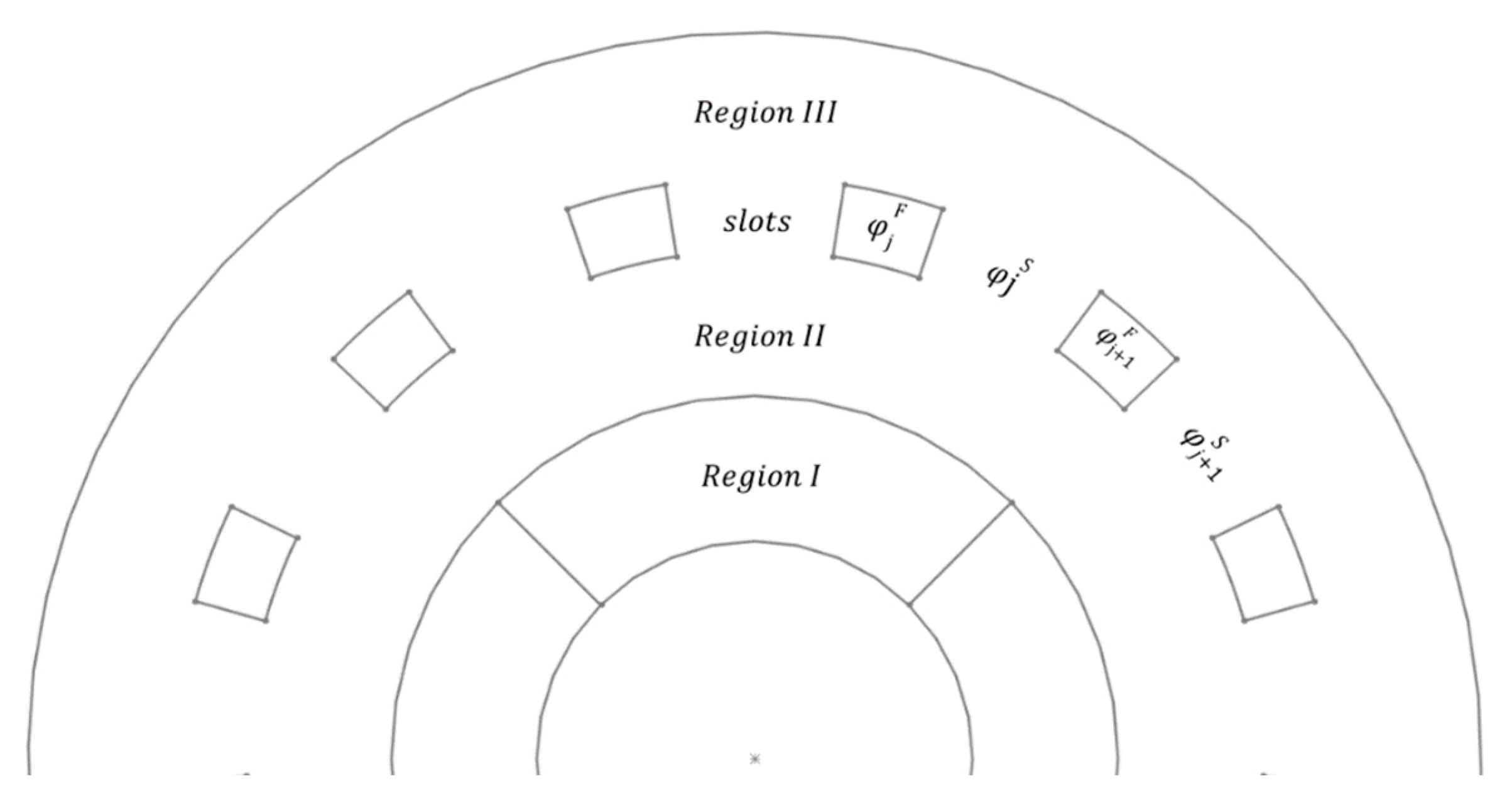
To calculate the losses in the permanent magnets (PMs), the vector magnetic potential ( A ) within the PMs must be determined. This vector potential can be obtained once the scalar magnetic potential ( φ ) has been evaluated. The scalar potential is computed by dividing the coaxial magnetic gear (CMG) into three regions, then calculating the contribution of each rotor PM to the magnetic potential across the entire CMG, and finally superimposing these contributions [7]. Figure 2 illustrates the three regions, taking into account the contribution of PMs in the inner rotor.
The scalar magnetic potential in each region is determined by solving Maxwell’s Equations (4)–(6). To enable the analytical solutions of the scalar magnetic potential, infinite permeability is assumed in the rotors and the ferromagnetic segments ( φ j F ) [7,8]. The assumption of infinite permeability is justified since the ferromagnetic segments of the modulator ring and the rotors are made of iron.
2 φ Ι r , θ = d i v M μ r   i n   R e g i o n   I
2 φ Ι I , I I I r , θ = 0   i n   R e g i o n s   I I ,   I I I
2 φ S r , θ = 0   i n   t h e   s l o t s
where ( M ) is the magnetization vector of the PMs and ( μ r ) the relative permeability.
Equations (4)–(6) can be solved analytically and the infinite series coefficients can be determined from the following boundary conditions [7]:
1.
Zero magnetic potential in radii ( r 1 ) and ( r 6 ).
2.
Continuity on both the magnetic potential and its radial derivative at the boundaries between regions.
3.
Continuity of the magnetic flux density through the slots at ( r 3 ) and ( r 4 ).
4.
The magnetic flux through the inner surface of the modulator ring should match the flux through the outer surface.
5.
The magnetic flux entering each ferromagnetic segment must equal the flux exiting it.
A similar process is implemented to account for the effect of the outer rotors’ PMs. Following the superposition of the scalar magnetic potential obtained from the inner and outer rotor, the vector magnetic potential ( A ) is calculated using Equations (7) and (8).
Β r k r , θ = μ 0 φ k r = 1 r A k θ
Β θ k r , θ = μ 0 φ k θ = A k r
where ( μ 0 ) is the vacuum permeability, and ( Β r k ) and ( B θ k ) are the radial and tangential flux densities of a point in the PMs of the inner and outer rotor, while ( k ) denotes the inner or outer rotor (k: in or out).
As a result, the eddy current losses in the PMs are calculated using Equations (9)–(11) [11,12].
P e d d y k = L Θ p k 0 Θ p k 1 σ S P M k ( ( J k ) 2 r d r d θ ) d θ 0 k
J k ( r , θ , θ 0 k ) = σ ω k A k θ 0 k + C k ( θ 0 k )
C k ( θ 0 k ) = 1 S P M k   S P M k σ ω k A k θ 0 k r d r d θ
where ( σ ) is the conductivity of the PMs, ( S P M k ) is the area of each PM, ( J k ) is the eddy current density, and ( C k ) is a term. Finally, ( θ 0 k ) and ( ω k ) are the rotation angle and the rotational speed of each rotor, respectively, while ( Θ p k ) is defined as the angle of rotation of each rotor during a period of the system, which is determined from the greatest common divisor of the pole-pairs of each rotor.
Finally, the eddy current losses depend on the relative position of the inner and outer rotor. The relative position is dependent on the applied load on the CMG. This dependence is determined according to Equations (12) and (13) [7].
T i n = M s t a l l , i n sin ( p i n θ i n + p o u t θ o u t )
T o u t = M s t a l l , o u t sin ( p i n θ i n + p o u t θ o u t )
where ( θ i n ) and ( θ o u t ) are the positions of the two rotors, and ( T i n ) and ( T o u t ) are the applied torques on the inner and outer rotor, respectively, while ( M s t a l l , i n ) and ( Μ s t a l l , o u t ) are their stall torques that are calculated analytically from the scalar magnetic potential in [7].

2.3. Circumferential Segmentation of PMs

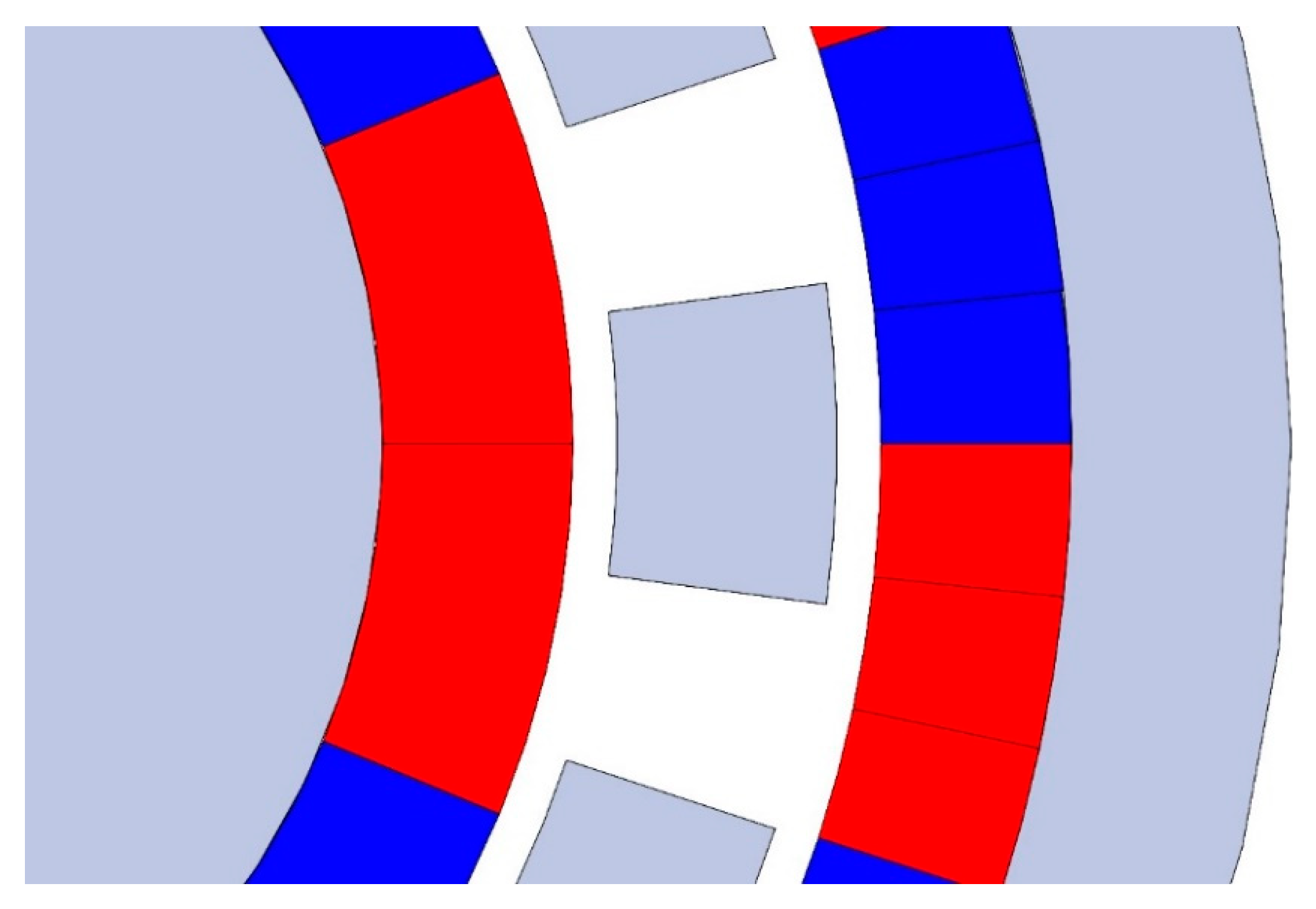
Eddy current losses in permanent magnets (PMs) can be mitigated by segmenting them either axially or circumferentially. This study concentrates on circumferential segmentation. To incorporate this into the analytical model, the angular domain over which the integration is carried out must be divided by the total number of segments ( K i n , K o u t ) for each rotor, as illustrated in Equation (14) [11].
θ θ 0 , θ 0 + π p i n 1 K i n ,   θ θ 0 , θ 0 + π p o u t 1 K o u t
In Figure 3, a typical circumferential segmentation is depicted. In the inner rotor, two segmentations are made, while in the outer rotor, three are made.

2.4. Eddy Current Losses in a CMG-Empirical Formula

From several studies in the literature, it has been observed that the power losses due to eddy currents in the PMs of the two rotors could be described in the form of
P e d d y k = f ( p i n θ i n + p o u t θ o u t , ω k )
where ( f ) is a function.
In the function of Equation (15), it was observed that the relative position of the two rotors and the angular velocity were independent in the resulting power losses due to eddy currents. Therefore, the power losses can be described in the following form:
P e d d y k = f 1 p i n θ i n + p o u t θ o u t f 2 ω k
where ( f 1 ) and ( f 2 ) are two functions.
From several studies in the literature, it is observed that for the case of the angular velocity, the eddy current losses can be approximated with [9,10,11,12]
  f 2 θ ˙ k = c ω k 2
where ( c ) is a constant.
Furthermore, it can be observed that for the case of relative position, the eddy current losses can be approximated with [15]
f 1 p i n θ i n + p o u t θ o u t = c 1 + c 2 p i n θ i n + p o u t θ o u t
where ( c 1 ) and ( c 2 ) two constants.
As a result, the eddy current losses can be approximated as
P e d d y k = a k + b k p i n θ i n + p o u t θ o u t ω k 2
where ( a k ) and ( b k ) are coefficients that can be calculated after the simulation of the eddy current losses in two different relative position at a given angular velocity. These coefficients are dependent on the constitutive geometrical parameters of the CMG and PMs.
In addition, the eddy current losses are dependent on the number of segmentations in each PM. As the number of segmentation increases, the eddy current losses tend to zero. The eddy current losses follow the following function [15,17]:
P e d d y k K k = λ 3 , k λ 1 , k 2 + λ 2 , k 2 K k 2
where ( K k ) is the number of segmentations of each PM and ( λ 1 , k ), ( λ 2 , k ), and ( λ 3 , k ) are constants that can be obtained after fitting the results of the eddy current losses on each rotor for different numbers of segmentations.
As a result, the eddy current losses for each rotor is
P e d d y k = λ 3 , k λ 1 , k 2 + λ 2 , k 2 K k 2 a k + b k p i n θ i n + p o u t θ o u t ω k 2

2.5. Thermal Model

After the calculation of the eddy current losses in the two rotors, the expected steady-state temperature can be determined using
P e d d y k = h k A k ( T k T a m b )
where ( h k ) is the thermal convection coefficient and ( A k ) is the surface area of each rotor, while ( T k ) and ( T a m b ) are the steady-state and ambient temperature, respectively. The ambient temperature is considered constant for the scope of this research.
The surface area of each rotor is calculated from
A i n = 2 π r 2 L + 2 π r 2 2
A o u t = 2 π r o u t + r 5 L + 2 π ( r o u t 2 r 5 2 )
The thermal convection coefficient depends on the angular velocity of each rotor. A higher rotational speed would yield a higher thermal convection coefficient and therefore the temperature increment would be slightly moderated due to the higher eddy current losses. For the calculation of the thermal convection coefficient, the following empirical formula is used, according to reference [18]:
h k = N u k k a i r D k
where ( N u k ) is the Nusselt number on each rotor, ( k a i r ) is the thermal conductivity of air, and ( D k ) is the diameter of the respective rotor. The Nusselt number is calculated from
N u k = 0.026 R e k 0.8 P r 0.33  
where ( R e k ) is the Reynolds number on each rotor and ( P r ) is the Prandtl number. The Reynolds number is calculated from
R e k = 2 ω k r k 2 ν
where ( ν ) is the kinematic viscosity of air.

2.6. Methodology

In Table 1, the parameters of the case study used are shown. The PMs of the CMG are N52 NdFeB magnets with a remanence of 1.47 T.
An algorithm implementing the developed analytical model was developed in MATLAB 2020a. Then, a transient finite element (FE) model was developed to validate the analytical results, using Ansys Maxwell. For the validation case with the FE simulation, a rotational speed of 2500 rpm in the inner rotor is considered, while the applied loads are set to be equal to the respective stall torques. The time step is chosen such that the inner rotor rotates by 2°, corresponding to a 0.8° rotation of the outer rotor. This time step provides high computational accuracy while keeping the number of time steps per period manageable.
Following the eddy current calculation, the steady-state temperature in the two rotors is determined with the analytical formulation. In addition, a steady-state thermal FE model was developed to validate the accuracy of the proposed thermal analytical model. The FE model was created in ANSYS 2024 R2 containing the two rotors and the modulator ring. The eddy current losses in the magnets were simulated to create heat during power generation in the magnet bodies both in the inner and the outer rotor. The convection coefficients were calculated analytically for each rotor depending on their rotation speed, similarly to the proposed analytical model. The mesh contained hexa-elements and the mesh size was determined at 5mm after mesh convergence, showing no significant change in temperature distribution with further mesh refinement. The material used for the modulator ring and the yokes of each rotor was iron, while the NdFeB magnets were considered as PMs. The parameters for the thermal simulation are presented in Table 2.

3. Results and Discussion

3.1. Eddy Current Loss Calculation and Comparison with FEA

In Figure 4, the analytical eddy current losses in the inner and outer rotor as a function of the inner rotor angular velocity are presented. Moreover, the eddy current losses are calculated through an FEA. It can be observed that the analytical model displays excellent coherence, with a maximum error of 2%. Furthermore, the quadratic relation of the eddy current losses with the angular velocity is observed, as expected according to Equation (17).
To determine the constants ( a k ), ( b k ), ( λ 1 , k ), ( λ 2 , k ), and ( λ 3 , k ), used in the empirical formula of Equation (21), the analytical model was used for various applied outer loads for a constant rotational speed of the inner rotor at 2500 rpm.
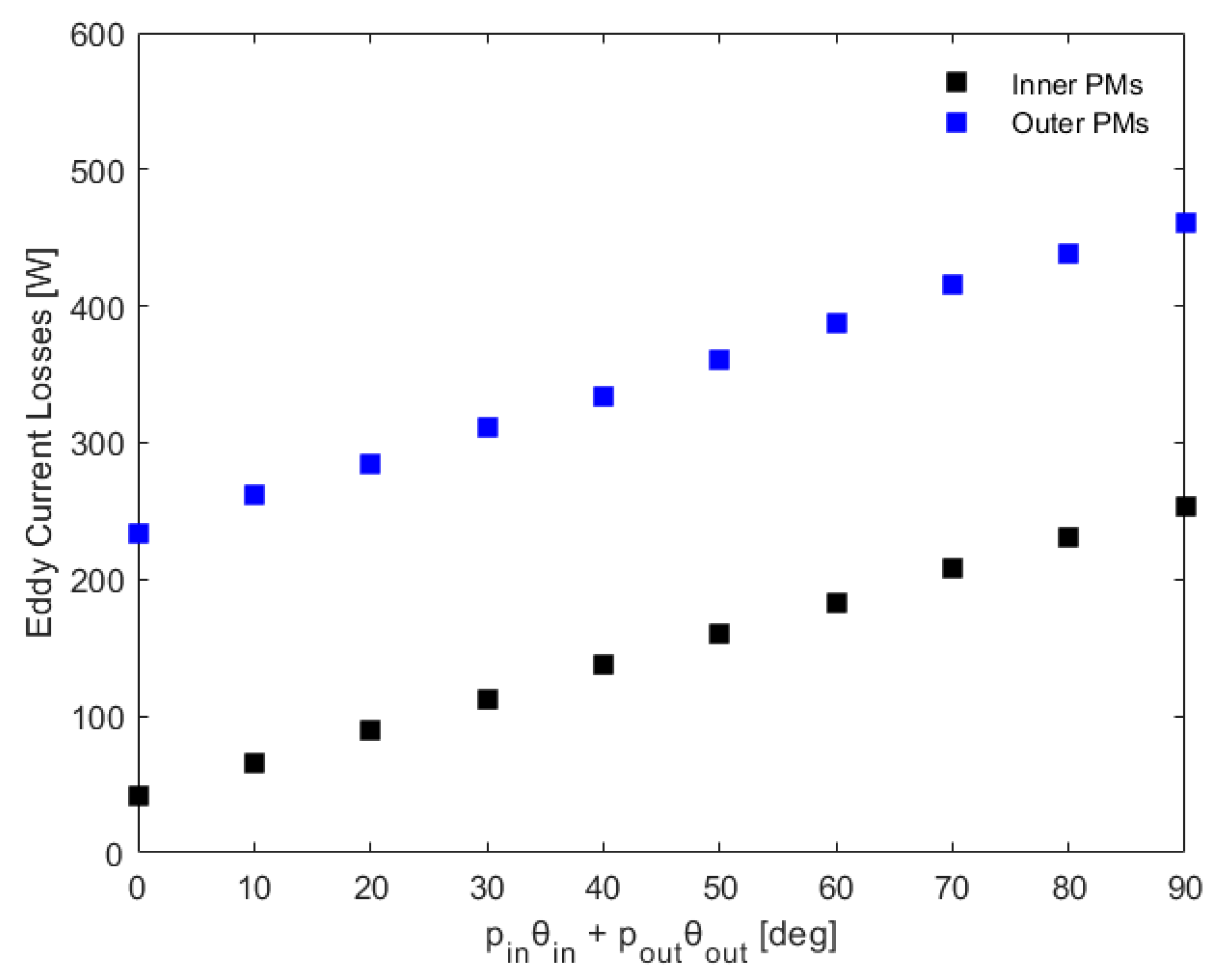
In Figure 5, the analytical eddy current losses in the inner and outer rotor are calculated for different applied loads that lead to different relative angles in the two rotors according to Equations (12) and (13). The linear relation of the eddy current losses with respect to the relative angle is observed as expected from Equation (18).
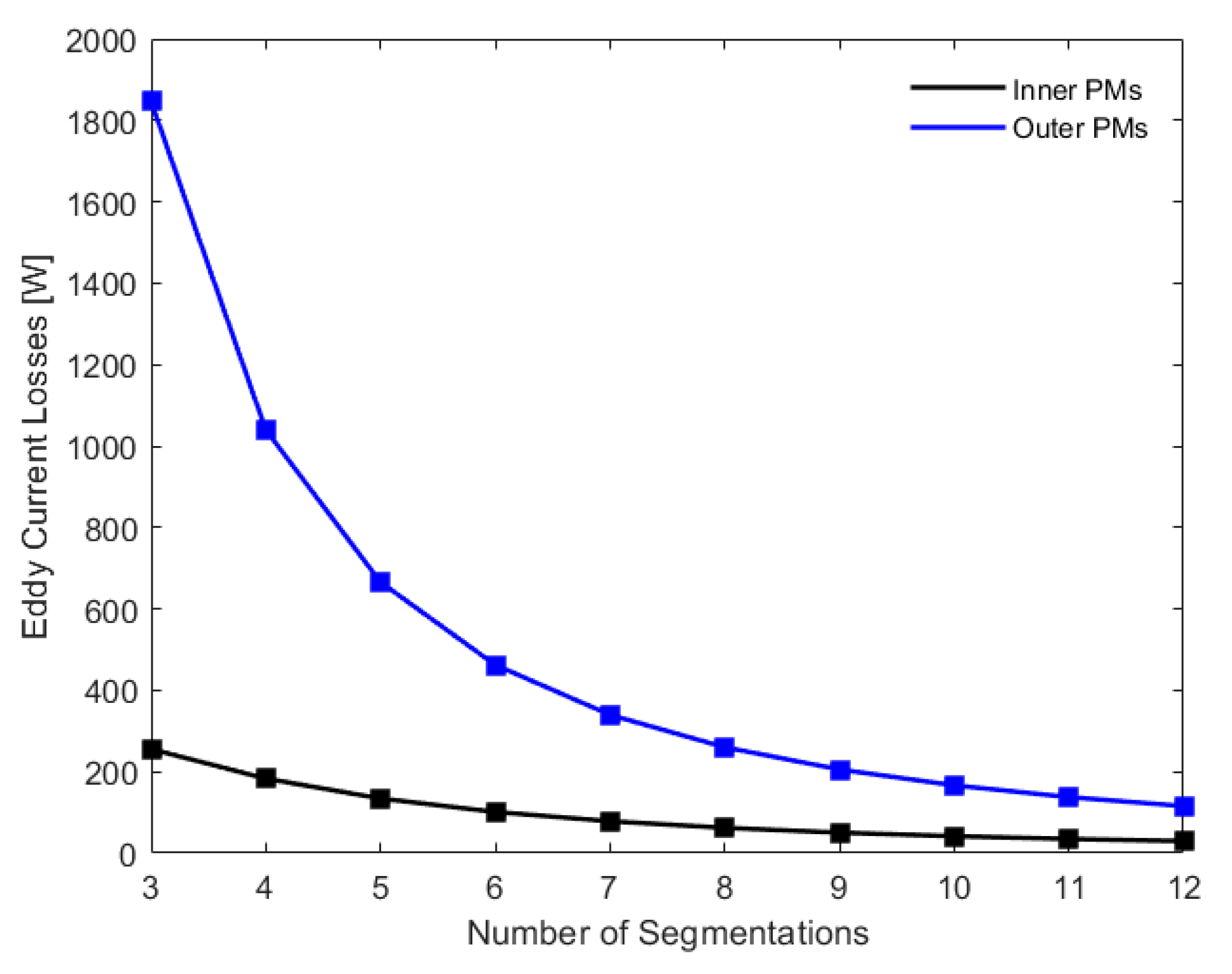
In Figure 6, the analytical eddy current losses in the inner and outer rotor are calculated as a function of the number of circumferential segments in each rotor, respectively. The minimum number of segmentations considered is three while the maximum is twelve. The eddy current losses are calculated for an angular velocity of 2500 rpm in the inner rotor. It can be observed that the eddy current losses significantly decrease with the number of segments. The inverse quadratic relation of the eddy current losses with respect to the number of segments is observed as expected according to Equation (20).
Therefore, from Equation (21) and the results obtained in Figure 4, Figure 5 and Figure 6, the constants ( a k ), ( b k ), ( λ 1 , k ), ( λ 2 , k ), and ( λ 3 , k ) can be calculated through a fitting function. The constants for the inner and outer rotors are summarized and presented in Table 3.

3.2. Steady-State Temperature Calculation and Comparison with FEA

In Figure 7, the thermal convection coefficient for the inner and outer rotor is presented with respect to the angular velocity of the inner rotor. As expected with higher angular velocities, the thermal convection coefficient is increased. The inner rotor showcases a higher value of thermal convection coefficient due to its higher rotational speed compared to the outer rotor, due to the gear ratio. The thermal convection coefficient exceeds a value of 100 W/m2/K for the inner rotor at 5000 rpm, while for the outer rotor, the value is approximately 70 W/m2/K.
In Figure 8, the steady-state temperature of the inner and outer rotors is depicted with respect to the inner rotor’s angular velocity. For the calculation of the steady-state temperature, the eddy current losses presented and the thermal convection coefficient in Figure 4 and Figure 7, respectively, for each rotor are taken into account.
As expected, with higher angular velocities, the steady-state temperature increases. It can be observed that the outer rotor has a substantially higher temperature in comparison to the inner rotor, a phenomenon that is attributed to the higher eddy current losses and lower values of the thermal convection coefficient. For the case of the inner rotor with an angular velocity of 2500 rpm, the inner and outer rotors’ steady-state temperatures are calculated as 80 °C and 95 °C, respectively. The temperatures of both the inner and outer rotors exceed 150 °C at an angular velocity of the inner rotor of 5000 rpm, a temperature above the maximum operating temperature of the N52 NdFeB magnets, suggesting that the number of segmentations selected in Table 1 is not sufficient.
An FEA validation for an angular velocity of 2500 rpm using the geometrical data and the results regarding the eddy current losses and thermal convection coefficient was conducted. The results of the FE simulation are presented in Figure 9 and Table 4.
From the summarized results in Table 4, it can be observed that the analytical results are in good coherence with the FEA results with a 5% deviation, which is attributed to the limitations of the 1D analytical model of Equation (22) that neglects thermal conduction phenomena and assumes a lumped system. This is the reason why the calculated temperature according to the analytical model is lower when compared to that found using the FE model. However, the analytical approach yields a result with a high accuracy and a lower computational cost.
From Figure 8, it is evident that at high angular velocities, the steady-state temperature surpasses the maximum operational temperature of the NdFeB magnets. Therefore, the number of segments could be increased to lower the eddy current losses and, consequently, the temperature of the PMs.
In Figure 10, the steady-state temperature, as calculated from the analytical model, is depicted with respect to the number of segmentations. The temperature is calculated for the case of a maximum load and angular velocity of 5000 rpm in the inner rotor. It can be observed that, as expected, the steady-state temperature decreases with the number of segmentations in the two rotors. With six segmentations in the inner and ten in the outer rotor, the steady-state temperatures are 74.7 °C and 82.5 °C, respectively, which are within the operational limits of the NdFeB magnets. Increasing the number of segmentations further will not have a significant effect and will only increase the manufacturing costs.

4. Discussion and Future Work

From the developed methodology, a high-accuracy and low-computational-cost model for calculating the eddy current losses in CMGs and, consequently, the steady-state temperature for any CMG geometry, rotational speed, or applied load. From the performed case studies, it was observed that the temperature of the PMs of the inner and outer rotors could exceed the operational values, especially at high rotational speeds. The high temperature could be mitigated with segmentations, as shown in Figure 10. However, an important parameter that should be considered is the manufacturability costs. For instance, according to Figure 10, ten segments are required in the outer rotor to reduce the temperature within the operational limits. However, considering that the outer rotor has ten pole-pairs, each segment would have an angle of 1.8° or, equivalently, an arc of 2.7 mm, which would significantly increase the manufacturing costs.
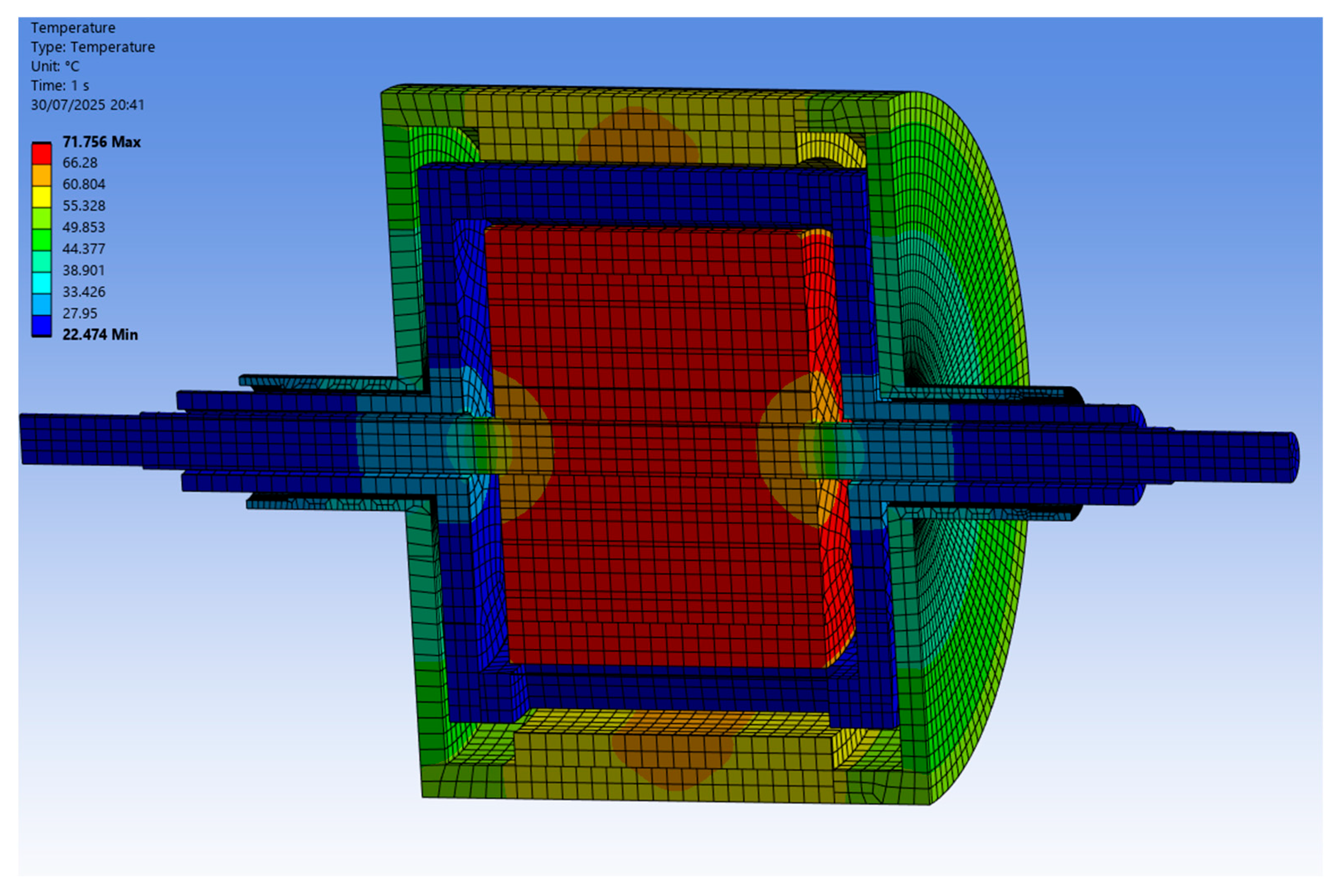
However, in our analysis so far, the torque carriers and the shafts used to transfer the torque to the rest of the powertrain have been neglected in the thermal modeling. By including a more detailed design, the heat losses will dissipate and the temperature will decrease. The results of this study are presented in Figure 11 and Table 5.
Comparing Table 4 and Table 5, it can be observed that the temperature in the outer rotor has dropped significantly with the inclusion of shafts and torque carriers in the model. This is attributed to the larger surface area of the outer rotor that is created by the outer rotor torque carrier.
In the future, a coupled computational fluid dynamics (CFD)–thermal analysis could be implemented for a more accurate assessment of the thermal convection coefficient, especially in the airgaps, including the effect of the modulator ring that will further increase the turbulence. Finally, to improve the accuracy of the thermal analysis, the effect of windage on temperature increases could be incorporated. However, this analysis would significantly increase the computational cost and was deemed beyond the scope of the present work. In addition, a techno-economic analysis could be implemented to establish the optimal design in terms of minimizing the eddy current losses and their effect on the induced temperature of the PMs of the CMG and establishing the optimal number of segmentations required.

5. Conclusions

In the present research, an analytical model is developed to determine the eddy current losses in the PMs of a CMG, with the inclusion of magnet segmentation. The analytical model is used in various conditions at different rotational speeds, applied loads, and numbers of segmentations to establish an empirical formula for the calculation of eddy current losses in the inner and outer rotors for a specific CMG geometry. Following the analytical calculation of the eddy current losses, a 1D thermal model is implemented to determine the steady-state temperature in the PMs using empirical formulas for the calculation of the thermal convection coefficient. The eddy current loss model is validated using an FEA simulation, which shows excellent coherence with the analytical values and a maximum of 2% error. The analytical thermal model was also validated through an FEA simulation and the steady-state temperatures were in good coherence with a 5% error. Therefore, the analytical models proposed in the present work can be used to accurately predict the eddy current losses and subsequent temperature of the PMs in CMGs with a low computational cost. Furthermore, as expected, the eddy current losses increase with the increase in the rotational speed, while it was illustrated that magnet segmentation drastically reduces the eddy current losses. Finally, it was demonstrated that a high number of segmentations could be required in the PMs of the outer rotor to minimize the eddy current losses and maintain the steady-state temperature within the operational limits of the NdFeB magnets, especially at high rotational speeds, which could significantly affect the manufacturing costs. Therefore, the developed model could be a valuable design tool for CMGs due to its high accuracy and low computational cost.

Author Contributions

Conceptualization, P.T., V.G., A.T. and V.S.; methodology, P.T., V.G., C.P. and C.K.; software, P.T., V.G., C.P. and C.K.; validation, P.T., V.G., C.P. and C.K.; formal analysis, P.T., V.G., C.P. and C.K.; investigation, P.T., V.G., C.P. and C.K.; writing—original draft preparation, P.T. and V.G.; writing—review and editing, A.T. and V.S.; supervision, A.T. and V.S.; project administration, A.T. and V.S. All authors have read and agreed to the published version of the manuscript.

Funding

This research received no external funding.

Data Availability Statement

The original contributions presented in this study are included in the article. Further inquiries can be directed to the corresponding authors.

Conflicts of Interest

The authors declare no conflicts of interest.

References

  1. Tlali, P.M.; Wang, R.-J.; Gerber, S. Magnetic gear technologies: A review. In Proceedings of the 2014 International Conference on Electrical Machines (ICEM), Berlin, Germany, 2–5 September 2014; pp. 544–550. [Google Scholar]
  2. Ruiz-Ponce, G.; Arjona, M.A.; Hernandez, C.; Escarela-Perez, R. A Review of Magnetic Gear Technologies Used in Mechanical Power Transmission. Energies 2023, 16, 1721. [Google Scholar] [CrossRef]
  3. Atallah, K.; Howe, D. A Novel High-Performance Magnetic Gear. IEEE Trans. Magn. 2001, 37, 2844–2846. [Google Scholar] [CrossRef]
  4. Belkhir, K.S.; Khenfer, N. Magnetic Gear Generator for Wind Energy. Prz. Elektrotechniczny 2013, 89, 72–75. [Google Scholar]
  5. Johnson, M.; Gardner, M.C.; Toliyat, H.A.; Englebretson, S.; Ouyang, W.; Tschida, C. Design, construction, and analysis of a large-scale inner stator radial flux magnetically geared generator for wave energy conversion. IEEE Trans. Ind. Appl. 2018, 54, 3305–3314. [Google Scholar] [CrossRef]
  6. Scheidler, J.J.; Asnani, V.M.; Tallerico, T.F. NASA’s Magnetic gearing research for electrified aircraft propulsion. In Proceedings of the 2018 AIAA/IEEE Electric Aircraft Technologies Symposium (EATS), Cincinnati, OH, USA, 12–14 July 2018; pp. 1–12. [Google Scholar]
  7. Tzouganakis, P.; Gakos, V.; Kalligeros, C.; Tsolakis, A.; Spitas, V. Fast and efficient simulation of the dynamical response of coaxial magnetic gears through direct analytical torque modelling. Simul. Model. Pract. Theory 2023, 123, 102699. [Google Scholar] [CrossRef]
  8. Jian, L.; Chau, K.T. Analytical Calculation of Magnetic Field Distribution in Coaxial Magnetic Gears. Prog. Electromagn. Res. 2009, 92, 1–16. [Google Scholar] [CrossRef]
  9. Jian, L.; Chau, K.T. A Coaxial Magnetic Gear with Halbach Permanent-Magnet Arrays. IEEE Trans. Energy Convers. 2010, 25, 319–328. [Google Scholar] [CrossRef]
  10. Rasmussen, P.O.; Frandsen, T.V.; Jensen, K.K.; Jessen, K. Experimental evaluation of a motor-integrated permanent-magnet gear. IEEE Trans. Ind. Appl. 2013, 49, 850–859. [Google Scholar] [CrossRef]
  11. Desvaux, M.; Sire, S.; Hlioui, S.; Ahmed, H.B.; Multon, B. Development of a hybrid analytical model for a fast computation of magnetic losses and optimization of coaxial magnetic gears. IEEE Trans. Energy Convers. 2019, 34, 25–35. [Google Scholar] [CrossRef]
  12. Wang, J.; Atallah, K.; Chin, R.; Arshad, W.; Lendenmann, H. Rotor eddy-current loss in permanent-magnet brushless AC machines. IEEE Trans. Magn. 2010, 46, 2701–2707. [Google Scholar] [CrossRef]
  13. Lubin, T.; Mezani, S.; Rezzoug, A. Analytical Computation of the Magnetic Field Distribution in a Magnetic Gear. IEEE Trans. Magn. 2010, 46, 2611–2621. [Google Scholar] [CrossRef]
  14. Desvaux, M.; Traulle, B.; le Goff Latimier, R.; Sire, S.; Multon, B.; ben Ahmed, H. Computation Time Analysis of the Magnetic Gear Analytical Model. IEEE Trans. Magn. 2017, 53, 1–9. [Google Scholar] [CrossRef]
  15. Nikolarea, N.; Tzouganakis, P.; Gakos, V.; Papalexis, C.; Tsolakis, A.; Spitas, V. Detailed investigation of the eddy current and core losses in coaxial magnetic gears through a two-dimensional analytical model. Math. Comput. Appl. 2024, 29, 38. [Google Scholar] [CrossRef]
  16. Mateev, V.; Marinova, I. Loss estimation of magnetic gears. Electr. Eng. 2020, 102, 387–399. [Google Scholar] [CrossRef]
  17. Filippini, M. Magnetic Gears Numerical Modelling and Optimization. Available online: https://www.research.unipd.it/handle/11577/3425766 (accessed on 31 July 2025).
  18. Elghnam, R.I. Experimental and numerical investigation of heat transfer from a heated horizontal cylinder rotating in still air around its axis. Ain Shams Eng. J. 2014, 5, 177–185. [Google Scholar] [CrossRef]
Figure 1. Standard coaxial magnetic gear (CMG) and its main parts [15].
Modelling 06 00114 g001
Figure 2. Regions of the analytical model that account for the inner PM’s effects [7].
Modelling 06 00114 g002
Figure 3. Illustration of PM segmentation in the inner and outer rotor of the CMG [15].
Modelling 06 00114 g003
Figure 4. Eddy current losses in the PMs of the two rotors of the CMG at maximum load with respect to the inner rotor angular velocity and compared with FEA.
Modelling 06 00114 g004
Figure 5. Eddy current losses in the PMs of the CMG with respect to the applied load at a 2500 rpm inner rotor angular velocity.
Modelling 06 00114 g005
Figure 6. Eddy current losses in the PMs of the CMG at a 2500 rpm inner rotor angular velocity with respect to the number of segmentations.
Modelling 06 00114 g006
Figure 7. Thermal convection coefficient in the two rotors with respect to the rotational speed of the inner rotor.
Modelling 06 00114 g007
Figure 8. Steady-state temperature of the PMs of the CMG with respect to the rotational speed of the inner rotor.
Modelling 06 00114 g008
Figure 9. Temperature distribution at the CMG drive as obtained from FEA.
Modelling 06 00114 g009
Figure 10. PM maximum temperature at a 5000 rpm inner rotor angular velocity with respect to the number of segmentations.
Modelling 06 00114 g010
Figure 11. Temperature distribution at the CMG drive including shafts and torque carriers, as obtained from FEA.
Modelling 06 00114 g011
Table 1. Parameters of the CMG geometry used in the performed case study.
ParameterUnitValue
p i n [-]4
p o u t [-]10
Q [-]14
K i n [-] 3
K o u t [-] 6
r 1 [mm]53
r 2 [mm]66
r 3 [mm]69
r 4 [mm]84
r 5 [mm]87
r 6 [mm]97
L [mm]100
δ [deg]15
Table 2. Material properties and parameters used in the thermal simulation.
ParameterUnitsValue
Thermal conductivity of N52 magnets[W/m/K]7.8
Thermal conductivity of iron[W/m/K]75
Thermal conductivity of air[W/m/K]0.026
Kinematic viscosity of air[m2/s]1.5 · 10−5
Ambient temperature[°C]20
Table 3. Calculated constants for eddy current losses for the performed case study.
ParameterInner RotorOuter Rotor
a k 1.12 · 10−50.0014
b k 6.4 · 10−71.5 · 10−5
λ 1 , k 0.1150.031
λ 2 , k 0.0390.215
λ 3 , k 0.0160.280
Table 4. Temperature values in different areas of the CMG drive.
AreaTemperature [°C]
Inner PMs
Outer PMs
84
100
Modulator ring20
Inner yoke83
Outer yoke99.6
Table 5. Temperature values in different areas of the CMG drive with the inclusion of shafts and torque carriers.
AreaTemperature [°C]
Inner PMs
Outer PMs
71.8
61.4
Modulator ring23.5
Inner yoke70.3
Outer yoke61
Disclaimer/Publisher’s Note: The statements, opinions and data contained in all publications are solely those of the individual author(s) and contributor(s) and not of MDPI and/or the editor(s). MDPI and/or the editor(s) disclaim responsibility for any injury to people or property resulting from any ideas, methods, instructions or products referred to in the content.