Article

Numerical Elucidation on the Dynamic Behaviour of Non-Premixed Flame in Meso-Scale Combustors

by
Muhammad Lutfi Abd Latif
1,
Mohd Al-Hafiz Mohd Nawi
1,*,
Mohammad Azrul Rizal Alias
1,2,
Chu Yee Khor
1,*,
Mohd Fathurrahman Kamarudin
1,3,
Azri Hariz Roslan
1,4 and
Hazrin Jahidi Jaafar
1
1
Faculty of Mechanical Engineering & Technology, Universiti Malaysia Perlis (UniMAP), Arau 02600, Perlis, Malaysia
2
Faculty of Ocean Engineering Technology, Universiti Malaysia Terengganu (UMT), Kuala Nerus 21030, Terengganu, Malaysia
3
Jabatan Kejuruteraan Mekanikal, Politeknik Tuanku Syed Sirajuddin (PTSS), Arau 02600, Perlis, Malaysia
4
Kolej Vokasional Kangar, Jalan Sekolah Derma, Kangar 01000, Perlis, Malaysia
*
Authors to whom correspondence should be addressed.
Modelling 2025, 6(3), 94; https://doi.org/10.3390/modelling6030094
Submission received: 18 July 2025 / Revised: 25 August 2025 / Accepted: 27 August 2025 / Published: 1 September 2025

Abstract

Meso-scale combustors face persistent challenges in sustaining stable combustion and efficient heat transfer due to high surface-to-volume ratios and attendant heat losses. In contrast, larger outlet diameters exhibit weaker recirculation and more diffused temperature zones, resulting in reduced combustion efficiency and thermal confinement. The behavior of non-premixed flames in meso-scale combustor has been investigated through a comprehensive numerical study, utilizing computational fluid dynamics (CFD) under stoichiometric natural gas (methane)–air conditions; three outlet configurations (6 mm, 8 mm, and 10 mm) were analysed to evaluate their impact on temperature behaviour, vortex flow, swirl intensity, and central recirculation zone (CRZ) formation. Among the tested geometries, the 6 mm outlet produced the most robust central recirculation, intensifying reactant entrainment and mixing and yielding a sharply localised high-temperature core approaching 1880 K. The study highlights the critical role of geometric parameters in governing heat release distribution, with the 6 mm configuration achieving the highest exhaust temperature (920 K) and peak wall temperature (1020 K), making it particularly suitable for thermoelectric generator (TEG) integration. These findings underscore the interplay between combustor geometry, flow dynamics, and heat transfer mechanisms in meso-scale systems, providing valuable insights for optimizing portable power generation devices.

1. Introduction

Meso-combustors defined as combustion devices with characteristic internal length scales of ~1–10 mm serve as a bridge micro-burners and conventional combustors, enabling compact power conversion for portable electronics, small UAV propulsion, and solid-state harvesters such as thermophotovoltaic (TPV) and thermoelectric (TEG) systems [1,2,3,4]. At this scale, the high surface-area-to-volume ratio amplifies conductive/radiative wall heat losses and shortens residence time; in combination with reduced Reynolds and Damköhler numbers, these effects promote quenching, blow-off, and thermoacoustic instabilities. Hence, operating principles prioritise (i) vigorous fuel–oxidiser mixing and controlled recirculation via swirlers, bluff-body wakes, cavities, or vortex-breakdown zones to recycle hot products for flame anchoring; (ii) deliberate heat-recirculation through thermally conductive walls or porous media to preheat reactants; and (iii) careful equivalence-ratio management to balance heat release, stability, and emissions. While many practical combustors run with excess air to curb NOx and limit peak temperature, meso-devices targeting TPV/TEG often favour near stoichiometric operation to maximise wall heat flux into the conversion module, even at the expense of exhaust enthalpy [5,6]. Framing the field in these terms clarifies why temperature distribution—and its sensitivity to mass-flow rate emerges as the key performance variable coupling mixing, residence time, wall heat transfer, and conversion efficiency, thereby motivating this review. Meso-scale combustors have gained significant attention due to their potential applications in portable power generation, micro-gas turbines, and propulsion systems. Achieving high combustion efficiency in meso combustors is challenging due to increased heat losses, flame instability, and shorter residence times. The temperature distribution and mass flow rate play crucial roles in determining combustion efficiency, flame stability, and emissions. This section reviews different CFD combustion models and their impact on temperature distribution under varying mass flow rates, focusing on high-efficiency combustion. The temperature distribution in meso-scale combustors is not solely dependent on geometry or fuel type but is significantly governed by the choice of combustion model and operating conditions.
The Eddy Dissipation Concept (EDC), for example, has been recognized for its superior capability in capturing the intricate turbulence-chemistry interaction, providing more accurate predictions of flame structure and thermal gradients, particularly in small-scale, high-surface-area combustors [1] and the Eddy Dissipation Model (EDM) has been selected for current combustion modelling approaches. This model’s advantage is particularly relevant when simulating combustors with strong recirculation zones where localized high-temperature regions must be accurately resolved to ensure model fidelity. To characterise steady-state temperature fields and coherent vortex structures in meso-combustors, a steady-state RANS framework coupled with an eddy-dissipation (ED) combustion closure is employed. This selection prioritises tractable computational cost and reproducibility for systematic sweeps over mass-flow rate and geometry, while capturing the time-averaged coupling between turbulent mixing and heat release. More detailed closures such as the eddy-dissipation concept (EDC) through Eddy Dissiopation Model (EDM) and reduced-chemistry formulations including flamelet and ILDM, are more appropriate when transient stability, extinction/re-ignition, or pollutant pathways constitute primary objectives, and are cited to situate the present modelling choice within the broader CFD combustion taxonomy [7,8]. Because combustion stability is intrinsically unsteady, ED–RANS yields a time-averaged representation of the central recirculation zone (CRZ) and does not resolve broadband unsteadiness or detailed emissions kinetics. These limitations are stated explicitly, with subsequent work planned using URANS or LES with finite-rate chemistry to interrogate transient dynamics and emissions with higher fidelity.
Furthermore, the role of oxidizer composition is non-negligible; as demonstrated by [9], an increase in oxygen concentration substantially boosts flame temperature, indicating a direct proportionality between oxidizer reactivity and thermal energy release. This correlation highlights the importance of oxygen-enrichment strategies in enhancing combustor performance, especially under lean or diluted combustion regimes. From the fluid dynamic perspective, variations in mass flow rate, particularly the fuel oxidizer ratio and swirl direction, play a critical role in modulating flame stability and combustion efficiency. The study by [3] confirms that co-rotating swirl configurations can increase emitter efficiency by up to 35%, mainly due to enhanced flow symmetry and stronger internal recirculation, both of which contribute to effective flame anchoring. This insight is of direct relevance to meso combustors, where residence time and flow mixing must be optimized within constrained volumes. Additionally, the inclusion of flame holders, as highlighted by [10], serves to expand the flammability envelope and improve heat retention, enabling more stable combustion under varying Reynolds number conditions. However, despite these advancements, persistent challenges such as wall heat loss and flame extinction due to flow instabilities remain prominent, particularly in mesoscale configurations. These findings justify the need for further CFD–experimental validation studies to explore optimal flow configurations, heat recirculation strategies, and combustion regimes tailored to the thermofluidic limitations of meso-scale systems.
One of the most effective techniques for promoting combustion stability is the use of vortex flows induced by swirl, which generates a central recirculation zone (CRZ). The CRZ enhances flame holding by recirculating hot gases, lengthening residence time, and intensifying the mixing of fuel and air [5]. Swirl-stabilized combustion has been widely explored at macro scales, but its adaptation to meso-scale combustors presents unique challenges, including strong wall heat losses, limited flame anchoring regions, and elevated thermal stresses [11]. While previous studies have experimentally investigated similar mechanisms in micro-combustors, there remains a lack of detailed CFD-based analysis focusing on aerothermal interactions and design trade-offs in meso-scale configurations. This study addresses the gap by numerically investigating a vortex-stabilized meso-combustor using CFD. The analysis explores the influence of outlet diameter on flow structure, flame stabilization, combustion temperature, and wall heat flux. Operating under stoichiometric natural gas–air conditions, the simulation examines 3 (three) outlet geometries (6 mm, 8 mm, 10 mm) and evaluates the resulting aerodynamic and thermal performance. The findings offer predictive insight into how combustor geometry can be optimized for thermoelectric integration, while also establishing a foundation for future experimental validation and multi-physics co-optimization. By focusing on meso-scale dimensions and purely numerical methods, this work contributes to the advancement of high-efficiency energy harvesting in portable systems.

2. Numerical Method

2.1. Governing Equations

The three-dimensional, steady-state Favre-averaged governing equations for mass, momentum, species mass fraction, and energy in Cartesian coordinates are applied in this study. These are given as follows:
ρ u j ~ x j = 0
ρ u i ~ u j ~ x j = P x i + x j ( μ + μ t ) u i ~ x j + u j ~ x i
ρ u i ~ Y n ~ x j = x j ( ρ D n + μ t S c t ) Y n ~ x j + ω ˙ n
ρ u j ~ H ~ x j = x j T ~ x j + μ t P r t h ~ x j + n = 1 N ρ D n h n Y n ~ x j n = 1 N h n f ω ˙ n
where ρ ρ is the density, u(i/j) is the velocity vector components, P is the pressure, λ is the thermal conductivity, Prt is the turbulent Prandtl number, Dn is the mass diffusivity of species (n) which was assumed to be constant for each species, Yn is the mass fraction of species (n), ωn is the chemical reaction rate, H ~ is total enthalpy, μ is the dynamic viscosity and μt is the turbulent viscosity. The ~ denotes the Favre averaging. Sct is the turbulence Schmidt number (Sct = μt/ρDt, where Dt is a turbulence diffusivity). In the numerical procedure of this present study, various models of turbulence viscosity are examined.

2.2. Computational Approach

Using a second-order upwind scheme, the flow domain has been discretised using a three-dimensional (3D), finite volume solver. To make sure the solution is grid-independent, several tetrahedral grids have been created. The mass conservation between the velocity terms and pressure in the discretised momentum equation has been obtained using the SIMPLE algorithm. The Eddy-Dissipation (ED) algorithm has been chosen for turbulence-chemistry interactions, and chemical reactions have been regarded as volumetric. The Arrhenius rate and chemical kinetics are disregarded in the ED reaction model, which solely makes use of the reaction flow parameters. The temperature and operating pressure were set at 300 K and 1.01 bar, respectively. The CFD code ANSYS Fluent 14.0 was used to solve the governing equations using a steady-state pressure-based solver. Fluid in every simulation. With the exception of the energy equation and the chemical reactions equation, which converge at quantities less than 1 × 10⁻⁶, the solution is said to be converged when the residuals of each governing equation at successive iterations become less than 1 × 10⁻⁴. The flow field variables reached stable local values under such circumstances, regardless of the number of iterations.
Additionally, the temperature parameter monitors converged independently. Reacting flow cases were subjected to this convergence criterion. Residual reduction alone was not taken as sufficient evidence of solution convergence; therefore, additional quantitative checks were imposed. Global mass and energy balances were monitored until conservation errors remained below 0.5%. Key integral outputs, mass-averaged outlet temperature, exhaust O2 mass fraction, and total pressure drop were tracked over the final 500 iterations to verify statistical steadiness, with fluctuations confined to ±0.2% for temperature and ±0.1% for species concentration. Flow geometry was deemed stable at convergence, evidenced by a persistent central recirculation zone of constant length and statistically steady integral indicators. Collectively, these criteria provide a rigorous and transparent basis for declaring convergence, consistent with best practices in CFD verification and validation [12,13]. The specifics of the simulated asymmetric vortex flame’s boundary conditions are shown in Table 1. Figure 1 depicts the asymmetric vortex combustor’s design, and the associated dimensions are listed in Table 2.
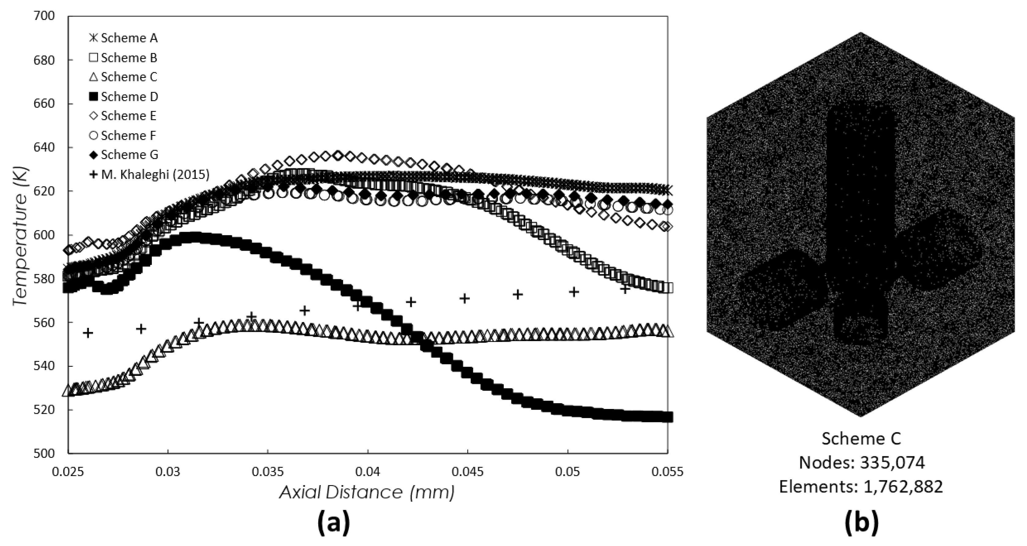
A grid independence test was performed to evaluate the effects of grid sizes on the results, as shown in Figure 2 and the meso-scale combustor channel design is illustrated in Figure 3. Seven sets of meshes were generated using triangular unstructured tetrahedral finite-volume mesh (3D) with SA = 7,176,132 nodes, SB = 3,401,470 nodes, SC = 1,762,882 nodes, SD = 1,161,298 nodes, SE = 796,601 nodes, SF = 598,147 nodes and SG = 479,806 nodes. Laminar flow with counter-flow configuration was considered for this test, where the temperatures of the inlet air as well as the inlet fuel were set to 300 K. Moreover, grid independence was verified by imposing a 1.5% tolerance on key solution metrics mass-averaged outlet temperature, and central recirculation-zone (CRZ) length between mesh SC and the two finer meshes (SA and SB). Within this tolerance, SC reproduced the integral quantities obtained on SA or SB while incurring lower computational cost; consequently, SC was selected for the production simulations. The small residual deviations observed across meshes are ascribed to statistical variability in iterative convergence, with no systematic trend under further refinement, thereby supporting the designation of SC, which consists of 1,762,882 elements, as a grid-independent and cost-efficient discretization for the present study. SC shows the closest results when compared to the previous experimental results [9], as shown in Figure 2. All computational domains included both fluid and solid regions of the meso-scale combustor. All computational tasks were executed on a workstation powered by an Intel Core i9 CPU and 16 GB of memory.

3. Results and Discussion

3.1. Interaction of Vortex Flow and Flame Behavior

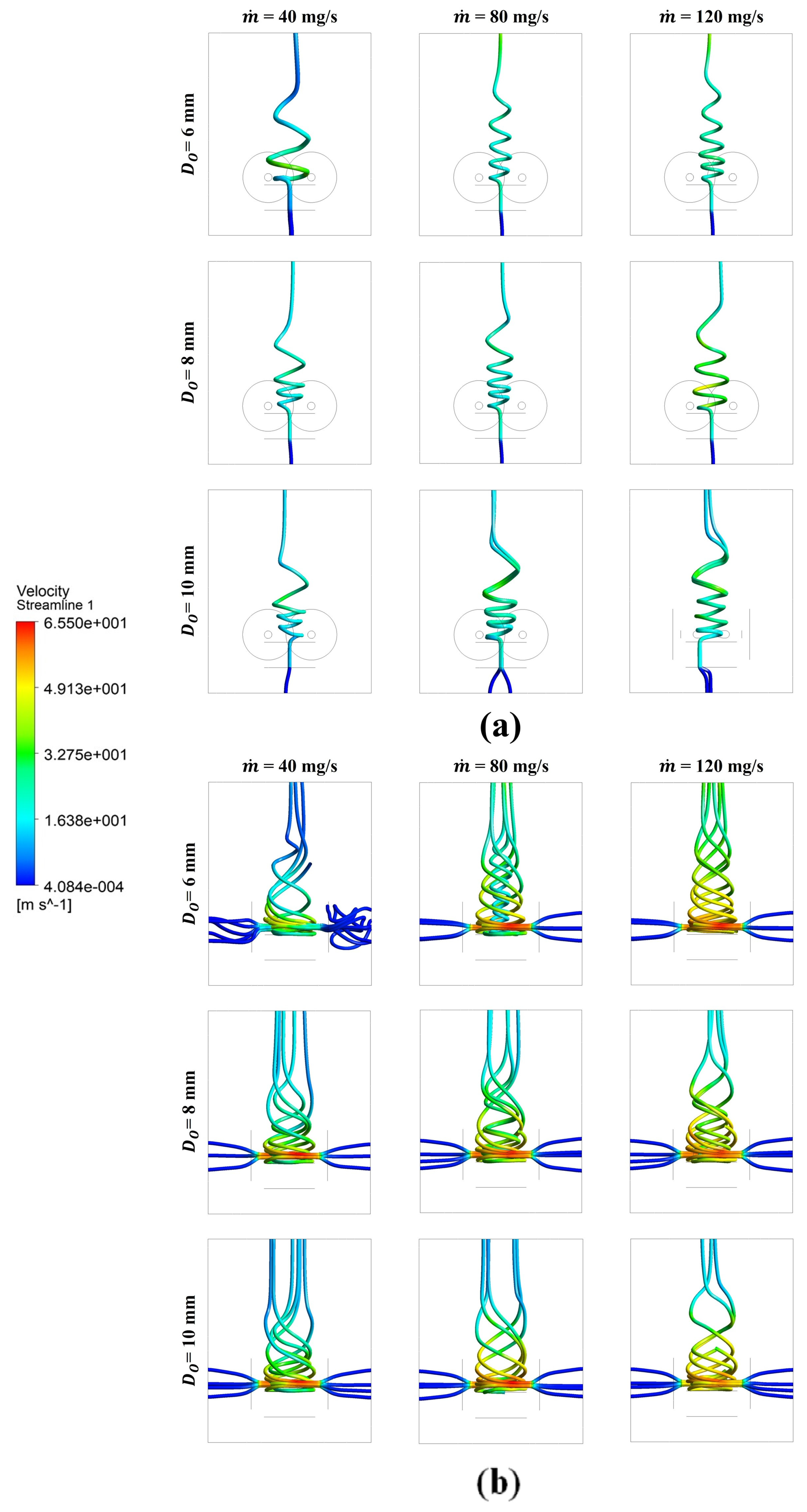
The internal flow dynamics of vortex-stabilized combustors play a critical role in determining combustion performance, flame stability, and heat transfer efficiency. In this study, CFD simulations conducted under stoichiometric natural gas (methane)–air conditions (equivalence ratio φ = 1.0) reveal that outlet diameter significantly influences vortex strength, swirl intensity, and the formation of the central recirculation zone (CRZ). As shown in Figure 4 and Figure 5, decreasing the outlet diameter—particularly the 6 mm configuration—strengthens the central recirculation zone, intensifying reactant mixing, lengthening residence time, and promoting localised flame anchoring. Similar vortex-induced flame holding and mixing enhancement effects in meso-scale combustors have been reported in recent numerical studies [4,14]. This coherent vortex structure has a direct impact on the temperature field within the combustor. Moreover, as shown by the smaller diameter, the 6 mm outlet case produces a sharply defined, high-temperature core reaching approximately 1880 K, concentrated along the combustor centerline. In contrast, larger outlet diameters exhibit more diffused temperature zones and weaker recirculation, indicating less effective combustion confinement. The results highlight a strong coupling between vortex-induced flow structures and heat release distribution, a relationship that is especially critical in meso-scale configurations, where maintaining thermal efficiency in confined volumes is challenging.
In comparison, the 8 mm and 10 mm outlet configurations exhibited visibly weaker central recirculation zones, with the 10 mm case showing a substantially diminished vortex core. This resulted in a shorter flame residence time and poorer flame anchoring, ultimately leading to reduced peak temperatures and broader heat dispersion zones. These geometries generate a less vigorous rotational field and a weaker central recirculation zone, curbing mixing and consequently yielding lower combustion intensity than the 6 mm configuration. Therefore, the findings agree with prior CFD studies on meso-scale combustors: swirl-enhanced central recirculation zones (CRZs) stabilise the flame and focus heat [4,14]. They also show that outlet geometry controls both the flow field and the combustor’s thermal performance, crucial for integrating thermoelectric modules in compact energy systems.

3.2. Combustion Analysis and Interpretation

3.2.1. Swirl-Induced Enhancement in Exhaust and Wall Temperatures

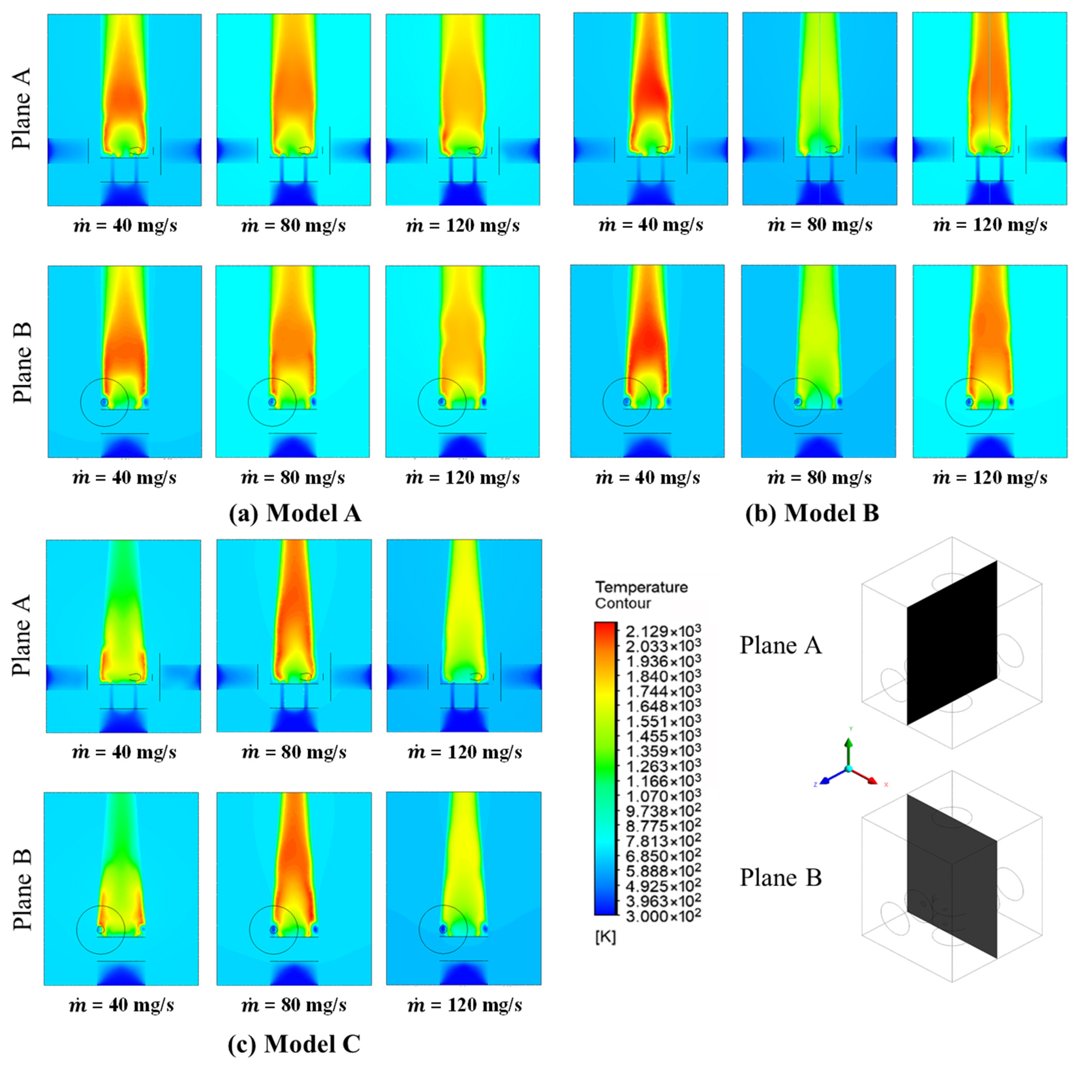
Figure 5, Figure 6 and Figure 7 collectively provide comprehensive temperature behavior images of the meso-combustor’s performance under various outlet configurations. The simulated flow fields, temperature contours, and heat transfer distributions illustrate a direct interdependence between geometric parameters and thermo-fluid behavior. The outlet diameter of a vortex-stabilized meso-combustor plays a pivotal role in regulating exhaust gas temperature and wall heat flux, two critical metrics for thermal efficiency and thermoelectric generator (TEG) integration. As shown in Figure 5, the 6 mm outlet diameter configuration yielded the highest exhaust temperature, reaching approximately 920 K. These results indicate that strengthening the rotational flow and the associated central recirculation enhances mixing and residence time, thereby improving combustion completeness and retaining more thermal energy in the exhaust—beneficial for energy-recovery applications. Wall temperature analysis further corroborates this trend. Figure 5 shows that wall temperatures scale positively with swirl intensity. The 6 mm outlet produced peak wall temperatures of up to 1020 K, particularly near the flame anchoring region. These elevated temperatures are indicative of intensified heat transfer from the combustion core to the combustor structure, a consequence of enhanced flame confinement and recirculation. While beneficial for thermoelectric performance, such thermal loading poses structural challenges in terms of thermal stress and potential material degradation. These findings are consistent with recent numerical studies showing that intensified rotational flow and robust central recirculation promote thermal uniformity in confined combustors [5,15,16]. However, they also highlight the importance of balancing thermal performance with structural integrity, especially in meso-scale systems where high surface-to-volume ratios amplify wall interactions [6].

3.2.2. Flow Field Characterization and Flame Structure Visualization

Particularly when mass flow rates vary, the complex flow dynamics in meso-scale combustors are crucial in determining thermal performance and flame stability. Critical flow features, such as recirculation zones and swirl development, are revealed by computational fluid dynamics (CFD) simulations conducted under stoichiometric conditions. These features have a significant impact on energy transfer mechanisms and flame confinement. By recirculating hot combustion products, these recirculation zones, which are created by flow separation and vortex breakdown, improve flame anchoring and maintain constant ignition in the reaction zone. The high thermal loading close to the flame anchoring region, as shown in Figure 5, emphasizes the close relationship between swirl-induced confinement and localized heat release. This effect is amplified by the intensified vortical structures produced at higher mass flow rates, which improve reactant mixing and lengthen residence times, thereby improving flame stabilization.
Furthermore, as shown in Figure 6, the relationship between flow dynamics and flame structure intensifies with increasing swirl confinement. The increase in wall temperatures indicates that the increased swirl not only increases the thermal load but also facilitates more effective heat transfer to the combustor walls. The increased convective heat flux and improved turbulent mixing brought on by the incoming flow’s greater momentum are responsible for this phenomenon. In response to these changes in flow, the flame structure exhibits a more compact and stabilized reaction zone with less lift-off from flames. Such behavior demonstrates how flow field properties and combustion efficiency are interdependent, with optimal swirl strength ensuring a balance between thermal management and flame stability. In order to design meso-combustors with enhanced performance, especially in applications requiring precise control over temperature distribution and energy conversion efficiency, it is imperative to comprehend these interactions. The knowledge gained from these simulations and visualizations serves as a basis for additional experimental verification and optimization techniques in meso-scale combustion systems.

3.2.3. Flame Shape and Vortex Core Structure

CFD results for the 6 mm outlet configuration reveal a cone-shaped high-temperature flame region, tightly centered along the combustor axis. This design is indicative of strong aerodynamic confinement and efficient heat release. The vortex core surrounding the flame promotes enhanced recirculation and localized heating. Conversely, the 8 mm and 10 mm outlets show more dispersed flame structures with weaker vortex confinement and reduced thermal focus. These broader flame zones suggest diminished flame anchoring and poorer combustion confinement, consistent with the weaker recirculation dynamics predicted for larger outlets. The simulated flame structure supports the mechanism whereby enhanced recirculation fosters robust anchoring; this aligns with numerical evidence that the strength of outlet-induced vortices dictates flame geometry in confined combustors [11].

3.2.4. Flame Stability and CRZ Coupling

Flame stability in meso-combustors is strongly linked to the presence and strength of recirculation zones. Previous researchers [14] demonstrated that increasing swirl intensity through geometric manipulation significantly improves flame anchoring, consistent with the CRZ behavior observed in the current study. The 6 mm configuration consistently exhibits a well-defined CRZ, which reduces local axial velocity, creating a stagnation zone for effective flame holding. This circumstance promotes continuous ignition of unburned reactions and minimizes the risk of flame blowout. The spatial overlap between the CRZ and the high-temperature core (Figure 4) further supports the aerodynamic-thermal coupling. Stronger recirculation enhances both combustion efficiency and thermal localization parameters critical for efficient operation and integration with downstream thermoelectric devices [5,15,16].

3.3. Design Implications for Temperature Distributions

3.3.1. Temperature Profile on Combustor Height

The results offer actionable design guidance for meso-combustors in thermoelectric power systems. Outlet diameter, via its control of recirculation strength and residence time, emerges as a primary geometric lever governing both aerodynamic and thermal performance. The temperature contour (Figure 5) reveals a significant gradient ranging from approximately 300 K to 2129 K, indicating strong thermal stratification within the meso-combustor. Such steep gradients are characteristic of confined combustion systems, where flame anchoring and heat recirculation play crucial roles in sustaining reactions [17]. The high-temperature regions likely correspond to active combustion zones dominated by exothermic reactions, while lower temperatures may signify areas affected by incomplete mixing or convective cooling [18]. The contour spacing further suggests localized variations in heat transfer mechanisms that closely packed lines near the flame zone imply dominant conduction or radiation, whereas wider spacing in cooler regions points to convective heat loss, a well-documented challenge in meso-scale systems due to enhanced wall effects [7]. The temperature gradient along the combustor height emphasises the importance of heat recirculation and thermal boundary layer formation from the standpoint of transport phenomena. The sharp drop in temperature raises the possibility that the combustor height is too low to support full combustion, which could cause the upper sections to quench too soon. This is especially important in meso-combustors because heat dissipation is made worse by the high surface-to-volume ratio [7]. The 1000–1500 K intermediate temperature ranges might be post-flame zones where combustion products cool as a result of heat loss to the environment or mixing with unburned gases. A well-documented challenge in microscale combustion research, such as thermal behaviour, emphasizes the necessity of optimising combustor height to strike a balance between minimising heat losses and maintaining high combustion efficiency [8].
This condition is made more difficult by fluid dynamics since airflow patterns and mixing efficiency are directly impacted by the combustor height. In meso-combustors, recirculation zones, which are frequently required for flame stabilization, are extremely sensitive to the geometrical dimensions of the combustor. According to [19], a shorter height may restrict the growth of these recirculation zones, resulting in localised quenching and insufficient mixing. On the other hand, a height that is too high could decrease the flow velocity, lengthen the residence time, while simultaneously increasing heat losses. The rapid temperature drop suggests that the current configuration may favour the former, according to the temperature contour data. This is consistent with research by [12], which showed that unstable flame fronts and unequal temperature distributions are frequently the result of transitional flow regimes in meso-combustors. When examining temperature behaviour in relation to combustor height, it is impossible to ignore the influence of mass flow rate. The high-temperature zone may be compressed towards the combustor exit by higher mass flow rates, which would lower the effective combustion volume and raise the possibility of blow-off [13]. Reduced mass flow rates may result in wider but colder reaction zones because of extended heat loss, even though they may also improve flame stability. The existing temperature profile points to a middle-ground situation in which flame stability and thermal efficiency are compromised due to incomplete optimisation of the combustor height and mass flow rate. Future research should systematically change both parameters to determine the best operating conditions. In conclusion, the height of the meso-combustor has a significant impact on the temperature behaviour, which in turn affects fluid dynamics, heat transfer, and flame stability. Given that heat loss mechanisms and geometric restrictions predominate in confined spaces, the observed thermal gradient highlights the difficulties in achieving efficient combustion. Applications in micro-propulsion and portable power generation, where maximising combustion efficiency is critical, will require such efforts [20].

3.3.2. Combustor Heat Transfer

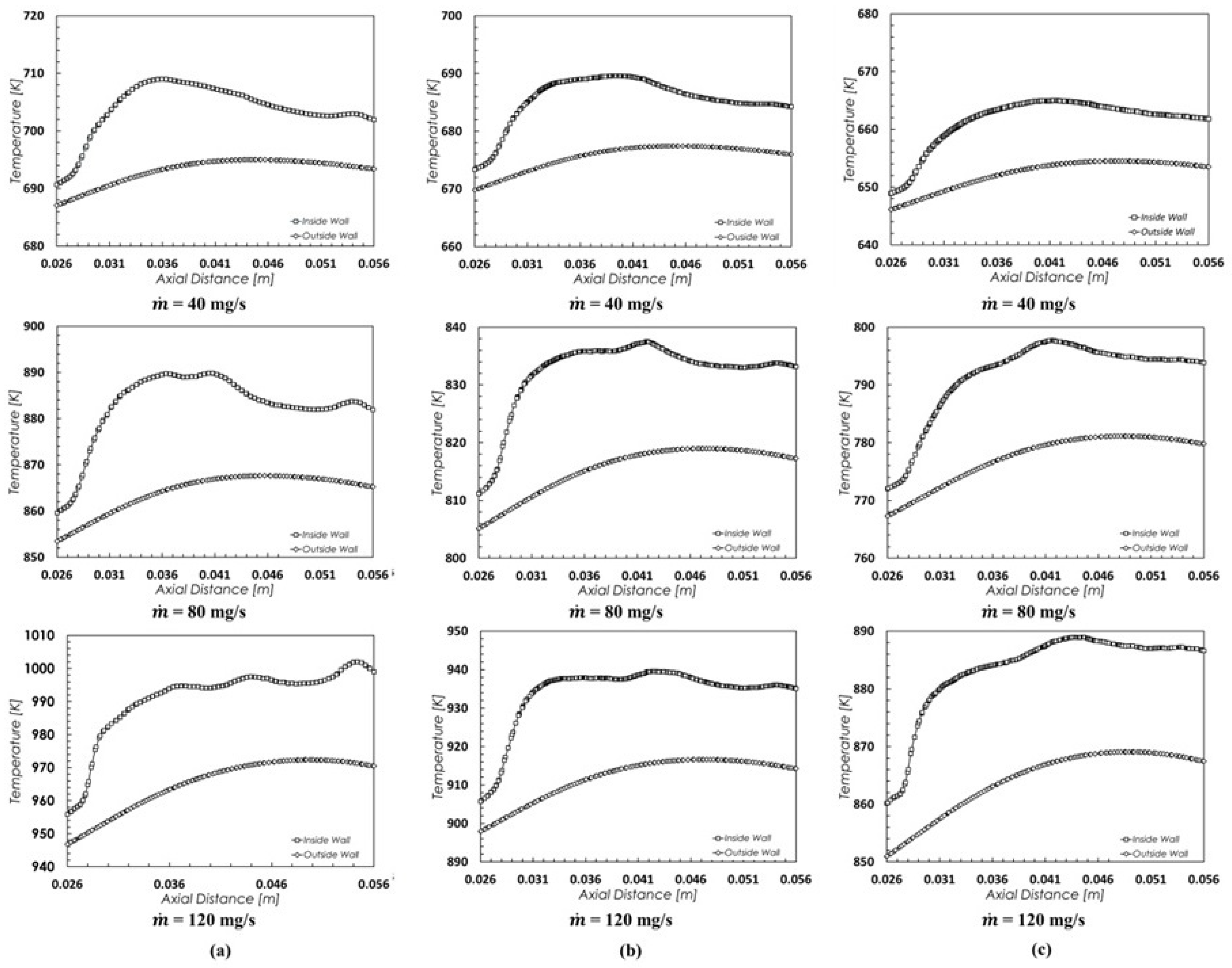
Numerous significant physical and transport phenomena pertaining to the impact of different mass flow rates (ṁ = 40, 80, and 120 mg/s) are revealed by the examination of the temperature distribution at the meso combustor’s inside and outside walls, as shown in Figure 7 (in Section 3.2.1). While the outside wall consistently records lower values by about 20–30 K, the inside wall’s peak temperature stays modest at the lowest mass flow rate of 40 mg/s, ranging between 650 K and 710 K depending on the combustor design (a–c). This suggests that the flame is contained nearer the inner wall area, which could be the result of weak flame anchoring or incomplete combustion. The longer residence time caused by the relatively low momentum at this flow rate is usually advantageous for full combustion, but it can also result in a lower flame temperature if the equivalence ratio is lean or if heat losses predominate. Laminar or transitional regimes provide little convective mixing and insufficient turbulent transport to support high-temperature zones close to the wall surfaces, which is consistent with low Reynolds number flow [21]. Inside wall temperatures rise noticeably as the mass flow rate rises to 80 mg/s, peaking at about 900 K. Because of improved convective heat transfer and a more resilient flame structure, the temperature differential between the interior and exterior walls increases at the same time. The combustor most likely runs at moderate Reynolds numbers in this regime, where mixing is amplified and stronger combustion is supported by transitional to turbulent flows, as shown in Figure 6. Improved flame-holding capacity close to the bluff body or swirl chamber results from an increase in flow momentum, which helps stabilize a recirculation zone, especially in vortex combustors [12].
The thermal behavior is even more pronounced at the maximum mass flow rate of 120 mg/s. Near-stoichiometric or slightly rich combustion conditions, where the chemical reaction rates are at their highest, are indicated by the sharp rise in interior wall temperatures, which approach values of 1010 K. Higher Reynolds numbers are associated with this regime, where convection takes over and heat is swiftly transferred downstream but held close to the wall region by robust recirculation (Figure 7). The outside wall, on the other hand, records temperatures in the range of 950 to 980 K, indicating a delayed but more intense thermal response as more heat is transferred outward. Beyond 0.045 m, the axial temperature gradient likewise flattens, indicating that thermal equilibrium is progressively reached downstream. Swirl-induced flow structures, in which the internal vortex encourages recirculating hot gases, intensify near-wall combustion, and delay flame quenching, have a significant impact on these observations [14]. Due to a stronger central recirculation zone or better bluff body geometry, combustor design (a) shows the highest inside wall temperature at each mass flow rate, suggesting superior flame anchoring and thermal confinement. Design (c), on the other hand, shows a more consistent temperature increase between the interior and exterior walls, which could indicate a wider flame spread and more efficient radial heat transfer.
The interaction of combustor geometry, wall heat transfer coefficients, and local flow dynamics determines how well each design maintains high wall temperatures under various flow conditions. Furthermore, the temperature differential between the inner and outer wall surfaces demonstrates the combustor material’s thermal insulation properties and the changing thickness of the boundary layer across the wall interface. The role of transport phenomena in meso-scale combustor systems is amply demonstrated by the change in wall temperature profiles with increasing mass flow rate. The temperature distribution is influenced by swirl-driven vortex dynamics, recirculation zone structure, and heat transfer through conduction and convection. These results are in line with earlier research that highlighted the importance of thermal feedback, flame stretch, and local fluid dynamics in micro and meso combustion chambers [22,23]. Improving the stability and thermal efficiency of portable energy conversion devices requires an understanding of these interdependencies. One of the most salient insights is the dominant influence of swirl intensity on both flame stabilization and heat release distribution [24]. The 6 mm outlet diameter configuration, by maximizing recirculation and mixing, consistently produced the most favorable thermal profiles and highest exhaust temperatures. This finding aligns with recent studies emphasizing the role of vortex strength in maintaining compact, high-energy-density flame regions in small combustion chambers [3,16]. However, such configurations also induce greater wall thermal loading, as evident in Figure 6, which raises the risk of thermal fatigue and premature material failure. Therefore, future combustor designs should incorporate passive flow control mechanisms such as pre-swirling vanes or helical inserts to maintain swirl performance without reducing outlet diameter excessively.

3.3.3. Exhaust Sensible-Enthalpy Fraction

For a non-premixed, swirl-stabilized meso-combustor, the exhaust sensible-enthalpy fraction ( η s e n ) depends on how the chemical energy of the fuel is partitioned into (i) sensible heat delivered to the walls (useful for TEG/heat-recuperation), (ii) sensible enthalpy carried by the exhaust, (iii) radiative and conductive losses, and (iv) unburned chemical energy. Geometry dependent heat pathways of Model A, B and C the outlet diameter controls swirl intensity and the formation of a central recirculation zone (CRZ), which in turn governs heat localization. The 6 mm outlet (Model C) generates the strongest CRZ and a compact high-temperature core (~1880 K) that enhances both exhaust enthalpy and near-wall heat flux; 8 mm is intermediate; 10 mm shows the weakest CRZ with broader, cooler cores. Consistent with this, Model C yields the highest exhaust temperature (~920 K) and peak wall temperature (~1020 K) near the flame-anchoring region—beneficial for energy recovery but imposing higher thermal stress on structures.
Moreover, due to mass flow rate effects, at low ṁ (≈40 mg s−1), inner-wall temperatures are modest (≈650–710 K), reflecting weaker flame anchoring and larger relative wall losses; outer-wall temperatures trail inner-wall by ~20–30 K due to finite conduction–radiation coupling through the wall. As ṁ increases to ≈ 80 mg s−1, improved mixing and stronger (transitional → turbulent) convection raise inner-wall temperatures (~900 K) and widen the inner–outer wall gradient. At ṁ ≈120 mg s−1, inner-wall temperatures approach ~1010 K and outer-wall ~950–980 K as robust recirculation sustains high near-wall heat release and pushes the system toward downstream thermal equilibrium. The exhaust sensible-enthalpy fraction ( η s e n ) has been calculated as:
η s e n = m ˙ c p T o u t T i n m ˙ f L H V
where m ˙ is the exhaust mass flow rate, c p is the specific heat at constant pressure, T o u t and T r e f = 298 K are the exhaust and inlet gas temperatures, m ˙ f is the fuel mass flow rate, and LHV is the lower heating value of methane (50 MJ/kg).
Exhaust Sensible-Enthalpy Fraction was evaluated using Equation (5) under a consistent set of assumptions (stoichiometric CH4–Air, c p = 1.10 kJ.kg−1.K−1, T i n = 300 K, LHV = 50 MJ/kg, with T o u t estimated from the near-outlet mean of the inner/outer wall temperatures. Across all flow rates, η t h increased monotonically with m ˙ and ranked by outlet diameter as 6 mm > 8 mm > 10 mm. The 6 mm outlet achieved 15.5%, 23.1% and 27.5% at 40, 80, and 120 mg·s−1 respectively; the 8 mm outlet yielded 15.2%, 21.2% and 25.3% and the 10 mm outlet produced 14.7%, 19.2% and 23.0%. The superiority of the 6 mm configuration is consistent with a more coherent recirculation, intensified mixing, longer effective residence time, and tighter temperature confinement, which collectively preserve exhaust enthalpy and elevate wall heat flux attributes favourable for thermoelectric generator integration. Because T o u t was inferred from wall temperatures rather than bulk exhaust gas, these values should be regarded as conservative estimates. These trends align with prior studies [3,5] showing that enhanced recirculation-driven mixing improves thermal conversion efficiency.

4. Conclusions

This study presents a comprehensive CFD-based analysis of vortex-stabilized meso-scale combustors, focusing on the influence of outlet diameter on internal flow structure, flame behavior, and thermal performance. Simulations conducted at stoichiometric conditions (φ = 1.0) for three outlet configurations, 6 mm, 8 mm, and 10 mm, reveal that geometric parameters critically govern the formation of swirl-induced recirculation zones, heat localization, and overall energy retention. The 6 mm outlet diameter exhibited superior aerodynamic and thermal performance, establishing the most coherent and persistent central recirculation zone (CRZ) and a sharply localised high-temperature core. The associated increases in exhaust temperature and wall heat flux indicate strong suitability for thermoelectric generator (TEG) integration. In contrast, the 10 mm configuration displayed weak recirculation and poor thermal confinement, while the 8 mm case offered moderate performance across all metrics. Moreover, wall temperature analysis confirmed that increased swirl intensity correlates with higher surface heating, especially near the anchoring region. While this enhances standard thermal efficiency, it also introduces structural concerns due to elevated thermal stress. These findings highlight the performance trade-offs between combustor geometry and material durability. Overall, this work underscores the necessity of integrated aerodynamic and thermal optimization in the design of meso-scale combustors. The results provide valuable guidance for achieving a balance between flame stability, energy recovery potential, and structural reliability, key considerations for future portable power and energy harvesting applications.

Author Contributions

Conceptualization, M.L.A.L. and C.Y.K.; methodology, M.L.A.L.; software, M.A.R.A.; formal analysis, M.A.-H.M.N.; investigation, M.F.K.; resources, H.J.J.; data curation, M.A.-H.M.N.; writing—original draft preparation, M.A.-H.M.N. and M.A.R.A.; writing—review and editing, C.Y.K.; visualization, A.H.R.; supervision, M.A.-H.M.N.; project administration, C.Y.K.; funding acquisition, M.A.-H.M.N. All authors have read and agreed to the published version of the manuscript.

Funding

The research has been carried out under the Fundamental Research Grant Scheme (FRGS)-Early Career (EC) (FRGSEC/1/2024/TK08/UNIMAP/02/31) provided by the Ministry of Higher Education.

Data Availability Statement

The data presented in this study are available on request from the corresponding author.

Acknowledgments

The authors would like to express their appreciation for all the support received from the Faculty of Mechanical Engineering and Technology, Universiti Malaysia Perlis (UniMAP).

Conflicts of Interest

The authors declare no conflicts of interest.

References

  1. Minotti, A.; Sciubba, E. LES of a Meso Combustion Chamber with a Detailed Chemistry Model: Comparison Between the Flamelet and EDC Models. Energies 2010, 3, 1943–1959. [Google Scholar] [CrossRef]
  2. Sheykhbaglou, S.; Dimitriou, P. Numerical Analysis of Combustion and Thermal Performance of a Bluff-Body and Swirl-Stabilized Micro-Combustor with Premixed NH3/H2/Air Flames. Energies 2025, 18, 780. [Google Scholar] [CrossRef]
  3. Ren, Y.; Wang, Q.; Peng, Y.; Xu, L.; Xia, X.; Qi, F. Strong and weak interactions of a V-shaped premixed swirling flame with outer vortex rings. Combust. Flame 2024, 270, 113760. [Google Scholar] [CrossRef]
  4. Sharifzadeh, R.; Afshari, A. Numerical investigation of flow field effects on fuel–air mixing in a non-reacting trapped vortex combustor with different injection arrangements. Eur. J. Mech. B/Fluids 2020, 82, 106–122. [Google Scholar] [CrossRef]
  5. Tang, C.; Yao, Q.; Jin, W.; Li, J.; Yan, Y.; Yuan, L. Effect of swirler geometry on the outlet temperature profile performance of a model gas turbine combustor. Appl. Therm. Eng. 2025, 260, 124946. [Google Scholar] [CrossRef]
  6. Wu, S.; Laurent, T.D.C.; Abubakar, S.; Li, Y. Thermal performance characteristics of a micro-combustor with swirl rib fueled with premixed hydrogen/air. Int. J. Hydrogen Energy 2021, 46, 36503–36514. [Google Scholar] [CrossRef]
  7. Norton, D.G.; Vlachos, D.G. Combustion characteristics and flame stability at the microscale: A CFD study of premixed methane/air mixtures. Chem. Eng. Sci. 2003, 58, 4871–4882. [Google Scholar] [CrossRef]
  8. Maruta, K. Micro and mesoscale combustion. Proc. Combust. Inst. 2011, 33, 125–150. [Google Scholar] [CrossRef]
  9. Khaleghi, M.; Hosseini, S.E.; Wahid, M.A. Vortex combustion and heat transfer in meso-scale with thermal recuperation. Int. Commun. Heat Mass Transf. 2015, 66, 250–258. [Google Scholar] [CrossRef]
  10. Wan, J.; Zhao, H. Flammability limit of methane-air nonpremixed mixture in a micro preheated combustor with a flame holder. Chem. Eng. Sci. 2020, 227, 115914. [Google Scholar] [CrossRef]
  11. Choi, J.; Rajasegar, R.; Lee, T.; Yoo, J. Development and characterization of swirl-stabilized diffusion mesoscale burner array. Appl. Therm. Eng. 2020, 175, 115373. [Google Scholar] [CrossRef]
  12. Wang, H.Y.; Law, C.K.; Lieuwen, T. Linear response of stretch-affected premixed flames to flow oscillations. Combust. Flame 2009, 156, 889–895. [Google Scholar] [CrossRef]
  13. Tang, A.; Cai, T.; Deng, J.; Xu, Y.; Pan, J. Experimental investigation on combustion characteristics of premixed propane/air in a micro-planar heat recirculation combustor. Energy Convers. Manag. 2017, 152, 65–71. [Google Scholar] [CrossRef]
  14. Palies, P. Flow and Flame Mechanisms for Swirl-Stabilized Combustors. Aerospace 2025, 12, 430. [Google Scholar] [CrossRef]
  15. Zhou, T.; Zhao, K.; Li, F.; Wang, K.; Meng, N.; Wang, D. Effects of swirl numbers on the unsteady characteristics of pilot flame in a triple-swirler staged combustor. Case Stud. Therm. Eng. 2023, 44, 102846. [Google Scholar] [CrossRef]
  16. Wang, K.; Li, F.; Zhou, T.; Wang, D. Numerical simulations on the effect of swirler installation angle on outlet temperature distribution in gas turbine combustors. Appl. Therm. Eng. 2024, 240, 122252. [Google Scholar] [CrossRef]
  17. Ju, Y.; Maruta, K. Microscale combustion: Technology development and fundamental research. Prog. Energy Combust. Sci. 2011, 37, 669–715. [Google Scholar] [CrossRef]
  18. Fernández-Tarrazo, E.; Sanchez, A.; Linan, A.; Williams, F. A simple one-step chemistry model for partially premixed hydrocarbon combustion. Combust. Flame 2006, 147, 32–38. [Google Scholar] [CrossRef]
  19. Ehsan, R.; Masoud, D. Extending the Navier–Stokes solutions to transition regime in two-dimensional micro- and nanochannel flows using information preservation scheme. Phys. Fluids 2009, 21, 082001. [Google Scholar]
  20. Yetter, R.A.; Risha, G.A.; Son, S.F. Metal particle combustion and nanotechnology. Proc. Combust. Inst. 2009, 32, 1819–1838. [Google Scholar] [CrossRef]
  21. Turns, S.R. An Introduction to Combustion: Concepts and Applications, 2nd ed.; McGraw-Hill Education: Singapore, 2000. [Google Scholar]
  22. Choi, M.; Choi, K.W.; Muhammad, H.A.; Lee, Y.D. Experimental investigation of combustion characteristics of a CH4/O2 premixed flame: Effect of swirl intensity on flame structure, flame stability, and emissions. Case Stud. Therm. Eng. 2012, 55, 104069. [Google Scholar] [CrossRef]
  23. Tan, Y.; Jiaqiang, E.; Chen, J.; Liao, G.; Zhang, F.; Li, J. Investigation on combustion characteristics and thermal performance of a three rearward-step structure micro combustor fueled by premixed hydrogen/air. Renew. Energy 2022, 186, 486–504. [Google Scholar] [CrossRef]
  24. Sudarsanan, S.; Mohammad, A.; Selvaraj, P.; Juhany, K.A.; Alsulami, R.A.; Kumar, S.; Velamati, R.K. A state-of-the-art micro-mixing micro-combustor with enhanced flame stabilization characteristics using H2-air mixtures. Energy Convers. Manag. X 2025, 26, 101001. [Google Scholar] [CrossRef]
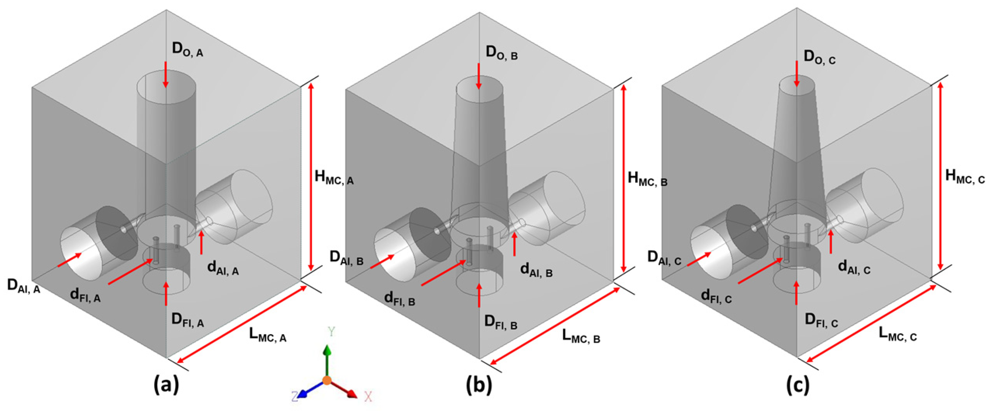
Figure 1. Configuration of meso-scale combustor channel; (a) Model A, Do,A = 10 mm, (b) Model B, Do,B = 8 mm, and (c) Model C, Do,C = 6 mm.
Modelling 06 00094 g001
Figure 2. Meso-scale combustors: (a) meshing with their respective schemes [9] and (b) meshing scheme C.
Modelling 06 00094 g002
Figure 3. Meso-scale combustor CAD views (Model A, Do,A = 10 mm): (a) boundary conditions, (b) isometric view, (c) right view and (d) front view.
Modelling 06 00094 g003
Figure 4. Pathlines at different fuel flow rates at stoichiometric conditions (a) of the fuel inlet and (b) air inlet.
Modelling 06 00094 g004
Figure 5. Examples of high-temperature core formation and thermal confinement across orthogonal planes. (a) Model A, Do,A = 10 mm, (b) Model B, Do,B = 8 mm, and (c) Model C, Do,C = 6 mm under stoichiometric conditions (φ = 1.0).
Modelling 06 00094 g005
Figure 6. Temperature distribution along combustor height for Models A to C. (a) Model A, Do,A = 10 mm, (b) Model B, Do,B = 8 mm, and (c) Model C, Do,C = 6 mm under stoichiometric conditions (φ = 1.0).
Modelling 06 00094 g006
Figure 7. Axial wall-temperature profiles (inner vs. outer walls) for Models A–C at (a) Model A, Do,A = 10 mm, (b) Model B, Do,B = 8 mm, and (c) Model C, Do,C = 6 mm under stoichiometric conditions (φ = 1.0).
Modelling 06 00094 g007
Table 1. Boundary condition settings (adapted from [9]).
ModelSettings
Viscous modelK-epsilon (2 Equations) RNG, with swirl-dominated flow option
Radiation modelDiscrete ordinate (DO)
Reaction modelModel of turbulence chemistry with volumetric species
transport reaction and eddy dissipation
Boundary conditionsAir inletMass Flow Rate: Various
Temperature: 300 K
Concentration:
O2 = 23%, N2 = 77%
Fuel inletMass Flow Rate: Various
Table 2. Geometric dimensions of meso-scale vortex combustors (mm).
SamplesModel AModel BModel C
Length of meso chamber, LMC32
Height of meso chamber, HMC40
Diameter outlet, DO1086
Diameter air inlet, DAI10
Diameter fuel inlet, DFI10
Diameter air inlet, dAI1.5
Diameter fuel inlet, dFI1
Height fuel inlet 1, HFI, 15
Height fuel inlet 2, HFI, 25
Center air inlet, CAI13.83
Center meso-chamber, CMC19.42
Height chamber, HC30
Disclaimer/Publisher’s Note: The statements, opinions and data contained in all publications are solely those of the individual author(s) and contributor(s) and not of MDPI and/or the editor(s). MDPI and/or the editor(s) disclaim responsibility for any injury to people or property resulting from any ideas, methods, instructions or products referred to in the content.