Abstract
One of the most well-known problems of dynamics is the “ladder problem”. In this paper, a theoretical model is proposed followed by the experimental validation of the predicted solution. The model refers to a rod of negligible thickness with the ends leaning frictionless on two walls. By approximating the rod as a segment, the problem is simplified, and the Lagrange equations can be applied. The experimental validation of the model had to address several challenges: the actual rod–wall contacts are singular points, friction cannot be neglected, and the rod’s motion must remain confined to the vertical plane. The physical “ladder” was designed as a cylindrical rod with two identical balls of well-controlled geometry, fixed at the ends. These spheres make contact with two half-cylinder grooves—one vertical and one horizontal—ensuring that the motion remains parallel to the vertical plane. The presence of dry friction in the sphere–groove contacts leads to a complex, strongly nonlinear differential equation of motion, requiring numerical methods of integration. A test-rig was designed and constructed for the experimental study of motion, and an aspect overlooked by the theoretical model was emphasised: the interruption of contact with the vertical wall. An excellent agreement was found between the experimental data and the theoretical results.
1. Introduction
1.1. The Ladder Problem
One of the primary objectives in system dynamics is to determine how the system’s positional parameters evolve over time, as well as the manner in which the interactions among its components vary [1]. This is not an easy task since these time-variation laws are derived from the system’s equations of motion, which are typically differential equations with a strong nonlinear character, often necessitating numerical integration methods [2,3]. Furthermore, the presence of dry friction [4,5,6,7] in the pairs of the studied system may lead to a strong dependency of the evolution of the system [8,9,10,11,12] on it, as a function of the initial conditions eventually leading to chaotic behaviour [13]. Two contrasting scenarios can be encountered when modelling the evolution of a dynamic system. In the first scenario, the actual system is available, and based on it, accepting the simplifying hypothesis, the theoretical model is created. In the second scenario, a theoretical model is proposed, which must ultimately be validated using an experimental device. In both scenarios, the experimental model will provide a set of discrete points corresponding to the sought-after dependencies. When the transition from the theoretical/actual model to the actual/theoretical is accomplished adequately, the experimental points will be placed on the variation curves obtained applying the theoretical models. A well-known theoretical model presented in the monographs of dynamic systems is the “ladder problem’’ and this paper aims to validate this model by an experimental device.
1.2. Obtaining the Equation of Motion of the Classical Model
The “ladder problem” [14,15,16,17,18,19,20] consists in finding the motion of a linear homogenous segment of mass and length , whose ends are in contact with two walls, a horizontal and a vertical one, as illustrated in Figure 1.
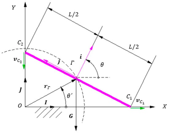
Figure 1.
Rectilinear ladder leaning against a vertical wall and the horizontal ground (velocity vectors in green, unit vectors of mobile system in purple).
The ladder contacts the two walls in the points and . The only external force considered is the weight . In this case, it is assumed that the supports in the points and are ideal (without friction). It should be noted that the literature presents various variants of the problem—some include an additional force (such as the weight of a person) alongside the weight , or consider friction at the supports, which transforms the problem into a statics one. Next, we consider the situation when the only external force is the weight of the ladder applied in the middle of it, the point , and the supports are frictionless. Under these hypotheses, the weight causes the ladder to move such that point shifts to the right and point downward, and thus the rotation of the ladder has a trigonometric direction. Additionally, the centre of the rod moves along a circle centred at the origin with a radius . The segment is the median in the right triangle . From the Median Theorem, in the right triangle, the median is half of the hypotenuse . But since , the length of is constant and the centre of mass of the ladder moves on a circle of centre and radius /2. Since the system has one degree of freedom (1DOF) [21], it is possible to choose the polar angle of the position vector of the centre of mass as the parameter describing the rod’s position. For reasons to be explained later, the position parameter of the ladder is chosen as the angle between the normal to the ladder , with the horizontal direction. From simple geometrical considerations, it is shown that
Due to the absence of friction in the rod’s supports, the simplest method for determining the beam’s motion is to use Lagrange’s equations of the second kind. In order to apply Lagrange’s equations, the hypothesis to be considered is that the reactions from the pairs do not produce mechanical work (they are ideal reactions, normal to the contacting surfaces). For this reason, the reactions do not occur in the Lagrange equations of second kind and the work is produced only by the applied external force (here, the only applied external force is the weight of the ladder G). If it is desired that other forces besides G are to be considered, the method can be applied but, previously, all forces should be reduced to a resultant force and a resultant torque, applied in the same point of the ladder:
where is the kinetical energy of the system, and , are the coordinates and the generalised coordinates, respectively, and are the generalised forces given by
where are the forces applied to the system and are the corresponding vectors of position. We denoted by p the degree of freedom (DOF) of the system. In this case, as long as both contacts are maintained, the system is mono-mobile and . The generalised coordinate is the angle and the generalised velocity is . The kinetical energy of the rod is the sum between of translational energy of the centre of mass and the rotational energy with respect to the centre of mass. The centre of mass has the position vector, with respect to the fixed coordinate system of versors I, J, K:
The velocity of the centre of mass is
The kinetical energy of the ladder is
where the central axial moment of inertia is found with the relation
Next, the required derivatives are calculated:
With concern for the generalised forces, since (the unique force is the weight ), deriving Relation (4) with respect to results in
Considering that
the generalised force can be found:
The differential equation of the motion of the ladder has the final form
1.3. Numerical Solution of the Classical Model
The nonlinear Equation (13) is solved numerically using the Runge–Kutta algorithm. In Figure 2, the solutions are shown: the angle θ and its time derivative, the angular velocity (denoted θ1).
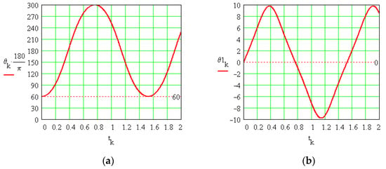
Figure 2.
Solutions of the equation of motion of the ladder: (a) the angle of position; (b) the angular velocity. The dotted red lines correspond to initial conditions.
From Figure 2, the rod has an oscillatory motion. This behaviour would be valid if the constraints at the points and were bilateral, allowing the ladder to maintain continuous contact with the walls. However, in the case of unilateral constraints, it is expected that the contact with the vertical wall will be lost. The contact between the spherical end of the ladder and the wall can be realised in two ways: by force (unilateral contact) or by construction (bilateral contact)—by introducing the sphere into a channel of width theoretically equal to the diameter of the sphere. The bilateral contact ensures the position of the centre of the sphere permanently on the axis of symmetry of the groove while the unilateral contact ensures a constant distance (radius) to the wall as long as towards the wall a compression force is ensured.
In the present paper, we consider the finite dimensions of the ladder and the contacts between the ladder and the walls are modelled as sphere–plane contact. We came to this conclusion after comparing the scans of the edge–plane contact and the sphere–plane contact. Accepting for the actual ladder the model consisting in two spheres connected by a cylindrical rod, it is possible to model a ladder with an eccentric centre of mass. For the adopted dynamical model and for stipulated values of the coefficients of friction from the two contacts, the equation of motion is deduced and as are the relations for the normal reactions from the two contacts. These relations permit finding the moment when the interruption of the contact with the vertical wall happens.
2. Material and Method
Verifying the theoretical model with an experimental device presents the following challenges:
- -
- The friction between the rod and the walls cannot be neglected in the actual model;
- -
- The actual rod has a certain cross-section, and the contact between the rod and the wall occurs along its edge;
- -
- The difficulty in ensuring the plane-parallel motion of the rod in the vertical plane.
Regarding the friction between the rod and the walls, it cannot be eliminated by any means and is, therefore, included in the modelling. Here we have some remarks concerning the type of contact, and we compare two cases of ladder end–wall contacts: circular edge–plane and sphere–plane. These rod-ends are presented in Figure 3a,b, namely a circular cylinder and a sphere, detailed in Figure 3c,d. The microtopography of the contact regions obtained via laser scan profilometry is shown in Figure 3e,f. This highlights the fact that for the actual contact, the circular edge–wall contact presents more important discontinuities than the sphere–wall contact.
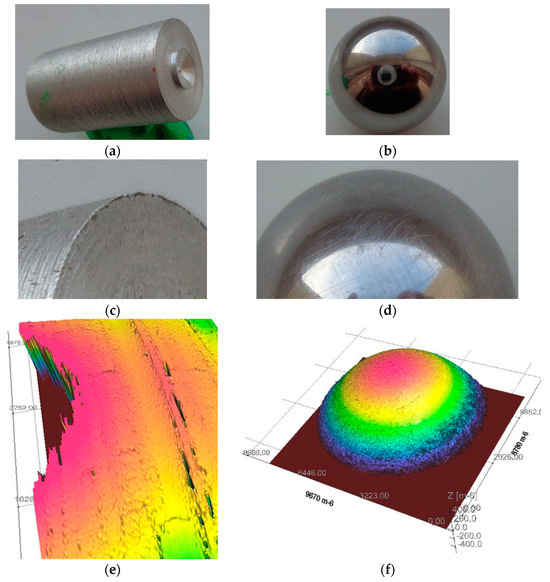
Figure 3.
Two alternatives of the wall–ladder contact: (a) contact on the circular edge of the ladder; (b) contact on spherical end of the ladder; (c) detail of the circular edge; (d) detail of spherical surface; (e) laser scan of microtopography of circular edge; (f) laser scan of microtopography of sphere end. The rainbow scale is used by the software for vertical displacement.
For the other two issues, the following solutions are proposed: to avoid the edge–plane contact between the end of the rod and wall, the experimental ladder was designed as a cylindrical rod with two balls (with precisely controlled geometry) fixed at its ends. For containing the motion of the ladder to the vertical plane, two solutions were considered: placing the spheres from the ends of the model in two grooves, one vertical and the other horizontal, each having either a semi-cylindrical or a V-shaped groove, as shown in Figure 4.
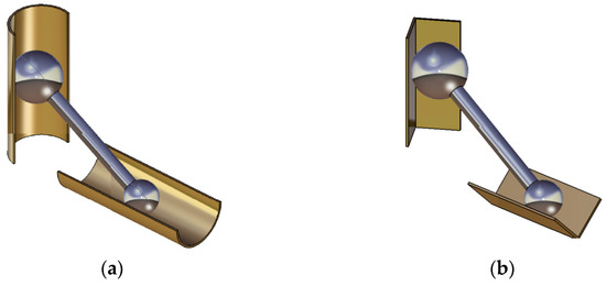
Figure 4.
Solutions for supporting the ends of the rod for ensuring the motion in the vertical plane: (a) sphere—semi-cylindrical groove contact; (b) sphere—V-shaped groove contact.
Amid the two proposed solutions form Figure 4, the first option was chosen because it ensures two points of contact. In the second option, each end makes two points of contact with the V-shaped groove; therefore, to ensure the position of the ladder in the vertical plane, these points of contact must be arranged symmetrically relative to the plane of motion—a requirement that poses construction challenges. Moreover, the locations of the normal reactions and friction forces depend on the angle between the faces of the groove, making it difficult to ensure that the groove faces are symmetrically positioned about the theoretical vertical plane of motion. The spherical ends of the moving body and the presence of dry friction result in a far more complex differential equation of motion, endowing it with a strongly nonlinear character that necessitates the use of numerical integration methods [22].
2.1. Dynamical Analysis Using Dynamic Simulation Software
In order to validate the obtained numerical solution, an experimental device was designed and constructed in the laboratory to capture the actual motion of the system. An aspect that the theoretical model had overlooked—the loss of contact between the rod and the vertical wall—was observed. Replacing the edge–surface contact with sphere–plane or sphere–groove contact, along with the inclusion of the sphere–wall frictions effects [23], considerably complicates the study of the dynamic model. To gain insights into the system’s behaviour under these conditions, a simulation was performed, using the MSC.ADAMS 2013 Release software. As shown in Figure 5, mobile body 1, which represents the ladder and is modelled as a cylindrical rod with two spherical ends, contacts the walls (2), in the points and 4, respectively. In these two contacts, the Coulomb friction is implemented, characterised by the coefficient of static friction and the coefficient of dynamic friction . The ideal planar pair 5, between the ground and the mobile body, ensures that the motion remains confined to the vertical plane.
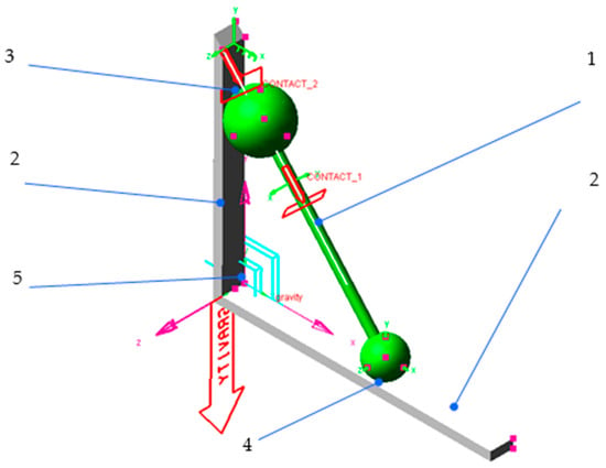
Figure 5.
The dynamic system modelled using the MSC.ADAMS software: 1—mobile body; 2—leaning walls; 3, 4—sphere–plane contacts; 5—planar joint.
In order to characterise the friction at contacts 3 and 4, [24,25], two situations were considered, based on the values of the static and dynamic friction coefficients. In the first case, the behaviour was studied with the values and , while for the second case, the values and were used. Four scenarios were simulated: (a) both contacts without friction; (b) friction occurs only at the lower contact; (c) friction occurs only at the upper contact; (d) friction is present at both contacts.
In the table of legends attached to each of Figure 6, Figure 7 and Figure 8, there are specified the values of the static coefficient of friction and dynamic coefficient of friction, separated by the underline “_”. The first set of two values corresponds to the contact between the body and the horizontal plane and the second set of values after the sign “:” corresponds to the contact body–vertical plane.
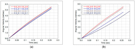
Figure 6.
Variation in angular velocity, for two sets of coefficients of friction: (a) ; , (b) ; .
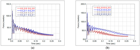
Figure 7.
Variation in the normal reaction N1: (a) ; ; (b) ; .
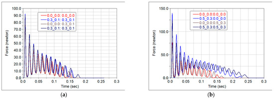
Figure 8.
Variation in the normal reaction N2: (a) ; ; (b) ; .
For each of the above scenarios and for both sets of friction coefficient values, the variations in the following parameters are presented: the angular velocity of the ladder, Figure 6; the normal reaction from lower contact, Figure 7; the normal reaction from the upper contact, Figure 8. The values from the legends in Figure 5, Figure 6 and Figure 7 indicate the values of the friction coefficients for the lower contact followed by those from the upper contact. It can be observed that, for small friction forces, the angular velocity of the body does not change significantly, Figure 6a. As the friction forces increase, their effect becomes more apparent, according to Figure 6b. Concerning the effect of friction on the normal reactions at both contacts, higher friction leads to increased reaction forces, as shown in Figure 7b and Figure 8b. Figure 8a,b show that, regardless the of friction force values, the normal reaction eventually vanishes and this fact attests to the detachment of the ladder from the vertical wall.
An unexpected phenomenon, which we cannot explain, is the periodical increase and decrease in the values of the two normal reactions and . This phenomenon occurs both with or without friction, as shown in Figure 7 and Figure 8. This observation is at odds with the system’s kinematic characteristics, represented here by the smooth variation in the angular velocity from Figure 6.
2.2. Analytical Solution of the Proposed Model
As mentioned above, the numerical solution for the system’s motion—when contact is made with both walls—results in oscillatory normal reactions that do not accurately reflect physical reality. Even recent papers [26,27,28,29,30,31] accept the ladder modelled as a segment. In ref. [32], the theoretical results obtained for the simplified model are validated by experiments.
To clarify the contradictions between numerical simulation and the analytical solution of the simplified model, we now present the analytical solution for the motion of the body that substitutes the ladder. The geometry of the replacing body, two spheres joined through a cylindrical rod, is shown in Figure 9. All three components of the body are made from the same material, of density .
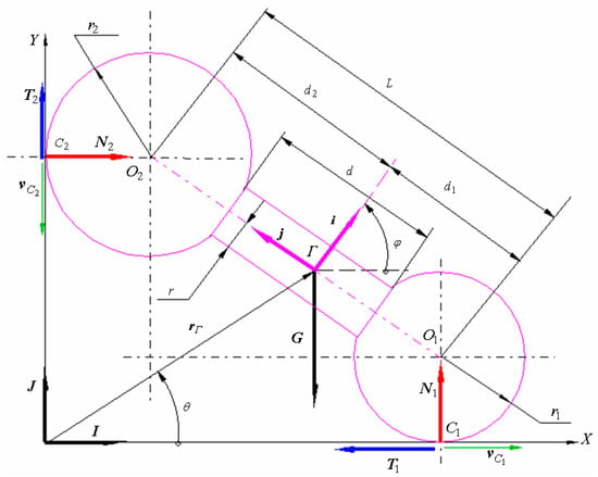
Figure 9.
Schematic for the calculus of analytical model (applied force—black; velocities—green; normal reactions—red; friction forces—blue).
Figure 9 shows that the two walls define the axes of the fixed reference frame of versors , , and ; the two balls which are in contact with the walls, of centres and ; moves along a horizontal straight line, with its position specified by the parameter , while moves along a vertical straight line, with its position dictated by the parameter . In the general case, the centre of mass of the mobile body lies on the axis of rotation, between the centres and , and describes an ellipse in the fixed reference frame with its centre at the point , the artifice applied when the ladder is modelled as a segment—where the rotation of the ladder is described by the polar angle of the radius vector of the centre of mass —cannot be applied here, since a more complex relationship exists between this angle and the actual rotation angle of the ladder. To define the orientation of the mobile body, a mobile coordinate system s, shown in Figure 9, is attached to the body. This coordinate system uses unit vectors: which is normal to the rod; which is aligned along the cylindrical rod from towards ; and finally, . The complete geometry of the body is defined by the radii of the spheres and , the distance between the centres of the spheres , and the radius of the cylindrical connecting rod . According to the physical model, the radius of the cylinder is much smaller than the radii of the spheres, and , which allows us to express the following relation:
Based on the above relation, one can approximate that the mobile body is composed of two complete spheres of radii , and the cylinder of radius and length . Accepting the hypothesis that the motion is confined to the vertical plane, the external forces applied to the body are its weight acting in the centre of mass , and the reactions from the contact points and . In each contact point, a normal reaction, and and a corresponding friction force, and , occur, with the friction forces opposing the relative velocity between the wall and the ladder. Assuming that the body rotates in the counterclockwise (trigonometric) direction during its motion, the relative velocities and and implicitly, the friction forces and , are oriented as shown in Figure 9. Assuming dry friction between the walls and the spheres, the magnitudes of the friction forces will be proportional to the normal reactions:
where are the coefficients of dynamic friction between the spheres and the walls. The unknowns of the problem are the position parameter of the system represented by the angle and the two normal reactions and . In order to find these reactions, the theorem of momentum is applied—specifically, the centre of mass motion theorem, as well as the angular momentum theorem with respect to the centre of mass [33,34]. For applying these theorems, the inertial characteristics of the body must be known, that is, the mass , the position of the centre of mass , and the moment of inertia about a central axis normal to the plane of motion. The body is composed of three simple elements: two spheres of masses , and a cylindrical rod of mass :
where is the length of the rod, found using the Relation (14). The total mass of the body is
Due to the symmetry of revolution of the mobile body, the centre of mass will be positioned on the axis of revolution. The position will be stipulated using the distance from it to the centre of a sphere. For instance, the position of the centre of mass with respect to the point will be found writing the equality between the static moments with respect to for the entire body, and for the three bodies, respectively.
From here, it results in
In order to find the moment of inertia , the central moments of inertia of the three constituent components, calculated with respect to their corresponding central axes perpendicular to the plane of motion, are calculated. For spheres and for the cylindrical rod
Then, the Steiner theorem is applied with respect to the centre of mass of the body:
The acceleration of the centre of mass is needed, so the condition of closure for the vector contour is written, considering the centres of the two balls stipulated by the coordinates and respectively.
The versors from Equation (22) are expressed by
With Relation (23) replaced in Relation (22), the following is obtained:
And Relation (24) are used for finding the coordinate of the centre of mass :
As anticipated, Equation (25) contains parametric equations of an ellipse with the centre in the point and of semi-axes and . The second derivatives with respect to time of Relation (25) represent the projections of the acceleration of the centre of mass on the axes of the immobile system:
The theorem of motion of the centre of mass is written as follows:
where
The function is the signum function, defined as [35]
and and are the velocities of the contact points and alongside the axes and , respectively. To find them, the derivatives with respect to time of the Relation (24) are calculated:
In the evaluation of the signum of the two velocities, the scalar can be eliminated and therefore the concrete form of Equation (27) becomes
Since the system performs a plane-parallel motion, the moment of momentum theorem has projection only by the axis:
where are the position vectors of the contact points with respect to the centre of mass , having the following expressions:
By replacing in Relation (33) the Expression (23) of the versors, and considering Equations (28) and (31), Equation (32) becomes
Matrix Equations (32) and (34) provide three scalar equations that form the linear system of unknowns , , and given below:
The solutions of the system are
where
From system (36), we note that the position of the mobile body is stipulated using an ordinary differential equation of second order. This equation has a strongly nonlinear character and solving it requires the use of a numerical algorithm. In this case, the Runge–Kutta IV with constant step was applied. The Mathcad program [36] was used for integration, which has implemented a subroutine allowing for the numerical integration of ordinary differential equations. The initial conditions must be stipulated for a differential equation of second order:
Condition (39) physically represent the initial position and initial angular velocity. However, since the launch always starts from rest, the initial conditions take the following form:
The geometrical and inertial characteristics of the mobile body—the mass and the central principal moments of inertia, obtained analytically—are shown in Figure 10a, while the corresponding values obtained using the simulation software are shown in Figure 10b.
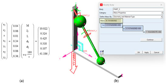
Figure 10.
Geometric and inertial characteristics of the mobile body: (a) deduced analytically; (b) found using dynamic simulation software (model of mobile body—green; force—red arrow; planar joint—cyan; fixed system of coordinate—magenta).
Figure 11 presents the analytical results for the time variation in the rotation angle , and the angular velocity , for two tribological situations. It can be noticed that the angle (that stipulates the position of the mobile body) increases from an initial value to a final value, corresponding to the time . In Figure 12, the variations in the normal reactions and . These plots correspond to two values of the coefficient of dynamic friction: (a) and (b) . The moment when detachment between the body and the vertical wall occurs is denoted , found from the condition . Beyond this moment, the relations obtained from system (36) are no longer valid. For time values greater than , the relations are given in [37]. Figure 13 illustrates the variation in the magnitudes of the normal reactions and for the same friction coefficient values.
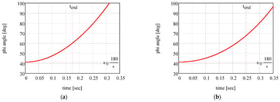
Figure 11.
The variation in the angle of rotation of the mobile body, for (a) , (b) . (horizontal dotted lines are markers for initial values of angles and vertical dotted lines are markers for the detachment moment).
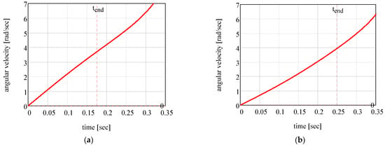
Figure 12.
The variation in the angular velocity of the mobile body for (a) ; (b) . The vertical dotted lines are markers for the detachment moment.
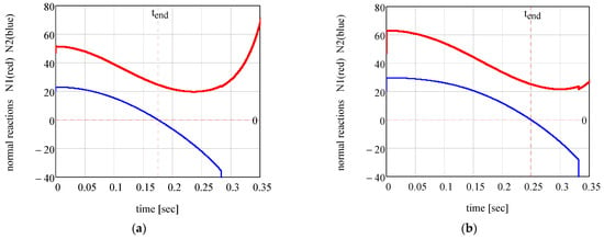
Figure 13.
The variation in normal reactions —red line, and —blue line, for (a) ; (b) . The vertical red dotted lines are markers for detachment moment.
From the above figure, it can be noted that the variation in the angular velocity obtained analytically is similar to that provided by simulation (black plots from Figure 6), although the analytical values are somewhat lower than those from the simulation.
Concerning the variation in the magnitudes of the normal reactions and from Figure 13, they appear different from the ones from Figure 7 and Figure 8. One might infer that the simulation plots could represent curves similar to the analytical ones, but with an additional oscillatory damped component superposed.
3. Results and Discussions
The results obtained from numerical and analytical modelling were presented for the mobile body consisting in two balls connected by a cylindrical rod. When the body is supported by two walls, a horizontal and a vertical one, this model can be the generalisation of the ladder problem presented in the introductory section. More precisely, the ladder problem represents a limiting case of the body with two spheres connected by a rod, when all the radii, of the spheres and cylinder, tend to zero. The two models, numerical and analytical, yield nearly identical results concerning the motion of the mobile body, as evidenced by the comparison between Figure 6 and Figure 12. However, there are notable differences in the normal reactions at the contact points between the spheres and the walls, with the plots in Figure 7 and Figure 8 differing significantly from those in Figure 13. One can observe that all the kinematical parameters—position, angular velocity, angular acceleration, obtained either numerically or analytically—exhibit smooth time variations over the interval up to the detachment of vertical contact, as seen in Figure 12. Moreover, analytical Relation (36) for the calculus of normal reactions depend not only on these kinematical parameters but also on a set of constants: the dimensional characteristics , the coefficients of dynamic friction , gravitational acceleration , the mass of the body . This dependence suggests that the time evolution of the normal reactions should also be smooth, as shown in Figure 13, which contradicts the irregular features observed in Figure 7 and Figure 8. To address this discrepancy, an experimental device was constructed. The construction is simple, as shown in Figure 14a.
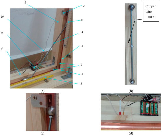
Figure 14.
The experimental device: (a) assembly, (b) detail of the mobile body, (c) stopper for the initial position of the upper contact, (d) d.c. source and diodes.
The walls that confine the body’s motion to the vertical plane are shown in Figure 14a. The half-cylinder grooves (1) were made from copper pipe, diameter , split axially. The two grooves were fixed on the two sides of the timber frame (3), with the parallelepipedal parts (3). The mobile body (4), detailed in Figure 14b, was made of two identical steel balls, of diameter . Threaded holes were made by electro-erosion in the balls. The threaded rod ,, was the connecting element between the balls, secured by two screw-nuts. After assembly, the distance between the centres of the balls was . To track the position of the mobile body, two scales (5 and 6), graduated in millimetres, were attached to each of the parts (3). A stopper (7) (detail in Figure 14c) was mounted on the vertical arm of the frame to ensure that the mobile body was always launched from the same initial position, corresponding to an angle . Two critical moments needed to be recorded: first, the start of the motion, and second, the instant when the upper contact disconnected. To identify these moments, two electrical circuits were implemented. The mobile body (4), the copper wires (10), a d.c. source (9), and the two diodes (8) were the elements of these circuits (detail in Figure 14c) and the circuit schematics are presented in Figure 15. In each circuit, the mobile body made a contact, either with the stopper (7), or with the vertical groove. To ensure that the motion of the body was not appreciably influenced by the wiring, a single copper wire , diameter , was used for all the circuit connections. According to Figure 15, with the body in launching position, both circuits were closed and the LEDs and were on. After the start of motion, the contact between the upper ball and the stopper opened and the LED was off. The LED remained on until the moment , when the mechanical contact between the upper ball and the vertical groove was disrupted.
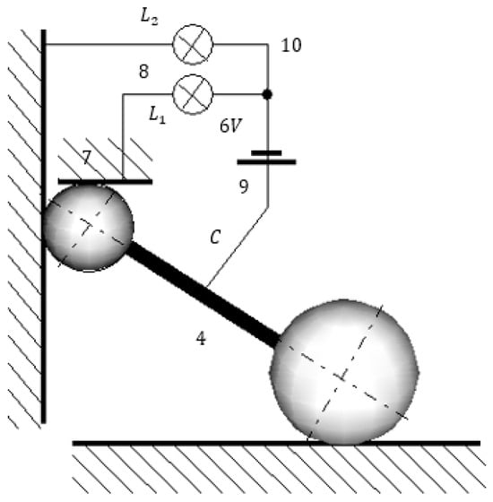
Figure 15.
Electrical circuits for detecting the start of motion and the upper contact interruption.
For the experimental study of the mobile body, a non-contact body method was chosen, because the use of any sensor [38] placed on the mobile body could affect the inertial characteristics of the sensor-body assembly and implicitly, the motion. Additionally, the presence of the sensor could produce the displacement of the centre of mass from the axis of revolution of the body, potentially transforming the motion from plane-parallel to a spatial one—a scenario that would be more challenging to model. The first non-contact method intended involved an ultrasound displacement sensor [39]. This method presents the advantages of providing a precise dependency of the displacement versus time but the major drawback is the impossibility of establishing the start and final moments (when the detachment from the wall occurs). Ultimately, the selected method involves video recording the horizontal motion of the lower ball using a camera operating at . The recorded video is then split into individual frames using specialised software, and by analysing these frames, a numerical dependency is obtained, where is the time instant and is the position of the centre of the lower ball, red on the horizontal scale. The methodology of finding the position of the lower ball’s centre is shown in Figure 16. A still frame (4596F) from the experiment is shown in Figure 16a, and in Figure 16b, a circle enveloping the ball is placed on the trace, the axes of the circle define the centre, and the value of the displacement is identified on the ruler.
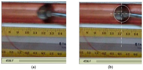
Figure 16.
Finding the position of the centre of lower ball at a given time: (a) video frame capture; (b) superimposing the contour trace of the ball on the image.
The moment when the contact between the upper ball and the stopper is disrupted is identified as shown in Figure 17. Two successive images (time lag ) of the two diodes are shown. In Figure 17a, the intensity of light is higher than the one from Figure 17b, the circuit being interrupted in the latter. Obviously, due to thermal inerty, diode is not off instantaneously, but the difference in brightness is enough to identify the moment when the contact is disrupted. A similar procedure is applied for identifing the moment when the mechanical contact between the vertical groove and the ball is interrupted.
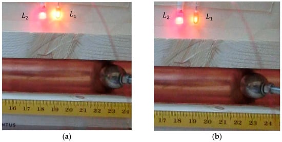
Figure 17.
Identifying the moment when the contact between the stopper and the upper ball is interrupted: (a) initial; (b) after .
Numerous launchings were made from the same initial position. The results for two such launchings are presented in Table 1.

Table 1.
Experimental data for two launchings (set 1 and set 2).
The experimental data are used for establishing the dependency with the following relations:
Two mentions must be made concerning Relation (41): first, the term is a constructive characteristic of the device and represents the abscissa of the lower ball’s centre in the coordinate system at the moment of motion initiation, and in this case, ; second, the minus sign (−) occurs because the displacement of the lower ball’s centre is in the direction of decreasing the parameter .
In order to corroborate the experimental results obtained using Relation (41) with the results of the proposed theoretical model, the inertial characteristics and of the mobile body and the coefficient of friction between the ball and the groove are required. Regarding the inertial characteristics, both balls and the rod are made from steel, density . For the geometry specified by , ; , the analytical results obtained from the relations in Section 2.2 are presented in Figure 18a, while the results from numerical analysis, using the modelling in the CATIA.Dassault-Assembly module [40], are shown in Figure 18b. An excellent agreement between analytical and numerical results is evident.
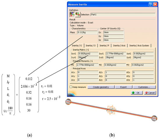
Figure 18.
Finding the inertial characteristics of the mobile body; (a) analytically; (b) using the CATIA.Dassault V5R17 software.
In order to find the coefficient of friction, specialised literature may be referred to [41], but a direct experimental finding is preferred [42]. For this purpose, the mobile body is positioned such that both balls are in contact with the horizontal groove. Then the entire device is gradually tilted by rotating it about the common edge of its sides, using the slow displacement of a mobile cylinder, Figure 19, until the moment when the body starts sliding along the groove. The trigonometric tangent of the tilting angle reached when the motion starts provides the value of the coefficient of friction. In this case, (while in the literature, for the cast iron–copper pair of materials, the value is ) was obtained.
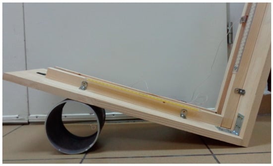
Figure 19.
Experimental set-up for finding the coefficient of sliding friction between the ball and the groove.
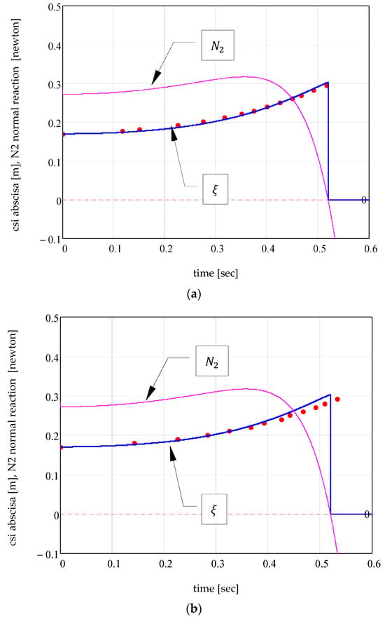
Figure 20 compares the analytical and experimental results for the displacement of the centre of the lower ball, for the two data sets from Table 1, and also the plot of variation in the normal reaction , in order to highlight the moments of detachment from the vertical wall. Very good concordance between the experimental data (red points) and analytical results (blue plot), which validated the proposed theoretical model, can be seen.
Concerning the disagreement between the numerical and theoretical results, we cannot provide a reasoned explanation. We can only assume that these discrepancies occur due to the adopted friction models. For the theoretical model, we adopted the simplest dry friction model (Amontons–Coulomb), while the MSC.ADAMS software uses the dynamic LuGre model [43]. Marques [6] compares the theoretical results obtained for the translational displacement of a small body, connected to the ground via a linear spring, placed on a horizontal rough belt moving with constant velocity. There are considered to be two models of instantaneous friction (Amontons–Coulomb and Bengisu–Akay) and two models of friction with memory (Dahl and LuGre). After the four equations of motion were integrated, four completely different evolutions were obtained, but it could not be specified which of these models better corresponds to reality. To support this affirmation, we can cite Schuderer [44]: “The simplest model provided by these mbs packages is a piecewise defined regularisation between friction regimes. A standard regularisation approximates stiction behavior by slow joint creep. To achieve long-term stiction, mbs package specific friction models are provided. These models switch between stick and slip. Each algorithm uses relative velocity to distinguish between different states to maintain long-term stick”…“Adams also offers the LuGre model as a dynamic friction model. However, as illustrated in [43] this model exhibits severe drawbacks”.
The model presented in the present paper is a generalised problem for the ladder: it studies the motion of a body composed of two balls connected by a cylindrical rod. Similar to other approaches from the literature for the dynamic problem (moving ladder), under the hypothesis of dry friction between the balls and the walls, the following are completed:
- Deduction of the nonlinear differential equation of motion;
- The numerical integration of the equation of motion for the specified initial conditions;
- Finding the expressions of the normal reactions from the two sphere–wall contacts;
- Finding the time when the vertical contact disrupts, imposing the condition of cancelled reaction from the vertical wall, the instant that corresponds to the transition from a 1DOF system into a 2DOF system;
- The design and construction of a device used for experimental validation of the analytical solutions;
- The numerical simulation of the motion of the system using a software gave results in disagreement with the physical reality.
We highlight that the main theoretical achievement of this paper is the fact that we propose a model for the ladder problem, which also models the contacts between the ends of the ladder and the walls with sphere–groove contacts (where the end effects are not present and of well-controlled geometry), different from other models where the edge–plane contacts are considered. The proposed theoretical model was also experimentally validated.
The proposed theoretical model also permits, by changing the dimensions (radii of the end-spheres, dimensions of the connecting rod), the controlled variation in the inertial characteristics of the body (mass, position of the centre of mass, inertia matrix). The generalised shape of the mobile body and the experimental device and methodology are useful tools for the validation of a theoretical friction model.
4. Conclusions
This paper aims to experimentally validate the theoretical solution for one of the most well-known problems in dynamics: the ladder problem. The theoretical model refers to a rod of negligible thickness with the ends leaning frictionless on two walls, one vertical and the other horizontal. Approximating the rod to a segment simplifies the problem since the trajectory of the rod’s centre of mass is a circle, and the polar angle of its position vector can be considered as a generalised coordinate required for the application of the Lagrange equations.
The experimental validation of the theoretical model must overcome several challenges. The actual rod has a tangible thickness and thus, the rod–wall contact is formed in a singular point at the end of the rod. For the actual model, the friction with the walls cannot be neglected, and maintaining the moving rod within the vertical plane also presents a difficulty.
To address these issues, the experimental “ladder” was designed as a cylindrical rod with two identical balls of well-controlled geometry, fixed at its ends. These spheres contact two half-cylinder grooves—one vertical and one horizontal—ensuring that the motion remains confined to the vertical plane. The spherical shape of the ends of the mobile body and the presence of dry friction lead to a complex, strongly nonlinear differential equation of motion that requires numerical integration. Additionally, the compound geometry of the mobile body permits variation in the geometric parameters (balls radii and dimensions of connecting cylindrical rod) and therefore the inertial characteristics (mass, position of the centre of mass, axial moment of inertia) can be modified. For this generalised model, assuming dry friction (as majority of studies consider in the literature) between the balls and the walls for the moving ladder (dynamic problem), an analysis was performed.
A laboratory device was designed and constructed to capture the system’s experimental motion, revealing an aspect disregarded by the theoretical model: the interruption of the contact with the vertical wall. Notably, an excellent agreement was found between the experimental data and the theoretical results.
Author Contributions
Conceptualisation, S.A. and C.B.; methodology, S.A. and C.L.; software, S.A. and I.-C.R.; validation, C.L., D.-A.C. and I.-C.R.; investigation, I.-C.R. and C.L.; writing—original draft preparation, S.A. and F.-C.C.; writing—review and editing, F.-C.C., C.L. and D.-A.C.; supervision, F.-C.C. and C.B. All authors have read and agreed to the published version of the manuscript.
Funding
This research received no external funding.
Data Availability Statement
All data underlying the results are available as part of the article and no additional source data are required.
Conflicts of Interest
The authors declare no conflicts of interest.
References
- Ardema, M.D. Review of Newtonian Dynamics. In Analytical Dynamics: Theory and Applications, 1st ed.; Ardema, M.D., Ed.; Springer: New York, NY, USA, 2004; Volume 1, pp. 1–45. [Google Scholar]
- Butcher, J.C. Numerical Methods for Ordinary Differential Equations, 2nd ed.; John Wiley & Sons: Chichester, UK, 2008; pp. 93–104. [Google Scholar]
- Armanini, C.; Dal Corso, F.; Misseroni, D.; Bigoni, D. Configurational forces and nonlinear structural dynamics. J. Mech. Phys. Solids 2019, 130, 82–100. [Google Scholar] [CrossRef]
- Popova, E.; Popov, V. The research works of Coulomb and Amontons and generalized laws of friction. Friction 2015, 3, 183–190. [Google Scholar] [CrossRef]
- Coulomb, C.A. Théorie des Machines Simples, en Ayant Égard au Frottement de Leurs Parties, et à la Roideur des Cordages; Bachelier, Libraire: Paris, France, 1821; pp. 212–245. [Google Scholar]
- Marques, F.; Flores, P.; Claro, J.C.; Lankarani, H. A survey and comparison of several friction force models for dynamic analysis of multibody mechanical systems. Nonlinear Dyn. 2016, 86, 1407–1443. [Google Scholar]
- Marques, F.; Flores, P.; Claro, J.C.P.; Lankarani, H.M. Modeling and analysis of friction including rolling effects in multibody dynamics: A review. Multibody Syst. Dyn. 2019, 45, 223–244. [Google Scholar]
- Bengisu, M.T.; Akay, A. Stability of friction-induced vibrations in multi-degree-of-freedom systems. J. Sound Vibr. 1994, 171, 557–570. [Google Scholar]
- Dahl, P.R. Solid friction damping in mechanical vibrations. AIAA J. 1976, 14, 1675–1682. [Google Scholar]
- Dahl, P.R. A Solid Friction Model; Technical Report; The Aerospace Corporation: El Segundo, CA, USA, 1968; pp. 12–17. [Google Scholar]
- Pennestrì, E.; Valentini, P.P.; Vita, L. Multibody dynamics simulation of planar linkages with Dahl friction. Multibody Syst. Dyn. 2007, 17, 321–347. [Google Scholar] [CrossRef]
- Armstrong-Hélouvry, B.; Dupont, P.; de Wit Canudas, C. A survey of models, analysis tools and compensation methods for the control of machines with friction. Automatica 1994, 30, 1083–1138. [Google Scholar] [CrossRef]
- Alaci, S.; Alexandru, C.; Ciornei, F.-C.; Doroftei, I.; Irimescu, L. Chaos illustrations in dynamics of mechanisms. In New Trends in Mechanism and Machine Science; Mechanisms and Machine Science; Springer: Cham, Switzerland, 2020; Volume 89, pp. 297–304. [Google Scholar] [CrossRef]
- Available online: https://www.laddersukdirect.co.uk/latest-news/?tag=history+of+ladders (accessed on 10 January 2025).
- Available online: https://www.rcet.org.in/uploads/academics/regulation2021/rohini_14042492967.pdf (accessed on 12 January 2025).
- Available online: https://physique.merici.ca/mechanics/chap13mech.pdf (accessed on 8 January 2025).
- Mendelson, K.S. Statics of a ladder leaning against a rough wall. Am. J. Phys. 1995, 63, 148–150. [Google Scholar] [CrossRef]
- Glane, S. Combining dynamics and numerics using the falling ladder problem. Eur. J. Phys. 2019, 40, 055001. [Google Scholar] [CrossRef]
- Silverman, M. Reaction Forces on a Fixed Ladder in Static Equilibrium: Analysis and Definitive Experimental Test of the Ladder Problem. World J. Mech. 2018, 8, 311–342. [Google Scholar] [CrossRef]
- The Static Ladder Problem with Two Sources of Friction. Available online: https://wikis.mit.edu/confluence/display/RELATE/The+Ladder+Problem (accessed on 15 January 2025).
- Davidson, J.K.; Hunt, K.H. Robots and Screw Theory: Applications of Kinematics and Statics to Robotics, 1st ed.; Oxford University Press: New York, NY, USA, 2004; pp. 134–191. [Google Scholar]
- Atkinson, K.; Han, W.; Stewart, D. Numerical Solution of Ordinary Differential Equations; John Wiley & Sons: Hoboken, NJ, USA, 2009; pp. 67–94. [Google Scholar]
- Greenwood, J.; Tripp, J. Contact of two nominally flat rough surfaces. Proc. Inst. Mech. Eng. 1970, 185, 625–633. [Google Scholar]
- Giesbers, J. Contact Mechanics in MSC Adams—A Technical Evaluation of the Contact Models in Multibody Dynamics Software MSC Adams. Bachelor’s Thesis, University Twente, Enschede, The Netherland, 2012; pp. 13–19. [Google Scholar]
- Flores, P.; Lankarani, H.M. Contact Force Models for Multibody Dynamics; Solid Mechanics and Its Applications Series; Springer International Publishing: Cham, Switzerland, 2016; Volume 226, p. 171. [Google Scholar]
- Ghorashi, M. New insights on the falling ladder problem. Meccanica 2022, 57, 2281–2292. [Google Scholar] [CrossRef]
- Glane, S.; Müller, W.H. The sliding ladder problem revisited in phase space. Am. J. Phys. 2019, 87, 444–448. [Google Scholar]
- Kapranidis, S.; Koo, R. Variations of the sliding ladder problem. Coll. Math. J. 2008, 39, 374–379. [Google Scholar]
- Silverman, M. The Role of Friction in the Static Equilibrium of a Fixed Ladder: Theoretical Analysis and Experimental Test. World J. Mech. 2018, 8, 445–463. [Google Scholar] [CrossRef]
- Salu, Y. Revisiting the ladder on a wall problem. Phys. Teach. 2011, 49, 289–290. [Google Scholar]
- González, A.G.; Gratton, J. Reaction forces on a ladder leaning against a rough wall. Am. J. Phys. 1996, 64, 1001–1005. [Google Scholar]
- Oliveira, J.B.; Carvalho, P.S.; Mota, M.F.; Quintas, M.J. Dynamics of a sliding ladder leaning against a wall. Phys. Educ. 2015, 50, 329–334. [Google Scholar]
- Ardema, M.D. Newton-Euler Dynamics; Springer: New York, NY, USA, 2006; pp. 231–260. ISBN 978-0-387-23276-8. [Google Scholar]
- Mangeron, D.; Irimiciuc, N. Mecanica Rigidelor cu Aplicaţii în Inginerie; Editura Tehnică: Bucureşti, Romania, 1978; Volume I, pp. 304–319. (In Romanian) [Google Scholar]
- Venetis, J. An Explicit Form of Signum Function. Mathematics 2024, 12, 3246. [Google Scholar] [CrossRef]
- Maxfield, B. Engineering with Mathcad; Elsevier Linacre House: Oxford, UK, 2006; pp. 317–335. [Google Scholar]
- Alaci, S.; Ciornei, F.-C.; Lupascu, C.; Romanu, I.-C. Mathematical Model of the Evolution of a Simple Dynamic System with Dry Friction. Axioms 2024, 13, 372. [Google Scholar] [CrossRef]
- Eren, H. 193 Specialty Displacement and Angle Sensors. In Handbook of Measuring System Design; Sydenham, P.H., Thorn, R., Eds.; Part 13, Section 2. Displacement and Angle Measurement; John Wiley & Sons: Hoboken, NJ, USA, 2005; Volume 3. [Google Scholar]
- Wei, Y. Applications of Ultrasonic Sensors: A Review. Appl. Comp. Eng. 2024, 99, 144–148. [Google Scholar] [CrossRef]
- Zamani, N.; Weaver, G.M. CATIA V5 Tutorials Mechanism Design & Animation, 1st ed.; SDC Publications: Mission, KS, USA, 2012. [Google Scholar]
- Arnoux, J.J.; Sutter, G.; List, G.; Molinari, A. Friction experiments for dynamical coefficient measurement. Adv. Tribol. 2011, 2011, 613581. [Google Scholar] [CrossRef]
- Marino, L.; Cicirello, A. Experimental investigation of a single-degree-of-freedom system with Coulomb friction. Nonlinear Dyn. 2020, 99, 1781–1799. [Google Scholar] [CrossRef]
- Rill, G.; Schaeffer, T.; Schuderer, M. LuGre or not LuGre. Multibody Syst. Dyn. 2023, 60, 191–218. [Google Scholar] [CrossRef]
- Schuderer, M.; Rill, G.; Schaeffer, T.; Carsten, S. Friction modeling from a practical point of view. Multibody Syst. Dyn. 2024, 63, 141–158. [Google Scholar] [CrossRef]
Disclaimer/Publisher’s Note: The statements, opinions and data contained in all publications are solely those of the individual author(s) and contributor(s) and not of MDPI and/or the editor(s). MDPI and/or the editor(s) disclaim responsibility for any injury to people or property resulting from any ideas, methods, instructions or products referred to in the content. |
© 2025 by the authors. Licensee MDPI, Basel, Switzerland. This article is an open access article distributed under the terms and conditions of the Creative Commons Attribution (CC BY) license (https://creativecommons.org/licenses/by/4.0/).