Abstract
Organ-on-a-chip technology is a 3D cell culture breakthrough of the last decade. This rapidly developing field of bioengineering intertwined with microfluidics provides new insights into disease development and preclinical drug screening. So far, optical and fluorescence microscopy are the most widely used methods to monitor and extract information from these models. Meanwhile transmission electron microscopy (TEM), despite its wide use for the characterization of nanomaterials and biological samples, remains unexplored in this area. In our work we propose a TEM sample preparation method, that allows to process a microfluidic chip without its prior deconstruction, into TEM-compatible specimens. We demonstrated preparation of tumor blood vessel-on-a-chip model and consecutive steps to preserve the endothelial cells lining microfluidic channel, for the chip’s further transformation into ultrathin sections. This approach allowed us to obtain cross-sections of the microchannel with cells cultured inside, and to observe cell adaptation to the channel geometry, as well as the characteristic for endothelial cells tight junctions. The proposed sample preparation method facilitates the electron microscopy ultrastructural characterization of biological samples cultured in organ-on-a-chip device.
1. Introduction
In the last 20 years we have witnessed an expansion of 3D cell culture models in the form of organ-on-a-chip (OoC) platforms that have revolutionized in vitro studies [1,2]. OoCs are an alternative tool in preclinical research to address the challenges in the development of new medicines, arising as a response to limited availability of human models, especially in the area of disease target identification, drug efficacy and toxicity studies [3,4].
OoCs are devices with one or more biocompatible microfluidic chambers, allowing the growth and maintenance of 3D cell culture under sterile and controlled conditions. A microfluidic channel can be perfused with media to exert shear stress or to supply nutrients, drugs, nanoparticles, immune cells, bacteria or viruses to the cell culture. The chip design permits other manipulations, like mechanical or electrical stimulation as well as modifications of cell microenvironment [4,5,6,7,8]. The flexibility in design and operations makes microfluidic chips suitable to mimic broad range of physiological conditions in healthy organs or to induce disease pathology at a tissue level [9,10,11,12]. The OoC technology has a major impact in cancer research (cancer-on-a-chip), where different elements of the tumor microenvironment can be recreated and used for drug screening or for revealing the development of the disease [3,4,13]. An important focus is placed on cancer vasculature, where its abnormal growth and morphology leads to enhanced permeability, that currently is the fundamental phenomenon used in design of drug nanocarriers to ensure their extravasation [14,15,16,17].
The field of biology research rapidly adapted the OoC microfabrication technique based on photolithography and soft lithography procedures, involving the use of polydimethylsiloxane (PDMS). PDMS is the bioengineering gold standard for the fabrication of microfluidic chips, offering tens of nanometers in microstructure resolution. It is biocompatible, permeable to gasses, optically transparent, flexible, and relatively easy and cost-efficient in fabrication. PDMS allows for rapid prototyping, adjustable body thickness, incorporation of special elements such as built-in electrodes, and microchannel surface can be modified from hydrophobic to hydrophilic, what makes it a very appealing material for the OoC technology [18,19].
The field of organ-on-a-chip is still quite young, therefore, new cell analysis and environment monitoring methods are constantly developing. A majority of OoCs are reliant upon fluorescence microscopy as a method for information retrieval [20,21,22]. Fluorescence microscopy is an accessible method that offers dynamic and real-time monitoring of the “live” environment with the use of labelling molecules, however it cannot reveal all the interesting details. The imaging can be performed to a depth ranging from tens to a few hundred micrometers, depending on the optical properties and the sample’s nature, however the achievable resolution decreases significantly with the image depth. Furthermore, labelling molecules are specific for individual cell or matrix components, which limits the amount of 3D geometry information that can be retrieved from an image [23,24,25].
There are several alternative methods, complementary to microscopy, to support the real-time monitoring of the OoC environment. Often, they require an integration of new elements such as electrodes into the chip design [26,27,28,29]. One of the methods, well-established in 2D cell culture, is transepithelial electrical resistance (TEER). TEER is used to measure the integrity of the epithelial barrier, and has been applied to gut- and lung-on-a-chip models, to reveal the viability of the systems, as well as barrier disruptions [5,30]. Methods integrating new elements into chips are heavily dependent on the chip design and fabrication, as the distance or localization of the sensing parts impacts the readout and makes the comparison among individual research groups difficult [31].
The transmission electron microscopy (TEM) technique is widely used in the characterization of nanomaterials and biological specimens thanks to its high resolution [32,33,34]. It provides not only ultrastructural cell characterization, but also detailed spatial information about the studied microenvironment [35,36]. Nevertheless, it remains largely unexplored in the field of OoCs, for two main reasons: there are no readily-available methods and the sample preparation is invasive and requires multiple steps.
In this work we present the preparation of a PDMS-based 3D cell culture chip, suitable for post-processing and imaging with transmission electron microscopy. We prepared a model of tumor blood vessel-on-a-chip inspired by the abnormal vasculature geometry [37] and performed necessary steps to obtain ultrathin samples, compatible with TEM technique. We imaged cross sections of human umbilical vein endothelial cells (HUVECs) adhering and adapting to the geometry of the chip channel. Electron microscopy provided very high resolution and allowed us to observe particular elements of the cells, including endothelium-specific tight junctions [37,38,39].
2. Materials and Methods
2.1. Fabrication of the Serpentine Chip
2.1.1. Photolithography
The chip layout, comprising a serpentine 200 μm wide microchannel (Figure S1) and fabricated in an acetate photomask using CAD/Art Services (outputcity.com (accessed on 10 September 2021)) was designed in AutoCAD software (Autodesk, San Rafael, CA, USA). The mask was used to prepare a master mold in the lithography process. Briefly a glass substrate (microscope glass slide 25 × 75 mm, Corning, (Glendale, AZ, USA) was washed with purified water and soap, flushed with EtOH, dried on a hotplate, and treated with oxygen plasma (Expanded Plasma Cleaner PDC-002, Harrick Scientific Corporation, Pleasantville, NY, USA). A negative SU-8 2050 photoresist (MicroChem, Round Rock, TX, USA) was deposited on the glass slide surface using 2-step spin coating (WS-650MZ-23NPP/LITE, Laurell Technologies Corporation, North Wales, PA, USA) to obtain a 50 μm-thick layer (following the instructions attached to the SU-8 photoresist): 10 s at 500 rpm acceleration of 500 rpm/s and 30 s at 3000 rpm and acceleration 1500 rpm/s. The deposition was followed by a 2-step soft bake (2 min at 65 °C, 7 min at 95 °C). To perform the photoresist polymerization the mask was placed on the top of the deposited layer, introduced into the UV-photolithography mask aligner (MJB4, SUSS Microtec, Garching, Germany) and exposed to 17.2 mW/cm2 UV-light for 9.3 s. After UV irradiation the sample was post-baked for 2 min at 65 °C and 7 min at 95 °C. The unpolymerized photoresist was washed away with SU-8 developer (MicroChem) and the master mold dried and silanized with trichlorosilane (Sigma-Aldrich, Saint Louis, MO, USA). The appearance of microstructures was examined using interferometer (Wyko NT1100, Veeco Instruments, Plainview, NY, USA).
2.1.2. Soft Lithography
PDMS replicas were prepared by soft lithography molding. Elastomer and curing agent (Sylgard 184, Dow CorningMidland, MI, USA) were weighed intp a plastic cup (in a ratio of 10:1, wt:wt) thoroughly mixed, degassed and poured over the master mold placed in a Petri dish. The dish with PDMS was left on flat surface for 24 h at RT and then placed into an oven at 60 °C for 3 h. Cured PDMS replica was peeled off, cut out and 1.0 mm holes punched out in the inlets/outlet of the serpentine. The PDMS replica was bound to thin layer of PDMS (100 μm) to enclose the microchannel with prior surface plasma activation for 30 s. Finally, the sample was put in the oven to promote bonding between the layers.
Thin layer of PDMS was prepared by single step spin-coating of the elastomer and curing agent mixture (10:1, wt:wt) on a 140 mm Petri dish. The process was set to 60 s at 2000 rpms with the acceleration of 500 rpm/s. The obtained thin PDMS layer was cured in an oven during 3 h at 60 °C. In our protocol, we decided to apply thin PDMS layer as the chip bottom (instead of typically used coverslip glass) to be able to process the entire chip without its prior deconstruction as well as to avoid separation of the layers, that can occur if a glass bottom is used.
2.2. Preparation of Tumor Blood Vessel-on-a-Chip
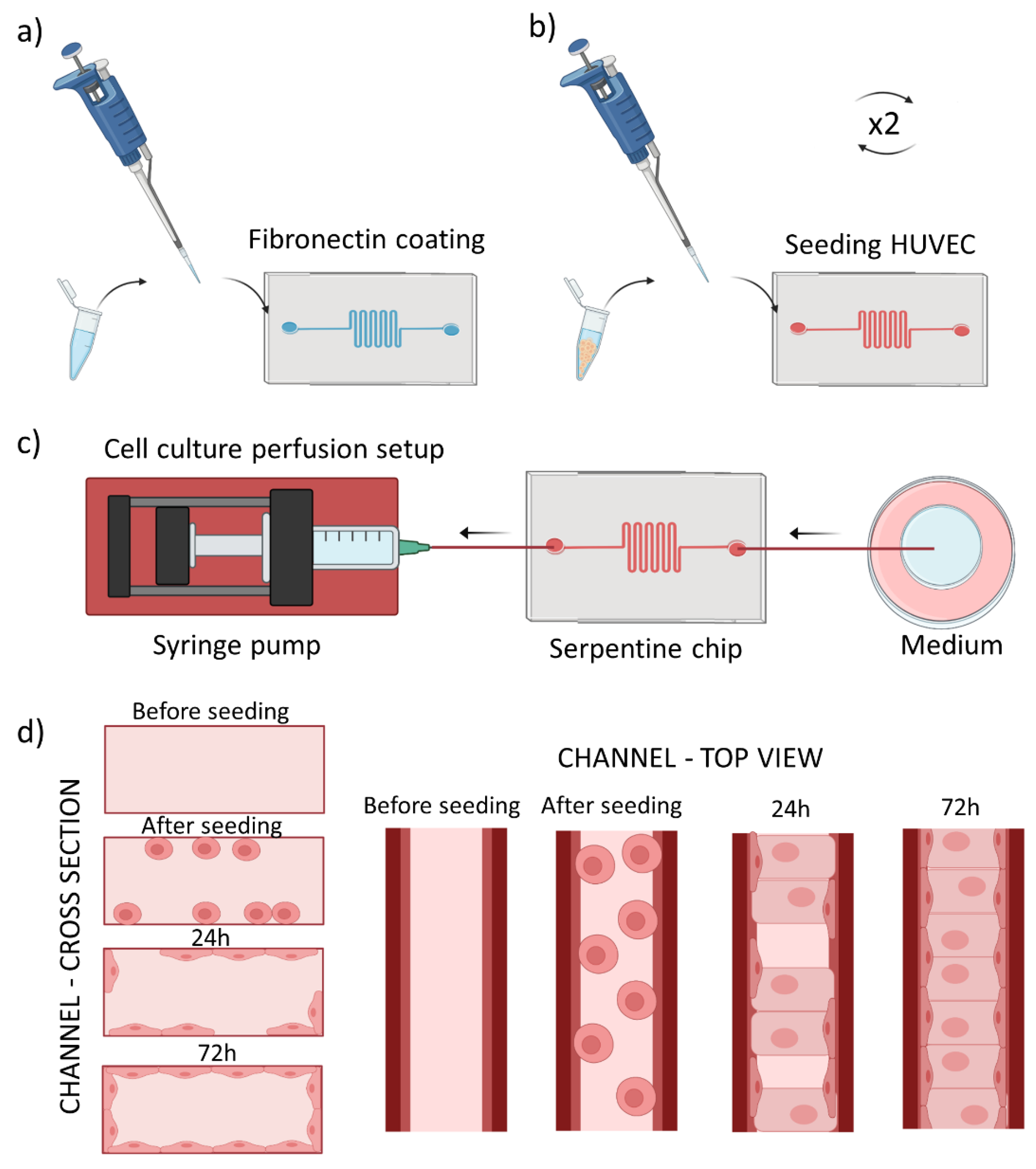
We prepared serpentine tumor blood vessel model using the PDMS chip described above. The chip was oxygen plasma-activated for 30 s, and a 50 μg/mL fibronectin (FN) (F1141-114G Fibronectin from bovine plasma, Sigma-Aldrich) injected into the microchannel and incubated for 2 h at 37 °C (Figure 1a). This step was performed to promote cell adhesion to the microfluidic channel. Next, the FN was washed away using 1× PBS (Gibco, Waltham, MA, USA). In the meantime, human umbilical vein endothelial cells (Promocell, Heidelberg, Germany) were prepared for culturing in the microchannel. They were cultured in 75 cm2 flasks at 37 °C and 5% CO2, using EndoGRO Basal Medium (Millipore, Burlington, MA, USA) supplemented with SCME001 kit (EndoGRO-LS Supplement 0.2%, rh EGF 5 ng/mL, Ascorbic Acid 50 µg/mL, l-glutamine 10 mM, hydrocortisone hemisuccinate 1 µg/mL, heparin sulfate 0.75 U/mL, FBS 2%) and penicillin/streptomycin 1% (Biowest, Riverside, MO, USA). Cells were harvested using trypsin-EDTA (0.25%, Gibco) at 70–80% confluency, centrifugated and seeded into the microfluidic channel at the density of 2.5 M cells/mL, as schematically shown in Figure 1b. The 3D culture chip was flipped upside down to allow cell adhesion to the upper plane during 2 h at 37 °C and 5% CO2. Second batch of HUVECs cultured in a separate flask was harvested and introduced to the microchannel at the same concentration as previously. The cells were then incubated for at least 2 h at 37 °C and 5% CO2 in the upright position to allow their attachment to the bottom plane. Next, the chip was perfused with EndoGRO HUVEC medium at a physiological flow rate of 0.5 µL/min, using syringe pump (Nexus Fusion 200, Chemyx, Stafford, TX, USA) during ~72 h in withdrawal mode as shown in Figure 1c, until HUVECs reached confluency. We used the withdrawal mode as it helped to minimize the generation of bubbles during the perfusion.

Figure 1.
Scheme of cell seeding into the tumor blood vessel-on-a-chip model. (a) Fibronectin coating of the microchannel, (b) Introduction of cells into the microchannel repeated twice for top and bottom plane adhesion, (c) Setup for cell culture perfusion, with the syringe pump driven withdrawal of the medium (d) scheme of the microchannel cross section (left panel) and top view (right panel) before seeding and after reaching confluent cell monolayer after the culture medium perfusion.
Figure 1d summarizes cross section/top view of one channel during all the described process steps.
2.3. Fluorescence Microscopy
2.3.1. Perfusion Setup
Images demonstrating HUVECs before and after 20 h of cell culture medium perfusion were acquired using an Eclipse Ti2 epifluorescence microscope (Nikon, Tokyo, Japan) equipped with a CoolLED system and an on-stage incubator (OKOlab, Pozzuoli, Italy) to maintain the temperature of 37 °C and atmosphere of 5% CO2. The perfusion of cell culture medium (at a physiological flow rate of 0.5 μL/min) was performed by connecting the chip to a syringe pump (Chemyx Nexus Fusion 200) using 1.0/0.5 mm OD/ID PTFE tubing (Sigma Aldrich) and setting the withdrawal mode. The other end of the microchannel was connected to a 1.5 mL tube (Eppendorf, Hamburg, Germany) with the same type of tubing.
2.3.2. Fluorescent Labelling
Cells in the microfluidic channel were perfused with 1× PBS (Gibco) and fixed with 4% paraformaldehyde (PFA, Sigma Aldrich) solution in 1× PBS. After 10 min the fixative was washed away with perfusion of 1x PBS, cells were permeabilized during 10 min with 0.1% solution of Triton X-100 (Sigma Aldrich) in 1× PBS and exposed for 1 h to 3% bovine serum albumin (BSA, Sigma Aldrich) blocking solution in 1× PBS. In the next step the cells were perfused and incubated with 1× Phalloidin-iFluor594 (Abcam, Cambridge, UK) 1000× stock solution in 1% BSA for 30 min at RT to stain actin filaments. Cellular nuclei were stained after additional washing of the cells with 1× PBS, using Hoechst 33258 (Sigma Aldrich) stain at concentration of 5 µg/mL. After 10 min. of incubation the cells were again washed with 1× PBS and imaged at RT using an LSM 800 confocal microscope (Zeiss, Oberkochen, Germany) at 405 nm and 561 nm laser excitation wavelength for nuclei and actin imaging, respectively. To plot the cell polarization under the flow conditions, a transmission image of a channel fragment was selected, and the same area analyzed before and after the 20 h of medium perfusion. The images were analyzed using OrientationJ plugin of ImageJ (NIH, New York, NY, USA) to determine the cell orientation distribution.
2.4. Transmission Electron Microscopy and Sample Prepration
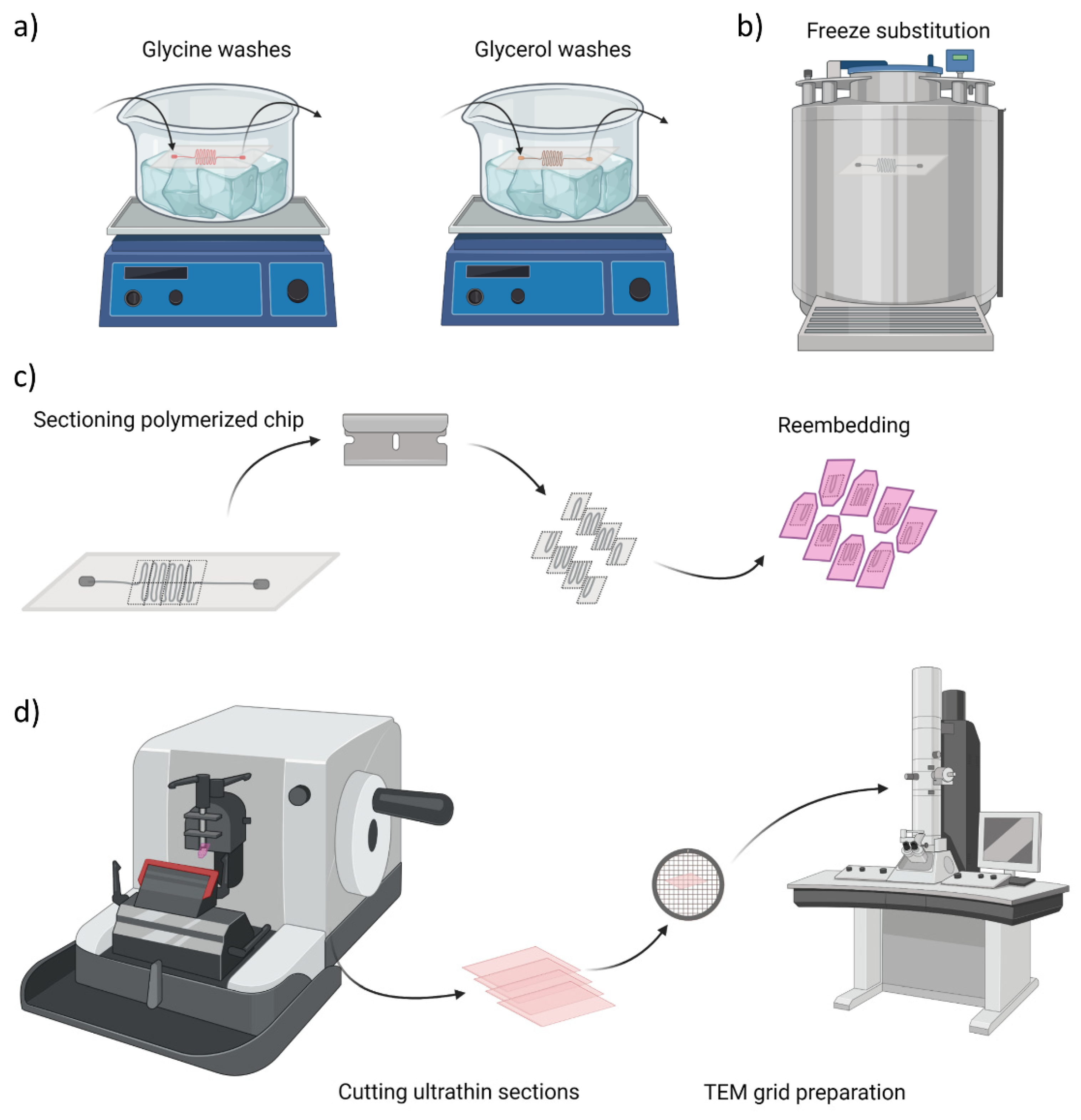
After reaching the cell confluency the chip was perfused with fixative solution containing 4% paraformaldehyde (PFA, Sigma Aldrich) and 0.1% glutaraldehyde (GA, Sigma Aldrich) in 1× PBS during 10 min and stored in solution of 2% PFA and 0.1 M PB until further processing. Next, the following steps schematically represented in Figure 2a were performed at 4 °C and with agitation: 4 washes with 0.15 M glycine (Sigma Aldrich) in 0.1 PB, 10 min. each to deactivate GA aldehyde groups. The second series of washes were done with glycerol (Sigma Aldrich), starting with 10% glycerol solution in 0.1 M PB, for 30 min, increasing the concentration to 20% (30 min) and to 30% (30 min) and again at 30% overnight. After the cryoprotection procedure, the sample was plunged rapidly into liquid propane cooled by liquid nitrogen and further processed for freeze substitution, using Leica AFS (Leica Microsystems, Vienna, Austria) as illustrated in Figure 2b. Frozen samples were transferred to a container with 0.5% uranyl acetate (EMS, Hatfield, MA, USA) in ethanol and were freeze substituted at −90 °C for 80 h. Samples were warmed up to −50 °C at 5 °C/h slope and kept at −50°C. They were rinsed with ethanol and infiltrated in Lowicryl HM20 resin (EMS) at −50 °C. Samples were polymerized under UV light: at −50 °C for 24 h, during the warming up at 5 °C/h slope till 22 °C and at 22 °C for 48 h. Figure 2c and Figure S2 schematically represents the next steps, where the region of interest (ROI) was manually trimmed by cutting away larger blocks with a hand saw and defining small serpentine blocks with razor blade. The prepared ROIs were re-embedded in HM20 and polymerized under UV light: at the same conditions as above. Finally, semithin sections of 500 nm in thickness were obtained using a Leica UC6 ultramicrotome and were observed under a Leica DM2000 optical microscope to assess the preservation of chip architecture and to localize the cells. The cells in prepared semithin sections were stained with 1% methylene blue solution for 30 s on a hotplate at 70 °C and further rinsed with purified water. Figure 2d presents an overview of the last stage, where ultrathin sections of 60 nm in thickness were obtained using Leica UC6 ultramicrotome (Leica Microsystems). Afterwards, samples prepared on carbon-coated copper grids (CF200-CU, 200 mesh, Electron Microscopy Sciences, Hatfield, PA, USA) were stained for 30 min in uranyl acetate and 5 min in lead citrate. The samples were imaged with a JEOL 1010 microscope (JEOL, Gatan, Japan) equipped with a tungsten cathode (Electron Cryomicroscopy Unit from CCiTUB, Barcelona, Spain). The images were acquired at various magnifications (×30 k–×120 k) at 80 kV with a Megaview (EMSIS GmbH, München, Germany) 1 k × 1 k CCD camera.

Figure 2.
Overview of chip sample preparation for transmission electron microscopy (TEM) imaging. (a) Glycine washes and cryoprotection step with glycerol solutions at 4 °C, (b) Freeze substitution in propane cooled down with liquid nitrogen, (c) Cutting of serpentine blocks to re-embed them in the resin for ultrathin sections preparation, (d) Schematic illustration of cutting process and final sample preparation on TEM grids.
3. Results
Using photolithography we prepared a serpentine microfluidic chip that aims to represent abnormal blood vessel in its tortuous geometry [37,38]. Figure 3 and Figure S3 show the chip channels lined with endothelial cells, reconstructing the tumor blood vessel model. To induce cell alignment, present in physiological conditions, we applied continuous perfusion of microchannel with the culture medium. The flow rate used is chosen to mimic velocity in similar size blood vessels [39,40]. (REF 39, REF 40) The shear stress created by the liquid flow results in cell alignment according to the direction of the perfusion [41,42].
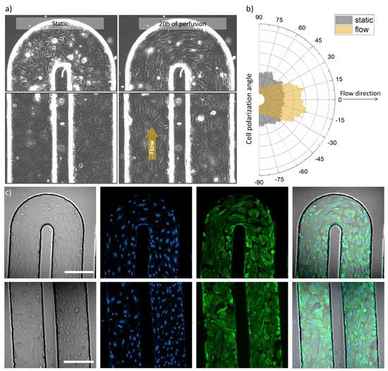
Figure 3.
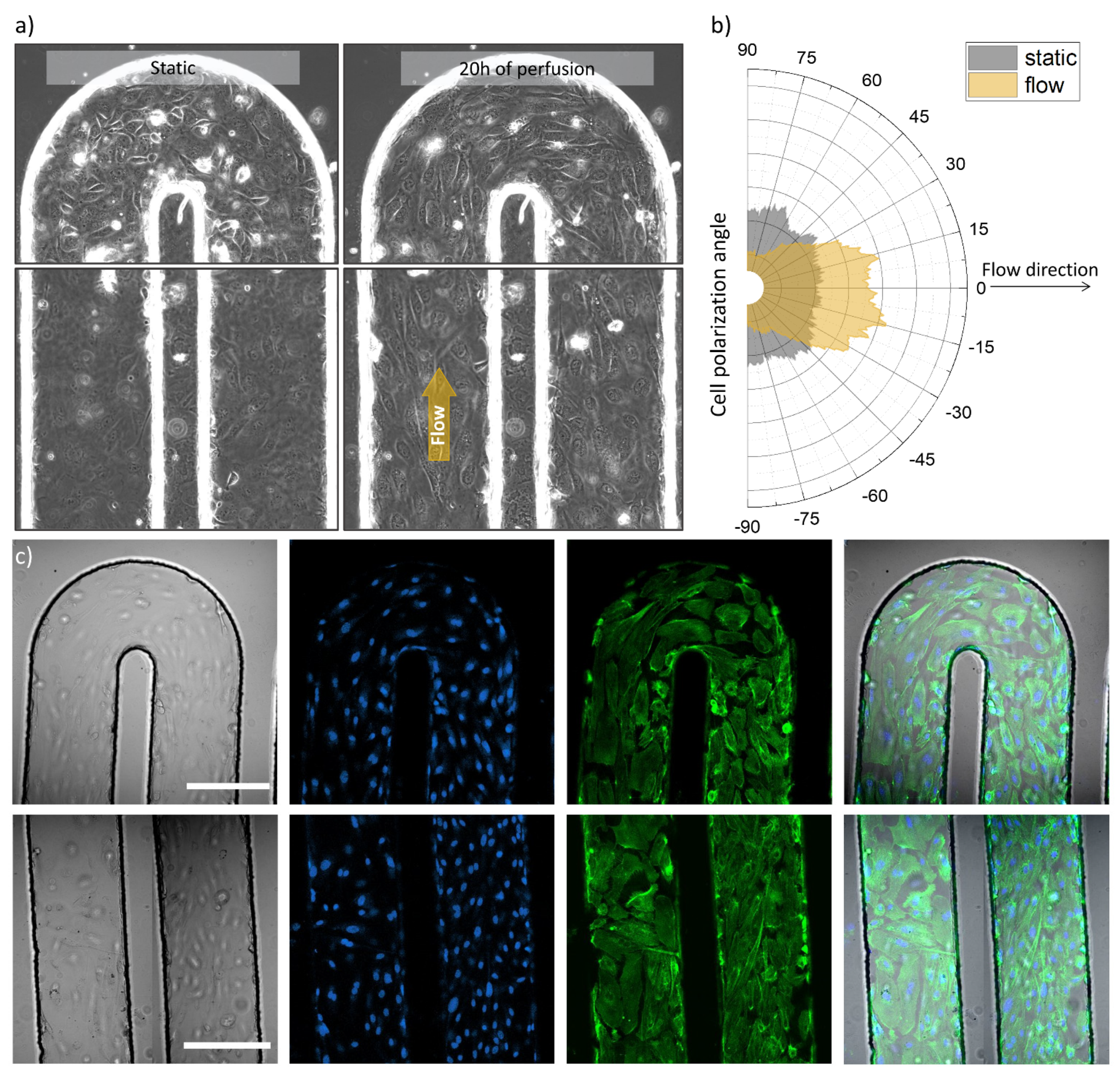
Optical and fluorescence microscopy images of the tumor blood vessel-on-a-chip model. (a) Transmission images of the serpentine U-turn (3rd turn in the row) and microchannel with seeded HUVECs before and after 20 h of cell culture media perfusion (left and right side respectively), channel width: 200 µm, (b) Graph, demonstrating cell orientation before and after cell culture medium perfusion, analyzed from the same region of the microchannel, imaged before and after the indicated perfusion time, (c) Confocal microscopy images of U-part and parallel channel parts of the serpentine (top and bottom panels, respectively) representing from left to right: transmission image, nuclei staining (blue), actin labelling (green) and overlay of the these, scale bars 200 µm.
Figure 3a shows transmission images that illustrate the microchannel with seeded and attached cells in two experimental conditions: before perfusion and after 20 h of medium perfusion driven by a syringe pump. It can be observed that the cells demonstrated movement (Video S1) and polarized along the flow direction in case of the perfused microchannel, meanwhile non-specific cell organization can be observed for the non-perfused setup as demonstrated in Figure 3b. The presence of HUVECs across folds of the microfluidic channel and in 3D was further imaged using fluorescence microscopy. Figure 3c presents confocal microscope images, acquired in two areas of the serpentine chip: at the U-turn and in parallel channels (top row and bottom row, respectively). From left to right a transmission image, cell nuclei staining, actin filament labelling and overlay images can be appreciated for both imaged areas.
We used optical and fluorescence microscopy to image endothelial cells occupying the walls and planes of the microchannel in the serpentine chip. With this method we assessed their general appearance, distribution, and density, as well as we could monitor and analyze flow-induced alignment (Figure 3, Figures S1, S3 and S4). Microscopy helped us to evaluate the condition of the prepared model, which was crucial for the next steps designed for TEM imaging.
We designed and executed the TEM sample preparation protocol (described in the previous section) to provide robust sample preparation for electron microscopy imaging. First, the cells in tumor blood vessel-on-a-chip were fixed, afterwards the microfluidic channel was perfused with polymerizable resin to ensure cell preservation and protection of microfluidic channel architecture. Furthermore, the entire chip body was immersed in the same resin to allow its infiltration through the bulk. After the polymerization (at conditions indicated in the Materials and Methods section), the resin excess was trimmed off and only the serpentine part was kept intact. The resin embedding and cutting out of redundant PDMS was performed to ensure that the chip’s soft material would not compromise the quality of the semithin or ultrathin section cutting. The polymerized, refined, and saved serpentine was further partitioned into smaller pieces, which were re-embedded in the resin, resulting in hard blocks, suitable for semi- and ultrathin sectioning (Figure S2). This second resin embedding step was to ensure proper preservation and hardening of the trimmed and selected ROIs in a shape and form compatible with the cutting equipment.
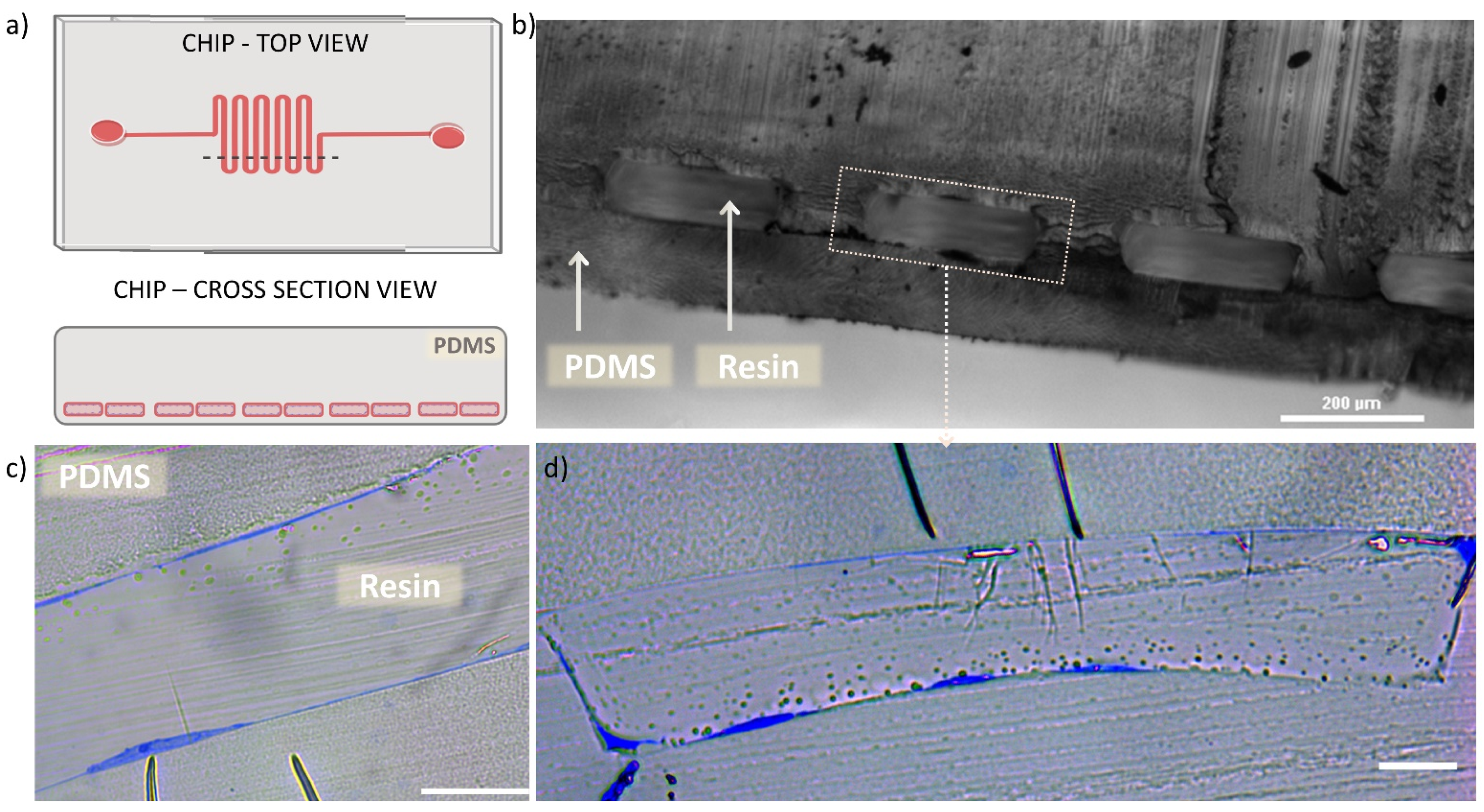
Figure 4 shows the semithin sections of microfluidic chip with HUVECs lining the channel walls, imaged prior the preparation of ultrathin sections required for the TEM technique. In Figure 4a a schematic drawing is presented to illustrate the chip top view and the corresponding cross section area (indicated by dashed line on the chip top view drawing). Figure 4b shows an optical microscope image of the cross sectioned chip, with the view on resin-filled microchannel (rectangular repeating blocks) surrounded by PDMS body. We observed uniform shape of the microchannel cross section and good preservation of the bonding between the micropatterned part and the thin PDMS bottom layer, that appeared intact after the applied procedures. Figure 4c,d show optical microscope images of semithin sections of the microfluidic channel lined with HUVECs (cells are visible in blue). Here, one can appreciate the appearance of HUVECs, present on the channel planes and vertical walls (as previously illustrated in Figure 1d) with varying thickness, depending on the cross-sectioned part of the cell. Furthermore, in Figure 4d it can be seen how the cells adapt to the rectangular shape of the microchannel, occupying the planar surfaces with stretched and “flat” morphology and the channel corners in “L”-shaped form.
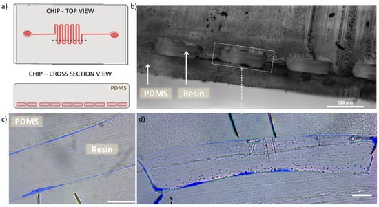
Figure 4.
Semi-thin cross sections of microchannel. (a) schematic illustration of the chip’s top view with marked dashed line indicating the cut area, resulting in cross section view on the microchannel. (b) Optical microscopy cross section image of the chip microchannel filled with polymerized resin, scale bar 200 µm. (c) optical microscope cross section image of semithin section of one of the microchannel, demonstrating the HUVEC (blue) lining on both planes of the channel, scale bar 20 µm. (d) optical microscope cross section image of semithin section of one full microchannel, demonstrating the HUVEC (blue) lining on both planes and vertical walls of the channel, as well as the cell adaptation to the rectangular channel lumen, scale bar 20 µm.
The observation of semi-thin sections allowed us to confirm that the performed process that includes multiple channel perfusions and resin polymerizations did not cause any distortion of the chip material (PDMS). The applied procedure provided preservation of the cells and the microchannel architecture as previously visualized with optical and fluorescence microscopy. Importantly, observations based on Figure 4c,d revealed the presence of HUVECs adhered onto the channel contour and immobilized them in the resin, what further guided the selection of the chip blocks to be prepared for TEM sample processing and imaging.
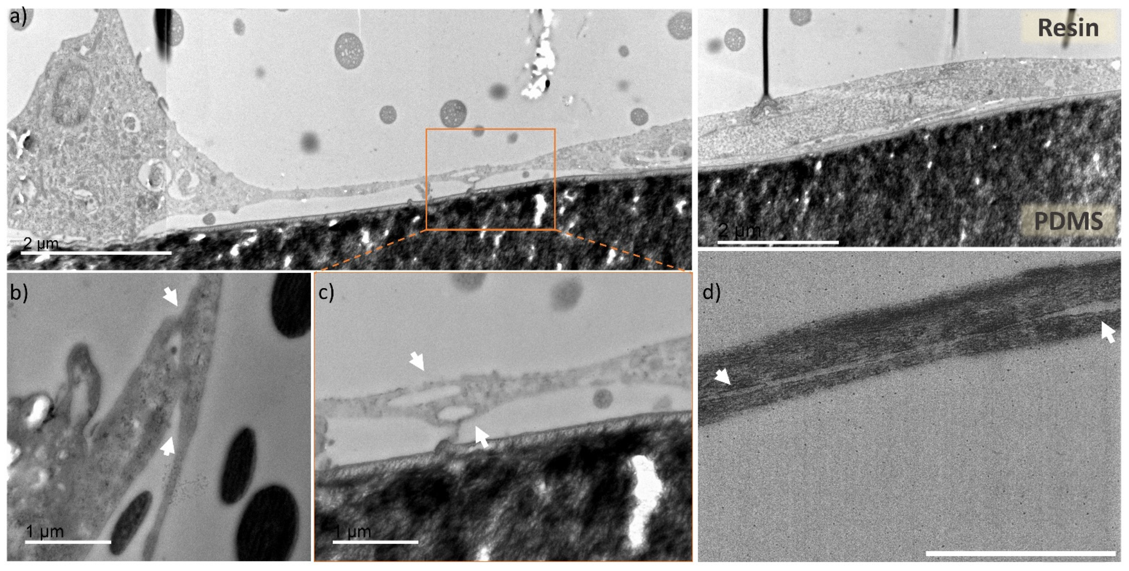
Figure 5 shows TEM imaged ultrathin cross sections of the microchannel with HUVECs prepared within the multiple steps described in the methods section. In Figure 5a one can appreciate a stitched TEM image (from three individual images), showing a cross section of a microfluidic channel fragment. There is visible “bulkier” cell (left side of the Figure 5a) conformed into the channel corner and more stretched cell (right side) at the planar surface. The image shows HUVECs adaptation to the microchannel rectangular geometry, similarly, as observed from the semithin sections imaged with optical microscope, visible in the Figure 4d.
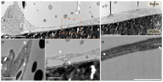
Figure 5.
TEM images of cross sections of the endothelial cells cultured in microfluidic chip. (a) cross section of a microfluidic channel fragment, with preserved cells located in the channel corner (left side) and channel planar surface (central and right part), scale bar 2 µm, (b–d) zoomed in areas with focus on two overlapping cells (indicated by white arrows) creating tight junctions in different parts of the microfluidic channels, scale bar 1 µm. (b) fragment of a cell located at the channel corner overlapping with cell stretching upward, (c) zoomed in area of two cells from the Figure 5a (indicated by dashed line box), with unrecognizable cell membrane, (d) cross section of two overlapping cells with nanogap separation between them.
In Figure 5b–d areas with captured cell-cell contact zones (indicated by white arrows) are presented. Figure 5b presents a junction of the microchannel corner-located cell with neighboring cell, stretching upwards the microchannel wall. Figure 5c is a zoomed area of Figure 5a (indicated by dashed-line square), where the connection between the two cells is very tight and uniform, and it is not possible to distinguish individual cell membrane borders, corresponding to either of them. Figure 5d presents an overlap of two cells, with a distinguishable contour of both cell membranes, as there is a nanometric gap between them (indicated by white arrows). Through TEM cell cross section imaging we observed that the overlapping HUVECs present very tight cell connection with barely visible or unnoticeable cell membrane (Figure S5). These tight junctions are a characteristic feature of endothelial cells monolayers, which serves as a barrier between the internal blood vessel lumen and outer tissues [43,44]. For the first time, to our knowledge, the processing of tumor blood vessel-on-a-chip into preserved ultrathin sections and imaging with TEM was used to capture this feature in a cross-section fashion. Overall, the images represent good cell preservation within the applied method and ultrastructural cell resolution can be appreciated (Figure S6).
For the reference, we have prepared control samples of HUVECs cultured in a traditional static 2D cell culture, which underwent the exact same sample preparation procedure as the microfluidic chip. The control 2D cell culture samples were also processed in ultrathin sections, however they were cut in a horizontal plane in the respect to the attached cell’s surface. These samples imaged with TEM (Figure S7) also demonstrated ultrastructural cell resolution. Greater level of details can be appreciated thanks to the planar cutting mode that reveals large surface of the cell, and possibly also because of easier access of chemical agents infiltrating cells, than in the case of our PDMS surrounded HUVECs, cultured in the microfluidic channel. However, the overall cell condition and preservation is similar between the presented microfluidic chip cross sections and the 2D reference sample.
4. Discussion
We have developed a method for microfluidic organ-on-a-chip cross section sample preparation compatible with transmission electron microscopy imaging to reveal ultrastructural cell characteristics. The proposed protocol consists of multiple microchannel perfusions with media providing cell fixation, structure preservation, dehydration and cryoprotection. In the OoC technology the careful handling of cell culture and treatment of microchannels is a key factor for successful experimental outcome, as these microstructures and cells can withstand limited pressure, and air bubbles should be avoided at any time. For this reason, these liquids were subsequently and gently introduced using connection tubing and small volume syringe or a syringe pump to minimize potential risk of damaging the cells or microchannels. These steps allowed us to successfully preserve the cells in the microchannel, where they were cultured. Importantly, the microchannel architecture was maintained in its original shape (as designed with width and height of about 200 µm and 60 µm), without any visible distortion. Furthermore, the bonding between the micropatterned chip layer and bottom enclosing layer appeared intact (no tears or gaps, as visible in Figure 4b). To achieve this final condition after the applied multiple serpentine perfusion steps, we relied on double resin embedding and polymerization to obtain robust samples for cutting procedure.
As known and presented here, the TEM technique is suitable for the characterization of nano- and submicron structures, however it is not explored in combination with the OoC technology. Currently the extraction of the structures of interest from the chip environment, or the deconstruction of microfabricated architecture are used to facilitate further analysis with this microscopy technique [35,36]. The reason is the lack of standard processing method, as the preservation and staining of biological specimen in microfluidic channels are not obvious, nor optimized. One of the concerns is that the microchannels are protected by PDMS bulk, that limits cells’ accessibility for a contact and infiltration with the mentioned agents. Second, these liquids have different properties, such as viscosity or volatility, that need to be considered when perfusing them gently but with optimal pace through microchannels. Furthermore, it is important to rely on a robust sample preparation method with compatible chemical substances, as the PDMS is not particularly resistant to many organic agents.
Within the images obtained from semithin sections (Figure 4), we could evaluate the impact of the applied procedure on the final conditions of the microfluidic channel. These images confirmed the good preservation of the microchannel geometry, PDMS-PDMS bonding and importantly, they revealed the presence of endothelial cell lining on the channel surface. Furthermore, by processing the full chip, without its deconstruction, we could observe a remarkable adaptation of endothelial cells to the rectangular cross-section of the microfluidic channel (Figure 4 and Figure 5). HUVECs appeared “flatter” and more stretched when localized on a planar area, comparing to more compact cells noticed in the channel corners. Such rectangular microchannel geometry is not fully representative in terms of physiological conditions, where more circular shapes exist, however the chip microfabrication technique allows only for such outcome. Nevertheless, the proposed procedure could be applied for PDMS microfluidic chip with any channel cross section shape, as for example circular blood vessel reported in the literature [45], thus, giving insights about the structure and morphology of endothelial cells within the microfluidic channel.
Furthermore, we obtained high resolution images of endothelial cells cross section, presenting well preserved tight junctions, which otherwise can be labelled and visualized in fluorescence microscopy, as we have reported in our other work on a tumor blood vessel model [17]. However there the level of detail is limited, due to the optical microscopy resolution constraints. In addition, the image detail accuracy worsens with the increasing sample thickness and density, which is the case for 3D cell culture microfluidic channels. The tight junctions are nanometric scale features, which also appear at very thin areas where cells overlap (Figure 5 and Figure S5), thus TEM imaging provided very good level of detail irrespective of the channel height. The acquired images revealed similar quality and morphology to others reported in the literature for HUVECs cross-sections, grown on Transwell membranes [34]. It is impressive to be able to appreciate these details, considering the extended procedure of sample preparation that was applied to facilitate processing of entire microfluidic chip, without prior extraction or destruction of the microfluidic channel.
We optimized this protocol for PDMS microfluidic chip on the example of tumor blood vessel model. One of the bioengineering applications for such device can be preclinical screening of drugs or drug nanocarriers, such as submicron and nano- sized particles. In the case of the latter, the optically transparent bottom chip layer permits one to monitor the particle trajectory and internalization under physiologically relevant flow conditions using transmission and fluorescence microscopy [46,47,48]. We presented the tumor blood vessel-on-a-chip model as suitable for perfusion-based experiments, as demonstrated above with the flow induced HUVECs alignment in the microchannels (Figure 3). Furthermore, we introduced to the same model (not presented in the results) fluorescent nanoparticles under the flow conditions (Video S2 and S3), where their trajectory could be followed.
An interesting example for endothelial cells studies that could employ the proposed tumor blood vessel model and TEM sample preparation method is the use of gold nanoparticles, which are reported to alter tight junctions and increase paracellular permeability [49]. More than that, gold nanoparticles present high electron density suitable for TEM imaging, and they can be synthesized to yield different shapes. Moreover, studies focused on NPs internalization pathway, biocompatibility or toxicity evaluation could be carried out under flow and in static conditions using the presented microfluidic chip, and the experimental outcomes supported by TEM image-based analysis [38,50,51,52].
Moreover, the presented chip could be used to study tumor vasculature leakiness, a controversial phenomenon known as enhanced permeability and retention (EPR) effect, crucial for the design and development of successful nanocarriers [53,54].
We believe that the TEM preparation workflow presented here is universal and not limited to our chip design, it could be used for other types of chips as long as the fabrication material is PDMS. For other types of fabrication materials, the protocol should be adapted to withstand the solvents used during pre-embedding.
5. Conclusions
In summary we demonstrated in this work a TEM sample preparation method that allows one to process and image 3D cultured cells in a PDMS microfluidic chip. The presented method successfully preserved endothelial cells in the microchannel, and the TEM imaging provided resolution, which allowed cell ultrastructural characterization. The cross-section cuts facilitated remarkable observation of the HUVEC adaptation to the microchannel rectangular shape. In this work we provided a supportive analysis method based on TEM imaging, that can contribute to the characterization of OoC models without their prior deconstruction.
Supplementary Materials
The following are available online at https://www.mdpi.com/article/10.3390/applnano2040021/s1, Figure S1: Serpentine microfluidic chip used to prepare the tumor blood vessel-on-a-chip model. Figure S2: Preparation of microfluidic chip blocks for semithin and ultrathin sections cutting. Figure S3: Optical and fluorescence microscopy images of the tumor blood vessel-on-a-chip model. Figure S4: 3D reconstruction of confocal microscopy images, representing the U-shaped bottom part of the serpentine chip lined with endothelial cells. Figure S5: TEM images of cross sections of the endothelial cells cultured in microfluidic chip. Figure S6: Ultrastructural resolution TEM images of cross sections of the endothelial cells cultured in microfluidic chip and preserved in the resin. Figure S7: Reference sample of endothelial cells grown in traditional 2D cell culture. Video S1: Perfusion of microfluidic channel inducing cell polarization. Video S2: Perfusion of microfluidic channel with fluorescent nanoparticles in cell culture medium. Video S3: Perfusion of microfluidic channel with fluorescent nanoparticles in blood
Author Contributions
Conceptualization: S.P., A.G.M. and N.F.-G.; Methodology, all authors; Investigation, A.G.M., N.F.-G., Y.M., G.M. and S.P.; Writing—original draft preparation: A.G.M.; Writing—review and editing, A.G.M. and S.P.; Visualization, A.G.M.; Supervision, S.P. and L.A. All authors have read and agreed to the published version of the manuscript.
Funding
This research was funded by by Spanish Ministry of Science and Innovation (PID2019-109450RB-I00/AEI/10.13039/501100011033), European Research Council/Horizon 2020 (ERC-StG-757397), la Caixa Foundation (ID 100010434) and by the Generalitat de Catalunya (2017 SGR 01536) to S.P. and L.A., A.G.M. received the support of a fellowship from “la Caixa” Foundation (ID 1000010434). The fellowship code of A.G.M. is LCF/BQ/DI17/11620054. A.G.M has received funding from the European Union’s Horizon 2020 research and innovation programme under the Marie Skłodowska-Curie Grant Agreement No. 713673.
Data Availability Statement
Data is contained within the article or supplementary material.
Acknowledgments
The illustrations presented in the manuscript Figures were created with Biorender.com (accessed on 10 September 2021). A.G.M. would like to acknowledge the support of David Izquierdo (IBEC) in microfabrication activities and Roberto Paoli (IBEC) for letting us use his serpentine chip design.
Conflicts of Interest
The authors declare no conflict of interest.
References
- Breslin, S.; O’Driscoll, L. Three-dimensional cell culture: The missing link in drug discovery. Drug Discov. Today 2013, 18, 240–249. [Google Scholar] [CrossRef] [PubMed]
- Abbott, A. Biology’s new dimension. Nat. Cell Biol. 2003, 424, 870–872. [Google Scholar] [CrossRef] [PubMed]
- Leong, D.T.; Ng, K.W. Probing the relevance of 3D cancer models in nanomedicine research. Adv. Drug Deliv. Rev. 2014, 79-80, 95–106. [Google Scholar] [CrossRef] [PubMed]
- Hassell, B.; Goyal, G.; Lee, E.; Sontheimer-Phelps, A.; Levy, O.; Chen, C.; Ingber, D.E. Human organ chip models recapitulate orthotopic lung cancer growth, therapeutic responses, and tumor dormancy in vitro. Cell Rep. 2017, 21, 508–516. [Google Scholar] [CrossRef] [PubMed] [Green Version]
- Henry, O.Y.F.; Villenave, R.; Cronce, M.J.; Leineweber, W.D.; Benz, M.A.; Ingber, D.E. Organs-on-chips with integrated electrodes for trans-epithelial electrical resistance (TEER) measurements of human epithelial barrier function. Lab Chip 2017, 17, 2264–2271. [Google Scholar] [CrossRef] [PubMed]
- Thompson, C.L.; Fu, S.; Heywood, H.K.; Knight, M.M.; Thorpe, S.D. Mechanical stimulation: A crucial element of organ-on-chip models. Front. Bioeng. Biotechnol. 2020, 8, 602646. [Google Scholar] [CrossRef]
- Ashammakhi, N.; Nasiri, R.; de Barros, N.R.; Tebon, P.; Thakor, J.; Goudie, M.; Shamloo, A.; Martin, M.G.; Khademhosseini, A. Gut-on-a-chip: Current progress and future opportunities. Biomaterials 2020, 255, 120196. [Google Scholar] [CrossRef] [PubMed]
- Gupta, N.; Liu, J.; Patel, B.; Solomon, D.E.; Vaidya, B.; Gupta, V. Microfluidics-based 3D cell culture models: Utility in novel drug discovery and delivery research. Bioeng. Transl. Med. 2016, 1, 63–81. [Google Scholar] [CrossRef]
- Caddeo, S.; Boffito, M.; Sartori, S. Tissue engineering approaches in the design of healthy and pathological in vitro tissue models. Front. Bioeng. Biotechnol. 2017, 5, 40. [Google Scholar] [CrossRef] [Green Version]
- Carletti, E.; Motta, A.; Migliaresi, C. Scaffolds for tissue engineering and 3D cell culture. In Methods in Molecular Biology; Springer Science and Business Media LLC.: Berlin, Germany, 2010; Volume 695, pp. 17–39. [Google Scholar]
- Griffith, L.G.; Swartz, M.A. Capturing complex 3D tissue physiology in vitro. Nat. Rev. Mol. Cell Biol. 2006, 7, 211–224. [Google Scholar] [CrossRef]
- Franco, C.; Gerhardt, H. Blood vessels on a chip. Nat. Cell Biol. 2012, 488, 465–466. [Google Scholar] [CrossRef]
- Chen, Y.; Gao, D.; Wang, Y.; Lin, S.; Jiang, Y. A novel 3D breast-cancer-on-chip platform for therapeutic evaluation of drug delivery systems. Anal. Chim. Acta 2018, 1036, 97–106. [Google Scholar] [CrossRef]
- Nashimoto, Y.; Okada, R.; Hanada, S.; Arima, Y.; Nishiyama, K.; Miura, T.; Yokokawa, R. Vascularized cancer on a chip: The effect of perfusion on growth and drug delivery of tumor spheroid. Biomaterials 2020, 229, 119547. [Google Scholar] [CrossRef] [PubMed]
- Fang, J.; Nakamura, H.; Maeda, H. The EPR effect: Unique features of tumor blood vessels for drug delivery, factors involved, and limitations and augmentation of the effect. Adv. Drug Deliv. Rev. 2011, 63, 136–151. [Google Scholar] [CrossRef]
- Ko, J.; Ahn, J.; Kim, S.; Lee, Y.; Lee, J.; Park, D.; Jeon, N.L. Tumor spheroid-on-a-chip: A standardized microfluidic culture platform for investigating tumor angiogenesis. Lab Chip 2019, 19, 2822–2833. [Google Scholar] [CrossRef]
- Feiner-Gracia, N.; Mares, A.G.; Buzhor, M.; Rodriguez-Trujillo, R.; Marti, J.S.; Amir, R.J.; Pujals, S.; Albertazzi, L. Real-time ratiometric imaging of micelles assembly state in a microfluidic cancer-on-a-chip. ACS Appl. Bio Mater. 2021, 4, 669–681. [Google Scholar] [CrossRef]
- Weibel, D.B.; DiLuzio, W.R.; Whitesides, G.M. Microfabrication meets microbiology. Nat. Rev. Microbiol. 2007, 5, 209–218. [Google Scholar] [CrossRef]
- Haycock, J.W. 3D Cell Culture: A Review of Current Approaches and Techniques; Springer Science and Business Media LLC.: Amsterdam, The Netherlands, 2010; Volume 695, pp. 1–15. [Google Scholar]
- Zhang, B.; Korolj, A.; Lai, B.F.L.; Radisic, M. Advances in organ-on-a-chip engineering. Nat. Rev. Mater. 2018, 3, 257–278. [Google Scholar] [CrossRef]
- Li, Y.; Pi, Q.-M.; Wang, P.-C.; Liu, L.-J.; Han, Z.-G.; Shao, Y.; Zhai, Y.; Zuo, Z.-Y.; Gong, Z.-Y.; Yang, X.; et al. Functional human 3D microvascular networks on a chip to study the procoagulant effects of ambient fine particulate matter. RSC Adv. 2017, 7, 56108–56116. [Google Scholar] [CrossRef] [Green Version]
- Xiao, Y.; Kim, D.; Dura, B.; Zhang, K.; Yan, R.; Li, H.; Han, E.; Ip, J.; Zou, P.; Liu, J.; et al. Ex vivo Dynamics of Human Glioblastoma Cells in a Microvasculature-on-a-Chip System Correlates with Tumor Heterogeneity and Subtypes. Adv. Sci. 2019, 6, 1801531. [Google Scholar] [CrossRef] [Green Version]
- Maidorn, M.; Rizzoli, S.O.; Opazo, F. Tools and limitations to study the molecular composition of synapses by fluorescence microscopy. Biochem. J. 2016, 473, 3385–3399. [Google Scholar] [CrossRef] [PubMed]
- Van Meerbeek, B.; Vargas, M.; Inoue, S.; Yoshida, Y.; Perdigão, J.; Lambrechts, P.; Vanherle, G. Microscopy investigations. Techniques, results, limitations. Am. J. Dent. 2000, 13, 3–18. [Google Scholar]
- Charwat, V.; Schütze, K.; Holnthoner, W.; Lavrentieva, A.; Gangnus, R.; Hofbauer, P.; Hoffmann, C.; Angres, B.; Kasper, C. Potential and limitations of microscopy and Raman spectroscopy for live-cell analysis of 3D cell cultures. J. Biotechnol. 2015, 205, 70–81. [Google Scholar] [CrossRef]
- Nguyen, T.-A.; Yin, T.-I.; Reyes, D.; Urban, G.A. Microfluidic Chip with integrated electrical cell-impedance sensing for monitoring single cancer cell migration in three-dimensional matrixes. Anal. Chem. 2013, 85, 11068–11076. [Google Scholar] [CrossRef]
- Velasco, V.; Joshi, K.; Chen, J.; Esfandyarpour, R. Personalized drug efficacy monitoring chip. Anal. Chem. 2019, 91, 14927–14935. [Google Scholar] [CrossRef]
- Weltin, A.; Slotwinski, K.; Kieninger, J.; Moser, I.; Jobst, G.; Wego, M.; Ehret, R.; Urban, G.A. Cell culture monitoring for drug screening and cancer research: A transparent, microfluidic, multi-sensor microsystem. Lab Chip 2014, 14, 138–146. [Google Scholar] [CrossRef] [PubMed]
- Bavli, D.; Prill, S.; Ezra, E.; Levy, G.; Cohen, M.; Vinken, M.; Vanfleteren, J.; Jaeger, M.; Nahmias, Y. Real-time monitoring of metabolic function in liver-on-chip microdevices tracks the dynamics of mitochondrial dysfunction. Proc. Natl. Acad. Sci. USA 2016, 113, E2231–E2240. [Google Scholar] [CrossRef] [PubMed] [Green Version]
- Maoz, B.M.; Herland, A.; Henry, O.Y.F.; Leineweber, W.D.; Yadid, M.; Doyle, J.; Mannix, R.; Kujala, V.J.; FitzGerald, E.A.; Parker, K.K.; et al. Organs-on-Chips with combined multi-electrode array and transepithelial electrical resistance measurement capabilities. Lab Chip 2017, 17, 2294–2302. [Google Scholar] [CrossRef] [PubMed]
- Bhatia, S.N.; Ingber, D.E. Microfluidic organs-on-chips. Nat. Biotechnol. 2014, 32, 760–772. [Google Scholar] [CrossRef]
- Malatesta, M. Transmission electron microscopy for nanomedicine: Novel applications for long-established techniques. Eur. J. Histochem. 2016, 60, 2751. [Google Scholar] [CrossRef] [Green Version]
- Sun, J.; Liu, X. Potential proinflammatory effects of hydroxyapatite nanoparticles on endothelial cells in a monocyte–endothelial cell coculture model. Int. J. Nanomed. 2014, 9, 1261–1273. [Google Scholar] [CrossRef] [Green Version]
- Da Silva, M.L.; von Cutler, D.F. Willebrand factor multimerization and the polarity of secretory pathways in endothelial cells. Blood 2016, 128, 277–285. [Google Scholar] [CrossRef] [Green Version]
- Shim, K.-Y.; Lee, D.; Han, J.; Nguyen, N.-T.; Park, S.; Sung, J.H. Microfluidic gut-on-a-chip with three-dimensional villi structure. Biomed. Microdevices 2017, 19, 37. [Google Scholar] [CrossRef] [Green Version]
- Achberger, K.; Probst, C.; Haderspeck, J.; Bolz, S.; Rogal, J.; Chuchuy, J.; Nikolova, M.; Cora, V.; Antkowiak, L.; Haq, W.; et al. Merging organoid and organ-on-a-chip technology to generate complex multi-layer tissue models in a human retina-on-a-chip platform. eLife 2019, 8, 46188. [Google Scholar] [CrossRef] [PubMed]
- A Nagy, J.; Chang, S.-H.; Dvorak, A.M.; Dvorak, H.F. Why are tumour blood vessels abnormal and why is it important to know? Br. J. Cancer 2009, 100, 865–869. [Google Scholar] [CrossRef] [PubMed]
- Llenas, M.; Paoli, R.; Feiner-Gracia, N.; Albertazzi, L.; Samitier, J.; Caballero, D. Versatile vessel-on-a-chip platform for studying key features of blood vascular tumors. Bioengineering 2021, 8, 81. [Google Scholar] [CrossRef]
- Tsvirkun, D.; Grichine, A.; Duperray, A.; Misbah, C.; Bureau, L. Microvasculature on a chip: Study of the endothelial surface layer and the flow structure of red blood cells. Sci. Rep. 2017, 7, srep45036. [Google Scholar] [CrossRef] [PubMed]
- Eskin, S.; Ives, C.; McIntire, L.; Navarro, L. Response of cultured endothelial cells to steady flow. Microvasc. Res. 1984, 28, 87–94. [Google Scholar] [CrossRef]
- Kroon, J.; Heemskerk, N.; Kalsbeek, M.J.T.; De Waard, V.; van Rijssel, J.; Van Buul, J.D. Flow-induced endothelial cell alignment requires the RhoGEF Trio as a scaffold protein to polarize active Rac1 distribution. Mol. Biol. Cell 2017, 28, 1745–1753. [Google Scholar] [CrossRef] [PubMed]
- Sinha, R.; Le Gac, S.; Verdonschot, N.; Berg, A.V.D.; Koopman, H.F.; Rouwkema, J. Endothelial cell alignment as a result of anisotropic strain and flow induced shear stress combinations. Sci. Rep. 2016, 6, 29510. [Google Scholar] [CrossRef] [PubMed]
- Tornavaca, O.; Chia, M.; Dufton, N.; Almagro, L.O.; Conway, D.E.; Randi, A.M.; Schwartz, M.A.; Matter, K.; Balda, M.S. ZO-1 controls endothelial adherens junctions, cell–cell tension, angiogenesis, and barrier formation. J. Cell Biol. 2015, 208, 821–838. [Google Scholar] [CrossRef] [PubMed] [Green Version]
- Barua, S.; Mitragotri, S. Challenges associated with penetration of nanoparticles across cell and tissue barriers: A review of current status and future prospects. Nano Today 2014, 9, 223–243. [Google Scholar] [CrossRef] [PubMed]
- Costa, P.; Albers, H.J.; Linssen, J.E.A.; Middelkamp, H.H.T.; Van Der Hout, L.; Passier, R.; van den Berg, A.; Malda, J.; Van Der Meer, A.D. Mimicking arterial thrombosis in a 3D-printed microfluidic in vitro vascular model based on computed tomography angiography data. Lab Chip 2017, 17, 2785–2792. [Google Scholar] [CrossRef] [PubMed] [Green Version]
- D’Apolito, R.; Tomaiuolo, G.; Taraballi, F.; Minardi, S.; Kirui, D.; Liu, X.; Cevenini, A.; Palomba, R.; Ferrari, M.; Salvatore, F.; et al. Red blood cells affect the margination of microparticles in synthetic microcapillaries and intravital microcirculation as a function of their size and shape. J. Control. Release 2015, 217, 263–272. [Google Scholar] [CrossRef] [PubMed] [Green Version]
- Doshi, N.; Prabhakarpandian, B.; Rea-Ramsey, A.; Pant, K.; Sundaram, S.; Mitragotri, S. Flow and adhesion of drug carriers in blood vessels depend on their shape: A study using model synthetic microvascular networks. J. Control. Release 2010, 146, 196–200. [Google Scholar] [CrossRef] [Green Version]
- Klingberg, H.; Loft, S.; Oddershede, L.B.; Møller, P. The influence of flow, shear stress and adhesion molecule targeting on gold nanoparticle uptake in human endothelial cells. Nanoscale 2015, 7, 11409–11419. [Google Scholar] [CrossRef]
- Li, C.-H.; Shyu, M.-K.; Jhan, C.; Cheng, Y.-W.; Tsai, C.-H.; Liu, C.-W.; Lee, C.-C.; Chen, R.-M.; Kang, J.-J. Gold Nanoparticles increase endothelial paracellular permeability by altering components of endothelial tight junctions, and increase blood-brain barrier permeability in mice. Toxicol. Sci. 2015, 148, 192–203. [Google Scholar] [CrossRef] [Green Version]
- Fede, C.; Fortunati, I.; Weber, V.; Rossetto, N.; Bertasi, F.; Petrelli, L.; Guidolin, D.; Signorini, R.; De Caro, R.; Albertin, G.; et al. Evaluation of gold nanoparticles toxicity towards human endothelial cells under static and flow conditions. Microvasc. Res. 2015, 97, 147–155. [Google Scholar] [CrossRef]
- Bartczak, D.; Muskens, O.L.; Nitti, S.; Sanchez-Elsner, T.; Millar, T.M.; Kanaras, A.G. Interactions of Human Endothelial Cells with Gold Nanoparticles of Different Morphologies. Small 2012, 8, 122–130. [Google Scholar] [CrossRef]
- Orlando, A.; Colombo, M.; Prosperi, D.; Corsi, F.; Panariti, A.; Rivolta, I.; Masserini, M.; Cazzaniga, E. Evaluation of gold nanoparticles biocompatibility: A multiparametric study on cultured endothelial cells and macrophages. J. Nanopart. Res. 2016, 18, 1–12. [Google Scholar] [CrossRef]
- Nakamura, Y.; Mochida, A.; Choyke, P.L.; Kobayashi, H. Nanodrug Delivery: Is the Enhanced Permeability and Retention Effect Sufficient for Curing Cancer? Bioconjug. Chem. 2016, 27, 2225–2238. [Google Scholar] [CrossRef]
- Shi, Y.; Van Der Meel, R.; Chen, X.; Lammers, T. The EPR effect and beyond: Strategies to improve tumor targeting and cancer nanomedicine treatment efficacy. Theranostics 2020, 10, 7921–7924. [Google Scholar] [CrossRef] [PubMed]
Publisher’s Note: MDPI stays neutral with regard to jurisdictional claims in published maps and institutional affiliations. |
© 2021 by the authors. Licensee MDPI, Basel, Switzerland. This article is an open access article distributed under the terms and conditions of the Creative Commons Attribution (CC BY) license (https://creativecommons.org/licenses/by/4.0/).