
Recent Advancements in Na Super Ionic Conductor-Incorporated Composite Polymer Electrolytes for Sodium-Ion Battery Application

 and
and
Abstract
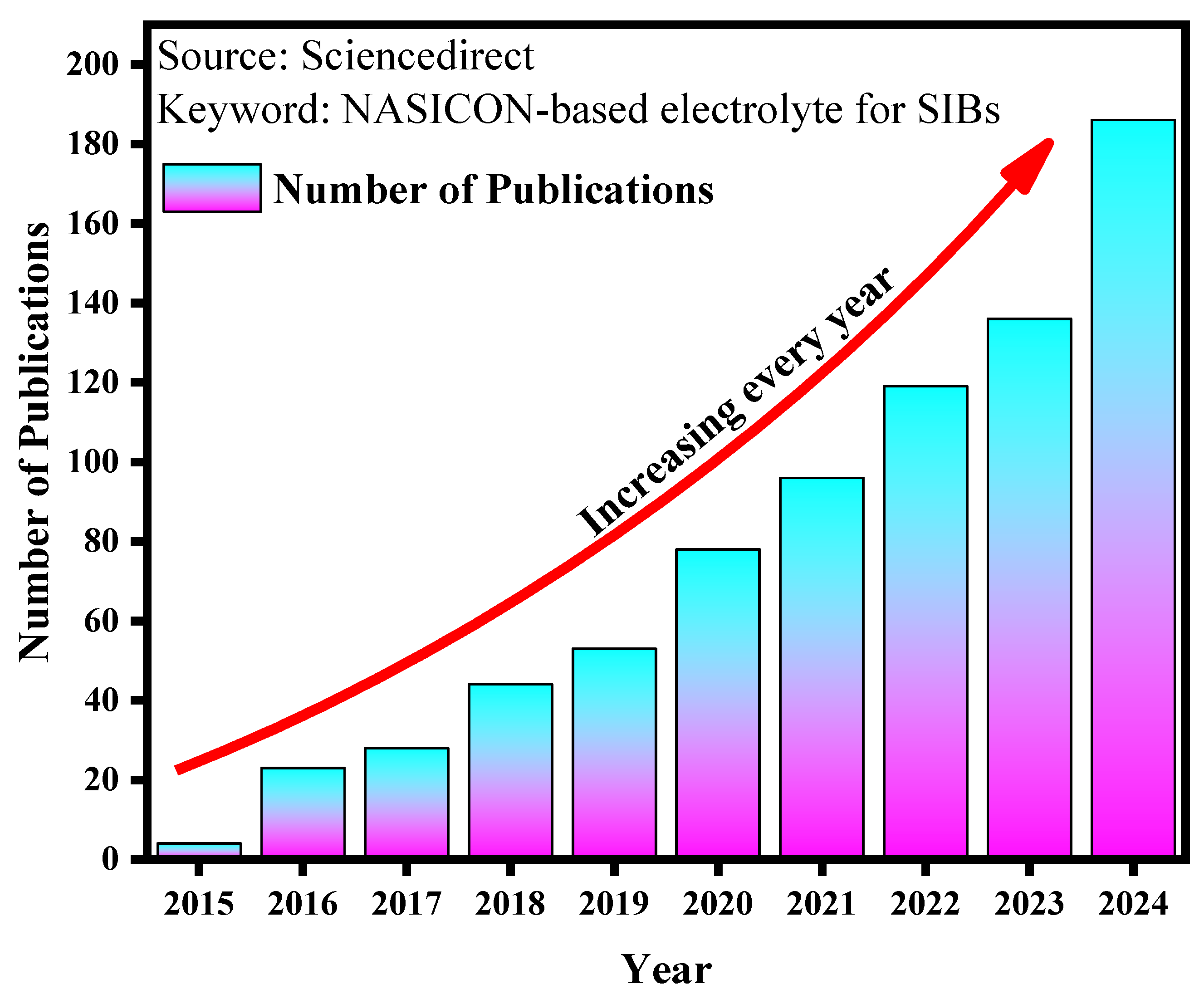
1. Introduction
- Inorganic solid electrolytes (ISEs),
- Solid polymer electrolytes (SPEs),
- Composite polymer electrolytes (CPEs).
1.1. Inorganic Solid Electrolytes (ISEs)
1.2. Solid Polymer Electrolytes (SPEs)
1.3. Composite Polymer Electrolytes (CPEs)
- In ceramic-in-polymer systems, ceramic particles are added in lesser amounts to a polymer matrix. This improves ionic conductivity by reducing polymer crystallization or creating a conductive interface between the polymer and ceramic fillers while maintaining easy processability [36].
- In polymer-in-ceramic systems, the ceramic content exceeds 50%, making ceramics the dominant phase. These systems offer higher mechanical strength and safety, making them ideal for large solid-state battery packs, such as those in electric vehicles [36].
2. NASICON Fillers: Preparation, Structure, and Morphology
2.1. General Structure of NASICON
- i.
- A represents alkali cations (e.g., Li, Na, K);
- ii.
- M and M′ are transition metals (e.g., Fe, Ti, Zr);
- iii.
- X denotes elements such as phosphorus or silicon;
- iv.
- n can vary from 1 to 4.
- a.
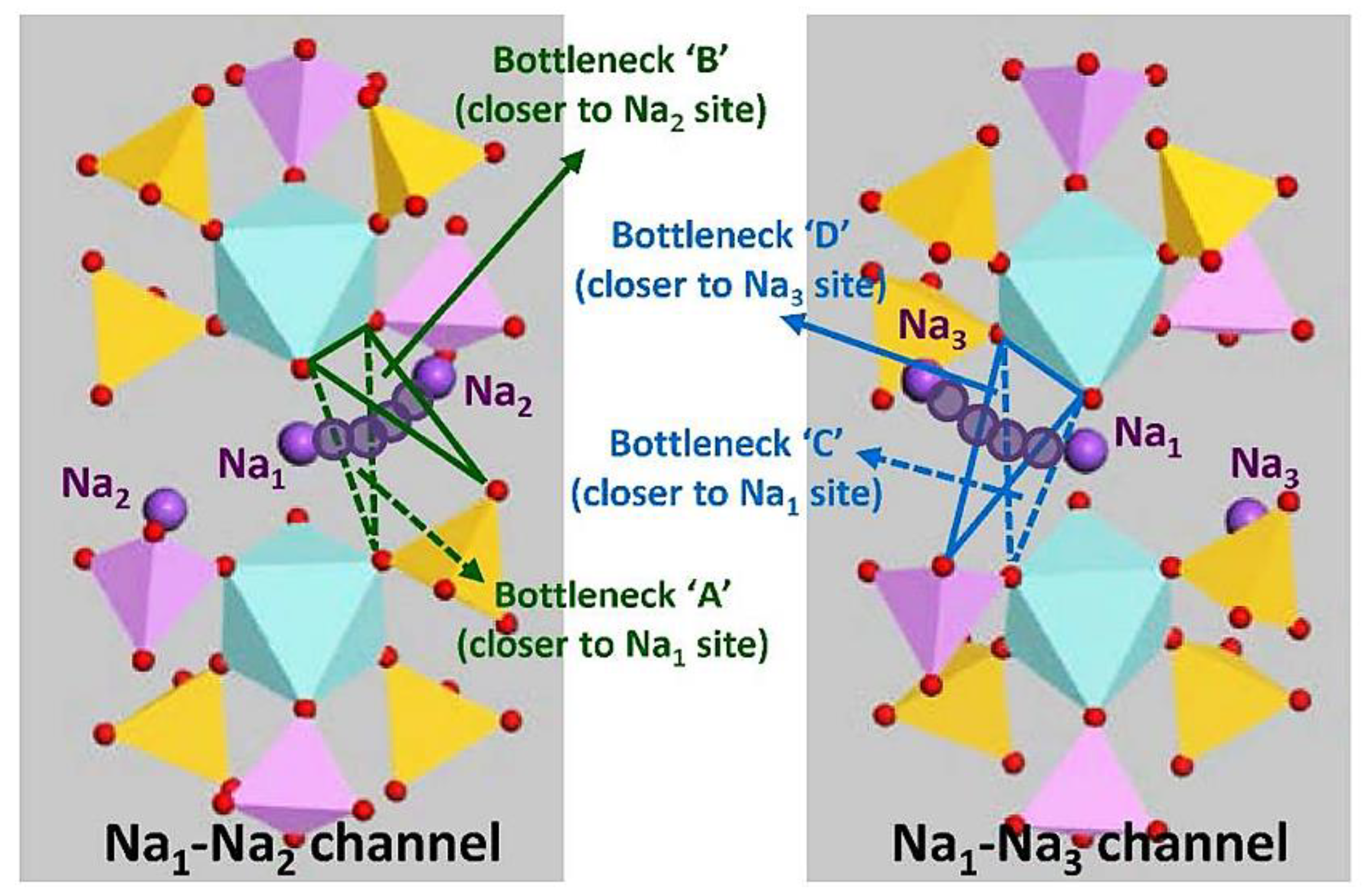
- M1 sites (octahedral) are tightly packed, with sodium ions that move very little. The sodium ions located at the M1 sites are tightly bound to the surrounding coordinated oxygen atoms.
- b.
- M2 sites are larger and can accommodate more sodium ions, which can move more freely.
Description of ‘Bottleneck’ Structure
2.2. Na3Zr2Si2PO12-Based NASICON-Outline
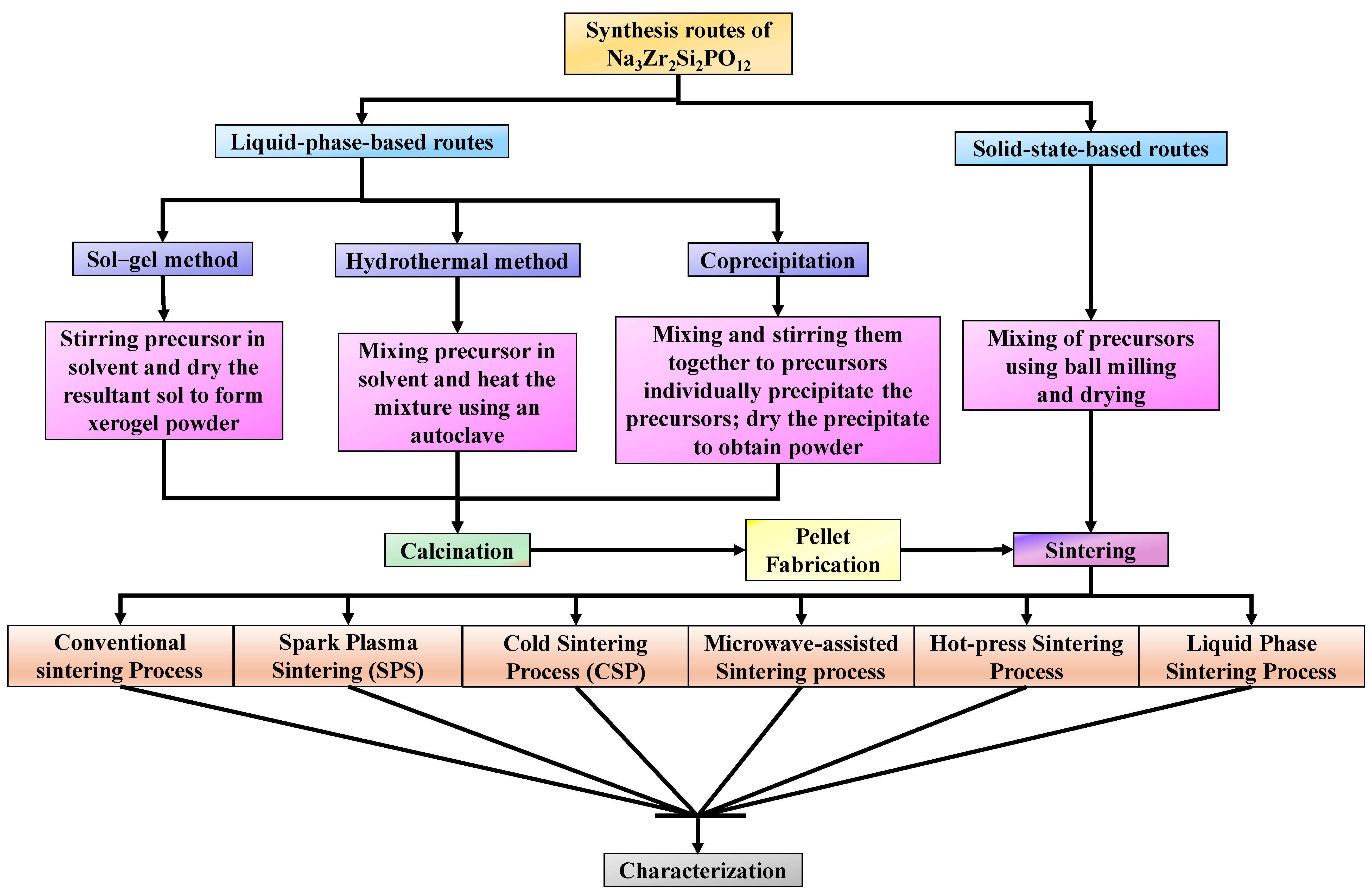
2.3. Synthesis Routes and Post-Processing of Na3Zr2Si2PO12
2.3.1. Liquid Phase Synthesis
- Sol–Gel Method
- b.
- Hydrothermal Method
- c.
- Coprecipitation Method
2.3.2. Solid State Synthesis
2.3.3. Sintering Techniques
- Spark Plasma Sintering (SPS)
- b.
- Hot Press Sintering
- c.
- Cold Sintering Process (CSP)
- d.
- Microwave-Assisted Sintering
- e.
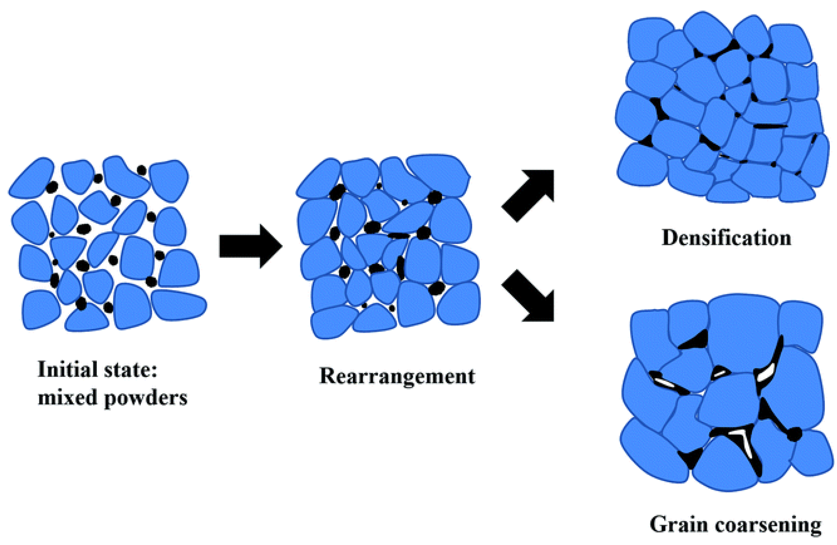
- Liquid Phase Sintering
2.4. Synthesis Factors Affecting the Properties of NASICON-Type Solid Electrolytes
2.4.1. Calcination
2.4.2. Bottleneck Size and Sodium-Ion Concentration
2.4.3. Chemical Substitutions and Doping Methods
2.5. Other Modified Composition of Na1+xZr2SixP3−xO12

| Year of Publishing | Chemical Formula | Substituting Ion | Synthetic Method | Ionic Conductivity [S/cm] at RT | Ref. |
|---|---|---|---|---|---|
| 2019 | Na3.2Zr1.9Ca0.1Si2PO12 | Ca2+ | Sol–gel | 1.67 × 10⁻³ | [82] |
| 2020 | Na3.2Zr1.9Mg0.1Si2PO12 | Mg2+ | Solid-state reaction | 2.2 × 10⁻³ | [83] |
| 2020 | Na3.4Zr1.9Zn0.1Si2.2P0.8O12 | Zn2+ | Solid-state reaction | 5.27 × 10⁻³ | [77] |
| 2020 | Na3Zr1.9Ce0.1Si2PO12 | Ce4+ | Liquid-feed flame spray | 6.9 × 10⁻⁴ | [84] |
| 2021 | Na3.3Zr1.7La0.3Si2PO12 | La3+ | Sol–gel | 1.34 × 10⁻³ | [85] |
| 2021 | Na3.4Sc0.4Zr1.6Si2PO12 | Sc3+ | Solid-state reaction | 2.6 × 10⁻³ | [86] |
| 2021 | Na3.1Zr1.9Ga0.1Si2PO12 | Ga3+ | Solid-state reaction | 1.06 × 10⁻³ | [87] |
| 2022 | Na3.2Zr1.8Pr0.2Si2PO12 | Pr3+ | Solid-state reaction | 1.27 × 10⁻³ | [88] |
| 2023 | Na3.4Zr1.6Sc0.4Si2PO12 | Sc3+ | Solid-state reaction | 1.77 × 10⁻³ | [89] |
| 2023 | Na3.2Zr1.8Tb0.2Si2PO12 | Tb3+ | Solid-state reaction | 6.32 × 10⁻⁴ | [90] |
| 2024 | Na3Zr1.92Ru0.08Si2PO12 | Ru3+ | Solid-state reaction | 8.1 × 10⁻⁴ | [81] |
| 2024 | Na3.5Zr1.75Mg0.25Si2PO12 | Mg2+ | Solid-state reaction | 2.4 × 10⁻³ | [91] |
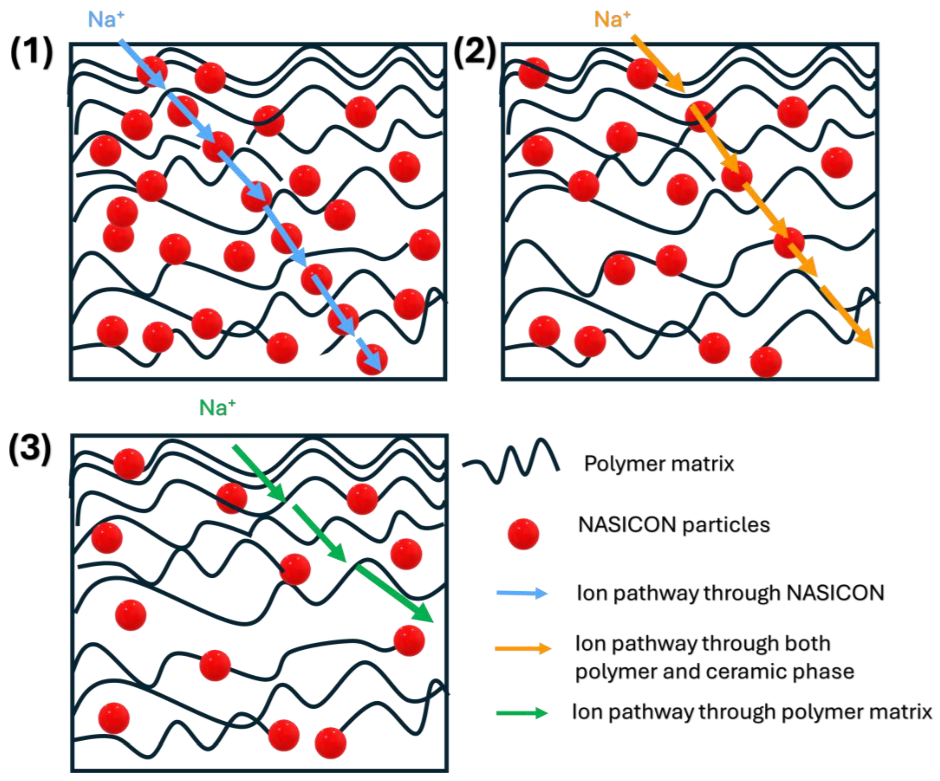
3. NASICON as a Filler in Composite Polymer Electrolytes
Sodium-Ion Conduction Mechanisms in CPE Caused by NASICON Incorporation
4. Effect of NASICON-Type Fillers on Various Properties of Composite Solid Electrolytes
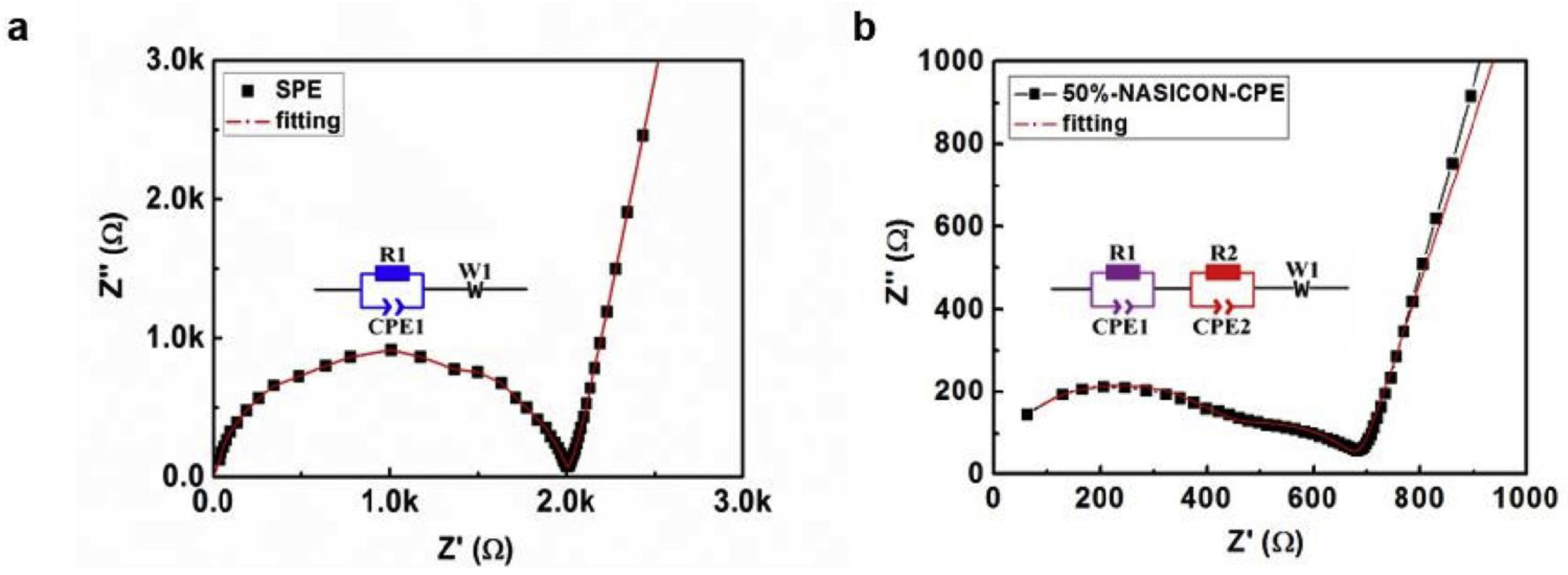
Electrochemical Performance Evaluation of NASICON-Based CPEs
5. Conclusions and Future Directions
Author Contributions
Funding
Data Availability Statement
Acknowledgments
Conflicts of Interest
Abbreviations
| C | Carbon |
| CEs | Composite Electrolytes |
| CPEs | Composite Polymer Electrolytes |
| CSP | Cold Sintering Process |
| CV | Cyclic Voltammetry |
| Ea | Activation Energy |
| EIS | Electrochemical Impedance Spectroscopy |
| EMI | Electromagnetic Interference |
| ESW | Electrochemical Stability Window |
| FAST | Field-Assisted Sintering Technology |
| IL | Ionic Liquid |
| ISEs | Inorganic Solid Electrolytes |
| LIBs | Lithium-Ion Batteries |
| LPS | Liquid-Phase Sintering |
| LSV | Linear Sweep Voltammetry |
| NaFSI | Sodium Bis(Fluorosulfonyl)Imide |
| NASICON | Na Super Ionic Conductor |
| NaTFSA | Sodium Trifluoro Methanesulfonate |
| NaTFSI | Sodium Bis(Trifluorosulfonyl) Imide |
| NTP | NaTi2(PO5)3 |
| NVP | Na3V2(PO4)3 |
| NZMSP | Na3.4Zr1.8Mg0.2Si2PO12 |
| NZSP | Na3Zr2Si2PO12 |
| PAN | Poly(Acrylonitrile) |
| PEO | Poly(Ethylene Oxide) |
| PFAS | Per- and polyfluoroalkyl substances |
| PLA | Poly(Lactic Acid) |
| PMMA | Poly(Methyl Methacrylate) |
| PVAc | Poly(Vinyl Acetate) |
| PVDF-HFP | Poly(Vinylidene Fluoride-Hexafluoropropylene |
| RT | Room Temperature |
| SEI | Solid Electrolyte Interphase |
| SEs | Solid Electrolytes |
| SIBs | Sodium-Ion Batteries |
| SL | Surface Layer |
| SPEs | Solid Polymer Electrolytes |
| SPS | Spark Plasma Sintering |
| SSEs | Solid-State Electrolytes |
| TGA | Thermogravimetric Analysis |
References
- Elalfy, D.A.; Gouda, E.; Kotb, M.F.; Bureš, V.; Sedhom, B.E. Comprehensive review of energy storage systems technologies, objectives, challenges, and future trends. Energy Strategy Rev. 2024, 54, 101482. [Google Scholar] [CrossRef]
- Zhao, L.; Zhang, T.; Li, W.; Li, T.; Zhang, L.; Zhang, X.; Wang, Z. Engineering of Sodium-Ion Batteries: Opportunities and Challenges. Engineering 2023, 24, 172–183. [Google Scholar] [CrossRef]
- Ahn, H.; Kim, D.; Lee, M.; Nam, K.W. Challenges and possibilities for aqueous battery systems. Commun. Mater. 2023, 4, 37. [Google Scholar] [CrossRef]
- Banik, T.; Bhattacharya, I.; Savunthari, K.V.; Mukerjee, S.; Adepoju, W.; Olatunji, A. Enhanced Performance of Sodium-Ion Battery Cathodes with Ti and V Co-Doped P2-Type Na0.67Fe0.5Mn0.5O2 Materials. Electrochem. 2024, 5, 437–454. [Google Scholar] [CrossRef]
- Darbar, D.; Reddy, M.V.; Bhattacharya, I. Understanding the Effect of Zn Doping on Stability of Cobalt-Free P2-Na0.60Fe0.5Mn0.5O2 Cathode for Sodium Ion Batteries. Electrochem. 2021, 2, 323–334. [Google Scholar] [CrossRef]
- Eftekhari, A. On the Theoretical Capacity/Energy of Lithium Batteries and Their Counterparts. ACS Sustain. Chem. Eng. 2019, 7, 3684–3687. [Google Scholar] [CrossRef]
- Thirupathi, R.; Kumari, V.; Chakrabarty, S.; Omar, S. Recent progress and prospects of NASICON framework electrodes for Na-ion batteries. Prog. Mater. Sci. 2023, 137, 101128. [Google Scholar] [CrossRef]
- Hayamizu, K.; Chiba, Y.; Haishi, T. Dynamic ionic radius of alkali metal ions in aqueous solution: A pulsed-field gradient NMR study. RSC Adv. 2021, 11, 20252–20257. [Google Scholar] [CrossRef]
- Nayak, P.K.; Yang, L.; Brehm, W.; Adelhelm, P. From Lithium-Ion to Sodium-Ion Batteries: Advantages, Challenges, and Surprises. Angew. Chem. Int. Ed. 2018, 57, 102–120. [Google Scholar] [CrossRef]
- Hua, Z. Comparative study of commercialized sodium-ion batteries and lithium-ion batteries. Appl. Comput. Eng. 2023, 26, 233–239. [Google Scholar] [CrossRef]
- Hu, J.; Liang, S.; Duan, H.; Tian, J.; Chen, S.; Dai, B.; Huang, C.; Liu, Y.; Lv, Y.; Wan, L.; et al. Cu-doped graphene Cu/N2OG: A high-performance alkaline metal ion battery anode with record-theoretical capacity. Appl. Surf. Sci. 2025, 682, 161752. [Google Scholar] [CrossRef]
- Hayyan, M.; Mjalli, F.S.; Hashim, M.A.; AlNashef, I.M.; Mei, T.X. Investigating the electrochemical windows of ionic liquids. J. Ind. Eng. Chem. 2013, 19, 106–112. [Google Scholar] [CrossRef]
- Mei, W.; Wang, X.; Wang, Y.; Chen, J.; Mao, Z.; Wang, D. Conductive Na3Sc2P3O12 filler with different crystal phases modified gel polymer electrolyte membranes for sodium ions batteries. J. Solid. State Chem. 2021, 302, 122459. [Google Scholar] [CrossRef]
- Hashimov, M.; Hofmann, A. Deciphering Electrolyte Degradation in Sodium-Based Batteries: The Role of Conductive Salt Source, Additives, and Storage Condition. Batteries 2023, 9, 530. [Google Scholar] [CrossRef]
- Rao, Y.B.; Bharathi, K.K.; Patro, L.N. Review on the synthesis and doping strategies in enhancing the Na ion conductivity of Na3Zr2Si2PO12 (NASICON) based solid electrolytes. Solid. State Ion. 2021, 366–367, 115671. [Google Scholar] [CrossRef]
- Xu, X.; Wang, Y.; Yi, Q.; Wang, X.; Camacho, R.A.P.; Kungl, H.; Eichel, R.A.; Lu, L.; Zhang, H. Ion Conduction in Composite Polymer Electrolytes: Potential Electrolytes for Sodium-Ion Batteries. ChemSusChem 2023, 16, e202202152. [Google Scholar] [CrossRef] [PubMed]
- Munir, T.; Tariq, A.; Shaheen, S.; Asghar, R.; Noor, R. Shifting trends: Exploring different polymer hosts and polyelectrolyte systems for efficient sodium-ion batteries. J. Energy Storage 2024, 98, 113045. [Google Scholar] [CrossRef]
- Hayashi, A.; Noi, K.; Sakuda, A.; Tatsumisago, M. Superionic glass-ceramic electrolytes for room-temperature rechargeable sodium batteries. Nat. Commun. 2012, 3, 856. [Google Scholar] [CrossRef]
- Karabelli, D.; Birke, K.P.; Weeber, M. A Performance and Cost Overview of Selected Solid-State Electrolytes: Race between Polymer Electrolytes and Inorganic Sulfide Electrolytes. Batteries 2021, 7, 18. [Google Scholar] [CrossRef]
- Park, J.; Son, J.P.; Ko, W.; Kim, J.-S.; Choi, Y.; Kim, H.; Kwak, H.; Seo, D.-H.; Kim, J.; Jung, Y.S. NaAlCl4: New Halide Solid Electrolyte for 3 V Stable Cost-Effective All-Solid-State Na-Ion Batteries. ACS Energy Lett. 2022, 7, 3293–3301. [Google Scholar] [CrossRef]
- Whittingham, M.S.; Huggins, R.A. Measurement of Sodium Ion Transport in Beta Alumina Using Reversible Solid Electrodes. J. Chem. Phys. 1971, 54, 414–416. [Google Scholar] [CrossRef]
- Li, C.; Li, R.; Liu, K.; Si, R.; Zhang, Z.; Hu, Y. NaSICON: A promising solid electrolyte for solid-state sodium batteries. Interdiscip. Mater. 2022, 1, 396–416. [Google Scholar] [CrossRef]
- Flor, G.; Marini, A.; Massarotti, V.; Villa, M. Reactivity of β-aluminas with water. Solid. State Ion. 1981, 2, 195–204. [Google Scholar] [CrossRef]
- Sudworth, J.L.; Barrow, P.; Dong, W.; Dunn, B.; Farrington, G.C.; Thomas, J.O. Toward Commercialization of the Beta-Alumina Family of Ionic Conductors. MRS Bull. 2000, 25, 22–26. [Google Scholar] [CrossRef]
- Wang, H.; Zhao, G.; Wang, S.; Liu, D.; Mei, Z.; An, Q.; Jiang, J.; Guo, H. Enhanced ionic conductivity of a Na3Zr2Si2PO12 solid electrolyte with Na2SiO3 obtained by liquid phase sintering for solid-state Na+ batteries. Nanoscale 2022, 14, 823–832. [Google Scholar] [CrossRef]
- Fu, C.; Li, Y.; Xu, W.; Feng, X.; Gu, W.; Liu, J.; Deng, W.; Wang, W.; Abeykoon, A.M.M.; Su, L.; et al. LaCl3-based sodium halide solid electrolytes with high ionic conductivity for all-solid-state batteries. Nat. Commun. 2024, 15, 4315. [Google Scholar] [CrossRef]
- Yu, S.; Kim, K.; Wood, B.C.; Jung, H.-G.; Chung, K.Y. Structural design strategies for superionic sodium halide solid electrolytes. J. Mater. Chem. A Mater. 2022, 10, 24301–24309. [Google Scholar] [CrossRef]
- Fritsch, C.; Hansen, A.-L.; Indris, S.; Knapp, M.; Ehrenberg, H. Mechanochemical synthesis of amorphous and crystalline Na2P2S6—Elucidation of local structural changes by X-ray total scattering and NMR. Dalton Trans. 2020, 49, 1668–1673. [Google Scholar] [CrossRef]
- Che, H.; Chen, S.; Xie, Y.; Wang, H.; Amine, K.; Liao, X.-Z.; Ma, Z.-F. Electrolyte design strategies and research progress for room-temperature sodium-ion batteries. Energy Environ. Sci. 2017, 10, 1075–1101. [Google Scholar] [CrossRef]
- Menon, N.H.; Sabu, A.; Ramanujam, B.T.S. Polyvinylidene fluoride-poly(vinyl acetate)-natural graphite blend nanocomposites: Investigations of electroactive phase formation, electrical, thermal, and wetting properties. Polym. Adv. Technol. 2022, 33, 4023–4040. [Google Scholar] [CrossRef]
- Sabu, A.; Annamalai, P.K.; Raghava, R.B.T.S. Tailoring electromagnetic interference shielding, electrical and thermal properties of poly(vinylidene fluoride) based hybrid nanocomposites with carbon nanofiber and magnetite nanoparticles. J. Mater. Chem. C Mater. 2025, 13, 1982–1998. [Google Scholar] [CrossRef]
- Liu, Z.; Shikinaka, K.; Otsuka, Y.; Tominaga, Y. Enhanced ionic conduction in composite polymer electrolytes filled with plant biomass “lignin”. Chem. Commun. 2022, 58, 4504–4507. [Google Scholar] [CrossRef] [PubMed]
- Balakrishnan, K.P.; Senthilkumar, K.K.; Gokila, N.; Thangavelu, R.K.R.; Annamalai, P.K.; Raghava, R.B.T.S. Surfactant assisted tuning of electrical conductivity, electromagnetic interference shielding effectiveness, wetting properties of poly(lactic acid)-expanded graphite-magnetite nanocube hybrid bio-nanocomposites. Eur. Polym. J. 2024, 214, 113135. [Google Scholar] [CrossRef]
- Savvidou, E.K.; Rensmo, A.; Benskin, J.P.; Schellenberger, S.; Hu, X.; Weil, M.; Cousins, I.T. PFAS-Free Energy Storage: Investigating Alternatives for Lithium-Ion Batteries. Environ. Sci. Technol. 2024, 58, 21908–21917. [Google Scholar] [CrossRef] [PubMed]
- Chew, K.W.; Ng, T.C.; How, Z.H. Conductivity and Microstructure Study of PLA-Based Polymer Electrolyte Salted with Lithium Perchloride, LiClO4. Int. J. Electrochem. Sci. 2013, 8, 6354–6364. [Google Scholar] [CrossRef]
- Bonizzoni, S.; Ferrara, C.; Berbenni, V.; Anselmi-Tamburini, U.; Mustarelli, P.; Tealdi, C. NASICON-type polymer-in-ceramic composite electrolytes for lithium batteries. Phys. Chem. Chem. Phys. 2019, 21, 6142–6149. [Google Scholar] [CrossRef]
- Anantharamulu, N.; Rao, K.K.; Rambabu, G.; Kumar, B.V.; Radha, V.; Vithal, M. A wide-ranging review on Nasicon type materials. J. Mater. Sci. 2011, 46, 2821–2837. [Google Scholar] [CrossRef]
- Singh, K.; Chakraborty, A.; Thirupathi, R.; Omar, S. Recent advances in NASICON-type oxide electrolytes for solid-state sodium-ion rechargeable batteries. Ionics 2022, 28, 5289–5319. [Google Scholar] [CrossRef]
- Cui, Z.; Sun, S.; Ning, G.; Liang, L.; Wang, Z.; Qiao, J.; Zhang, L.; Chen, J.; Zhang, Z. Advances in the application of first principles calculations to phosphate-based NASICON battery materials. J. Mater. Chem. A Mater. 2024, 12, 29335–29354. [Google Scholar] [CrossRef]
- Rizvi, S.; Aladhyani, I.; Ding, Y.; Zhang, Q. Recent advances in doping Na3Zr2Si2PO12 (NASICON) solid-state electrolyte for sodium-ion batteries. Nano Energy 2024, 129, 110009. [Google Scholar] [CrossRef]
- Choo, Y.; Halat, D.M.; Villaluenga, I.; Timachova, K.; Balsara, N.P. Diffusion and migration in polymer electrolytes. Prog. Polym. Sci. 2020, 103, 101220. [Google Scholar] [CrossRef]
- Stenina, I.; Novikova, S.; Voropaeva, D.; Yaroslavtsev, A. Solid Electrolytes Based on NASICON-Structured Phosphates for Lithium Metal Batteries. Batteries 2023, 9, 407. [Google Scholar] [CrossRef]
- Samiee, M.; Radhakrishnan, B.; Rice, Z.; Deng, Z.; Meng, Y.S.; Ong, S.P.; Luo, J. Divalent-doped Na3Zr2Si2PO12 natrium superionic conductor: Improving the ionic conductivity via simultaneously optimizing the phase and chemistry of the primary and secondary phases. J. Power Sources 2017, 347, 229–237. [Google Scholar] [CrossRef]
- Rosen, M.; Mahioui, S.; Schwab, C.; Dück, G.; Finsterbusch, M. Tape Casting of NASICON-Based Separators with High Conductivity for Na All-Solid-State Batteries. Electrochem. 2025, 6, 5. [Google Scholar] [CrossRef]
- Yang, Z.; Tang, B.; Xie, Z.; Zhou, Z. NASICON-Type Na3Zr2Si2PO12 Solid-State Electrolytes for Sodium Batteries. ChemElectroChem 2021, 8, 1035–1047. [Google Scholar] [CrossRef]
- Park, H.; Jung, K.; Nezafati, M.; Kim, C.-S.; Kang, B. Sodium Ion Diffusion in Nasicon (Na3Zr2Si2PO12) Solid Electrolytes: Effects of Excess Sodium. ACS Appl. Mater. Interfaces 2016, 8, 27814–27824. [Google Scholar] [CrossRef] [PubMed]
- Liu, L.; Liang, D.; Zhou, X.; Liu, Y.; Su, J.; Xu, Y.; Peng, J. Enhancing Na-ion conducting capacity of NASICON ceramic electrolyte Na3.4Zr2Si2.4P0.6O12 by NaF sintering aid. J. Mater. Sci. 2022, 57, 11774–11782. [Google Scholar] [CrossRef]
- Chen, S.; Wu, C.; Shen, L.; Zhu, C.; Huang, Y.; Xi, K.; Maier, J.; Yu, Y. Challenges and Perspectives for NASICON-Type Electrode Materials for Advanced Sodium-Ion Batteries. Adv. Mater. 2017, 29, 1700431. [Google Scholar] [CrossRef]
- Yang, J.; Wan, H.-L.; Zhang, Z.-H.; Liu, G.-Z.; Xu, X.-X.; Hu, Y.-S.; Yao, X.-Y. NASICON-structured Na3.1Zr1.95Mg0.05Si2PO12 solid electrolyte for solid-state sodium batteries. Rare Met. 2018, 37, 480–487. [Google Scholar] [CrossRef]
- Zhang, Z.; Wenzel, S.; Zhu, Y.; Sann, J.; Shen, L.; Yang, J.; Yao, X.; Hu, Y.-S.; Wolverton, C.; Li, H.; et al. Na3Zr2Si2PO12: A Stable Na+-Ion Solid Electrolyte for Solid-State Batteries. ACS Appl. Energy Mater. 2020, 3, 7427–7437. [Google Scholar] [CrossRef]
- Lu, Y.; Li, L.; Zhang, Q.; Niu, Z.; Chen, J. Electrolyte and Interface Engineering for Solid-State Sodium Batteries. Joule 2018, 2, 1747–1770. [Google Scholar] [CrossRef]
- Jolley, A.G.; Taylor, D.D.; Schreiber, N.J.; Wachsman, E.D. Structural Investigation of Monoclinic-Rhombohedral Phase Transition in Na3Zr2Si2PO12 and Doped NASICON. J. Am. Ceram. Soc. 2015, 98, 2902–2907. [Google Scholar] [CrossRef]
- Jolley, A.G.; Cohn, G.; Hitz, G.T.; Wachsman, E.D. Improving the ionic conductivity of NASICON through aliovalent cation substitution of Na3Zr2Si2PO12. Ionics 2015, 21, 3031–3038. [Google Scholar] [CrossRef]
- Ortiz-Mosquera, J.F.; Nieto-Muñoz, A.M.; Rodrigues, A.C.M. New Na1+xGe2(SiO4)x(PO4)3–x NASICON Series with Improved Grain and Grain Boundary Conductivities. ACS Appl. Mater. Interfaces 2020, 12, 13914–13922. [Google Scholar] [CrossRef] [PubMed]
- Ignaszak, A.; Pasierb, P.; Gajerski, R.; Komornicki, S. Synthesis and properties of Nasicon-type materials. Thermochim. Acta 2005, 426, 7–14. [Google Scholar] [CrossRef]
- Liu, L.; Jia, X.; Yang, Q.; Huang, S.; Ke, L.; Yang, J.; Kitipornchai, S. Optimisation of properties of multidimensional hybrid polymer nanocomposites for flexible pressure sensors. Chem. Eng. J. 2024, 493, 152705. [Google Scholar] [CrossRef]
- Narayanan, S.; Reid, S.; Butler, S.; Thangadurai, V. Sintering temperature, excess sodium, and phosphorous dependencies on morphology and ionic conductivity of NASICON Na3Zr2Si2PO12. Solid. State Ion. 2019, 331, 22–29. [Google Scholar] [CrossRef]
- Niazmand, M.; Khakpour, Z.; Mortazavi, A. Electrochemical properties of nanostructure NASICON synthesized by chemical routes: A comparison between coprecipitation and sol-gel. J. Alloys Compd. 2019, 798, 311–319. [Google Scholar] [CrossRef]
- Oh, J.A.S.; He, L.; Plewa, A.; Morita, M.; Zhao, Y.; Sakamoto, T.; Song, X.; Zhai, W.; Zeng, K.; Lu, L. Composite NASICON (Na3Zr2Si2PO12) Solid-State Electrolyte with Enhanced Na+ Ionic Conductivity: Effect of Liquid Phase Sintering. ACS Appl. Mater. Interfaces 2019, 11, 40125–40133. [Google Scholar] [CrossRef] [PubMed]
- Essoumhi, A.; Favotto, C.; Mansori, M.; Satre, P. Synthesis and characterization of a NaSICON series with general formula Na2.8Zr2−ySi1.8−4yP1.2+4yO12 (0⩽y⩽0.45). J. Solid. State Chem. 2004, 177, 4475–4481. [Google Scholar] [CrossRef]
- Shimanouchi-Futagami, R.; Nishimori, M.; Nishizawa, H. Hydrothermal synthesis and electric conductivity of the NASICON-related solid solution, Na1+2xTi2BxP3−xO12. J. Mater. Sci. Lett. 2000, 19, 405–407. [Google Scholar] [CrossRef]
- Yao, Z.; Zhu, K.J.; Zhu, K.; Zhang, J.; Li, X.; Chen, J.; Wang, J.; Yan, K.; Liu, J. Co-Precipitation Synthesis and Electrochemical Properties of NASICON-Type Li1.3Al0.3Ti1.7(PO4)3 Solid Electrolytes. J. Mater. Sci. Mater. Electron. 2021, 32, 24834–24844. [Google Scholar] [CrossRef]
- Bader, N.; Zimmermann, B. Co-precipitation as a sample preparation technique for trace element analysis: An overview. Int. J. Chem. Sci. 2014, 12, 519–525. [Google Scholar]
- Jalalian-Khakshour, A.; Phillips, C.O.; Jackson, L.; Dunlop, T.O.; Margadonna, S.; Deganello, D. Solid-state synthesis of NASICON (Na3Zr2Si2PO12) using nanoparticle precursors for optimisation of ionic conductivity. J. Mater. Sci. 2020, 55, 2291–2302. [Google Scholar] [CrossRef]
- Wang, B.; Wang, J.; Chang, A.; Yao, J. Bismuth trioxide-tailored sintering temperature, microstructure and NTCR characteristics of Mn1.1Co1.5Fe0.4O4 ceramics. RSC Adv. 2019, 9, 25488–25495. [Google Scholar] [CrossRef] [PubMed]
- da Silva, J.G.P.; Bram, M.; Laptev, A.M.; Gonzalez-Julian, J.; Ma, Q.; Tietz, F.; Guillon, O. Sintering of a sodium-based NASICON electrolyte: A comparative study between cold, field assisted and conventional sintering methods. J. Eur. Ceram. Soc. 2019, 39, 2697–2702. [Google Scholar] [CrossRef]
- Yu, T.; Cheng, J.; Li, L.; Sun, B.; Bao, X.; Zhang, H. Current understanding and applications of the cold sintering process. Front. Chem. Sci. Eng. 2019, 13, 654–664. [Google Scholar] [CrossRef]
- Lee, J.; Chang, C.; Lee, Y.I.L.; Lee, J.; Hong, S. Spark Plasma Sintering (SPS) of NASICON Ceramics. J. Am. Ceram. Soc. 2004, 87, 305–307. [Google Scholar] [CrossRef]
- Miura, N.; Ono, M.; Shimanoe, K.; Yamazoe, N. A compact solid-state amperometric sensor for detection of NO2 in ppb range. Sens. Actuators B Chem. 1998, 49, 101–109. [Google Scholar] [CrossRef]
- Fuentes, R.O.; Marques, F.M.B.; Franco, J.I. Synthesis and properties of NASICON prepared from different zirconia-based precursors. Bol. Soc. Esp. Cerám. Vidr. 1999, 38, 631–634. [Google Scholar] [CrossRef]
- Kimura, M.; Tseng, K.-T.; Wolfenstine, J.; Sakamoto, J. The use of hot-pressing to reduce grain boundary resistance in Nasicon of nominal composition Na3Zr2Si2PO12. Solid. State Ion. 2024, 411, 116561. [Google Scholar] [CrossRef]
- Grady, Z.; Fan, Z.; Ndayishimiye, A.; Randall, C.A. Design and Sintering of All-Solid-State Composite Cathodes with Tunable Mixed Conduction Properties via the Cold Sintering Process. ACS Appl. Mater. Interfaces 2021, 13, 48071–48087. [Google Scholar] [CrossRef]
- Wang, X.; Liu, Z.; Tang, Y.; Chen, J.; Wang, D.; Mao, Z. Low temperature and rapid microwave sintering of Na3Zr2Si2PO12 solid electrolytes for Na-Ion batteries. J. Power Sources 2021, 481, 228924. [Google Scholar] [CrossRef]
- Ruan, Y.; Song, S.; Liu, J.; Liu, P.; Cheng, B.; Song, X.; Battaglia, V. Improved structural stability and ionic conductivity of Na3Zr2Si2PO12 solid electrolyte by rare earth metal substitutions. Ceram. Int. 2017, 43, 7810–7815. [Google Scholar] [CrossRef]
- Song, S.; Duong, H.M.; Korsunsky, A.M.; Hu, N.; Lu, L. A Na+ Superionic Conductor for Room-Temperature Sodium Batteries. Sci. Rep. 2016, 6, 32330. [Google Scholar] [CrossRef] [PubMed]
- Yang, J.; Liu, G.; Avdeev, M.; Wan, H.; Han, F.; Shen, L.; Zou, Z.; Shi, S.; Hu, Y.-S.; Wang, C.; et al. Ultrastable All-Solid-State Sodium Rechargeable Batteries. ACS Energy Lett. 2020, 5, 2835–2841. [Google Scholar] [CrossRef]
- Wang, J.; He, T.; Yang, X.; Cai, Z.; Wang, Y.; Lacivita, V.; Kim, H.; Ouyang, B.; Ceder, G. Design principles for NASICON super-ionic conductors. Nat. Commun. 2023, 14, 5210. [Google Scholar] [CrossRef]
- Jang, I.-S.; Go, W.; Song, B.-Y.; Park, H.; Kang, Y.C.; Chun, J. Improving ionic conductivity of von-Alpen-type NASICON ceramic electrolytes via magnesium doping. J. Adv. Ceram. 2023, 12, 1058–1066. [Google Scholar] [CrossRef]
- Ma, Q.; Guin, M.; Naqash, S.; Tsai, C.-L.; Tietz, F.; Guillon, O. Scandium-Substituted Na3Zr2(SiO4)2PO4 ) Prepared by a Solution-Assisted Solid-State Reaction Method as Sodium-Ion Conductors. Chem. Mater. 2016, 28, 4821–4828. [Google Scholar] [CrossRef]
- Liu, Y.; Liu, L.; Peng, J.; Zhou, X.; Liang, D.; Zhao, L.; Su, J.; Zhang, B.; Li, S.; Zhang, N.; et al. A niobium-substituted sodium superionic conductor with conductivity higher than 5.5 mS cm−1 prepared by solution-assisted solid-state reaction method. J. Power Sources 2022, 518, 230765. [Google Scholar] [CrossRef]
- Singh, M.D.; Gorai, D.K.; Brajesh, K.; Singh, P.; Ranawade, V.; Shinde, A.V.; Jareer, M.; Gupta, R.; Garg, A.; Agarwal, V.; et al. Ruthenium doping of NASICON electrolyte augments the performance of solid-state sodium-ion batteries. Chem. Eng. J. 2024, 489, 151330. [Google Scholar] [CrossRef]
- Lu, Y.; Alonso, J.A.; Yi, Q.; Lu, L.; Wang, Z.L.; Sun, C. A High-Performance Monolithic Solid-State Sodium Battery with Ca2+ Doped Na3Zr2Si2PO12 Electrolyte. Adv. Energy Mater. 2019, 9, 1901205. [Google Scholar] [CrossRef]
- He, S.; Xu, Y.; Ma, X.; Chen, Y.; Lin, J.; Wang, C. Mg2+/F− Synergy to Enhance the Ionic Conductivity of Na3Zr2Si2PO12 Solid Electrolyte for Solid-State Sodium Batteries. ChemElectroChem 2020, 7, 2087–2094. [Google Scholar] [CrossRef]
- Liu, S.; Zhou, C.; Wang, Y.; Wang, W.; Pei, Y.; Kieffer, J.; Laine, R.M. Ce-Substituted Nanograin Na3Zr2Si2PO12 Prepared by LF-FSP as Sodium-Ion Conductors. ACS Appl. Mater. Interfaces 2020, 12, 3502–3509. [Google Scholar] [CrossRef]
- Sun, F.; Xiang, Y.; Sun, Q.; Zhong, G.; Banis, M.N.; Li, W.; Liu, Y.; Luo, J.; Li, R.; Fu, R.; et al. Insight into Ion Diffusion Dynamics/Mechanisms and Electronic Structure of Highly Conductive Sodium-Rich Na3+ xLaxZr2– xSi2PO12 (0 ≤ x ≤ 0.5) Solid-State Electrolytes. ACS Appl. Mater. Interfaces 2021, 13, 13132–13138. [Google Scholar] [CrossRef]
- Santhoshkumar, B.; Khanna, D.L.R.; Choudhary, M.B.; Rao, P.L.; Ramanathan, K.V.; Bera, A.K.; Yusuf, S.M.; Pahari, B. Improved ionic conductivity of Na3+xScxZr2-xSi2PO12 (x = 0.2, 0.3, 0.4, 0.5) NASICON via optimized sintering conditions: Investigation of crystal structure, local atomic structure, and microstructure. Chem. Phys. Lett. 2021, 776, 138706. [Google Scholar] [CrossRef]
- Huang, C.; Yang, G.; Yu, W.; Xue, C.; Zhai, Y.; Tang, W.; Hu, N.; Wen, Z.; Lu, L.; Song, S. Gallium-substituted Nasicon Na3Zr2Si2PO12 solid electrolytes. J. Alloys Compd. 2021, 855, 157501. [Google Scholar] [CrossRef]
- Wang, X.; Chen, J.; Mao, Z.; Wang, D. Effective resistance to dendrite growth of NASICON solid electrolyte with lower electronic conductivity. Chem. Eng. J. 2022, 427, 130899. [Google Scholar] [CrossRef]
- Wang, Q.; Yu, C.; Li, L.; Liu, X.; Zhang, X.; Gao, G.; Wang, Y.; Li, G. Sc-doping in Na3Zr2Si2PO12 electrolytes enables preeminent performance of solid-state sodium batteries in a wide temperature range. Energy Storage Mater. 2023, 54, 135–145. [Google Scholar] [CrossRef]
- Wen, C.; Luo, Z.; Liu, X.; Wu, Y.; Tong, J.; Liang, H.; Zhang, Q.; Ning, T.; Lu, A. Enhanced electrochemical properties of NASICON-type Na3Zr2Si2PO12 solid electrolytes with Tb3+-ions-assisted sintering. Solid. State Ion. 2023, 393, 116185. [Google Scholar] [CrossRef]
- Wang, J.; Kang, J.; Guo, X.; Hu, S.; Tang, Y.; Jin, L.; Wei, X. Enhanced ionic conductivity in Na3Zr2Si2PO12 NASICON-type solid electrolytes by adding Mg2+-ions. J. Alloys Compd. 2024, 988, 174327. [Google Scholar] [CrossRef]
- Maurya, D.K.; Dhanusuraman, R.; Guo, Z.; Angaiah, S. Composite polymer electrolytes: Progress, challenges, and future outlook for sodium-ion batteries. Adv. Compos. Hybrid. Mater. 2022, 5, 2651–2674. [Google Scholar] [CrossRef]
- Wang, S.; La Monaca, A.; Demopoulos, G.P. Composite solid-state electrolytes for all solid-state lithium batteries: Progress, challenges and outlook. Energy Adv. 2025, 4, 11–36. [Google Scholar] [CrossRef]
- Singh, M.D.; Dalvi, A. Novel hybrid composites NaCF3SO3–PEO–NASICON for sodium ion battery applications. AIP Conf. Proc. 2019, 2115, 030565. [Google Scholar] [CrossRef]
- Salgueiro, T.A.; Veloso, R.C.; Ventura, J.; Danzi, F.; Oliveira, J. Ionic Conductivity Analysis of NASICON Solid Electrolyte Coated with Polyvinyl-Based Polymers. Batteries 2024, 10, 157. [Google Scholar] [CrossRef]
- Shen, L.; Deng, S.; Jiang, R.; Liu, G.; Yang, J.; Yao, X. Flexible composite solid electrolyte with 80 wt% Na3.4Zr1.9Zn0.1Si2.2P0.8O12 for solid-state sodium batteries. Energy Storage Mater. 2022, 46, 175–181. [Google Scholar] [CrossRef]
- Wang, Y.; Wang, Z.; Sun, J.; Zheng, F.; Kotobuki, M.; Wu, T.; Zeng, K.; Lu, L. Flexible, stable, fast-ion-conducting composite electrolyte composed of nanostructured Na-super-ion-conductor framework and continuous Poly(ethylene oxide) for all-solid-state Na battery. J. Power Sources 2020, 454, 227949. [Google Scholar] [CrossRef]
- Li, Z.-Y.; Li, Z.; Fu, J.-L.; Guo, X. Sodium-ion conducting polymer electrolytes. Rare Metals 2023, 42, 1–16. [Google Scholar] [CrossRef]
- Kim, J.-K.; Lim, Y.J.; Kim, H.; Cho, G.-B.; Kim, Y. A hybrid solid electrolyte for flexible solid-state sodium batteries. Energy Environ. Sci. 2015, 8, 3589–3596. [Google Scholar] [CrossRef]
- Zhang, Z.; Xu, K.; Rong, X.; Hu, Y.-S.; Li, H.; Huang, X.; Chen, L. Na3.4Zr1.8Mg0.2Si2PO12 filled poly(ethylene oxide)/Na(CF3SO2)2N as flexible composite polymer electrolyte for solid-state sodium batteries. J. Power Sources 2017, 372, 270–275. [Google Scholar] [CrossRef]
- Niu, W.; Chen, L.; Liu, Y.; Fan, L.-Z. All-solid-state sodium batteries enabled by flexible composite electrolytes and plastic-crystal interphase. Chem. Eng. J. 2020, 384, 123233. [Google Scholar] [CrossRef]
- Zhang, Z.; Zhang, Q.; Ren, C.; Luo, F.; Ma, Q.; Hu, Y.-S.; Zhou, Z.; Li, H.; Huang, X.; Chen, L. A ceramic/polymer composite solid electrolyte for sodium batteries. J. Mater. Chem. A Mater. 2016, 4, 15823–15828. [Google Scholar] [CrossRef]
- Yu, X.; Xue, L.; Goodenough, J.B.; Manthiram, A. A High-Performance All-Solid-State Sodium Battery with a Poly(ethylene oxide)–Na3Zr2Si2PO12 Composite Electrolyte. ACS Mater. Lett. 2019, 1, 132–138. [Google Scholar] [CrossRef]
- Wu, J.-F.; Yu, Z.-Y.; Wang, Q.; Guo, X. High performance all-solid-state sodium batteries actualized by polyethylene oxide/Na2Zn2TeO6 composite solid electrolytes. Energy Storage Mater. 2020, 24, 467–471. [Google Scholar] [CrossRef]
- Hiraoka, K.; Kato, M.; Kobayashi, T.; Seki, S. Polyether/Na3Zr2Si2PO12 Composite Solid Electrolytes for All-Solid-State Sodium Batteries. J. Phys. Chem. C 2020, 124, 21948–21956. [Google Scholar] [CrossRef]
- Cheng, M.; Qu, T.; Zi, J.; Yao, Y.; Liang, F.; Ma, W.; Yang, B.; Dai, Y.; Lei, Y. A hybrid solid electrolyte for solid-state sodium ion batteries with good cycle performance. Nanotechnology 2020, 31, 425401. [Google Scholar] [CrossRef] [PubMed]


| Element | Ionic Radii (pm) | Theoretical Specific Energy Density (Wh/kg) |
|---|---|---|
| Lithium (Li) | 71 | 285 |
| Sodium (Na) | 97 | 160 |
| Potassium (K) | 141 | 150 |
| Chemical Formula | Ionic Conductivity [S/cm] at RT | Reference |
|---|---|---|
| NASICON | ~10−3 | [25] |
| Na0.7La0.7Zr0.3Cl4 | 2.9 × 10⁻⁴ | [26] |
| Na3MI6 | ~10−4 | [27] |
| Na3PS4 | 2 × 10⁻⁴ | [18] |
| Amorphous Na2P2S6 | 5.7 × 10⁻⁸ | [28] |
| Crystalline Na2P2S6 | 2.6 × 10⁻¹¹ | [28] |
| Polymer and Sodium Salt | NASICON type | Ionic Conductivity S/cm | Electrochemical Performance | Ref. | |
|---|---|---|---|---|---|
| 1 | PEO and sodium bis(trifluoromethanesulfonyl)imide (Na(CF3SO2)2N) | Na3.4Zr1.8Mg0.2Si2PO12 (50 wt.%) | 2.8 × 10⁻³ (at 80 °C) | With Na3V2(PO4)3; Na as the electrode showed a 115.9 mAh/g and 107 mAh/g charge and discharge capacity at a 0.1 C rate with 4.3 V ESW and a 98.6% Coulombic efficiency. | [100] |
| 2 | PEO and sodium bis(fluoro sulfonyl)imide (NaFSI) | Na3.4Zr1.8Mg0.2Si2PO12 (NZMSP) (40 wt.%) | 4.4 × 10⁻⁵ (at RT) | With Na3V2(PO4)3; Na as the electrodes showed a 106.1 mAh/g charge capacity at a 0.1 C rate with >5 V ESW and a 94% Coulombic efficiency. | [102] |
| 3 | PVDF–HFP (binder) and sodium triflate (NaSO3CF3) | Na3Zr2Si2PO12 (70 wt.%) | 1.4 × 10⁻³ (at 90 °C) | With NaFePO4; HC as the electrodes showed a 330 mAh/g discharge capacity at a 0.2 C rate. | [99] |
| 4 | PEO and sodium perchlorate (NaClO4) | Na3Zr2Si2PO12 (25 wt.%) | 5.6 × 10⁻⁴ (at 60 °C) | With Na2MnFe(CN)6; Na as the electrode showed a 111 mAh/g and 109 mAh/g charge and discharge capacity at a 0.5 C rate with a 97% Coulombic efficiency and 83% capacity retention over 300 cycles. | [103] |
| 5 | PEO and sodium bis(trifluoro methanesulfonyl)imide (NaTFSI) | Na2Zn2TeO6 (50 wt.%) | 4 × 10⁻⁵ (at 30 °C) | With Na3V2(PO4)3; Na as the electrode showed a 106 mAh/g discharge capacity at a 0.2 C rate with a 4 V ESW. | [104] |
| 6 |
PE-based macromonomer and sodium srifluoro methanesulfonate (NaTFSA) |
Na3Zr2Si2PO12 (30 wt.%) |
1.03 × 10⁻⁵ (at RT) | With NaCoO2; Na as the electrodes showed a 115.9 mAh/g and a 107 mAh/g charge and discharge capacity at a 0.1 C rate with a 4.3 V ESW and a 98.6% Coulombic efficiency. | [105] |
| 7 | PEO and sodium bis(trifluoro methanesulfonyl)imide (NaTFSI) |
Na3Zr2Si2PO12 (10 wt.%) | 1.4 × 10⁻⁴ (at RT) | With a loading of 25 wt.% filler in CPE; Na3V2(PO4)3 and Na as electrodes showed a 96.2 mAh/g discharge capacity at a 0.1 C rate with a 4 V ESW and a 98% Coulombic efficiency. | [97] |
| 8 |
PVDF-HFP and sodium perchlorate (NaClO4) | Na3Zr2Si2PO12 (10 wt.%) |
2.25 × 10⁻³ (at RT) | With Na3V2(PO4)3; Na as the electrode showed a 98 mAh/g reversible capacity at a 0.2 C rate with a 5 V ESW and a 62.7% Coulombic efficiency | [106] |
Disclaimer/Publisher’s Note: The statements, opinions and data contained in all publications are solely those of the individual author(s) and contributor(s) and not of MDPI and/or the editor(s). MDPI and/or the editor(s) disclaim responsibility for any injury to people or property resulting from any ideas, methods, instructions or products referred to in the content. |
© 2025 by the authors. Licensee MDPI, Basel, Switzerland. This article is an open access article distributed under the terms and conditions of the Creative Commons Attribution (CC BY) license (https://creativecommons.org/licenses/by/4.0/).
Share and Cite
Senthilkumar, K.K.; Thiruvengadathan, R.; Raghava, R.B.T.S. Recent Advancements in Na Super Ionic Conductor-Incorporated Composite Polymer Electrolytes for Sodium-Ion Battery Application. Electrochem 2025, 6, 6. https://doi.org/10.3390/electrochem6010006
Senthilkumar KK, Thiruvengadathan R, Raghava RBTS. Recent Advancements in Na Super Ionic Conductor-Incorporated Composite Polymer Electrolytes for Sodium-Ion Battery Application. Electrochem. 2025; 6(1):6. https://doi.org/10.3390/electrochem6010006
Chicago/Turabian StyleSenthilkumar, Kanya Koothanatham, Rajagopalan Thiruvengadathan, and Ramanujam Brahmadesam Thoopul Srinivasa Raghava. 2025. "Recent Advancements in Na Super Ionic Conductor-Incorporated Composite Polymer Electrolytes for Sodium-Ion Battery Application" Electrochem 6, no. 1: 6. https://doi.org/10.3390/electrochem6010006
APA StyleSenthilkumar, K. K., Thiruvengadathan, R., & Raghava, R. B. T. S. (2025). Recent Advancements in Na Super Ionic Conductor-Incorporated Composite Polymer Electrolytes for Sodium-Ion Battery Application. Electrochem, 6(1), 6. https://doi.org/10.3390/electrochem6010006