Article

The Method of Cleaning Cutting Fluid Using Ultrasonic Treatment

by
Anna Kim
1,
Adil Kadyrov
1,*,
Kirill Sinelnikov
1,
Karibek Sherov
2 and
Vassiliy Yurchenko
1
1
Department of Technological Equipment, Mechanical Engineering and Standardization, Abylkas Saginov Karaganda Technical University, Karaganda 100012, Kazakhstan
2
Department of Technological Machines and Equipment, S. Seifullin Kazakh Agro Technical Research University, Astana 010011, Kazakhstan
*
Author to whom correspondence should be addressed.
Appl. Mech. 2025, 6(4), 83; https://doi.org/10.3390/applmech6040083 (registering DOI)
Submission received: 6 September 2025 / Revised: 9 November 2025 / Accepted: 13 November 2025 / Published: 18 November 2025

Abstract

Cutting fluids are widely used in mechanical engineering to reduce friction and heat generation during metal machining. However, during operation, these fluids become contaminated with metal particles, dust, and microorganisms, leading to degradation of their functional properties and environmental concerns. This study investigates the ultrasonic cleaning and regeneration of contaminated cutting fluids. A rheological model of the elastic–viscous medium was analyzed, and a physical model describing the ultrasonic cleaning mechanism was proposed. Experimental investigations were conducted to validate the theoretical assumptions. The results confirmed that ultrasonic treatment promotes dispersion and phase separation of the fluid, removes putrefactive odor, and partially destroys microorganisms. The regenerated fluid exhibited enhanced clarity and stability compared with the contaminated samples. The findings contribute to a deeper understanding of the physicochemical processes occurring during ultrasonic treatment and demonstrate the potential of this method for sustainable reuse of cutting fluids in industrial applications.

1. Introduction

Cutting fluids play a crucial role in mechanical engineering, particularly in metal machining processes [1,2,3]. The primary purpose of using cutting fluid is to reduce friction between the workpiece and the cutting tool, thereby minimizing deformation of the workpiece during processing, increasing the service life of the cutting tool, and ultimately enhancing productivity in metalworking [4,5,6,7,8,9,10,11,12].
Depending on the machining method and intended application, metalworking fluids can be classified as follows:
-
Water-miscible and water-immiscible cutting fluids;
-
Emulsifiers and oil-based fluids for lubrication and cooling;
-
Synthetic, semi-synthetic, and fast-evaporating formulations [1,13,14,15].
At present, new types of metalworking fluids [16] based on biodegradable materials [17,18,19,20,21,22,23] are being developed; however, they have not gained widespread use due to their high production cost.
The machining process is accompanied by the formation of various contaminants, including oil mist, fine aerosols, vapors, smoke, unpleasant and harmful odors, metal dust, and shavings. The service life of cutting fluid solutions typically ranges from 2 weeks to 3–6 months. After this period, if the cutting fluid (emulsion) is not subjected to proper treatment or regeneration during operation, it is discarded and sent for decontamination and disposal using expensive technologies. Therefore, the ability to monitor the physicochemical state of cutting fluids during operation plays a crucial role in determining the optimal regeneration interval and preventing premature disposal. Moreover, recent studies have demonstrated that sensor-based monitoring of metalworking fluid properties enables timely diagnostics of contamination and degradation under industrial conditions [24]. In the context of increasing environmental concerns, the disposal of cutting fluids poses a significant global problem [25,26,27,28,29,30,31]. As a result, each production cycle requires additional portions of concentrate and substantial volumes of fresh water.
Mineral and synthetic oils that leak from machine mechanisms (including hydraulic devices) and lubricating systems enter the cutting fluid during operation. Their prolonged presence disrupts the original chemical composition of the emulsion and degrades its operational and technological properties, rendering it unsuitable for further use.
When oils from machine tool guide rails are washed into the cutting zone and the machines lack effective oil-skimmer devices, almost all types of cutting fluids and emulsions become hazardous, oil-containing industrial waste. The installation of oil skimmers partially mitigates but does not completely solve the issues associated with cutting fluid cleaning.
Furthermore, extraneous oils and petroleum products that enter the cutting fluid provide an excellent medium for bacterial and microbial growth, leading to rapid biodeterioration and putrefaction [32,33,34,35,36,37]. Consequently, contaminated cutting fluid poses health risks to workers [38,39,40,41,42,43,44].
Numerous methods have been developed for cleaning metalworking fluids, including flotation, filtration, purification in force fields, and other modern techniques.
Traditional cleaning methods for metalworking fluids—such as filtration, flotation, sedimentation, and centrifugation—are widely used in industry. However, these approaches have several drawbacks. Filtration systems demonstrate high cleaning accuracy but require frequent replacement of filters and generate secondary waste, leading to increased operating costs [45,46]. Flotation and sedimentation methods are cost-effective but exhibit limited cleaning precision and are often ineffective for removing fine particles (<10 µm) and oil microdroplets in stable oil-in-water emulsions [46,47,48,49]. Centrifugal and related separation technologies can provide higher throughput, but they are frequently associated with higher energy consumption and more complex equipment design [45,46].
In addition to traditional physical separation techniques, several studies have explored alternative regeneration strategies for spent cutting fluids, including freeze–thaw pretreatment, suspension crystallization, electrocoagulation, and catalytic oxidation, which significantly improve oil recovery and pollutant degradation efficiency [50,51,52,53].
In contrast, ultrasonic cleaning combines cavitation-induced microstreaming, dispersion, and coagulation effects that promote particle detachment and emulsion breakdown without added chemicals or disposable filter media [54,55,56]. Prior studies report that ultrasonic fields can disrupt oil films, facilitate droplet coalescence/demulsification, and suppress microbial activity in aqueous systems, thereby improving fluid quality and stability [54,55,56]. Nevertheless, most existing works focus on water-based emulsions and general wastewater treatment; systematic studies that link ultrasonic parameters to cleanliness metrics of cutting fluids and their rheological behavior remain limited, motivating the present study.
Metalworking fluids (MWFs) represent complex non-Newtonian systems with shear-dependent viscosity and viscoplastic behavior resulting from the presence of emulsifiers, polymers, and solid contaminants. When exposed to ultrasonic fields, their rheological parameters—such as yield stress, apparent viscosity, and flow index—can be substantially modified.
Experimental evidence indicates that acoustic cavitation and microstreaming in viscoplastic media reduce structural viscosity and promote the disintegration of particle aggregates [57,58,59,60,61]. Studies on concentrated suspensions have shown a pronounced decrease in yield stress under ultrasonic excitation, confirming that ultrasound enhances microstructural rearrangement and flowability in dense media [57]. Similar reductions in apparent viscosity (by approximately 25–40%) were reported for polymeric and clay-based suspensions treated within the 20–40 kHz frequency range, which is attributed to cavitation-induced shear thinning [58,59]. In addition, the ultrasonic field facilitates the migration and separation of suspended impurities via acoustic radiation forces, enabling selective particle segregation even in high-viscosity systems [60].
These effects are particularly relevant for MWFs exhibiting thixotropic and viscoplastic properties. Therefore, ultrasonic agitation not only accelerates contaminant detachment from droplets and metallic chips but also modifies the overall flow behavior and sedimentation dynamics of the fluid, improving both the cleaning efficiency and rheological stability.
Conventional regeneration methods—such as filtration, flotation, sedimentation, and coalescence—are limited in efficiency when dealing with submicron impurities, require higher energy input, and often cause degradation of additives. The comparative performance of these techniques is summarized below (Table 1) [62,63,64].
Ultrasonic treatment demonstrates comparable or superior cleaning efficiency while maintaining lower specific energy consumption. The synergistic action of cavitation, acoustic radiation, and microstreaming provides distinct rheological benefits—temporary viscosity reduction and improved phase separation—not achievable by mechanical methods alone. Consequently, ultrasonic cleaning effectively integrates rheological modification with particle removal, confirming the novelty of establishing a correlation between ultrasonic parameters and the cleanliness of metalworking fluids.
Therefore, the present research addresses this gap by experimentally validating the relationship between ultrasonic parameters and cutting fluid cleanliness, supported by rheological modeling and quantitative evaluation of density and refractive index changes.
The selection of a cleaning method is based on regeneration efficiency indicators. The main indicators include impurity concentration, capacity, degree and fineness of cleaning, separation coefficients, average particle size of impurities, biostability, power consumption, and economic performance. In some cases, the extracted oil and petroleum products can be reused in other technological processes, improving the overall economic efficiency of regeneration.
The introduction of more efficient methods for cleaning cutting fluids is of great importance, as these fluids are used in all machine-building industries. Currently, ultrasonic cleaning is widely applied in various fields and is recognized for its high efficiency, primarily due to cavitation and coagulation effects [65,66].
The present research is based on the hypothesis that ultrasonic treatment can effectively clean contaminated cutting fluids. The scientific novelty lies in the experimental confirmation of the relationship between ultrasonic parameters and the degree of cutting fluid purity.

2. Materials and Methods

The cutting fluid, at rest prior to ultrasonic treatment, represents a viscoplastic dispersed medium composed of oil, water, and suspended metal and dust particles. It is also saturated with air. The viscoplastic structure arises from the Brownian motion of oil molecules and interparticle force fields within the dispersion. These interactions cause mutual attraction between particles, resulting in the formation of a viscous mass at rest—a gel-like structure [67]. Such a configuration is a common type of dispersed system. The metal and debris particles embedded within it are held in equilibrium by the surrounding oil. In the absence of external influence, this structure remains stable. However, when subjected to high-intensity external forces, the bonds between particles are destroyed.
The absence of external effects allows the formation of new interparticle bonds over time. This time interval is referred to as the relaxation period. This property, known as thixotropy, refers to the reversible decrease in viscosity under mechanical stress [67].
When energy is transferred to a viscoplastic medium, four flow regimes can be distinguished:
-
Shvedov flow regime—a flow mode characterized by a nearly intact internal structure, observed at very low flow velocities of only a few centimeters per second. In this regime, the medium exhibits an effective Newtonian viscosity ( η e f f );
-
Bingham flow regime—a flow mode characterized by a continuously breaking internal structure, occurring at flow velocities of approximately 1.25 m/s. In this regime, the concept of structural viscosity ( η ) is introduced.
-
Pseudo-laminar flow regime—a regime in which the internal structure of the fluid is almost completely disrupted, observed at flow velocities of about 1.5 m/s. Under these conditions, the fluid exhibits a dynamic viscosity ( μ );
-
Turbulent flow regime—observed at comparatively high flow velocities (greater than 2 m/s), where intense fluid mixing occurs, resulting in the manifestation of apparent viscosity ( μ a p p );
The rheological behavior of viscoplastic media is most accurately described by the Shvedov–Bingham equation [68,69]:
τ = τ 0 ± d V d h μ
where τ and τ 0 are the shear stress and yield shear stress, respectively;   d V d h is the velocity gradient of the solution flow;   d V is the mixing velocity limit between two layers of the solution;   d h is the distance between layers;   μ is the dynamic viscosity.
For the viscous flow of a thixotropic solution (Bingham and pseudolaminar regimes), the differential equations of a continuous medium flow in Cauchy’s form are valid [70,71]:
ρ c d V d t = K ¯ + P ¯ ,
where ρ c is the solution density; d V d t is the material derivative of the medium’s velocity vector; P ¯ is the vector of surface (stress) forces per unit volume; K ¯ is the vector of body (mass) forces per unit volume.
When energy is applied to the cutting fluid, it is transmitted through the conversion of ultrasonic forces into frictional forces, caused by the generation of viscous stresses within the medium. For Bingham flow, the following relationship (1) holds true. For pseudo-laminar flow, the frictional stress is determined by the second term of this relationship.
In the turbulent flow regime of a clay-like slurry, to determine the total frictional stress, an additional pulsation stress must be added to the primary viscous friction, as described by Newton’s law.
Before proceeding to the general formulation, it is important to note that the rheological behavior of viscoplastic media such as cutting fluids can be effectively described by the classical Shvedov–Bingham model. This model has been widely applied to characterize the flow of non-Newtonian fluids exhibiting a yield stress, including clays, slurries, and metalworking fluids, and serves as the theoretical basis for describing shear stress–strain rate relationships in such systems [66,69].
τ = μ d V d h + ρ c l 2 ( d V d h ) 2 ,
where l is the average mixing path length.
Equation (3) is general for determining the frictional stress in both laminar and turbulent flow regimes of the solution. In laminar flow, the influence of pulsation velocity is negligible, and therefore the first term of the equation predominates.
The physics of the transition process from one flow regime to another depends on the amount of energy transferred to the solution. With a gradual increase in the supplied energy, the transition occurs smoothly, whereas with a rapid increase, the change takes place exponentially. In our view, the ratio of the solution mass to the magnitude of the transferred energy plays a crucial role. Another significant factor is the method of energy application. For instance, mechanical stirring is less effective than ultrasonic or thermal treatment.
In this study, when a substantial amount of energy was transferred to the solution, turbulent flow rapidly developed, leading to cavitation accompanied by the release of air bubbles. This phenomenon promotes coagulation as a result of increased Brownian motion. Simultaneously, part of the energy is dissipated as heat, resulting in a temperature rise.
A secondary effect of ultrasonic treatment of the cutting fluid is the reduction in bacterial contamination.
The criteria for evaluating the effectiveness of the process include a decrease in the density of the contaminated cutting fluid and the restoration of normal operating conditions in the treated medium.
During the experimental planning stage, the dependencies of this criterion on several parameters were determined, including the ultrasonic energy transferred to the solution, treatment time, container volume, and the material of the container.
To ensure effective processing, the amount of energy transferred to the solution must exceed the breakdown threshold energy. Knowing the frequency of the ultrasonic generator makes it possible to determine the amount of energy transferred to the fluid as a function of time (t).
E = N × t
where N is the power of the ultrasonic generator; t is the treatment time.
However, in order to estimate the critical amount of energy, it is necessary to take into account the mass of the solution:
E c r i t = E V = N × t V
Dimensions of the obtained quantity:
τ c r i t = W s m 3 = N m 2
We will refer to this quantity as the critical stress, which indicates that it characterizes the shear stress and must exceed the yield stress ( τ 0 ).
τ c r i t > τ 0
The rheological behavior of contaminated metalworking fluids is governed by viscoplastic characteristics, where the fluid resists flow until a certain yield stress is exceeded. To describe this behavior, the Shvedov–Bingham model was adopted because it provides a linear relationship between shear stress and shear rate above the yield point, offering a physically meaningful and experimentally convenient representation for emulsions with distinct yield stress [57,58,59].
This model was preferred over Casson or Herschel–Bulkley formulations, as it simplifies parameter identification and ensures stable regression fitting when applied to experimental flow curves of MWFs. The yield stress ( τ 0 ) and plastic viscosity (μ) were obtained by fitting the experimental shear stress–shear rate data using the least-squares method. This approach is widely validated for describing the flow of emulsions and suspensions with low-to-moderate yield stress values [58,59].
The combination of ultrasonic treatment and rheological modeling provides a comprehensive framework for understanding how acoustic energy influences the microstructure, apparent viscosity, and cleaning efficiency of non-Newtonian cutting fluids.
The experimental design is summarized in Table 2. The matrix was constructed as a partial factorial plan encompassing a representative combination of ultrasonic frequency, container material, and fluid volume. Not all possible combinations were implemented due to thermal instability and nonlinear cavitation behavior observed under certain conditions. Empty cells in Table 2 correspond to trials that were not conducted or deemed physically irrelevant.
The experiment was carried out as follows:
  • Ultrasonic treatment was applied to cutting fluids placed in containers with volumes of 1, 3, and 5 L. The treatment was performed at frequencies of 25, 28, and 40 kHz, with an ultrasonic power of 100 W and a treatment duration of 5 min.
    Each experiment was repeated three times (n = 3) to ensure reproducibility. All measured values are reported as mean ± standard deviation. The temperature of the cutting fluid during ultrasonic exposure was continuously monitored and ranged from 23 °C to 35 °C, depending on the frequency and container material.
  • Samples were collected by extracting equal fluid volumes from the upper and lower layers of each container.
  • The refractive index of the cutting fluid in the container was measured using a refractometer.
  • The mass of the fluid samples was determined using precision weighing.
  • The treated fluid was then left undisturbed for 24 h, after which the measurements were repeated under the same conditions.
The experiment was performed in containers made of different materials—glass and plastic—and with cutting fluids of varying contamination levels (clean, medium, and highly contaminated). Depending on the material of the container and the initial contamination level of the fluid, different experimental data were obtained.
In glass containers, ultrasonic treatment caused greater reductions in density (Δρ) and refractive index (ΔBx) than in plastic containers, which is attributed to higher acoustic reflectivity and more intense cavitation.
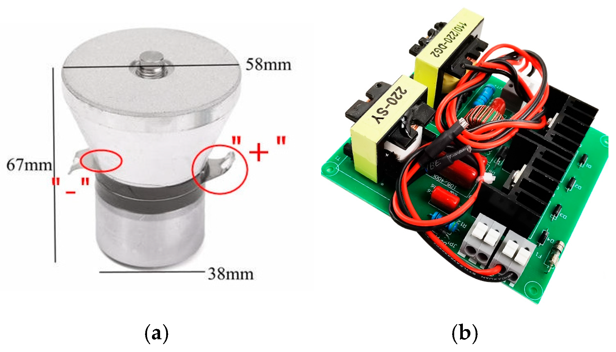
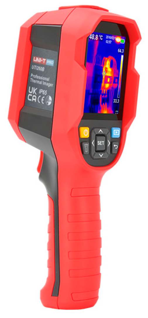
An experimental setup was developed to carry out the ultrasonic treatment (Figure 1). The setup consists of a transparent container (1), an ultrasonic emitter (2), a generator (3), and an ultrasonic wave reflector (4). Transparent polypropylene containers with high chemical resistance and glass containers were used as the housing. The ultrasonic wave emitter (Figure 2) was mounted at the top of the housing and connected to the ultrasonic vibration generator (Figure 2a). The heating process of the metalworking fluid was monitored using a thermal imager (model UTi260B) (Figure 3 and Figure 4c).
The experiments were carried out using an ultrasonic generator (model Granbo DG2-J100 DIY Accessories for Ultrasonic Cleaner, China) with a nominal power of 100 W, operating at an ultrasonic frequency of 40 kHz and a drive board transducer kit rated at 100 W. The ultrasonic transducer probe (model JP-100T) was selected with a working frequency range of 25–40 kHz and available power variants of 50 W, 60 W, 100 W and 120 W; this model exhibits high electro-acoustic conversion efficiency and output amplitude suitable for industrial cleaning applications. The emitter was mounted at the top-centre of the container, with a vertical insertion depth of approximately 15–20 mm from the vessel bottom, to ensure a uniform acoustic field throughout the volume.
The cutting fluid used in this study was a commercially available soluble metalworking fluid UNISOL EP 2. According to the manufacturer’s technical data sheet, UNISOL EP 2 is a mineral-oil-based water-miscible emulsion containing a balanced system of anionic/non-ionic emulsifiers, corrosion inhibitors, antifoam and biocidal additives. The concentrate is amber in color, with a density of 0.95 kg/L and a pH of 9.4 for a 3% aqueous solution.
The working emulsion was prepared by diluting the concentrate in tap water to a 5% volume concentration (approximately 1:20 oil–water ratio), which falls within the manufacturer’s recommended range of 4–6% for general machining operations. The fluid is designed for ferrous and non-ferrous metals and is suitable for water hardness between 50 and 350 ppm Ca.
Cutting fluid samples were collected directly from an operating metalworking facility, where the same type of emulsion was used in multiple machine tools. Three characteristic contamination levels were distinguished based on a combination of physicochemical indicators and visual inspection:
Clean cutting fluid (Sample A): freshly prepared emulsion from the central supply system, transparent, light-colored, with parameters corresponding to the initial state of the fluid.
Moderately contaminated cutting fluid (Sample B): fluid taken after 2–3 weeks of use, showing a slightly darker color and minor suspended metallic particles; optical and density parameters showing moderate deviation from the clean sample.
Highly contaminated cutting fluid (Sample C): fluid after more than one month of operation, dark in color with visible metallic sediment and oil film; parameters indicating the highest degree of contamination. All measured values of refractive index and density for the studied samples are presented in Table 3.
The classification was thus based on a combination of operational age, optical and density measurements, and visual characteristics of the samples. These values were verified before ultrasonic treatment and used to quantify the cleaning efficiency.
The experimental methodology involves determining the dependence of density—which characterizes the degree of contamination of the cutting fluid—on time, as well as the dependence of the refractive index of the cutting fluid on time. These parameters were measured at different stages of the process. The experiments were conducted in three stages:
Stage 1 (preparatory): performed without activating the ultrasonic generator;
Stage 2: performed with the ultrasonic generator activated;
Stage 3: performed without activating the ultrasonic generator (a holding period after treatment).
During the preparatory stage, the refractive index, mass, and temperature of the fluid were measured. The cutting fluid was then subjected to ultrasonic treatment for 5 min. Measurements were taken immediately after the treatment was completed, following a 5 min resting period, and repeated again after a 24 h resting period.
Statistical analysis of the obtained data was carried out using a one-way analysis of variance to determine the influence of ultrasonic frequency and container material on cleaning efficiency. The analysis confirmed statistically significant effects (p < 0.05) for both factors.
The selection of container volumes (1 L, 3 L, and 5 L) was based on the need to evaluate the influence of the treated fluid volume on the efficiency of ultrasonic cleaning while maintaining a comparable energy density and uniform acoustic field distribution. These volumes correspond to typical laboratory and pilot-scale vessels used for studying ultrasonic processes, ensuring reproducible cavitation conditions across experiments. In addition, this range reflects the practical reservoir capacities commonly employed in small- and medium-sized machining systems, thereby allowing the obtained results to be extrapolated to real industrial applications.
The ultrasonic power of 100 W was selected according to the specifications of the generator and the parameters that, according to previous studies, provide stable cavitation and effective disruption of emulsified contaminants in aqueous systems [53,54,60,61,62]. The ultrasonic exposure time was limited to 5 min, as longer treatment led to noticeable heating of the fluid and the onset of boiling, which could distort the cavitation process and affect measurement accuracy.

3. Results

During the experiment, ultrasonic treatment directly affected both the container walls and the cutting fluid itself.
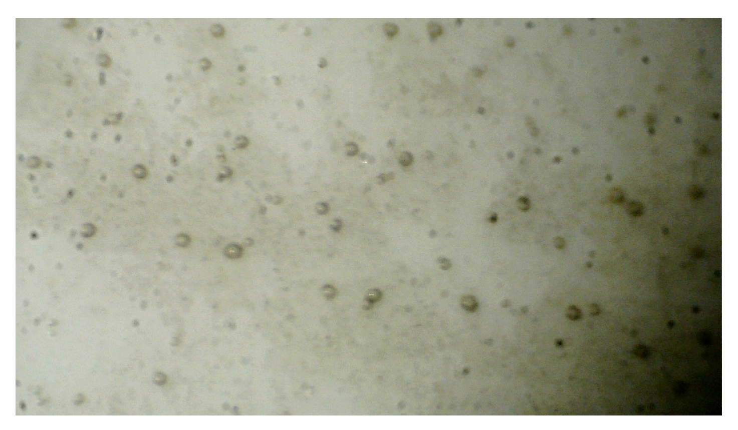
When the cutting fluid was directly exposed to ultrasonic vibrations, small black concretions formed, consisting of metal particles, dust, and other debris (Figure 5).
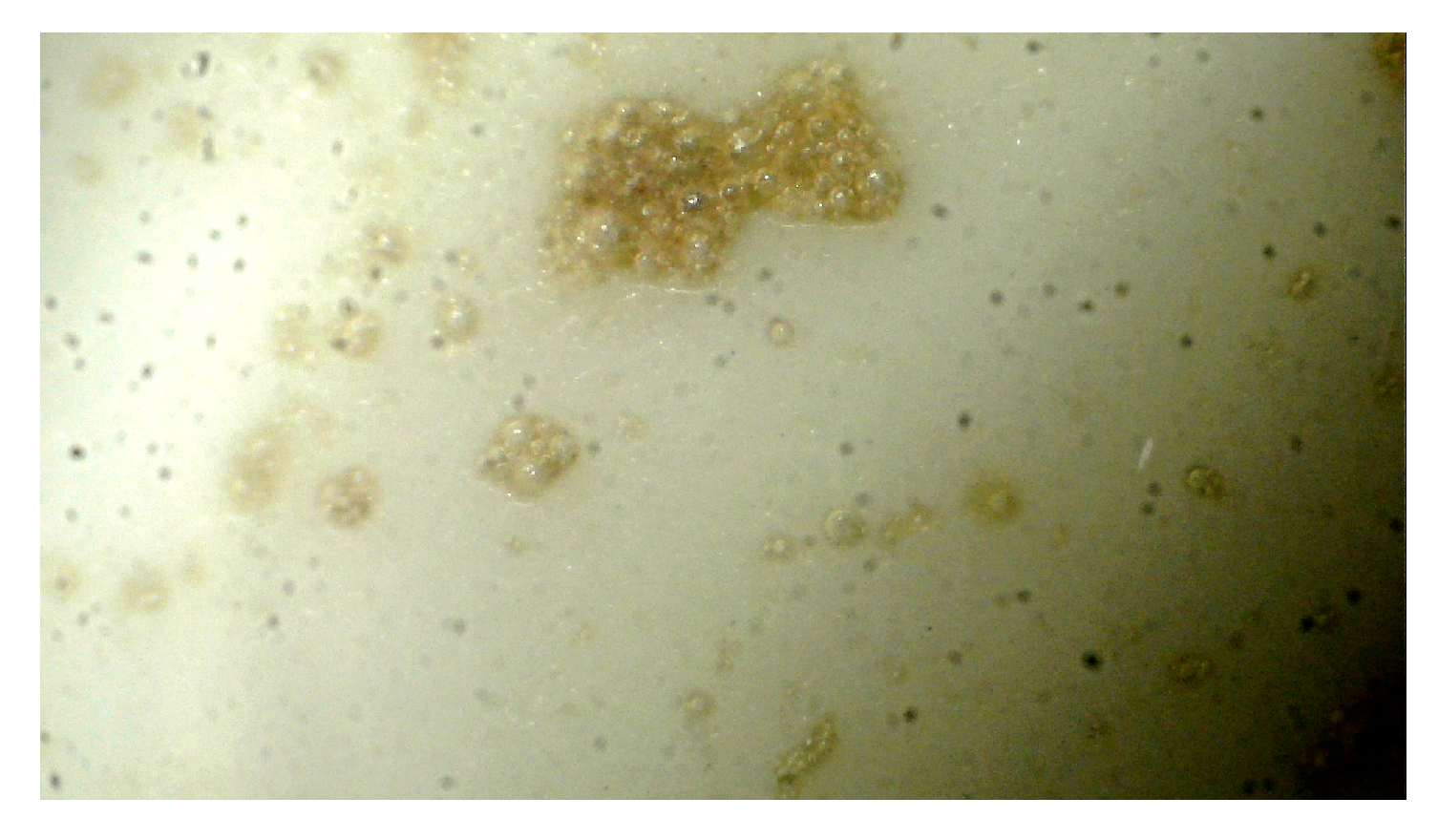
When ultrasonic waves interacted with the container walls, air bubbles were generated near the surface, capturing a greater amount of metal and debris compared with the previous test (Figure 6). These bubbles ascended toward the center of the container, forming a distinct pattern, and over time, a contaminated layer accumulated at the top of the fluid (Figure 4b).
The degree of cleaning was determined by the parameter ρ c . The obtained results made it possible to propose a hypothesis concerning the physical nature of the process under study. Formally, this process is described by Equation (3). When energy is transferred to the cutting fluid, the value of the first term in Equation (3), d V d h μ , increases.
This occurs because the dynamic viscosity (μ) rises, transitioning into what is known as the apparent viscosity—having a higher magnitude but a slightly different physical interpretation [67]. The derivative d V d h also increases as a result of the growing fluid velocity (V) and the decreasing thickness of its layers (h). The second term in Equation (3) increases even more significantly due to the quadratic dependence on d V d h .
As a result, the frictional forces within the cutting fluid increase sharply, as represented by the shear stress value τ . This leads to a rapid breakdown of intermolecular bonds within the fluid, particularly at the fluid–metal interface. Consequently, the protective layer surrounding the metal particles is disrupted (Figure 7).
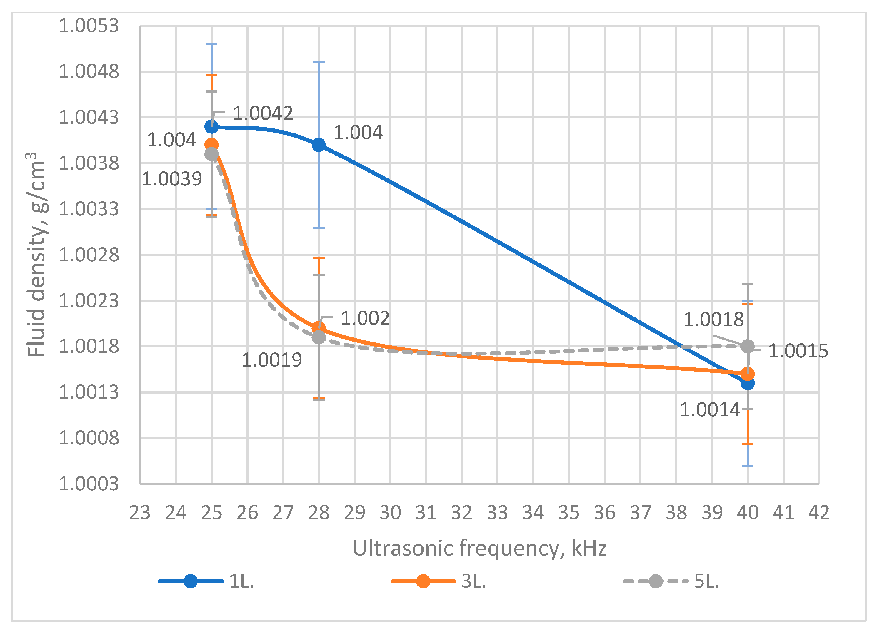
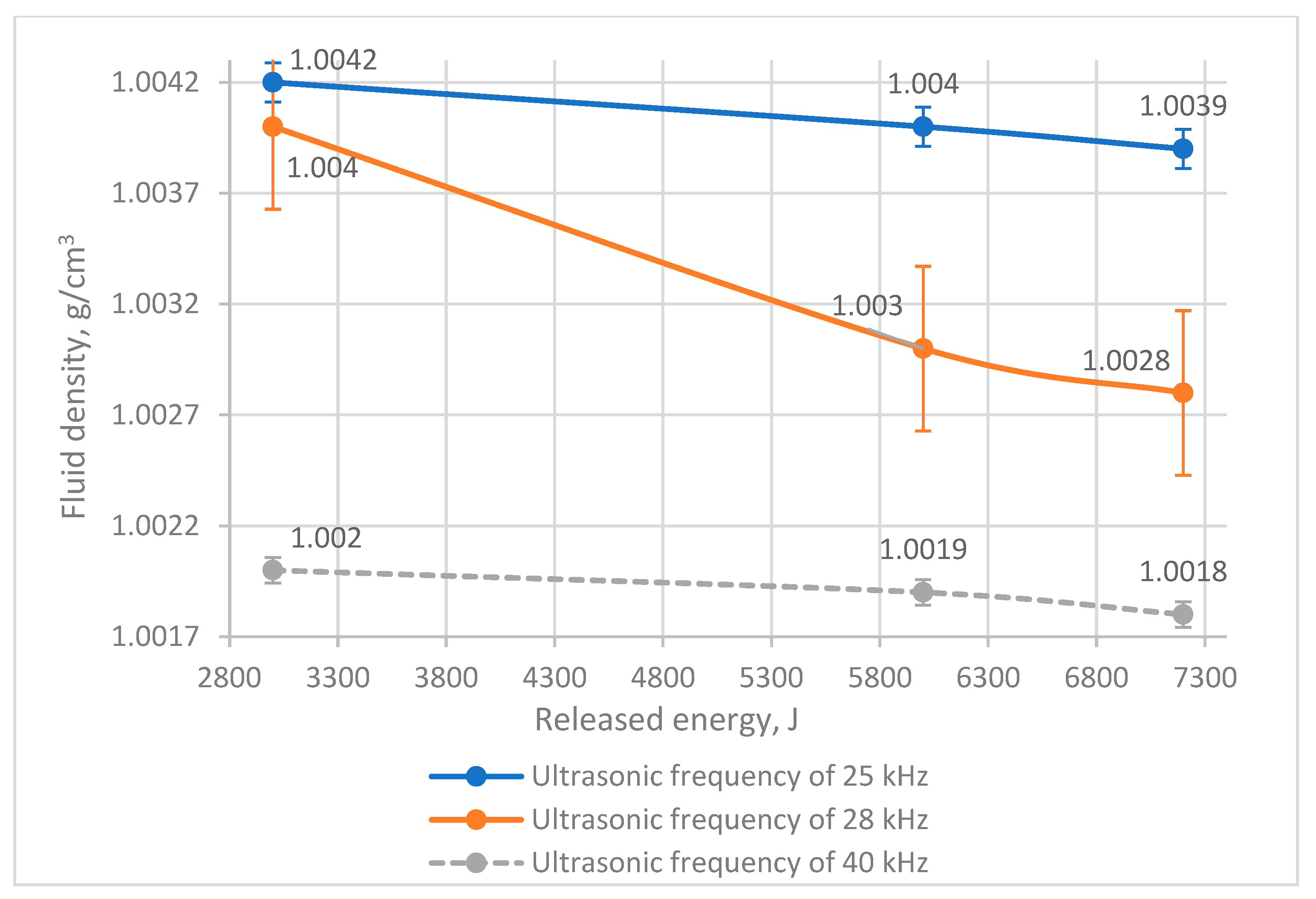
Air released as a result of cavitation occupies the protective layer because a low-pressure zone is formed in that region. The resulting bubble has a lower density than the cutting fluid, causing it to rise toward the surface. The graphs illustrating this process are presented in Figure 8, Figure 9 and Figure 10. Each experimental condition was repeated three times (n = 3). Results are presented as mean ± standard deviation (SD). Error bars in Figure 8, Figure 9 and Figure 10 illustrate the data fluctuation range and ensure consistency with statistical representation.
During the experiment, samples of the cutting fluid were collected at various stages to assess the degree of cleaning. All samples were obtained by extracting equal volumes of fluid from the upper and lower sections of the container subjected to ultrasonic treatment.
The primary method used to determine the degree of contamination and cleaning of the cutting fluid was refractometry, performed with a refractometer. Refractometry is a technique for studying substances based on the measurement of the refractive index (coefficient) and its related functions. It is employed to identify chemical compounds, perform quantitative and structural analyses, and determine the physicochemical parameters of substances. The instrument measures the optical properties of fluids using light refraction and provides readings on a scale in degrees Brix (°Bx), which indicates the concentration of dissolved solids in the fluid.
The refractometer determines the deviation angle of a light beam from its straight path as it passes from one medium to another. The relationship between the angle of incidence and the angle of refraction at the interface between two media defines the refractive index.
This indicator increases proportionally with the density of the substance. The relative “weight” of the sample is determined by the refractometer in comparison with distilled water, which serves as the calibration standard for the instrument.
As a result of the study, all necessary calculations were carried out. Based on the obtained data, the density of the fluid before and after cleaning was calculated. The density of the cutting fluid prior to treatment was found to be higher than that after treatment. The apparent density of the cutting fluid was indirectly estimated from the measured °Brix values obtained with a refractometer. The conversion between refractive index (°Brix) and fluid density was performed according to standard Brix-specific gravity tables (at 20 °C), which are commonly used for industrial emulsions and aqueous solutions. This approach enables estimation of the cutting fluid’s concentration and contamination level without direct measurement of its mass or volume. All results are summarized in Table 3.
Based on the obtained data and the calculations performed, it was determined that the density of the fluid before treatment was higher than that after treatment, thereby confirming that ultrasonic treatment of the cutting fluid promotes the cleaning process.
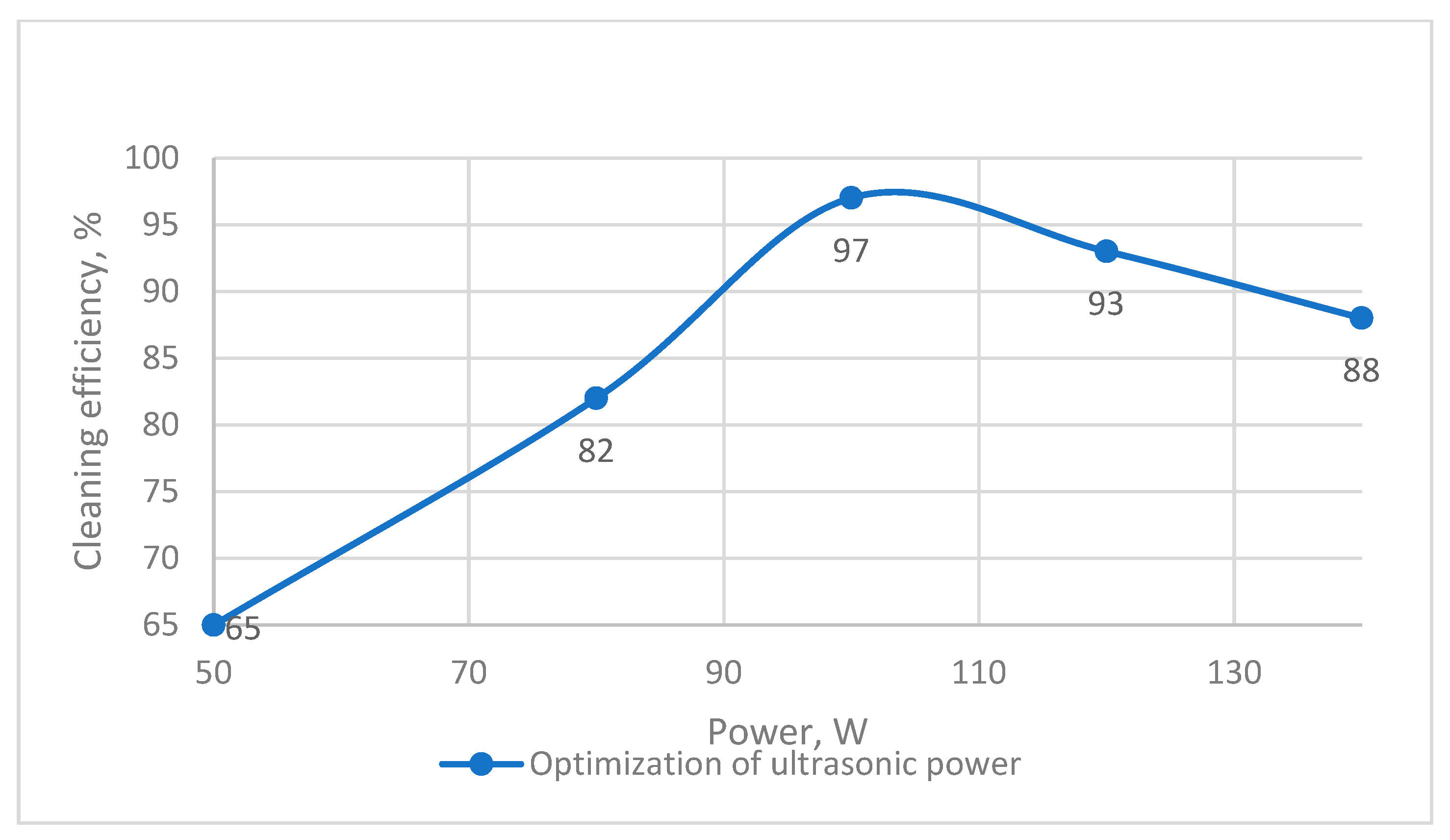
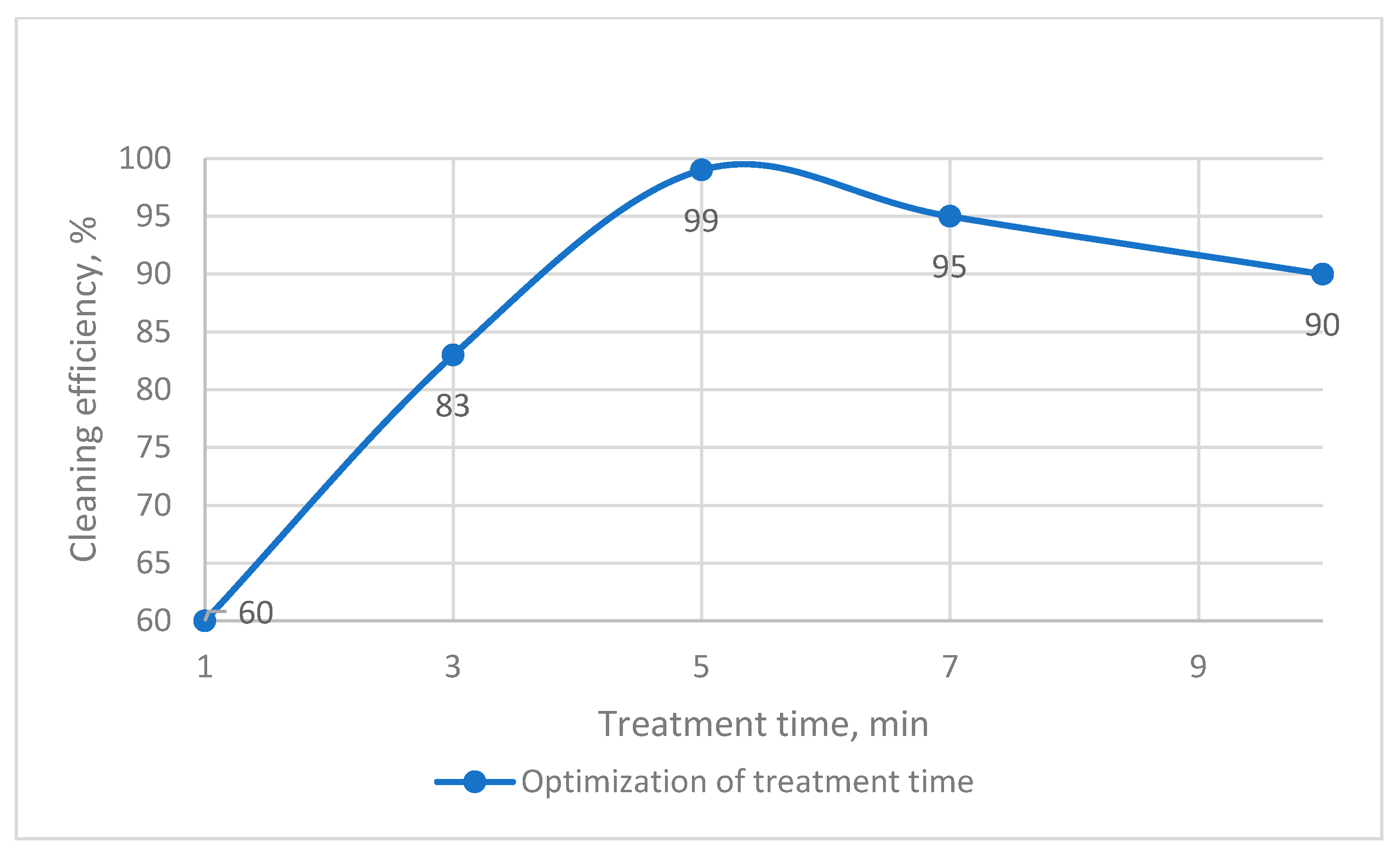
To identify the optimal operating parameters of ultrasonic treatment, additional analytical curves were constructed (Figure 11, Figure 12 and Figure 13). These graphs illustrate the effect of ultrasonic frequency, power, and treatment time on the cleaning efficiency of cutting fluids.
As shown in Figure 11, the efficiency increased with frequency, reaching a maximum at 28 kHz, beyond which excessive cavitation turbulence caused a slight decline in performance. Figure 12 demonstrates that cleaning efficiency grew proportionally with power up to 100 W, after which further increase did not result in significant improvement, mainly due to overheating and nonuniform cavitation. Figure 13 shows that the cleaning effect intensified with treatment duration up to 5 min, while longer exposure produced only marginal gains.
Based on these results, the combination of 28 kHz frequency, 100 W power, and 5 min treatment time was selected as the optimal operating mode, providing the highest cleaning efficiency (96–98%) with minimal energy consumption.

4. Conclusions

Thus, the hypothesis that ultrasonic waves can effectively clean cutting fluids was experimentally validated. Throughout the experiment, several physical processes were observed that directly influenced the cleaning mechanism, namely the following:
-
Heating;
-
Cavitation;
-
Coagulation;
-
Dispersion.
By analyzing the experimental data, the density of the fluid before and after ultrasonic treatment was calculated. The results showed that after treatment, the density decreased by approximately 0.002–0.004 g/cm3 compared to the initial state, and the refractive index (°Bx) correspondingly declined, indicating a reduction in solid and oil contaminants. The most pronounced cleaning efficiency was achieved at 28 kHz with a treatment duration of 5 min. Under these conditions, the cleaning efficiency reached up to 96–98%, depending on the initial contamination level.
This cleaning method is simple to implement and highly effective for cutting fluids with various contamination levels and compositions. Moreover, ultrasonic treatment at moderate power (100 W) ensures efficient regeneration of cutting fluids without chemical reagents or complex filtration systems. This approach significantly reduces the consumption of fresh fluid and the volume of hazardous waste, thereby lowering operational costs and environmental impact. The developed ultrasonic cleaning method is therefore environmentally friendly and can be directly applied in industrial workshops for the periodic regeneration of cutting fluids in closed-loop systems.
Scaling analysis between laboratory and industrial conditions demonstrated that the optimized parameters (28 kHz, 100 W, 5 min) can be proportionally adjusted for larger treatment volumes by maintaining constant acoustic energy density (W/cm3) and ensuring uniform cavitation field distribution through multiple transducers or reflector geometry optimization. When scaled to pilot-level systems (volumes of 20–50 L), equivalent cleaning efficiency can be achieved at power inputs of 0.8–1.2 kW with exposure times of 5–8 min. These correlations confirm the applicability of the developed ultrasonic cleaning technology for industrial recirculation loops of metalworking fluids.

5. Patents

The outcome of this study was the granting of Patent No. 10845 (Republic of Kazakhstan, utility model, 11 July 2025) for the invention entitled “Method of Cleaning the Cooling Lubricating Fluid”.

Author Contributions

Conceptualization, A.K. (Anna Kim); methodology, A.K. (Adil Kadyrov); formal analysis, A.K. (Adil Kadyrov), K.S. (Karibek Sherov), V.Y.; investigation, A.K. (Adil Kadyrov); resources, K.S. (Kirill Sinelnikov), A.K. (Anna Kim); writing—original draft preparation and data curation, A.K. (Anna Kim), A.K. (Adil Kadyrov); writing—review and editing, A.K. (Adil Kadyrov), K.S. (Karibek Sherov), V.Y. All authors have read and agreed to the published version of the manuscript.

Funding

This research was funded by the Science Committee of the Ministry of Education and Science of the Republic of Kazakhstan, Grant No. AP 25794035.

Institutional Review Board Statement

Not applicable.

Informed Consent Statement

Not applicable.

Data Availability Statement

The original contributions presented in this study are included in the article. Further inquiries can be directed to the corresponding author.

Acknowledgments

The authors gratefully acknowledge the financial support provided by the Science Committee of the Ministry of Education and Science of the Republic of Kazakhstan under Grant No. AP 25794035.

Conflicts of Interest

The authors declare no conflicts of interest. The funders had no role in the design of the study; in the collection, analyses, or interpretation of data; in the writing of the manuscript; or in the decision to publish the results.

References

  1. Brinksmeier, E.; Meyer, D.; Huesmann-Cordes, A.G.; Herrmann, C. Metalworking fluids—Mechanisms and performance. CIRP Ann. 2015, 64, 605–628. [Google Scholar] [CrossRef]
  2. Singh, J.; Gill, S.S.; Dogra, M.; Singh, R. A review on cutting fluids used in machining processes. Eng. Res. Express 2021, 3, 012002. [Google Scholar] [CrossRef]
  3. Kui, G.W.A.; Islam, S.; Reddy, M.M.; Khandoker, N.; Chen, V.L.C. Recent progress and evolution of coolant usages in conventional machining methods: A comprehensive review. Int. J. Adv. Manuf. Technol. 2022, 119, 3–40. [Google Scholar] [CrossRef]
  4. Mayr, J.; Gebhardt, M.; Massow, B.B.; Weikert, S.; Wegener, K. Cutting Fluid Influence on Thermal Behavior of 5-axis Machine Tools. Procedia CIRP 2014, 14, 395–400. [Google Scholar] [CrossRef]
  5. Yan, P.; Rong, Y.; Wang, G. The effect of cutting fluids applied in metal cutting process. Eng. Manuf. 2016, 230, 19–37. [Google Scholar] [CrossRef]
  6. Fang, Z.; Obikawa, T. Influence of cutting fluid flow on tool wear in high-pressure coolant turning using a novel internally cooled insert. J. Manuf. Process. 2020, 56 Pt A, 1114–1125. [Google Scholar] [CrossRef]
  7. Xavior, M.A.; Adithan, M. Determining the influence of cutting fluids on tool wear and surface roughness during turning of AISI 304 austenitic stainless steel. J. Mater. Process. Technol. 2009, 209, 900–909. [Google Scholar] [CrossRef]
  8. Diniz, A.E.; Micaroni, R. Influence of the direction and flow rate of the cutting fluid on tool life in turning process of AISI 1045 steel. Int. J. Mach. Tools Manuf. 2007, 47, 247–254. [Google Scholar] [CrossRef]
  9. Liew, P.J.; Shaaroni, A.; Sidik, N.A.C.; Yan, J. An overview of current status of cutting fluids and cooling techniques of turning hard steel. Int. J. Heat Mass Transf. 2017, 114, 380–394. [Google Scholar] [CrossRef]
  10. Moura, R.R.; da Silva, M.B.; Machado, Á.R.; Sales, W.F. The effect of application of cutting fluid with solid lubricant in suspension during cutting of Ti-6Al-4V alloy. Wear 2015, 332–333, 762–771. [Google Scholar] [CrossRef]
  11. Tanaka, R.; Hosokawa, A.; Furumoto, T.; Okada, M.; Ueda, T. Influence of cutting fluid on tool edge temperature in end milling titanium alloy. J. Adv. Mech. Des. Syst. Manuf. 2015, 9, JAMDSM0074. [Google Scholar] [CrossRef]
  12. Irani, R.; Bauer, R.; Warkentin, A. A review of cutting fluid application in the grinding process. Int. J. Mach. Tools Manuf. 2005, 45, 1696–1705. [Google Scholar] [CrossRef]
  13. El Baradie, M.A. Cutting fluids: Part I. Characterisation. J. Mater. Process. Technol. 2009, 56, 786–797. [Google Scholar] [CrossRef]
  14. Araoyinbo, A.O.; Edun, M.B.; Samuel, A.U.; Rahmat, A.; Biodun, M.B.; Albakri, M.M. Influence of cutting fluid on machining processes: A review. J. Kejuruter. 2022, 34, 365–373. [Google Scholar] [CrossRef]
  15. Çakīr, O.; Yardimeden, A.; Ozben, T.; Kilickap, E. Selection of cutting fluids in machining processes. J. Achiev. Mater. Manuf. Eng. 2007, 25, 99–102. [Google Scholar]
  16. Boruah, P.K.; Ramu, P.; Babu, G.K.; Arunachalam, R. Green Metalworking Fluids for Sustainable Machining Operations: A Review. Metals 2022, 12, 1466. [Google Scholar] [CrossRef]
  17. Debnath, S.; Reddy, M.M.; Yi, Q.S. Environmental friendly cutting fluids and cooling techniques in machining: A review. J. Clean. Prod. 2014, 83, 33–47. [Google Scholar] [CrossRef]
  18. Afonso, I.S.; Nobrega, G.; Lima, R.; Gomes, J.R.; Ribeiro, J.E. Conventional and Recent Advances of Vegetable Oils as Metalworking Fluids (MWFs): A Review. Lubricants 2023, 11, 160. [Google Scholar] [CrossRef]
  19. Tang, L.; Zhang, Y.; Li, C.; Zhou, Z.; Nie, X.; Chen, Y.; Cao, H.; Liu, B.; Zhang, N.; Said, Z.; et al. Biological Stability of Water-Based Cutting Fluids: Progress and Application. Chin. J. Mech. Eng. 2021, 35, 3. [Google Scholar] [CrossRef]
  20. Srinivas, M.S.; Kumar, D.; Suvin, P.S.; Kailas, S.V.; Pawar, S.; Choudhury, M.R. Green Lubricants in Action: Performance of Groundnut Oil-Based Cutting Fluids. Phys. Scr. 2023, 98, 075085. [Google Scholar] [CrossRef]
  21. Jeevan, T.; Jayaram, S. Tribological Properties and Machining Performance of Vegetable Oil Based Metal Working Fluids—A Review. Mod. Mech. Eng. 2018, 8, 42–65. [Google Scholar] [CrossRef]
  22. Ozcelik, B.; Kuram, E.; Demirbas, E.; Sik, E. Effects of vegetable-based cutting fluids on the wear in drilling. Sādhanā 2013, 38, 687–706. [Google Scholar] [CrossRef]
  23. Rapeti, P.; Krishna, V. Performance evaluation of vegetable oil-based nano cutting fluids in machining using Grey Relational Analysis—A step towards sustainable manufacturing. J. Clean. Prod. 2018, 172, 2862–2876. [Google Scholar] [CrossRef]
  24. Kim, A.; Petronienė, J.J.; Dzedzickis, A.; Bučinskas, V. Development of methodology for monitoring of metalworking fluids quality. J. Meas. Eng. 2025, 13, 1–14. [Google Scholar] [CrossRef]
  25. Gordon, T. Metalworking Fluid—The Toxicity of a Complex Mixture. J. Toxicol. Environ. Health Part A 2004, 67, 209–219. [Google Scholar] [CrossRef]
  26. Cheng, C.; Phipps, D.; Alkhaddar, R.M. Treatment of spent metalworking fluids. Water Res. 2005, 39, 4051–4063. [Google Scholar] [CrossRef] [PubMed]
  27. Clarens, A.F.; Zimmerman, J.B.; Keoleian, G.A.; Hayes, K.F.; Skerlos, S.J. Comparison of life cycle emissions and energy consumption for environmentally adapted metalworking fluid systems. Environ. Sci. Technol. 2008, 42, 8534–8540. [Google Scholar] [CrossRef]
  28. Zelenko, Y.; Bezovska, M.; Kuznetsov, V.; Muntian, A. Technological and ecological aspects of disposal of spent cutting fluids. J. Ecol. Eng. 2021, 22, 207–212. [Google Scholar] [CrossRef]
  29. Zhang, Y.; Wu, L.; Zhang, X.; Ge, B.; Qi, Y. Demulsification treatment of spent metalworking fluids by metal cations: The synergistic effect and efficiency evaluation. Processes 2021, 9, 1807. [Google Scholar] [CrossRef]
  30. Di Martino, P. Ways to improve biocides for metalworking fluid. AIMS Microbiol. 2021, 7, 13–27. [Google Scholar] [CrossRef] [PubMed]
  31. Feng, W.; Yin, Y.; de Lourdes Mendoza, M.; Wang, L.; Chen, X.; Liu, Y.; Cai, L.; Zhang, L. Freeze-thaw method for oil recovery from waste cutting fluid without chemical additions. J. Clean. Prod. 2017, 148, 84–89. [Google Scholar] [CrossRef]
  32. Trafny, E.A.; Lewandowski, R.; Kozłowska, K.; Zawistowska-Marciniak, I.; Stepińska, M. Microbial contamination and biofilms on machines of metal industry using metalworking fluids with or without biocides. Int. Biodeterior. Biodegrad. 2015, 99, 31–38. [Google Scholar] [CrossRef]
  33. Passman, F.J.; Küenzi, P. A differential adenosine triphosphate test method for differentiating between bacterial and fungal contamination in water-miscible metalworking fluids. Int. Biodeterior. Biodegrad. 2015, 99, 125–137. [Google Scholar] [CrossRef]
  34. Di Maiuta, N.; Rüfenacht, A.; Küenzi, P. Assessment of bacteria and archaea in metalworking fluids using massive parallel 16S rRNA gene tag sequencing. Lett. Appl. Microbiol. 2017, 65, 266–273. [Google Scholar] [CrossRef] [PubMed]
  35. Elansky, S.N.; Chudinova, E.M.; Elansky, A.S.; Kah, M.O.; Sandzhieva, D.A.; Mukabenova, B.A.; Dedov, A.G. Microorganisms in spent water-miscible metalworking fluids as a resource of strains for their disposal. J. Clean. Prod. 2022, 350, 131438. [Google Scholar] [CrossRef]
  36. Ruiz, C.; von Känel, G.; Burkard, S.; Küenzi, P. Fusarium spp. Metalworking Fluid Systems: Companions Forever. Pathogens 2024, 13, 990. [Google Scholar] [CrossRef]
  37. Marchand, G.; Lavoie, J.; Racine, L.; Lacombe, N.; Cloutier, Y.; Bélanger, É.; Lemelin, C.; Desroches, J. Evaluation of Bacterial Contamination and Control Methods in Soluble Metalworking Fluids. J. Occup. Environ. Hyg. 2010, 7, 358–366. [Google Scholar] [CrossRef]
  38. Rosenman, K. Occupational diseases in individuals exposed to metal working fluids. Curr. Opin. Allergy Clin. Immunol. 2015, 15, 131–136. [Google Scholar] [CrossRef]
  39. Thornéus, E.; Graff, P.; Bryngelsson, I.-L.; Nordenberg, E.; Ghafouri, B.; Johansson, H.; Fornander, L. Occupational Exposure to Metalworking Fluid and the Effect on Health Symptoms—An Intervention Study. J. Occup. Environ. Med. 2021, 63, e667–e672. [Google Scholar] [CrossRef]
  40. Friesen, M.C.; Costello, S.; Eisen, E.A. Quantitative exposure to metalworking fluids and bladder cancer incidence in a cohort of autoworkers. Am. J. Epidemiol. 2009, 169, 1471–1478. [Google Scholar] [CrossRef]
  41. Costello, S.; Friesen, M.C.; Christiani, D.C.; Eisen, E.A. Metalworking fluids and malignant melanoma in autoworkers. Epidemiology 2010, 22, 90–97. [Google Scholar] [CrossRef]
  42. CDC/NIOSH. Investigation of Dermal and Respiratory Exposures to Metalworking Fluid Mists: Implications for Skin and Lung Health. In Health Hazard Evaluation Report; Report No. HETA 2013 0075 3264; National Institute for Occupational Safety and Health: Morgantown, WV, USA, 2014. Available online: https://www.cdc.gov/niosh/hhe/reports/pdfs/2013-0075-3264.pdf (accessed on 25 August 2025).
  43. Lillienberg, L.; Andersson, E.M.; Järvholm, B.; Torén, K. Respiratory symptoms and exposure–response relations in workers exposed to metalworking fluid aerosols. Ann. Occup. Hyg. 2010, 54, 403–411. [Google Scholar] [CrossRef]
  44. Park, R.M. Risk assessment for metalworking fluids and cancer outcomes. Am. J. Ind. Med. 2018, 61, 198–203. [Google Scholar] [CrossRef]
  45. Lin, C.-C.; Wu, J.-M. A Novel Centrifugal Filtration Device. Separations 2022, 9, 129. [Google Scholar] [CrossRef]
  46. Wu, X.; Li, C.; Zhou, Z.; Nie, X.; Chen, Y.; Zhang, Y.; Cao, H.; Liu, B.; Zhang, N.; Said, Z.; et al. Circulating purification of cutting fluid: An overview. Int. J. Adv. Manuf. Technol. 2021, 117, 2565–2600. [Google Scholar] [CrossRef]
  47. Popović, S.; Karadžić, M.; Cakl, J. Optimization of ultrafiltration of cutting oil wastewater enhanced by application of twisted tapes: Response surface methodology approach. J. Clean. Prod. 2019, 231, 320–330. [Google Scholar] [CrossRef]
  48. Chen, P.; Yin, D.; Song, P.; Liu, Y.; Cai, L.; Wang, H.; Zhang, L. Demulsification and oil recovery from oil-in-water cutting fluid wastewater using electrochemical micromembrane technology. J. Clean. Prod. 2020, 244, 118698. [Google Scholar] [CrossRef]
  49. Nam, C.T.H.; Hien, N.T.T.; Hiep, H.H.; Thuong, N.T. Treatment of Cutting Oil-in-Water Emulsion by Combining Flocculation and Fenton Oxidation and Membrane Filtration. J. Chem. 2021, 2021, 7248402. [Google Scholar] [CrossRef]
  50. Chang, Y.Y.; Yu, J.J.; Wang, S.P.; Ma, H.J. Effect of freezing-air thawing pretreatment of cutting fluid wastewater on the organics’ distribution, transfer and transformation. J. Water Process Eng. 2023, 52, 103514. [Google Scholar] [CrossRef]
  51. Feng, W.; Yin, Y.; de Lourdes Mendoza, M.; Wang, L.; Chen, P.; Liu, Y.; Cai, L.; Zhang, L. Oil recovery from waste cutting fluid via the combination of suspension crystallization and freeze-thaw processes. J. Clean. Prod. 2018, 172, 481–487. [Google Scholar] [CrossRef]
  52. Dermouchi, A.; Lendormi, T.; Arris, S.; Zerdazi, R.; Lanoiselle, J.-L.; Bencheikh-Lehocine, M. The feasibility of combining an electrocoagulation process and a biological treatment for the degradation of cutting oil emulsions. Desalination Water Treat. 2021, 220, 265–276. [Google Scholar] [CrossRef]
  53. Garcia-Costa, A.L.; Luengo, A.; Zazo, J.A.; Casas, J.A. Cutting oil-water emulsion wastewater treatment by microwave assisted catalytic wet peroxide oxidation. Sep. Purif. Technol. 2021, 257, 117940. [Google Scholar] [CrossRef]
  54. Jalal, J.; Leong, T. Microstreaming and Its Role in Applications: A Mini-Review. Fluids 2018, 3, 93. [Google Scholar] [CrossRef]
  55. Antes, F.G.; Diehl, L.O.; Pereira, J.S.F.; Guimarães, R.C.L.; Guarnieri, R.A.; Ferreira, B.M.S.; Dressler, V.L.; Flores, E.M.M. Feasibility of low frequency ultrasound for water removal from crude oil emulsions. Ultrason. Sonochem. 2015, 25, 70–75. [Google Scholar] [CrossRef]
  56. Sadatshojaie, A.; Wood, D.A.; Jokar, S.M.; Rahimpour, M.R. Applying ultrasonic fields to separate water contained in medium-gravity crude oil emulsions and determining crude oil adhesion coefficients. Ultrason. Sonochem. 2021, 70, 105303. [Google Scholar] [CrossRef]
  57. Zakani, B.; Grecov, D. Effect of ultrasonic treatment on yield stress of highly concentrated cellulose nano-crystalline (CNC) aqueous suspensions. Carbohydr. Polym. 2022, 291, 119651. [Google Scholar] [CrossRef]
  58. Salehi, F.; Inanloodoghouz, M.; Karami, M. Rheological properties of carboxymethyl cellulose (CMC) solution: Impact of high-intensity ultrasound. Ultrason. Sonochem. 2023, 101, 106655. [Google Scholar] [CrossRef] [PubMed]
  59. Zhu, L.; Lyu, W.; Yang, P.; Wang, Z. Effect of ultrasound on the flocculation-sedimentation and thickening of unclassified tailings. Ultrason. Sonochem. 2020, 66, 104984. [Google Scholar] [CrossRef] [PubMed]
  60. Settnes, M.; Bruus, H. Forces acting on a small particle in an acoustical field in a viscous fluid. Phys. Rev. E 2012, 85, 016327. [Google Scholar] [CrossRef] [PubMed]
  61. Lauteri, C.; Ferri, G.; Piccinini, A.; Pennisi, L.; Vergara, A. Ultrasound Technology as Inactivation Method for Foodborne Pathogens: A Review. Foods 2023, 12, 1212. [Google Scholar] [CrossRef] [PubMed]
  62. Yu, L.; Han, M.; He, F. A review of treating oily wastewater. Arab. J. Chem. 2017, 10 (Suppl. 2), S1913–S1922. [Google Scholar] [CrossRef]
  63. Cambiella, A.; Benito, J.M.; Pazos, C.; Coca, J. Centrifugal Separation Efficiency in the Treatment of Waste Emulsified Oils. Chem. Eng. Res. Des. 2006, 84, 69–76. [Google Scholar] [CrossRef]
  64. Fukami, K.; Ogata, N.; Yamamoto, K.; Kawamura, K.; Mitani, I.; Sakamoto, M. Treatment and Effective Removal of Metal Fine Particles from Waste Cutting Fluids by Flotation via Microbubbles and Skimming. Water 2022, 14, 2575. [Google Scholar] [CrossRef]
  65. Ibatov, M.K.; Kadyrov, A.S.; Pak, I.A.; Kadyrova, I.A.; Askarov, B.S. The results of experimental studies of the capacitive equipment of ultrasonic cleaning of exhaust gases of vehicles. Ugol/Coal 2020, 2, 73–78. [Google Scholar] [CrossRef]
  66. Kadyrov, A.; Bembenek, M.; Sarsembekov, B.; Kukesheva, A.; Nurkusheva, S. The Influence of the Frequency of Ultrasound on the Exhaust Gas Purification Process in a Diesel Car Muffler. Appl. Sci. 2024, 14, 5027. [Google Scholar] [CrossRef]
  67. Kadyrov, A.; Zhunusbekova, Z.; Ganyukov, A.; Kadyrova, I.; Kukesheva, A. General characteristics for loading the working elements of drilling and milling machines when moving in the clay solution. Commun. Sci. Lett. Univ. Zilina 2021, 23, B97–B105. [Google Scholar] [CrossRef]
  68. Bingham, E.C. An Investigation of the Laws of Plastic Flow. Bur. Stand. Bull. 1916, 13, 309. [Google Scholar] [CrossRef]
  69. Oldroyd, J.G. A Rational Formulation of the Equations of Plastic Flow for a Bingham Solid. Math. Proc. Camb. Philos. Soc. 1947, 43, 100–105. [Google Scholar] [CrossRef]
  70. Acheson, D.J. Elementary Fluid Dynamics; Oxford University Press: Oxford, UK, 1990. [Google Scholar]
  71. Georgiou, G.C. Fundamental Equations: Continuum Mechanics and Lattice Boltzmann Models; Springer: Berlin/Heidelberg, Germany, 2022. [Google Scholar] [CrossRef]
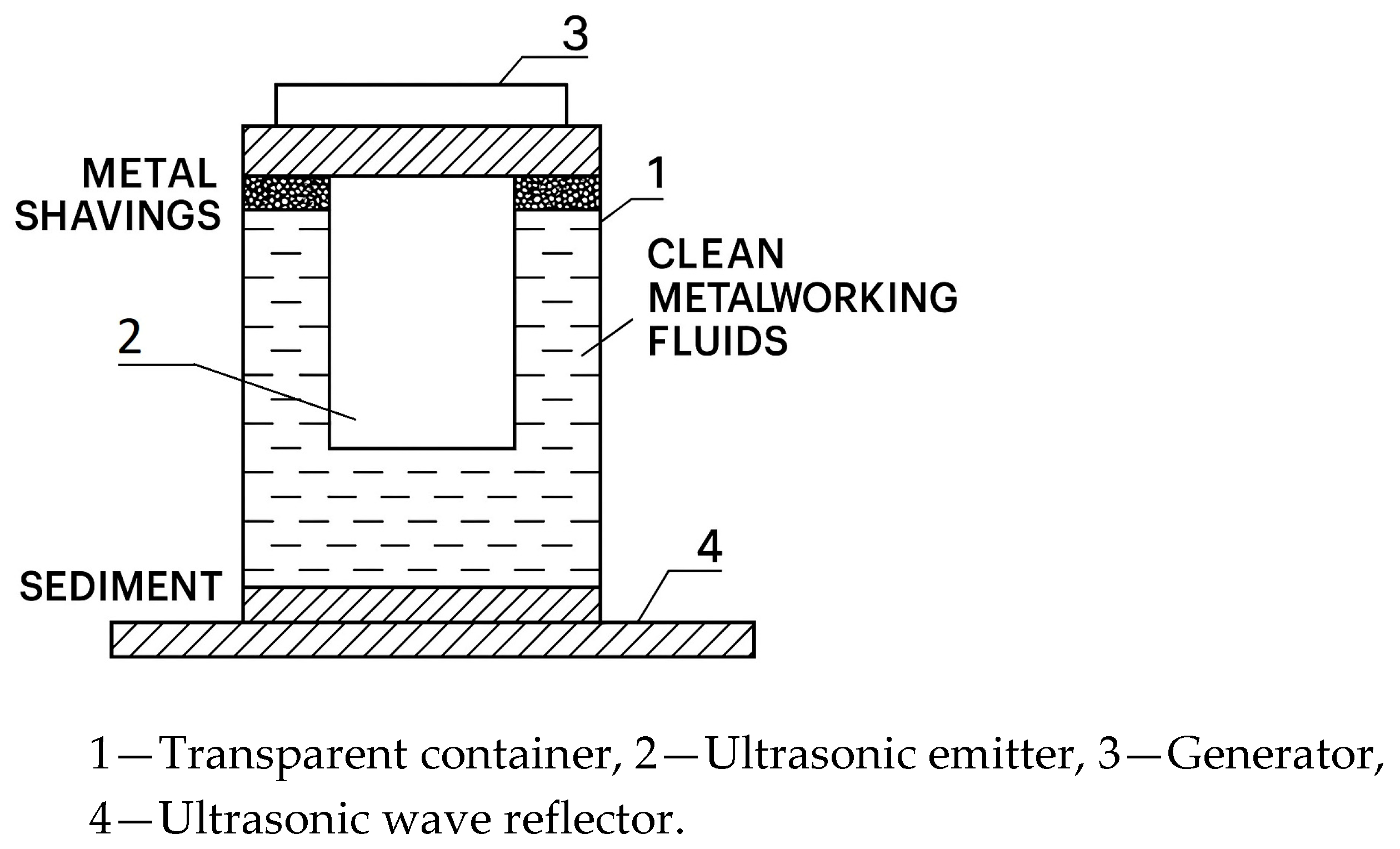
Figure 1. Diagram of the experimental setup for ultrasonic cleaning of cutting fluid.
Applmech 06 00083 g001
Figure 2. Ultrasonic wave emitter. (a) Ultrasonic generator. (b) Ultrasonic transducer.
Applmech 06 00083 g002
Figure 3. Thermal imager.
Applmech 06 00083 g003
Figure 4. Ultrasonic cleaning.
Applmech 06 00083 g004
Figure 5. Cavitation.
Applmech 06 00083 g005
Figure 6. Coagulation.
Applmech 06 00083 g006
Figure 7. The disruption of intermolecular bonds within the fluid at the fluid–metal interface.
Applmech 06 00083 g007
Figure 8. Changes in cutting fluid density depending on ultrasonic frequency and container volume. Error bars represent standard deviation (SD) for n = 3 replicate measurements. All data are expressed as mean ± SD.
Applmech 06 00083 g008
Figure 9. Changes in cutting fluid density depending on the frequency of the ultrasonic generator and the energy released per unit of time. Error bars represent standard deviation (SD) for n = 3 replicate measurements. All data are expressed as mean ± SD.
Applmech 06 00083 g009
Figure 10. Changes in cutting fluid density under ultrasonic treatment depending on volume. Error bars represent standard deviation (SD) for n = 3 replicate measurements. All data are expressed as mean ± SD.
Applmech 06 00083 g010
Figure 11. Optimization of ultrasonic frequency.
Applmech 06 00083 g011
Figure 12. Optimization of ultrasonic power.
Applmech 06 00083 g012
Figure 13. Optimization of treatment time.
Applmech 06 00083 g013
Table 1. Comparative characteristics of conventional and ultrasonic cleaning methods for metalworking fluids.
MethodTypical Efficiency, %Energy ConsumptionLimitations
Sedimentation60–70LowLong cycle time; ineffective for fine particles
Filtration (membrane)80–90MediumMembrane fouling; high replacement cost
Flotation75–85HighBubble coalescence; limited performance in viscous fluids
Centrifugation85–90Very highHigh energy demand; expensive equipment
Ultrasonic cleaning90–98Low–mediumEffective for submicron particles; enhances rheological stability
Table 2. The experiment plans.
Container VolumeContainer MaterialUltrasonic Generator Frequency
25 kHz28 kHz40 kHz
Clean Cutting FluidMedium ContaminationHigh ContaminationClean Cutting FluidMedium ContaminationHigh ContaminationClean Cutting FluidMedium ContaminationHigh Contamination
1000 mLPlastic container Measuring
Bx, %,
t, C
Glass
container
Measuring
Bx, %,
t, C
3000 mLPlastic container Measuring
Bx, %,
t, C
Glass
container
Measuring
Bx, %,
t, C
Measuring
Bx, %,
t, C
Measuring
Bx, %,
t, C
Measuring
Bx, %,
t, C
Measuring
Bx, %,
t, C
Measuring
Bx, %,
t, C
Measuring
Bx, %,
t, C
Measuring
Bx, %,
t, C
Measuring
Bx, %,
t, C
5000 mLPlastic container Measuring
Bx, %,
t, C
Glass
container
Measuring
Bx, %,
t, C
Table 3. Results of the experiment.
Container VolumeContainer MaterialUltrasonic Generator Frequency
25 kHz28 kHz40 kHz
Clean Cutting FluidMedium ContaminationHigh ContaminationClean Cutting FluidMedium ContaminationHigh ContaminationClean Cutting FluidMedium ContaminationHigh Contamination
1000 mLPlastic container Bx = 1.5%
t = 30 C
ρ = 1.0058 g/ c m 3
Glass container Bx = 1.1%
t = 35C
ρ = 1.004 g/ c m 3
3000 mLPlastic container Bx = 1.6%
t = 31C
ρ = 1.0062 g/ c m 3
Glass containerBx = 5.1%
t = 23.2 C
ρ = 1.02 g/ c m 3
Bx = 1.1%
t = 30C
ρ = 1.004 g/ c m 3
Bx = 0.7%
t = 32C
ρ = 1.002 g/ c m 3
Bx = 5.2%
t = 23.2C
ρ = 1.0204g/ c m 3
Bx = 0.7%
t = 34C
ρ = 1.002 g/ c m 3
Bx = 0.5%
t = 34C ––
ρ = 1.002 g/ c m 3
Bx = 5.5%, t = 23.2C
ρ = 1.021 g/ c m 3
Bx = 0.4%
t = 30C
ρ = 1.0015 g/ c m 3
Bx = 0.1%
t = 35C
ρ = 1.004 g/ c m 3
5000 mLPlastic container Bx = 1.7%
t = 30C
ρ = 1.0066 g/ c m 3
Glass container Bx = 0.7%
t = 33C
ρ = 1.0019 g/ c m 3
Disclaimer/Publisher’s Note: The statements, opinions and data contained in all publications are solely those of the individual author(s) and contributor(s) and not of MDPI and/or the editor(s). MDPI and/or the editor(s) disclaim responsibility for any injury to people or property resulting from any ideas, methods, instructions or products referred to in the content.