1. Introduction
Cyclone separators are widely used for gas–solid separation in various industries due to their robustness, adaptability, low operating and maintenance costs, and ability to handle wide ranges of particle concentrations [
1]. Applications include energy production, mineral processing, filtration, agriculture, mining, and construction. Traditional separation methods, such as gravity settling chambers, require very large volumes and low flow rates, making them unsuitable for fine particles [
2]. Cyclones, with their compact and cost-effective design, represent an efficient alternative.
The geometry of a cyclone strongly influences its separation efficiency, with reverse-flow designs being the most common [
3]. Over the years, several empirical and semi-empirical models (Lapple, Stairmand, Barth) have been proposed [
4], while modern approaches increasingly rely on CFD simulations for optimizing efficiency, pressure drop, and turbulence [
5,
6,
7]. Various innovations have been developed, such as tandem cyclones with spiral inlets [
8], electrostatic cyclones [
9,
10], and axial-flow devices with continuous dust removal [
11,
12]. Hybrid connections of cyclones in series and parallel are also studied as strategies for improving separation under different operating conditions [
11,
12].
From a modeling perspective, gas–solid flows can be treated using Eulerian–Eulerian or Euler–Lagrange approaches, with turbulence modeled via RANS or LES. High-fidelity CFD–DEM simulations track individual particles in detail and resolve particle–particle interactions, but they require significant computational resources [
13,
14,
15,
16,
17]. In contrast, simplified Euler–Lagrange frameworks are faster and more transparent, though they neglect some physical effects [
18,
19,
20]. These simplified models offer several practical advantages: they enable rapid prediction of particle trajectories, separation efficiency, and pressure drop in single and multi-cyclone configurations with significantly reduced computational effort. This facilitates parametric studies and sensitivity analyses across a wide range of cyclone geometries and operating conditions, providing actionable insights for preliminary design and optimization that would be time-consuming or impractical with high-fidelity CFD–DEM models.
The present study experimentally validated a MATLAB-based Euler–Lagrange model of a single cyclone separating polyethylene particles (D = 5 mm). The validated framework was then extended, in a predictive manner, to analyze series and parallel cyclone configurations. Unlike CFD–DEM frameworks such as XDEM [
21], this simplified model does not resolve turbulence fluctuations or inter-particle collisions. Its contribution lies in providing a low-cost, experimentally calibrated tool that can support rapid evaluations and preliminary design.
The specific objectives of this paper are to experimentally validate the MATLAB 2023a model for a single cyclone; to explore, through numerical simulations only, the performance of series and parallel arrangements; and to discuss the limitations of the simplified framework and the predictive character of the multi-cyclone results.
By distinguishing clearly between validated results and predictive trends, this study contributes both to scientific clarity and to providing preliminary design support for engineers working with cyclone separators.
2. Materials and Methods
The simulations were performed for three cyclone configurations: single, series, and parallel. The MATLAB model is based on a simplified Euler–Lagrange formulation, in which particles are tracked individually under centrifugal, gravitational, and drag forces. Particle–particle interactions and turbulence fluctuations are not explicitly resolved, consistent with a one-way coupling approach. The airflow field was derived from experimental diaphragm measurements and applied as boundary conditions. Polyethylene spheres with a diameter of 5 mm and a density of 1250 kg/m3 were used, matching the experimental setup.
For the parallel configuration, the total inlet flow rate is approximately doubled compared to the single cyclone, since each branch processes a comparable fraction of the flow simultaneously. For the series configuration, the flow rate remains constant through both units, but the effective velocity in the second cyclone decreases slightly due to the pressure drop and wall friction in the first stage. These assumptions reflect realistic operating differences between arrangements and allow predictive comparisons.
Unlike high-fidelity CFD–DEM simulations, which resolve detailed gas–particle coupling and turbulence [
2,
8], the present approach is deliberately simplified to allow transparent implementation and rapid computations. This choice limits its predictive capacity but enables efficient calibration with experimental data, making it suitable for trend analysis and preliminary design.
2.1. The Description of the Analyzed System
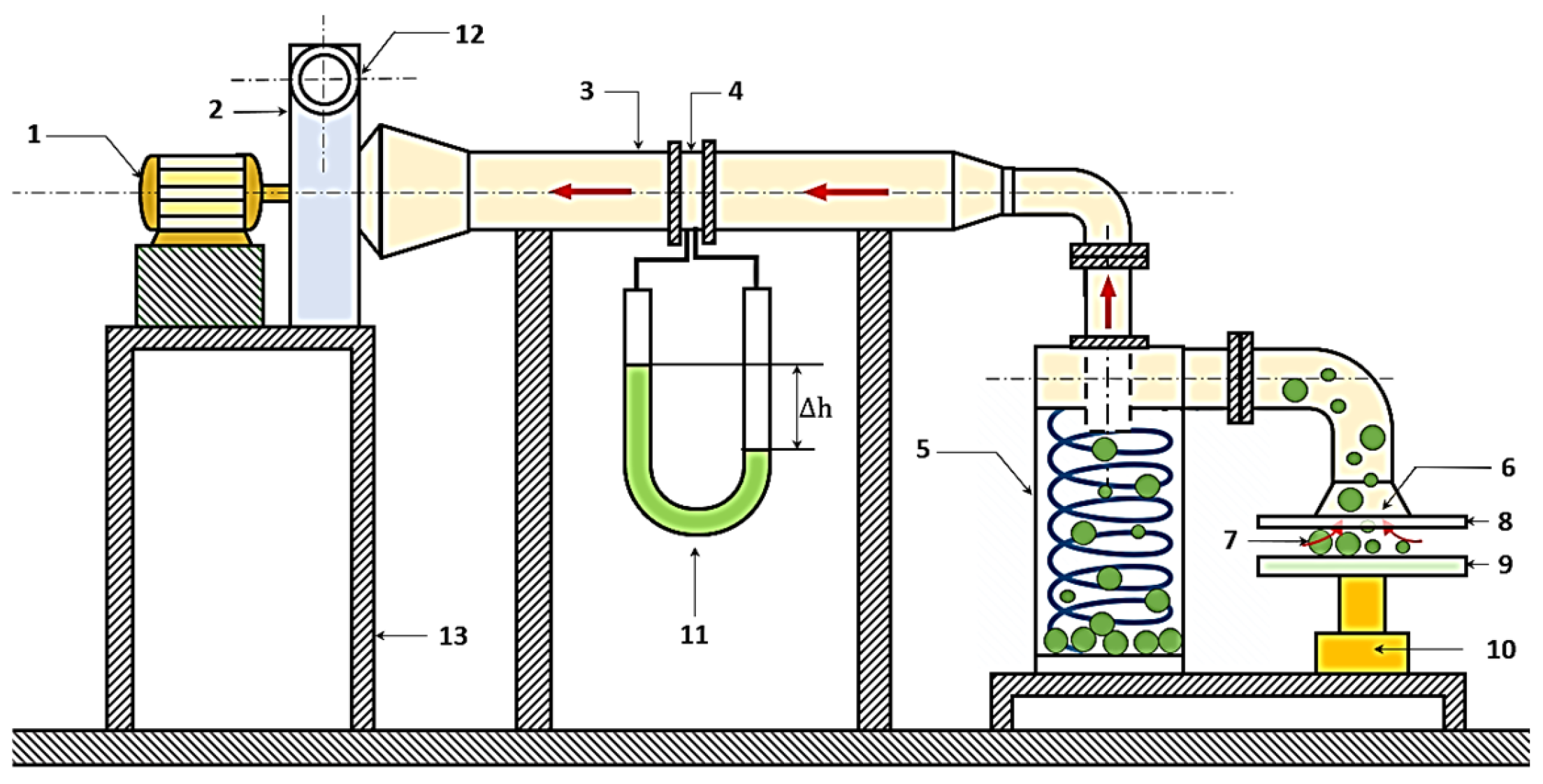
The experimental installation was designed to investigate the separation of polyethylene particles (D = 5 mm) from an air stream using a laboratory-scale cyclone separator. The system consisted of a centrifugal fan driven by an electric motor, a suction pipe with a calibrated diaphragm, a transparent observation section, and the cyclone body with a collection hopper. The airflow generated by the fan entrained the particles introduced at the inlet and carried them into the cyclone, where centrifugal forces directed them toward the wall and into the dust container.
A schematic of the setup is presented in
Figure 1, including the fan, suction pipe, diaphragm, cyclone body, observation window, and dust collector. The transparent section allowed qualitative observation of particle trajectories, which provided visual confirmation of the simulated results. The cyclone geometry introduced into the MATLAB [
22] model corresponded exactly to the experimental unit, ensuring consistency between numerical and laboratory results. The main geometric parameters are listed in
Table 1.
The airflow velocity was calibrated from diaphragm measurements. The volumetric flow rate was obtained using the relation:
where
is the volumetric flow rate,
C is the discharge coefficient,
A is the diaphragm area, Δ
p is the measured pressure drop, and
ρ is the air density. The volumetric flow rate was then converted to an average inlet velocity
, which was applied as the boundary condition in the MATLAB simulations. Typical values of
C were determined from calibration of the diaphragm under known flow conditions.
Additional constructive details of the fan and motor are not included here, as they do not directly influence the modeling framework.
Experimental measurements of differential pressure across the diaphragm provided volumetric flow rates, which were used to calibrate inlet velocity conditions in the simulation.
Figure 1 provides a clear visualization of the experimental setup, highlighting the key components involved in the dry separation process.
The relevant dimensions for the simulation are presented in
Table 1 [
23]. Additional geometric parameters, including the cyclone cone angle and the exhaust pipe diameter, are included to ensure accurate reproduction of the flow field and particle trajectories in the MATLAB simulation.
The simulation uses the physical properties of polyethylene particles (5 mm diameter, 1250 kg/m3 density) as inputs for accurate modeling of particle motion in the cyclone.
2.2. Forces Acting on a Particle in a Cyclone
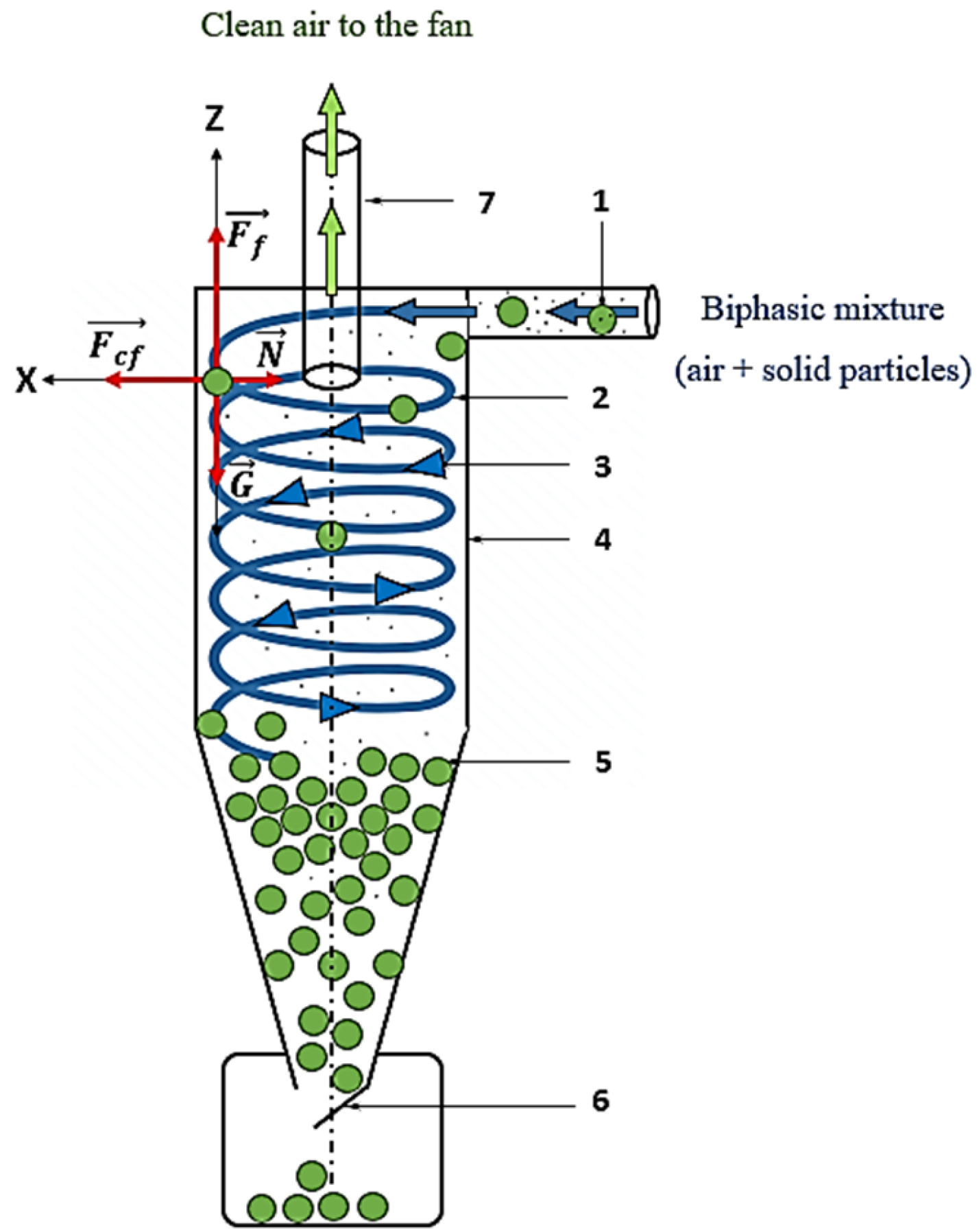
The motion of particles inside the cyclone is governed primarily by centrifugal force, wall friction, and gravity. As the gas–solid mixture enters tangentially, particles initially follow a circular trajectory driven by centrifugal force, before gradually descending in a helical path under the combined influence of drag and gravity.
Figure 2 illustrates the main forces acting on a particle: centrifugal force (
Fcf), wall friction (
Ff), gravitational force (
G), and the normal reaction force (
FN). In the horizontal direction, separation efficiency depends on whether centrifugal force overcomes wall friction, while in the vertical direction, the balance between gravity and drag (
Fd) determines the residence time before collection.
In the simplified Euler–Lagrange formulation used in this study, the particle motion equation can be written as:
where
is the particle velocity vector. Here,
represents the normal reaction force acting on the particle due to the wall constraint, balancing the perpendicular component of the centrifugal effect.
The centrifugal force is expressed as:
where
wt is the tangential velocity and
r the radial distance from the axis.
The gravitational force is:
and the drag force is:
where
C is the drag coefficient,
ρ the air density,
Ap the particle projected area,
w the particle velocity, and u the local gas velocity.
Polyethylene particles were modeled as spheres of diameter
d = 5 mm and density
ρp = 1250 kg/m
3. Their physical properties were calculated as:
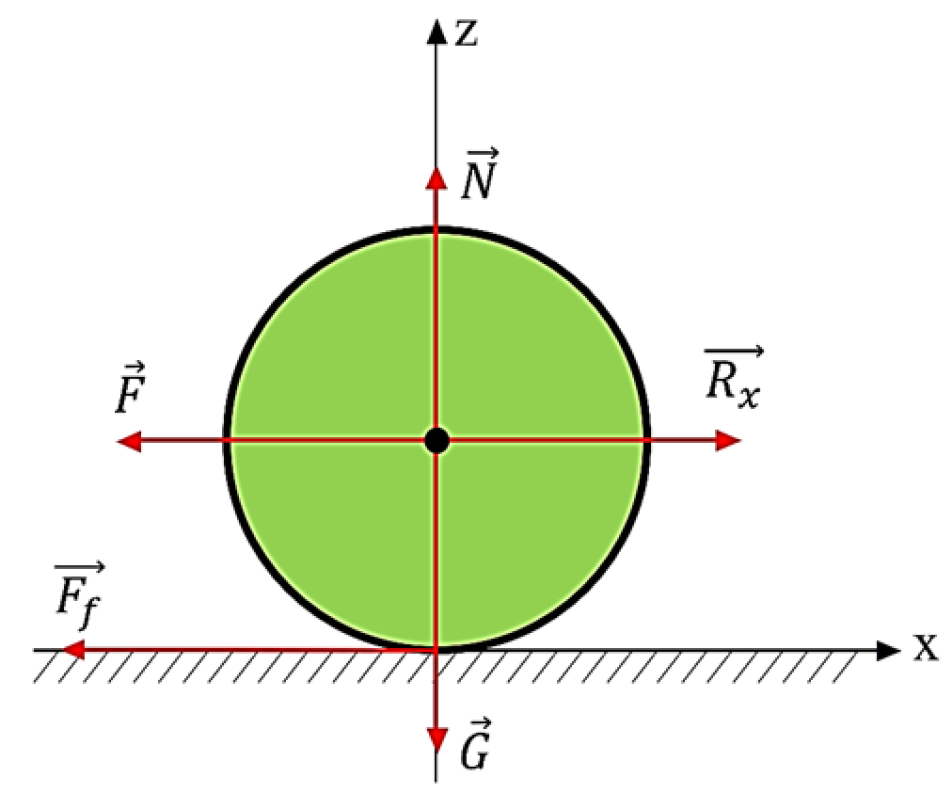
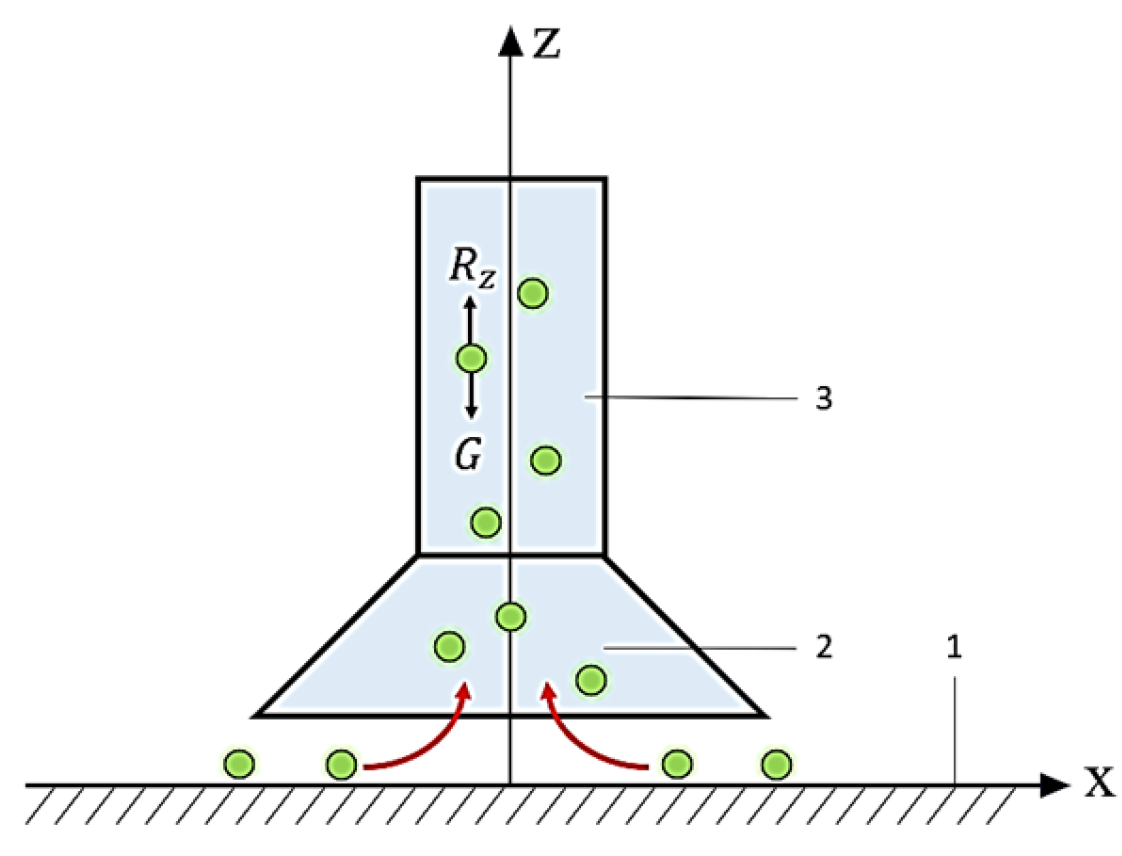
Horizontal and vertical force equilibria are shown in
Figure 3 and
Figure 4, respectively. The horizontal motion is dominated by the balance between centrifugal force and wall friction, which determines whether a particle is directed toward the wall or remains in the vortex core. The vertical motion is governed by gravity and drag forces, determining the helical descent and residence time within the cyclone.
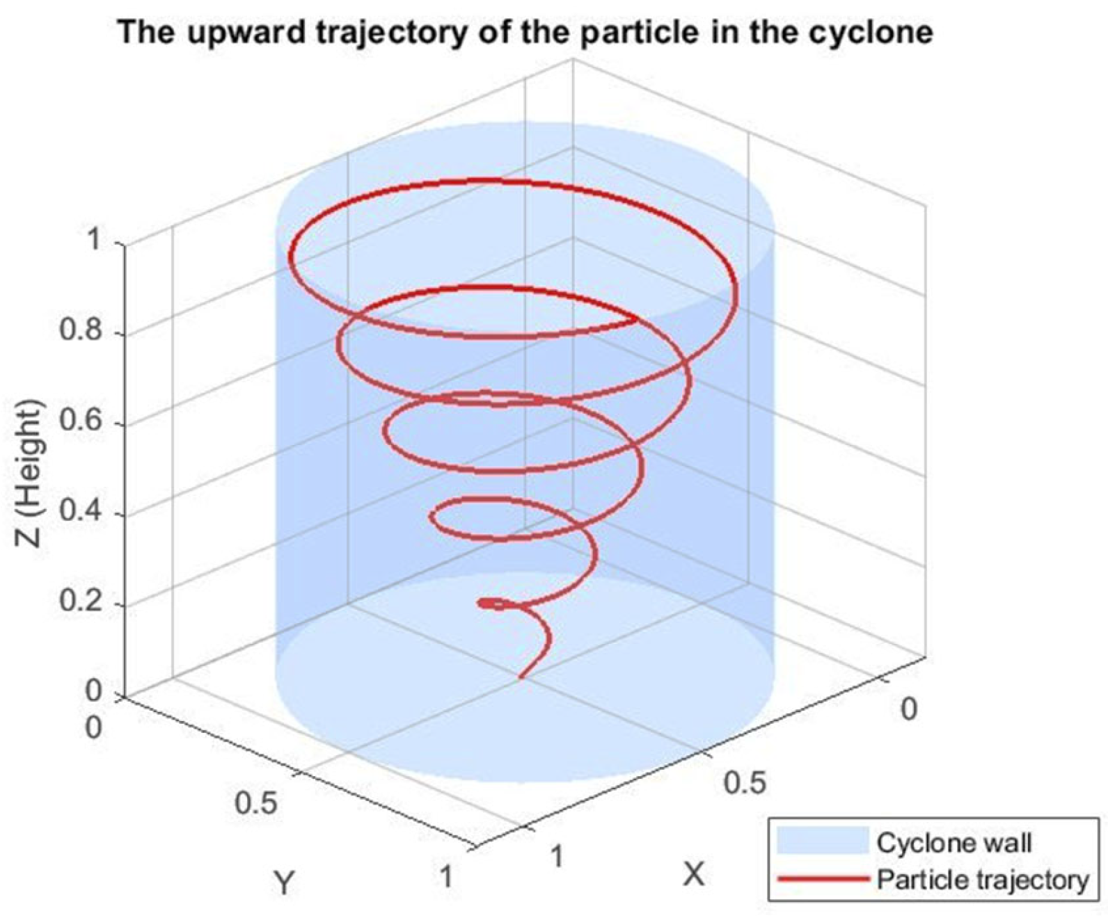
The resulting particle trajectory is illustrated in
Figure 4, where the spiral motion combines tangential velocity with a downward component until collection at the hopper.
The MATLAB implementation considered one-way coupling: the gas flow influenced particle trajectories, while particle feedback on the flow was neglected. Particle–particle interactions were not included. A sample of 100 particles was simulated for each case, sufficient to obtain representative trajectories under dilute flow conditions [
23,
24]. According to the mechanical principle of action and reaction, an opposing force
Rₓ arises, which represents the resistance to the particle’s forward motion in the horizontal direction, along the Ox axis [
25,
26].
Figure 3 shows the forces acting on the particle as it follows a circular motion with friction against the inner wall of the cyclone [
27].
Boundary conditions: inlet axial velocity
wz is set from
Figure 4 via
; a tangential component
wx initializes swirl; outlet is pressure-outlet; walls are no-slip for the gas. Particle–wall interaction uses kinetic impact with Coulomb friction (sliding
μ1 = 0.01, rolling
μ2 = 0.03 as in [
28,
29]).
2.3. The Connection of Cyclones Used in Dust Removal Plants
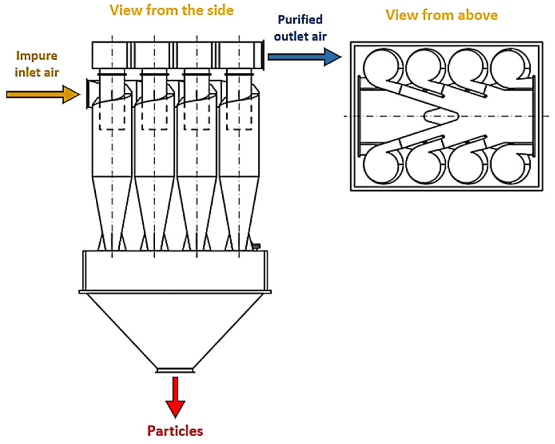
Cyclones are often combined in multi-unit networks to enhance either collection efficiency or throughput capacity, depending on industrial requirements [
23,
30]. Two common configurations are series and parallel arrangements.
In the series configuration, the same gas–solid flow passes sequentially through two cyclones (
Figure 5). The first stage captures most of the particles, while the second removes part of the remaining fraction. This increases overall efficiency but also leads to a higher total pressure drop. Due to upstream losses, the velocity entering the second cyclone is slightly reduced, which influences the centrifugal force acting on particles and limits the gain in separation performance [
31]. In a cyclone, the normal force must be greater than the particle’s weight for efficient separation, as is the case here [
32,
33].
In the parallel configuration, the inlet flow is divided between two identical cyclones (
Figure 6). Each unit processes a smaller portion of the total flow, resulting in reduced velocity per cyclone and lower pressure losses. While the efficiency of each cyclone remains close to that of a single unit, the total throughput is almost doubled, making this configuration suitable when increased capacity is required without a significant energy penalty.
In both cases, the MATLAB simulations applied the same particle size and density as in the single cyclone experiments. For the parallel configuration, the inlet flow was split evenly between the two branches, while in the series arrangement, the downstream cyclone received the reduced velocity field from the upstream stage. These assumptions approximate realistic operating conditions and allow predictive comparisons of the two configurations.
3. Results
The MATLAB model was first validated against the experimental measurements for the single cyclone.
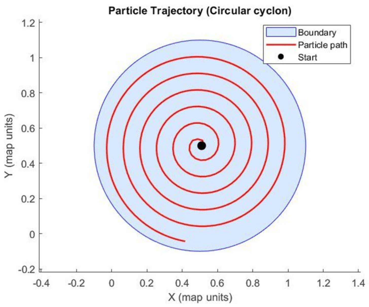
Figure 7 shows representative simulated particle trajectories, which were consistent with visual observations through the transparent window of the experimental rig. Particles followed helical paths toward the cyclone wall under centrifugal force, drag, and gravity, with a fraction escaping through the vortex finder.
Quantitative comparisons between measured and simulated results confirmed the accuracy of the simplified Euler-Lagrange model. For Δh = 15 mmH
2O, the measured pressure drop was 150 Pa, while the simulation predicted 142 Pa (error 5.3%). The corresponding separation efficiency measured was ~76%, compared with ~78% numerically (error 2.6%). These deviations remained below 6% across the tested conditions, demonstrating good agreement (
Figure 8,
Table 2).
Experimental values are shown where available; simulated values were obtained using the developed model under identical inlet conditions. The separation efficiency for 5 mm particles is lower than typical values for micron-sized particles due to the larger particle size and moderate residence time in the lab-scale cyclone.
After validating the model, it was applied to explore the behavior of series and parallel configurations.
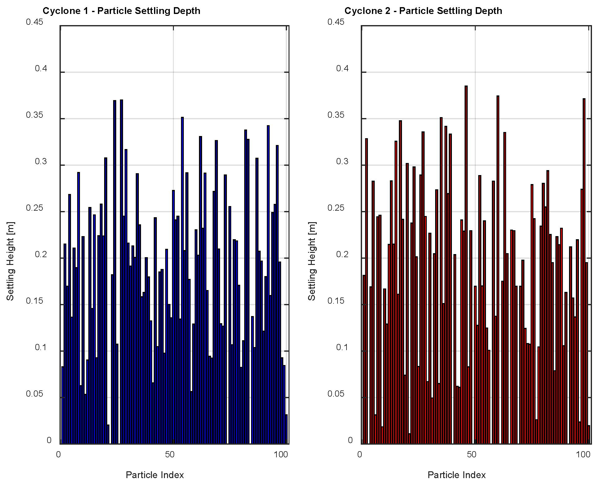
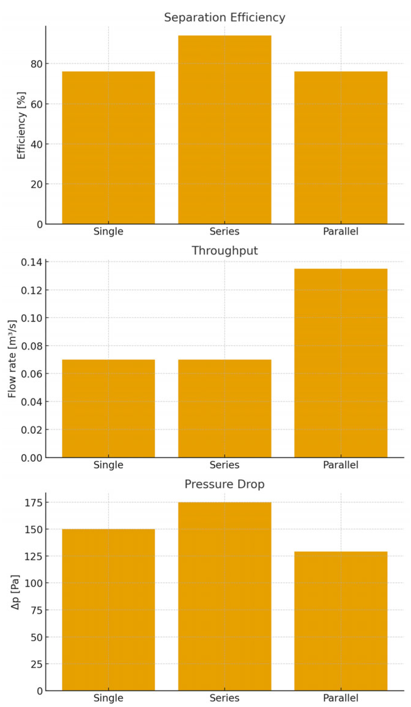
Figure 9 illustrates typical simulated trajectories in the multi-cyclone arrangements. In the series configuration, particles that bypass the first cyclone enter the second, leading to an overall efficiency increase up to ~94%. However, the total pressure drop increased by ~17% compared to the single cyclone, due to additional wall friction and turbulence losses. Importantly, the velocity entering the second cyclone was slightly reduced because of the pressure drop across the first unit, limiting the gain in performance.
In the parallel configuration, the total inlet flow was divided between two identical cyclones. Each unit processed half of the flow, resulting in lower velocities per cyclone but reduced pressure drop. The overall throughput nearly doubled compared to the single cyclone, while separation efficiency remained within 2% of the single cyclone case. The pressure drop decreased by ~14%, confirming that the parallel arrangement provides higher capacity with moderate efficiency (
Figure 10).
A comparative summary is presented in
Figure 11. The single cyclone offered balanced performance with moderate efficiency and pressure drop. The series configuration maximized efficiency but at the cost of higher Δ
p, whereas the parallel arrangement increased capacity and lowered Δ
p with little change in efficiency.
It should be emphasized that cyclone operation is strongly dependent on inlet velocity. In the present setup, effective separation of 5 mm polyethylene particles was achieved in the range of 8–12 m/s, in line with reported literature values [
9,
10,
34,
35]. Below this range, centrifugal force was insufficient for collection, while at higher velocities, turbulence caused particle re-entrainment and efficiency losses. These observations highlight the importance of operating conditions when interpreting predictive simulations.
In the setup, the bulk inlet velocity corresponding to a volumetric flow rate of 0.07 m3/s through a 104 mm diameter pipe was approximately 8.2 m/s. Local velocity components used in the MATLAB model were imposed as wx = 1.74 m/s and wz = 1.2 m/s, based on diaphragm calibration. For the studied 5 mm polyethylene spheres, centrifugal force largely exceeded gravity even at these local velocities. For example, at wt = 1.74 m/s, the ratio Fcf/mg was about 6, while at the bulk velocity of 8.2 m/s, the ratio reached ~130. This confirms that the selected velocity range is appropriate for efficient separation.
Effective separation was observed for bulk velocities between 8–12 m/s, consistent with literature values [
9,
10]. Below this threshold, centrifugal acceleration became insufficient for particle capture, while at higher velocities turbulence effects promoted particle re-entrainment.
The present results agree qualitatively with CFD–DEM studies [
11,
12,
13], although the MATLAB framework neglects particle–particle interactions and turbulence fluctuations. This comparison shows that, despite its simplifications, the MATLAB model reproduces the dominant trends in separation efficiency, pressure drop, and particle trajectories observed in high-fidelity CFD–DEM simulations. Therefore, the model provides reliable predictive trends suitable for preliminary design and parametric studies at significantly lower computational cost. The multi-cyclone results should therefore be regarded as predictive trends rather than experimentally validated outcomes.
4. Discussion
The experimental validation confirmed that the simplified Euler–Lagrange MATLAB model can reproduce the aerodynamic performance of a single cyclone with deviations of less than 6% for both pressure drop and efficiency. This result is consistent with previous works where simplified models, once calibrated, were shown to capture the dominant physics of centrifugal separation [
23,
24].
The simulation results were validated against laboratory measurements under the same inlet velocity and particle size conditions. The deviation between simulated and experimental values for separation efficiency and pressure drop did not exceed 5%, confirming the accuracy of the MATLAB-based Euler–Lagrange model. The observed separation efficiency of 76% for 5 mm particles in the single cyclone is consistent with expectations for millimeter-sized particles in a lab-scale cyclone. Larger particles experience inertial effects, but due to the moderate tangential velocities and limited residence time, not all particles reach the cyclone wall for collection. In contrast, industrial cyclones handling micron-sized particles achieve higher efficiencies due to shorter particle relaxation times and enhanced deposition on the walls. This explains the lower efficiency observed in our study compared to typical catalytic cracking applications.
Extending the model to multi-cyclone configurations provided only predictive trends, as no experimental data were available for these arrangements. In the series configuration, efficiency increased but the pressure drop penalty was significant, reflecting the expected trade-off between separation performance and energy demand. In the parallel configuration, throughput nearly doubled while maintaining comparable efficiency and reducing Δ
p, which suggests potential advantages in applications requiring higher capacity. These outcomes align with tendencies reported in CFD–DEM simulations [
11,
12,
13], confirming that the simplified MATLAB tool can replicate general trends even though it lacks full physical fidelity.
Operating conditions play a critical role in cyclone performance. Both experimental observations and simulations indicated that efficient separation of 5 mm polyethylene particles occurs in the inlet velocity range of 8–12 m/s. Below this threshold, centrifugal force is insufficient, whereas above it, turbulence promotes re-entrainment. Such velocity-dependent behavior has been widely reported in the literature [
9,
10], and the present results support these findings.
The main limitations of the study arise from the simplifications adopted: particle–particle interactions were neglected, turbulence was treated only indirectly, and simulations were limited to 100 monodisperse particles. These assumptions restrict the applicability of the model to dilute and idealized conditions. Nevertheless, the MATLAB framework proved valuable as a low-cost, transparent tool that complements more advanced CFD–DEM approaches such as XDEM [
21]. While the latter offer detailed resolution of turbulence and collisions, they are computationally expensive, whereas the present model provides fast insights that can assist preliminary design or educational use.
5. Conclusions
This study investigated the performance of cyclone separators by combining laboratory experiments with a simplified MATLAB-based Euler–Lagrange simulation framework. The experimental validation performed on a single cyclone demonstrated that the model could reproduce both pressure drop and separation efficiency with deviations below 6%. This agreement confirms that, despite its simplified assumptions, the MATLAB implementation is able to capture the essential mechanisms of particle separation in cyclone devices.
The extension of the model to series and parallel cyclone arrangements provided only predictive trends, since these configurations were not experimentally tested. When compared to high-fidelity CFD–DEM studies, the trends predicted by the simplified model are consistent in terms of relative efficiency gains, pressure drop changes, and throughput variations between configurations. This highlights the value of the simplified approach for rapid evaluation of multi-cyclone performance while maintaining reasonable accuracy. The series connection increased overall efficiency to approximately 94%, but this came at the cost of a higher total pressure drop, which limits its practical benefit. In contrast, the parallel configuration nearly doubled the total throughput while maintaining efficiency close to that of the single cyclone and simultaneously reducing pressure losses. These findings indicate clear trade-offs between efficiency, capacity, and energy demand that must be considered in cyclone network design.
An important outcome of both experiments and simulations was the identification of an optimal inlet velocity range for the studied particles. Stable and efficient separation of 5 mm polyethylene spheres was achieved between 8 and 12 m/s, in line with results reported in the literature. At lower velocities, centrifugal forces were insufficient to drive particles toward the wall, while at higher velocities turbulence promoted re-entrainment and reduced collection efficiency.
The limitations of the present study must also be emphasized. The model neglected particle–particle interactions, assumed monodisperse particles, and used a simplified treatment of turbulence. These restrictions confine its applicability to dilute flows and idealized operating conditions. Nevertheless, the framework proved to be a transparent and computationally efficient complement to high-fidelity CFD–DEM simulations such as XDEM, offering fast insights that are particularly valuable for preliminary design and educational purposes.
Future work will extend the validation to multi-cyclone systems and consider more realistic conditions, including polydisperse particle distributions, larger particle numbers, and advanced turbulence models such as RANS and LES. These improvements will enhance predictive accuracy and allow the methodology to be applied to a wider range of industrial gas–solid separation processes.
Author Contributions
Conceptualization, M.C., N.B. and C.D.; methodology, M.C., A.C. and C.D.; software, M.C. and D.D.; validation, A.C., D.T. and C.D.; formal analysis, M.C. and M.O.; investigation, M.C. and N.B.; resources, C.D. and B.I.; data curation, D.D. and DT; writing—original draft preparation, B.I. and M.O.; writing—review and editing, M.C., A.C. and B.I.; visualization, C.D., D.D. and D.T.; supervision, M.C. and N.B.; project administration, M.C. and C.D.; funding acquisition, M.C. and C.D. All authors have read and agreed to the published version of the manuscript.
Funding
This research received no external funding.
Institutional Review Board Statement
Not applicable.
Informed Consent Statement
Not applicable.
Data Availability Statement
The original contributions presented in this study are included in the article. Further inquiries can be directed to the corresponding authors.
Conflicts of Interest
The authors declare no conflicts of interest.
Abbreviations
The following abbreviations are used in this manuscript:
| Symbol | Description | Unit |
| D | Particle diameter | mm |
| r | Radial distance from cyclone axis | m |
| ω | Angular velocity | rad·s−1 |
| mp | Mass of the particle | kg |
| Fc | Centrifugal force | N |
| Fg | Gravitational force | N |
| FN | Normal reaction force | N |
| Fd | Drag force | N |
| Ff | Wall friction force | N |
| ρp | Particle density | kg·m−3 |
| ρf | Fluid density (air) | kg·m−3 |
| C | Drag coefficient | - |
| Ap | Particle projected area | m2 |
| μ | Dynamic viscosity | Pa·s |
| Re | Reynolds number | – |
| w | Particle velocity | m·s−1 |
| t | Time | s |
| θ | Local inclination/trajectory angle of the particle (angle between radial direction and particle velocity | rad//° |
References and Note
- Park, D.; Go, J.S. Design of Cyclone Separator Critical Diameter Model Based on Machine Learning and CFD. Processes 2020, 8, 1521. [Google Scholar] [CrossRef]
- Sommerfeld, M.; Taborda, M.A. Understanding solid particle transport in a gas cyclone separator. Int. J. Multiph. Flow 2024, 181, 104992. [Google Scholar] [CrossRef]
- Venkatesh, S.; Sivapirakasam, S.P.; Sakthivel, M.; Ganeshkumar, S.; Prabhu, M.M.; Naveenkumar, M. Experimental and numerical investigation in the series arrangement square cyclone separator. Powder Technol. 2021, 383, 93–103. [Google Scholar] [CrossRef]
- Malahayati, N.; Darmadi, D.; Putri, C.A.; Mairiza, L.; Rinaldi, W.; Yunardi, Y. Comparative performance analysis between conventional and square cyclones for solid Particle-Gas Separation: A review. Mater. Today Proc. 2022, 63 (Suppl. S1), S318–S325. [Google Scholar] [CrossRef]
- Bregolin, E.; Danieli, P.; Masi, M. Collection Efficiency of Cyclone Separators: Comparison between New Machine Learning-Based Models and Semi-Empirical Approaches. Waste 2024, 2, 240–257. [Google Scholar] [CrossRef]
- Zhou, F.; Guo, Y.; Qian, H.; Fu, S.; Yuan, H. Effect of wall roughness on particle deposition on the outer wall of the vortex finder in a cyclone separator. Ad. Powder Technol. 2024, 35, 104428. [Google Scholar] [CrossRef]
- Dziubak, T.; Dziubak, S.; Tomaszewski, M. Numerical study of the effect of axial cyclone inlet velocity and geometrical parameters on separation efficiency and pressure drop. Powder Technol. 2023, 427, 118692. [Google Scholar] [CrossRef]
- Yu, G.; Dong, S.; Yang, L.; Yan, D.; Wei, K.Y.; Wang, B. Experimental and numerical studies on a new double-stage tandem nesting cyclone. Chem. Eng. Sci. 2021, 236, 116537. [Google Scholar] [CrossRef]
- Wang, J.; Zhang, J. Investigation of velocity and magnetic field effects in an improved electrostatic cyclone precipitator for removal of submicron particles. Fuel 2025, 379, 133035. [Google Scholar] [CrossRef]
- Wang, W.; Zhao, X.; Bai, X.; Ma, X.-L.; Lin, W.; Yu, J.-Y. Investigation of factors affecting oil-water separation efficiency in micro-bubble micro-cyclonic flow air flotation. J. Water Process Eng. 2024, 67, 106094. [Google Scholar] [CrossRef]
- Dziubak, S.; Małachowski, J.; Dziubak, T.; Tomaszewski, M. Numerical studies of an axial flow cyclone with ongoing removal of separated dust by suction from the settling tank. Chem. Eng. Res. Des. 2024, 208, 29–51. [Google Scholar] [CrossRef]
- Dziubak, S.; Tdeusz Dziubak, T. Experimental study of an axial flow cyclone with ongoing dust removal from a settling tank. Chem. Eng. Process.-Process Intensif. 2025, 209, 110167. [Google Scholar] [CrossRef]
- Misiulia, D.; Antonyuk, S.; Andersson, A.G.; Lundström, T.S. High-efficiency industrial cyclone separator: A CFD study. Powder Technol. 2020, 364, 943–953. [Google Scholar] [CrossRef]
- Venkatesh, S.; Sakthivel, M.; Saranav, H.; Saravanan, N.; Rathnakumar, M.; Santhosh, K.K. Performance investigation of the combined series and parallel arrangement cyclone separator using experimental and CFD approach. Powder Technol. 2020, 361, 1070–1080. [Google Scholar] [CrossRef]
- Ravi Shastri, R.; Wasilewski, M.; Brar, L.S. Analysis of the novel hybrid cyclone separators using large-eddy simulation. Powder Technol. 2021, 394, 951–969. [Google Scholar] [CrossRef]
- Zhou, Y.; Liu, W.; Zhu, X.; Liu, Y.; Liu, B.; Zhu, J.; Zhang, H. Air deflector-augmented cyclone design for superior powder coating particle-size distribution and performance. Prog. Org. Coat. 2025, 200, 108967. [Google Scholar] [CrossRef]
- Liang, Y.; Cheng, T.; Li, Q.; Liu, J.; Li, Q.; Li, J.; Ma, S.; Jiang, X.; Wang, H.; Fu, P. CFD-DEM simulation of cyclone self-rotation drying: Particle high-speed self-rotation and heat transfer. Energy 2024, 290, 1130277. [Google Scholar] [CrossRef]
- Sonawane, C.R.; Dhanorkar, M.; Mishra, I.; Kirdat, A.; Bhatwadekar, S.; Sawant, R.; Pandey, A. Numerical simulation of hydro-cyclone separator used for separation of highly dense suspended particulate matter. Mater. Today Proc. 2022, 59 Pt 1, 85–92. [Google Scholar] [CrossRef]
- Constantin, M.; Dobre, C.; Oprea, M. Thermodynamic Analysis of Oxygenation Methods for Stationary Water: Mathematical Modeling and Experimental Investigation. Thermo 2025, 5, 28. [Google Scholar] [CrossRef]
- Wójtowicz, R.; Wolak, P.; Wójtowicz-Wróbel, A. Numerical and Experimental Analysis of Flow Pattern, Pressure Drop and Collection Efficiency in a Cyclone with a Square Inlet and Different Dimensions of a Vortex Finder. Energies 2021, 14, 111. [Google Scholar] [CrossRef]
- Peters, B.; Baniasadi, M.; Baniasadi, M.; Besseron, X.; Donoso, A.-E.; Mohseni, M.; Pozzetti, G. XDEM multi-physics and multi-scale simulation technology: Review of DEM–CFD coupling, methodology and engineering applications. Particuology 2019, 44, 176–193. [Google Scholar] [CrossRef]
- MathWorks. MATLAB Release 2023a; The MathWorks, Inc.: Natick, MA, USA, 2023. [Google Scholar]
- Guizani, R.; Mhiri, H.; Bournot, P. Numerical Investigation of the Vortex Breaker for A Dynamic Separator using Computational Fluid Dynamics. J. App. Fluid Mech. 2023, 16, 1099–1107. [Google Scholar]
- Ciobanu, R.; Arhip, G.; Donțu, O.; Rizescu, C.I.; Grămescu, B. Additive Manufacturing Meets Gear Mechanics: Understanding Abrasive Wear Evolution in FDM-Printed Gears. Polymers 2025, 17, 1810. [Google Scholar] [CrossRef] [PubMed]
- Dobre, C.; Petrescu, S.; Constantin, M. The direct method from finite speed thermodynamics used for isentropic efficiency evaluation of reversed quasi-carnot irreversible cycles. UPB Sci. Bull. Ser. D 2021, 83, 83–96. [Google Scholar]
- Scientific research contract No. 17-8-6/18.08.1998, I.P.B. on the topic “Solutions for reducing coal dust concentrations in power plants to the level of maximum permitted concentrations and dispersions”, Beneficiary I.E. Borzești.
- Avramescu, A. The Importance and Necessity of New Bio-Based Materials in Industrial Design. Mater. Plast. 2023, 60, 121–127. [Google Scholar] [CrossRef]
- Băran, N.; Căluşaru, I.M.; Mateescu, G. Influence of the architecture of fine bubble generators on the variation of the concentration of oxygen dissolved in water. UPB Sci. Bull. Ser. D 2013, 75, 225–236. [Google Scholar] [CrossRef]
- Bratu, E. Operations and Equipment in the Chemical Industry; Technical Publishing House: Bucharest, Romania, 1969; Volumes 1 and 2. (In Romanian) [Google Scholar]
- Petrescu, S.; Dobre, C.; Costea, M.; Dobrovicescu, A.; Tîrcǎ-Dragomirescu, G. Entropy generation analysis and COP evaluation for a reversed quasi-Carnot cycle (refrigeration machine) by using the direct method from finite speed thermodynamics. UPB Sci. Bull. Ser. D 2012, 74, 117–136. [Google Scholar]
- Căluşaru, I.M.; Băran, N.; Pătulea, A.L. The influence of the constructive solution of fine bubble generators on the concentration of dissolved oxygen in water. Ad. Mat. Res. 2012, 538–541, 2304. [Google Scholar] [CrossRef]
- Barua, S.; Batcha, M.F.M.; Mohammed, A.N.; Saif, Y.; Al-Alimi, S.; Al-fakih, M.A.M.; Zhou, W. Numerical Investigation of Inlet Height and Width Variations on Separation Performance and Pressure Drop of Multi-Inlet Cyclone Separators. Processes 2024, 12, 1820. [Google Scholar] [CrossRef]
- Constantin, M.; Dobre, C.; Oprea, M. Mathematical Modeling of Oxygen Transfer Using a Bubble Generator at a High Reynolds Number: A Partial Differential Equation Approach for Air-to-Water Transfer. Inventions 2024, 9, 76. [Google Scholar] [CrossRef]
- Căluşaru, I.M.; Băran, N.; Costache, A. The determination of dissolved oxygen concentration in stationary water. App. Mec. Mat. 2013, 436, 233. [Google Scholar] [CrossRef]
- Ulusoy, U. A Review of Particle Shape Effects on Material Properties for Various Engineering Applications: From Macro to Nanoscale. Minerals 2023, 13, 91. [Google Scholar] [CrossRef]
| Disclaimer/Publisher’s Note: The statements, opinions and data contained in all publications are solely those of the individual author(s) and contributor(s) and not of MDPI and/or the editor(s). MDPI and/or the editor(s) disclaim responsibility for any injury to people or property resulting from any ideas, methods, instructions or products referred to in the content. |
© 2025 by the authors. Licensee MDPI, Basel, Switzerland. This article is an open access article distributed under the terms and conditions of the Creative Commons Attribution (CC BY) license (https://creativecommons.org/licenses/by/4.0/).
