Article

Analysis of Performance of Bone-Anchored Implants for Amputation Limb Prostheses

by
Riyam Basim Al-Tameemi
1,2,
Hashem Mazaheri
1,*,
Jumaa Salman Chiad
3 and
Mahdi Shaban
1
1
Department of Mechanical Engineering, Faculty of Engineering, Bu-Ali Sina University, Hamedan P.O. Box 651754161, Iran
2
Imam Alkadhim University College, Baghdad 14522, Iraq
3
Al-Karkh University of Science, Baghdad 1001, Iraq
*
Author to whom correspondence should be addressed.
Appl. Mech. 2025, 6(4), 77; https://doi.org/10.3390/applmech6040077
Submission received: 2 July 2025 / Revised: 4 August 2025 / Accepted: 31 August 2025 / Published: 17 October 2025

Abstract

Bone-anchored implants have transformed prosthetic technology by providing a promising alternative to traditional socket-based prostheses through enhanced stability, comfort, and natural limb functionality. These advancements result from developments in osseointegration techniques, improved surgical methods, and innovative implant materials. To address current limitations, continued research remains essential to enhance safety and effectiveness, thereby promoting wider adoption of these advanced prosthetic solutions. This study focuses on modeling bone-anchored implants for limb prostheses in amputees. The research evaluates structural behavior and performance of osseointegrated implants under various conditions while optimizing implant design. The investigation examines different materials including aluminum, Ti-6Al-4V, and Ti-6Al-4V coated with 10 µm platinum. Additionally, implants of different lengths (207 mm, 217 mm, and 197 mm) were analyzed. The results indicate that Ti-6Al-4V and Ti-6Al-4V coated with ten µm platinum reduce stress by 46% and 65%, respectively. Ti-6Al-4V coated with platinum demonstrates the lowest equivalent stress, highlighting the coating’s effectiveness. Furthermore, the coated implant exhibits the lowest deformation—22.92% less than aluminum and 5.13% less than uncoated Ti-6Al-4V. Shorter implant lengths reduce deformation through increased stiffness, whereas longer implants, such as the 217 mm length display greater deformation due to enhanced flexibility.

1. Introduction

Osseointegrated implants serve as medical devices that establish a direct structural and functional connection between an artificial limb or prosthesis and the existing bone. These implants primarily assist individuals who have undergone limb amputation and need a reliable attachment point for their prosthetic limb [1]. Osseointegration fuses the implant with the bone, enhancing load transfer and mobility. A titanium fixture promotes bone ingrowth, while an abutment connects to the prosthetic limb. Transfemoral amputation affects mobility and quality of life, requiring assistive devices, rehabilitation, and psychological support for improved quality of life [2]. Stress and strain analysis in bone-anchored implants for amputation prostheses is essential for understanding how these implants interact with the surrounding bone tissue and the mechanical forces exerted on them. Stress refers to the internal resistance or force within a material when subjected to external loads [3]. For bone-anchored implants, stress may occur at various locations, including the implant–bone interface, the implant body, and the adjacent bone. Stress distribution depends on factors such as implant design, the material properties of the implant and bone, and the applied loads. Analyzing strain in bone-anchored implants is crucial for optimizing design, enhancing stability, and improving prosthetic functionality. Osseointegration refers to the direct structural and functional connection between living bone and the surface of a biocompatible implant, typically composed of materials like titanium. It refers to the direct structural and functional connection between the implant and the bone. Osseointegration has significant benefits in the field of prosthetics and implantology [4]. Osseointegration enhances prosthetic limb stability by offering a more secure attachment compared to traditional socket-based prostheses, reducing discomfort and improving control. This direct skeletal connection improves load transfer, gait patterns, and energy efficiency, leading to better mobility. Users report better connection and control, allowing for effective performance in daily activities and sports. Osseointegrated implants also provide a wider range of motion and demonstrate durability, decreasing the need for frequent adjustments and ensuring long-term reliability. Load transfer mechanisms in osseointegrated implant systems describe how forces transmit between the implant and the surrounding bone. These mechanisms play a crucial role in maintaining implant stability and longevity by promoting efficient load distribution and minimizing stress concentrations. Taylor and Agar [5] emphasized the evolution of prosthodontics for dental implants, shaped by lessons from the past 20 years. It highlighted the role of osseointegration in advancing implant prosthodontics, guiding future clinical practices and research to enhance patient care. Stenlund et al. [6] demonstrated that osseointegrated transfemoral amputation prostheses are viable alternatives to conventional socket prostheses, facilitating prosthetic use. Koehler [7] compared force and moment readings from an iPecsTM load cell with those from a standard gait analysis lab during in-field testing of a transtibial amputee. Despite favorable comparisons, sensitivity analysis highlighted the need for accurate axis identification. Proctor and Sajewicz [8] compared implant designs for bone-anchored prostheses, emphasizing that the suggested design improved load-bearing capacity. Caution is needed with press fit solutions to maintain stability, while the proposed implant shows promise for medical applications. Al-Maliky and Chiad [9] looked inside the prosthetic knee’s four-bar 3R20 mechanism. The findings indicated that when orientation angles were 85.5° and 105.4° and ICR coordinates were 0.560 mm and 77.388 mm for X and Y correspondingly, the highest stress was generated at the loading response phase with 226.93 Mpa at the root area between the prosthetic knee and socket. Frossard et al. [10] demonstrated the loads placed on transfemoral osseointegrated implants by bone-anchored prostheses equipped with the cutting-edge SSUR microprocessor-controlled Rheo Knee XC and energy-storing and -returning Pro-Flex XC or LP foot during five standardized everyday activities. Guo et al. [11] reviewed modification methods to improve Ti implants’ soft tissue integration, addressing Soft Tissue Integration (STI) challenges with Ti-based implants. It emphasized advancements in nanoengineered implants with TiO2 nanotubes and nanopores, emphasizing clinical translation. The Osseointegrated Prostheses for the Rehabilitation of Amputees (OPRA) system’s smooth abutment surface minimizes skin interface friction. Heimke et al. [12] reviewed developed ceramics in knee arthroplasty. It was possible to design, produce, and test-implant a total knee replacement made of this incredibly wear-resistant modified alumina ceramic in a human cadaver knee because the specifications of a recently developed modification of an alumina ceramic fall within the desired range and improve by a factor of two for nearly all relevant properties. Viceconti et al. [13] predicted the implant’s long-term secondary stability from initial post-operative stability. The model demonstrated unique solutions for all initial conditions, with discrepancies between the continuous and finite-state models being minimal (less than 4%). Thus, the finite-states model is recommended for asymptotic conditions and the continuous model for adaptive process evolution. Helgason et al. [14] contrasted the finite element technique pre-processors for the human femur that were based on geometry and those that were voxel-based. By measuring the primary stress with strain gauges, the models were experimentally validated. The findings suggested that the validity of voxel-based modeling was comparable to the validity of geometry-based modeling concerning the major stress. Voxel-based meshing was found to make it simple to interface with Computer Tomography (CT) images and may help develop clinically useful FEM technology. Tillander et al. [15] looked at the frequency and appearance of infection problems and explored the osseointegrated titanium implants for limb prosthesis attachments. Regardless of frequent colonization by potentially dangerous bacteria like Staphylococcus aureus and bacteria linked to biomedical device infections like coagulase negative staphylococci near the skin–implant interface, this titanium implant system for bone-anchored prostheses rarely caused infections that resulted in disability or implant removal. Brånemark et al. [16] compared the biomechanical and histological response to titanium implants that had been partially laser-modified to those that had been machined. Different fracture mechanisms for the two surfaces were shown. Tomaszewski et al. [17] examined the long-term periprosthetic bone alterations around two distinct types of fixation implants utilizing two different beginning situations, namely the usual implantation after a significant amount of socket prosthesis usage and the immediate post-amputation implantation. Frossard et al. [18] reviewed trends, opportunities, and challenges for the generation of devices to diagnose the residuum health of individuals suffering from limb loss. Pitkin [19] observed the design elements of implants for limb prostheses that attach directly to the skeleton. A construct was implanted into an amputee’s residuum bone and protruded out of the residuum’s skin in the Direct Skeletal Attachment (DSA) of limb prosthesis. Tsikandylakis et al. [20] researched transhumeral amputees’ osseointegrated implants and showed an 83% 5-year survivability and 38% treatable infection rate, suggesting a compelling alternative to traditional prostheses. Especially for short residual humerus cases, it may be superior, but further comparative and long-term studies are needed to confirm this. Van Eck and McGough [21] talked about whether it would be possible to connect osseointegrated implant to human nerve stumps. In theory, the idea was clear-cut and easy to understand. Our challenges were exacerbated by post-amputation changes to the central and peripheral nervous systems, the need for an interface that demonstrates both electrochemical and mechanical biocompatibility, the risk of nerve damage, the requirement to record nerve impulses over an extended period, and the requirement to stimulate sensory neurons. Muderis et al. [22] examined the Integral Leg Prosthesis process on the first 100 patients to evaluate the implant design, surgical protocols, and functional testing of this novel technology. By re-engineering the implant, surgical revisions brought on by infection have decreased from 29% with the original implant design to 7%. Li and Lindeque [23] discussed the Swedish program for transfemoral amputation rehabilitation based on the use of bone-anchored prostheses for osseointegration. The patient-centered assessment, surgical method, and post-operative rehabilitation plan were all covered in detail by the authors. Using bone-anchored prostheses, the results of a prospective study of transfemoral amputees were described. Prochor and Sajewicz [24] optimized thread shape for implants in limb prosthetics, minimizing stress peaks by adjusting thread characteristics. Shallow threads generated a single stress peak, while symmetrical and asymmetrical threads produced multiple peaks. Reducing the rounding arc by 0.2 mm improved biomechanical performance, enhancing implant stability. Brånemark et al. [25] discovered that patients who underwent transfemoral amputations showed considerable improvements in patient-reported outcome measures during a 5-year follow-up, although increases in deep infections and mechanical problems were alarming. Wang and Lynch [26] gave a thorough summary of the several elastic stress wave techniques previously investigated for in situ evaluation of Osseointegrated implants. Prochor et al. [27] linked stress-shielding in bone-anchored prostheses to bone–implant stability, examining design shape and material stiffness. Threaded implants, despite 4% more distal femur bone loss, showed 5% less overall bone loss than press-fit designs, offering greater stability in bone–implant coupling. Thesleff et al. [28] numerically investigated a screw-based bone-anchored implant under ambulatory loads. Increasing cortical thickness from 2 mm to 5 mm decreased highest longitudinal stress by 36–44%. Reducing thread depth from 1.5 mm to 0.75 mm lowered stress by up to 22%, while increasing thread root radius had a smaller effect. Hagberg et al. [29] explored osseointegrated prostheses for individuals who had transfemoral amputations as a kind of rehabilitation. The introduction of a prospective, ten-year cohort study of problems and outcomes reported by patients. Ten years after the invention of a unique principle for the bone anchorage of amputation prostheses, improved patient-reported outcomes (PROs) were shown. Nevertheless, it was concerning that mechanical difficulties were occurring more frequently. Zhang et al. [30] designed an individualized biological fixed-type femur implant using parametric modeling and manufactured via selective laser melting (SLM) technology. The implant showed excellent bone compatibility, minimal bone cutting, even pore distribution, strong connectivity, and high bearing capacity. Surface quality required minimal post-processing. Hoogstraten et al. [31] evaluated Pt-based alloy coatings for antibacterial potential. While Pt-Cu showed modest bacterial reduction, Pt-Ir and Pt-Zr had no significant effects. All coatings were biocompatible. Enhancing copper content or incorporating antibacterial metals like silver or zinc improved efficacy. These findings offered a foundation for developing more effective antimicrobial coatings for biomedical applications.
This study addresses the lack of numerical analyses and dynamic simulations for bone-anchored implants, particularly for amputation limb prostheses. Despite advancements, there remains a significant research gap in optimizing the mechanical performance and reliability of these implants. To bridge this gap, nonlinear finite element analysis (FEA) will be employed to simulate the implants’ behavior under realistic loading conditions, providing precise insights into structural responses. Additionally, topology optimization will be applied to reduce implant weight without compromising structural integrity, enhancing efficiency and performance. The novelty of this study lies in the integration of advanced computational techniques to investigate and optimize bone-anchored implants for prosthetic limbs. By focusing on biomechanical aspects, the study aims to improve functionality, comfort, and user experience for individuals with limb amputations. The research objectives include developing a 3D model of osseointegrated implants using ANSYS 2022 R1 software, conducting FEA to assess biomechanical behavior under various loads, and validating the model through comparison with experimental studies. The study also explores the effects of implant design parameters on mechanical performance using materials such as aluminum alloy, Ti-6Al-4V, and platinum-coated Ti-6Al-4V. The goal is to enhance prosthetic limb stability, minimizing slippage and rotational instability by securely anchoring the prosthesis to the skeletal structure.

2. Experimental Works

The patient’s information included height of 1.65 m, weight of 78 kg, 30 years old male, and right-side above-knee amputation. As part of the experimental study, the patient stood on a force plate at prosthetics engineering department with the College of Engineering at Al-Nahrain University’s in Iraq. A wooden walkway (Figure 1) with a single stress plate was used for the experimental experiments.
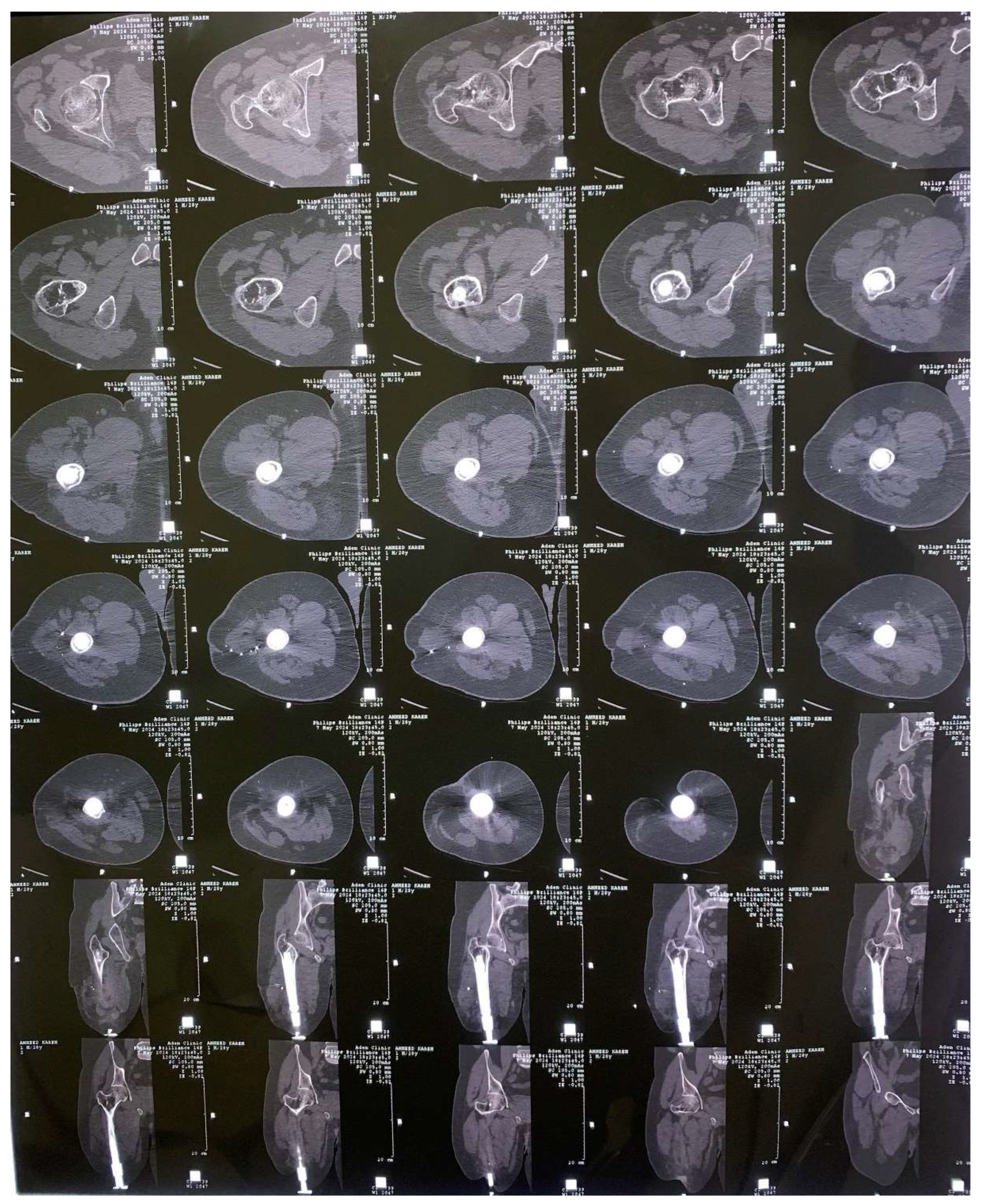
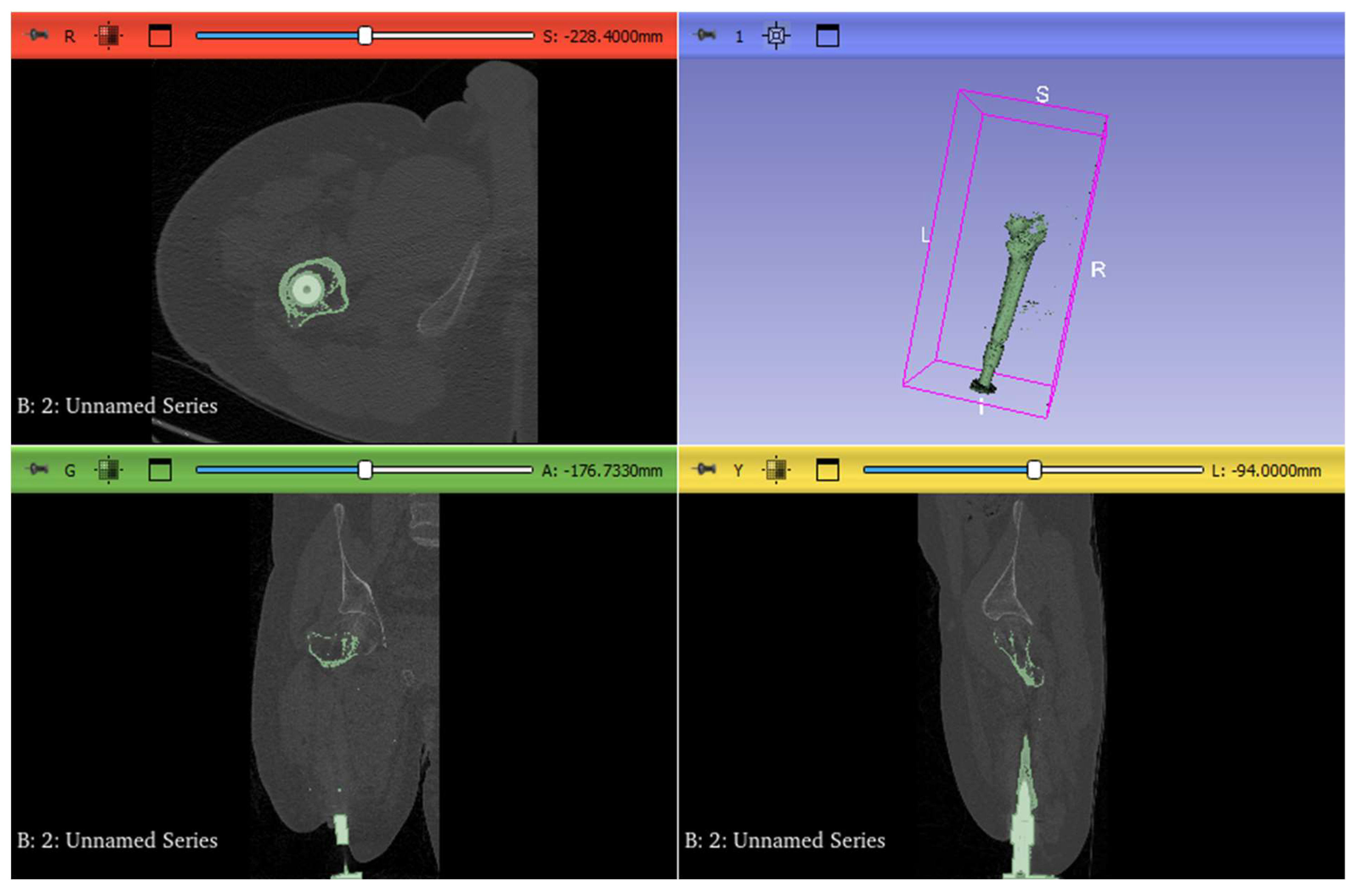
A CT scan was performed on the patient to capture detailed and accurate anatomical data of the bone region intended for the bone-anchored implant. This imaging technique provided high-resolution cross-sectional images in DICOM format, which contain precise spatial information about the bone’s shape, size, and density. These images are critical for creating an accurate 3D representation of the patient’s bone structure. The DICOM data was imported into 3D Slicer version 5.6.2, a powerful medical imaging software used for segmentation and reconstruction of anatomical models. Within 3D Slicer, the bone and implant areas were carefully segmented to generate a patient-specific 3D model of the bone-anchored implant. This model captures the exact dimensions and contours needed to simulate the implant’s mechanical behavior precisely. The finalized 3D model was then exported to ANSYS software for Finite Element Analysis (FEA), ensuring that the simulation results realistically reflect the implant’s interaction with the patient’s bone, as demonstrated in Figure 2. This approach enhances the precision of biomechanical evaluations and implant design.
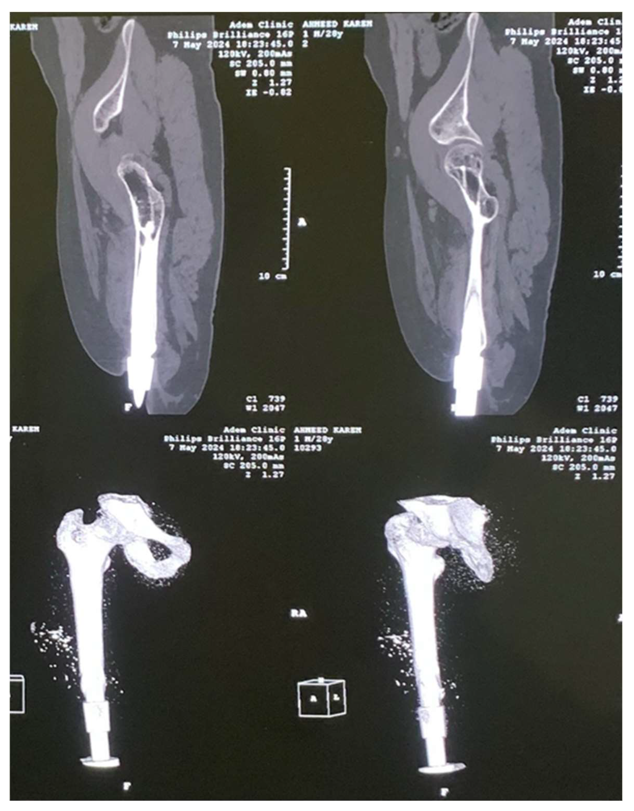
Figure 3 displays X-rays in projections and 3D reconstructions of a hip joint replacement with a femoral implant. The top images show the implant’s positioning within the femur, while the bottom color-enhanced 3D views illustrate variations in bone density variations and stress distribution. This type of imaging helps assess implant integration, load-bearing efficiency, and potential complications.
3D Slicer is an open-source and free software used for medical image analysis, particularly useful for evaluating patient CT scans. Figure 4 displays a 3D model in 3D Slicer, saved in STL format, which is then imported into SolidWorks.
Figure 5 illustrates the lower limb model using three uniaxial, infinitely rigid elements. The X–Y–Z axes represents the reference system of the force plate, while (X–Y–Z)B denotes the bone (femur) reference system. L indicates the tibia length, and D represents the distance from the knee to the implant position along the femur. Β and α correspond to the angles between the foot and tibia and between the tibia and femur, respectively.
Topology optimization is an advanced computational technique used to optimize the material layout within a given design space to achieve the best structural performance while minimizing weight and material usage. It systematically eliminates non-essential material, resulting in lightweight yet strong and efficient structures. In the context of bone-anchored implants for prosthetic limbs, topology optimization facilitates the identification of the optimal distribution of implant material to enhance stability, reduce stress concentrations, and improve load transfer. It can reduce the weight and size of the implant without compromising its structural integrity, thereby improving the comfort and functionality for users. Topology optimization can refine the geometry of the implant to minimize stress-shielding, which occurs when the implant takes too much load, leading to bone resorption. Additionally, it can help create designs that better mimic the mechanical properties of natural bone, reducing the risk of implant failure or loosening over time. By employing topology optimization, this study aims to develop bone-anchored implants that are not only biomechanically efficient but also lightweight and durable, improving the quality of life for individuals with limb amputations. The study utilizes topological optimization in ANSYS to design an implant that enhances bone ingrowth while maintaining implant–bone complex stiffness and implant body strength. By minimizing structural compliance, the optimization maximizes global stiffness, achieving volume reduction without compromising mechanical integrity. Osseointegrated implants with different lengths such as 207 mm, 217 mm, and 197 mm are investigated to indicate the optimum length.

3. Numerical Simulations

In this section, Computer-Aided Design (CAD) and FEM analysis methods and techniques were employed in model generating and simulating.

3.1. CAD Model

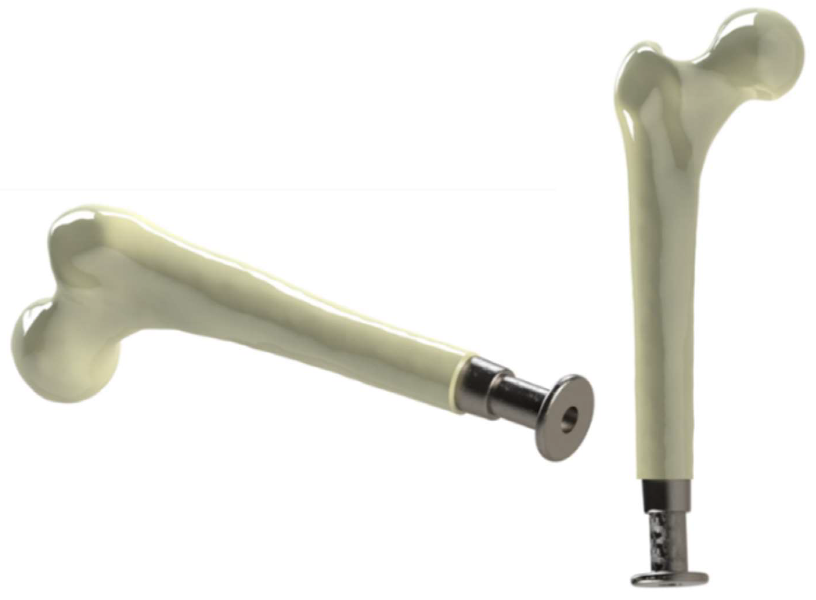
The Soildworks software 2023 was used to create the 3D model of the osseointegrated implant. Figure 6 explains the model of the osseointegrated implant used in this study. The dimensions of the osseointegrated implant are shown in Figure 7.

3.2. Material Selection

In this study, aluminum alloy, Ti-6Al-4V, and Ti-6Al-4V coated with platinum are used for the Osseointegration Prosthetic Limb (OPL) implant. Material properties are presented in Table 1 and Table 2 for both bone and implant. Platinum-coated implants have shown promising results in bone applications due to their excellent long-term biological safety and potential in anti-infection design [32]. Platinum is a chemically inert and biocompatible metal that resists corrosion and does not release harmful ions into surrounding tissues, minimizing immune responses and inflammation. This makes it suitable for long-term implantation in bone, where stable integration and minimal toxicity are critical [33,34]. For percutaneous implants, platinum coatings can reduce bacterial adhesion due to their smooth, non-reactive surface. In dental applications, where implants are exposed to the oral microbiome, nanocoatings and antibiotic slow-release technologies are valuable tools for infection control. Nanostructured surfaces, including platinum-based nanomaterials, can promote osseointegration while preventing bacterial attachment [35]. Additionally, antibiotic slow-release systems embedded in or applied to the implant surface provide sustained antimicrobial activity, especially in the early healing phase when the risk of infection is highest [36,37]. These strategies are essential for reducing implant-related infections and improving long-term success rates. Antibiotic-free antibacterial coatings are essential for orthopedic implants. Platinum-based alloys offer a promising solution due to their durability. Although sputter-coated platinum coatings showed limited antibacterial activity and low ion release, further optimization could enhance their clinical effectiveness [31].

3.3. Mesh Generation

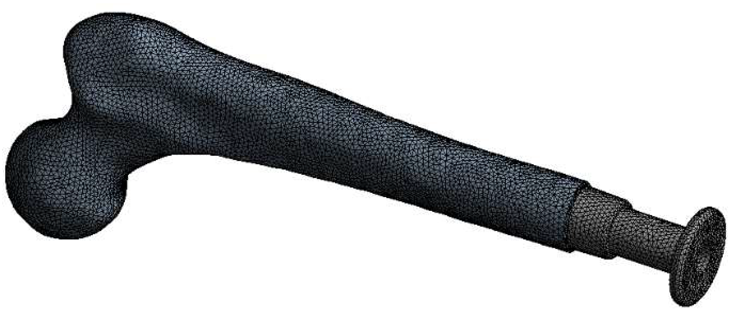
An unstructured mesh was selected for the simulation domain due to the complication of the model of the osseointegrated implant–bone model. The three-dimensional mesh structure is illustrated in Figure 8. To ensure mesh independence, a grid dependence was conducted by evaluating solutions at varying element sizes. Thus, for more accuracy and precision, the numerical research will employ a mesh model with 884,454 components. To pass the mesh dependency check, three grid systems with 152,455, 245,949, and 287,653 elements are created. Between the finest grid and the average number of grids, there is a less than 2.21% difference in the stress. Therefore, the 287,653-cell model was selected for this study. Additionally, local mesh refinement was applied at contact surfaces to enhance solution fidelity.

3.4. FEM Procedure

The model was drawn by CAD software (version 2022) after that the ANSYS software was employed for setting up the boundary conditions and analysis of the static structure. Firstly, the OPL osseointegrated implant for bones is created by SOLIDWORKS, then the file is imported to ANSYS geometry. Secondly, the material is created for the osseointegrated implant, then the mesh model is generated at a suitable element size. The finite element analysis focused on defining accurate boundary conditions for knee joint models. Each part was fixed according to its anatomical location, and forces from research were applied to compute von Mises stresses during gait. Loads were implemented in ANSYS Workbench. Moments in three directions are also applied. The fixed surface of the bones is determined, and results such as equivalent stress and equivalent elastic strain are extracted. Aluminum alloy, Ti-6Al-4V, and Ti-6Al-4V coated with platinum are used for the OPL osseointegrated implant. In the case of coated Ti-6Al-4V, the platinum coating has a thickness of 10 μm.

4. Results and Discussion

In this section, based on the numerical simulation of the implant, we present some results on the stress distribution in the implant interface that help us to optimize the implant geometry for subsequent use in other people.

4.1. Effects of Different Materials

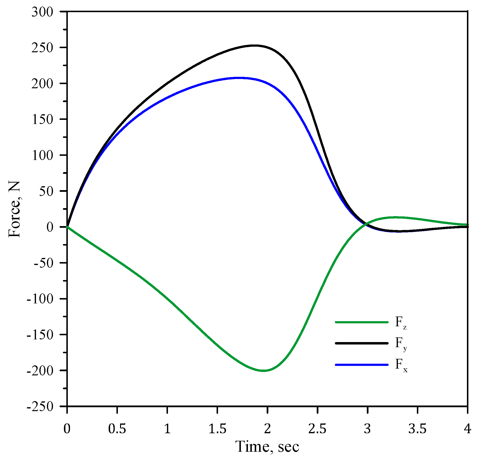
Applying force in three directions (x, y, and z) on an osseointegrated implant is critical to accurately simulate real-world loading conditions, as implants experience multi-directional forces during daily activities. Axial force (z-direction) represents the vertical load from body weight during standing or walking, primarily causing compressive or tensile stresses along the implant’s length. Lateral force (x-direction) mimics side-to-side movements or lateral impacts, essential for evaluating bending stress and lateral stability. Anterior–posterior force (y-direction) replicates forward and backward forces through walking or sudden movements, highlighting shear stress and stability in that direction. In FEA by means of ANSYS software, these directional forces are applied to the implant model to assess stress distribution, equivalent stress (von Mises stress), and deformation. Investigating the implant’s response to multi-directional forces helps identify stress concentration zones and potential failure points. This comprehensive evaluation aids in optimizing implant design, improving mechanical stability, and ensuring long-term durability for prosthetic applications. Figure 9 shows the applied force on the implant in three directions.
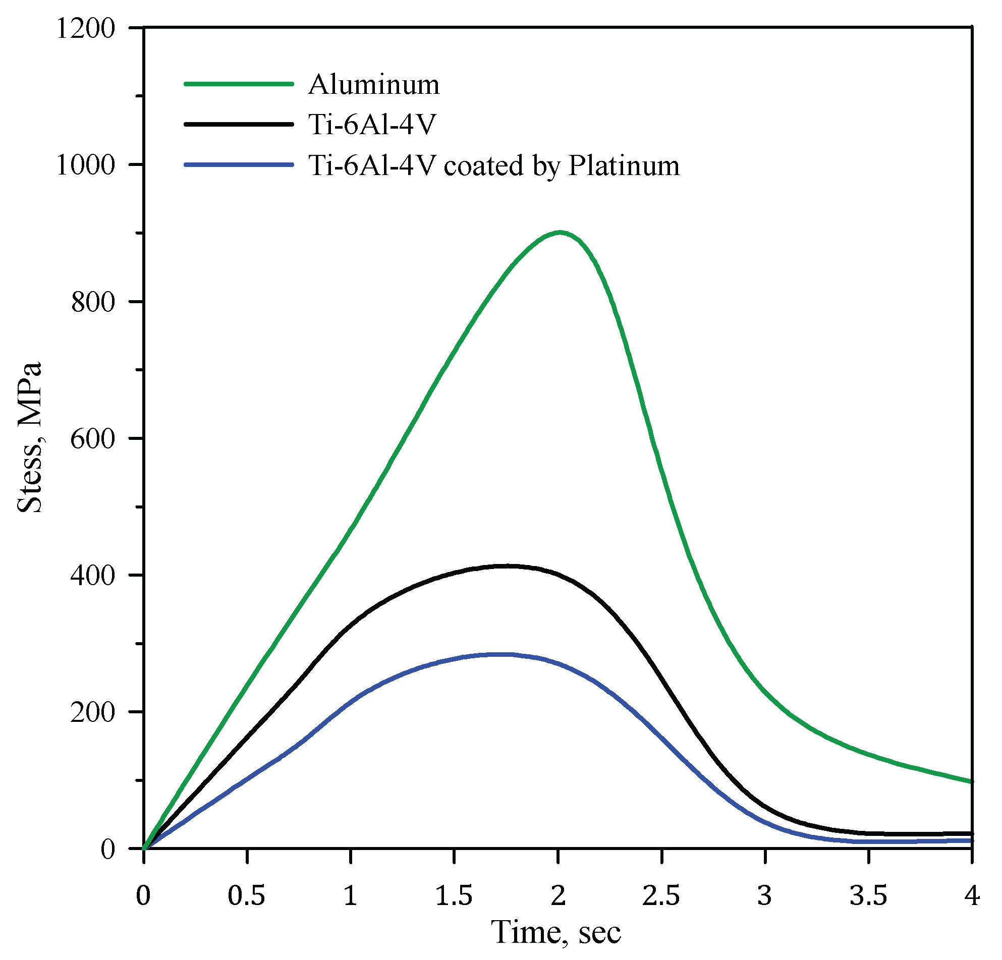
Figure 10 explains the equivalent von Mises stress for the assembly and knee bone with implants of aluminum, Ti-6Al-4V, and Ti-6Al-4V coated with 10 µm platinum. Among aluminum, Ti-6Al-4V, and Ti-6Al-4V coated with 10 µm platinum, aluminum exhibits the highest equivalent von Mises stress due to its low yield strength and elastic modulus, making it prone to deformation under load. Ti-6Al-4V, with a higher yield strength and modulus, distributes stress more effectively, reducing von Mises stress. Ti-6Al-4V with platinum coating slightly increases surface stress due to the modulus mismatch, but bulk stress remains similar to uncoated Ti-6Al-4V. Overall, aluminum experiences the highest stress, while Ti-6Al-4V minimizes stress concentration, ensuring better implant durability. Using Ti-6Al-4V and Ti-6Al-4V coated with 10 µm platinum reduce the stress by 46% and 65%, respectively. Ti-6Al-4V coated with a 10 µm platinum layer enhances implant performance by improving biocompatibility, corrosion resistance, and durability. The platinum coating promotes better osseointegration, reducing implant rejection risks. It also provides excellent wear resistance, extending implant lifespan. Additionally, platinum’s high conductivity minimizes stress-shielding effects, ensuring optimal load distribution and mechanical stability, making it ideal for bone-anchored prosthetic applications.
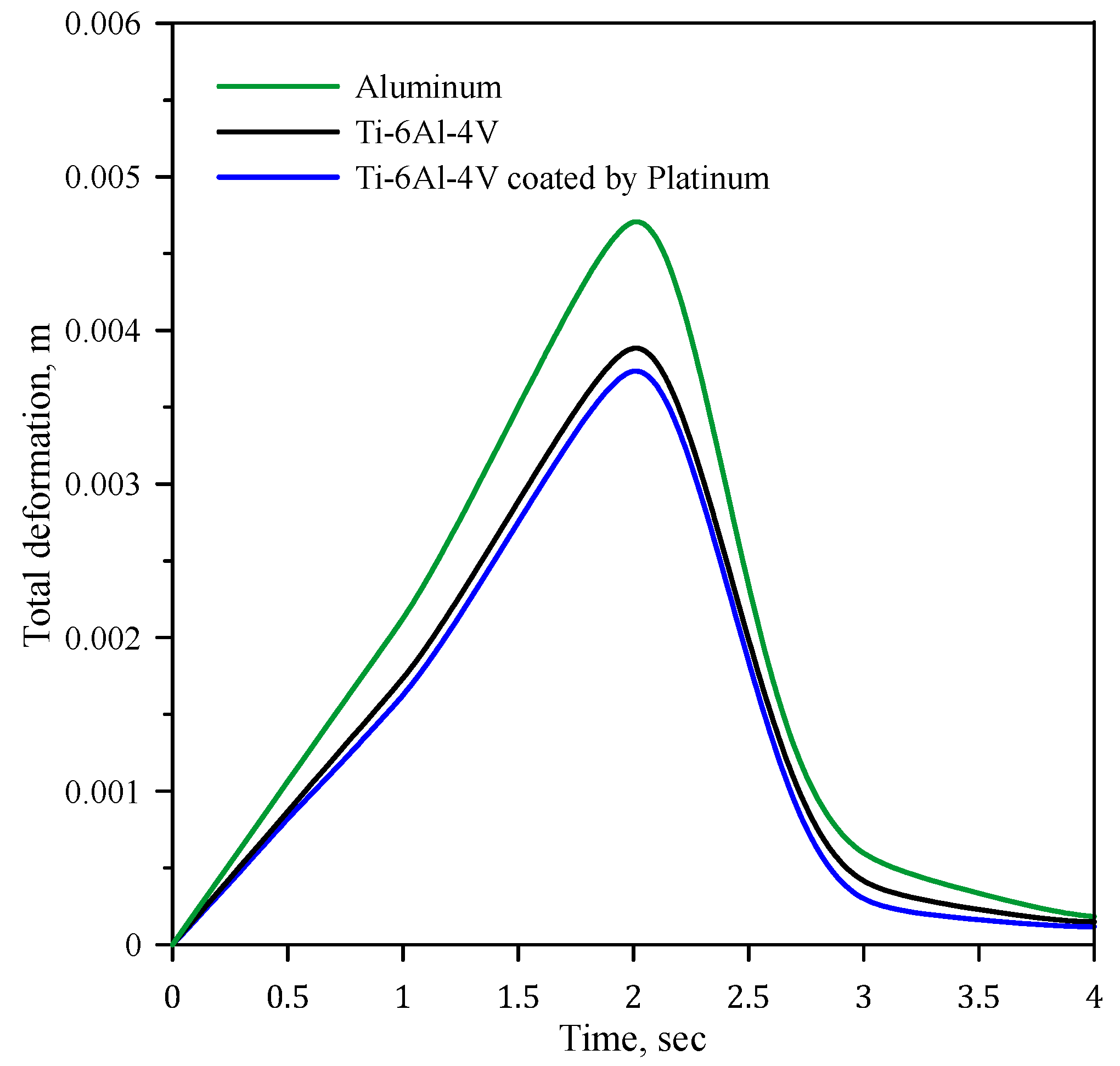
Figure 11 presents the maximum deformation for the knee bone–implant assembly using three materials: aluminum, Ti-6Al-4V, and Ti-6Al-4V coated with 10 µm platinum. In terms of total deformation, aluminum exhibits the highest deformation due to its lower elastic modulus and yield strength, resulting in greater flexibility and displacement under load. Ti-6Al-4V, with a higher modulus and yield strength, deforms significantly less than aluminum. Ti-6Al-4V coated with 10 µm platinum further reduces surface deformation, as the stiffer coating distributes stress more effectively. However, since the coating is thin, its impact on overall deformation is minimal. Thus, aluminum shows the highest total deformation, while Ti-6Al-4V and its coated version exhibit lower values, ensuring better implant stability. The aluminum, Ti-6Al-4V, and Ti-6Al-4V coated with 10 µm platinum achieve a total deformation of 0.0048 m, 0.0039, and 0.0037, respectively. Aluminum exhibits the highest deformation among the three materials. Ti-6Al-4V deforms 18.75% less than aluminum. Ti-6Al-4V coated with 10 µm platinum shows the least deformation, being 22.92% less than aluminum and 5.13% less than uncoated Ti-6Al-4V. Coating the Ti-6Al-4V with platinum improves the implant’s stiffness and reduces deformation compared to uncoated material.
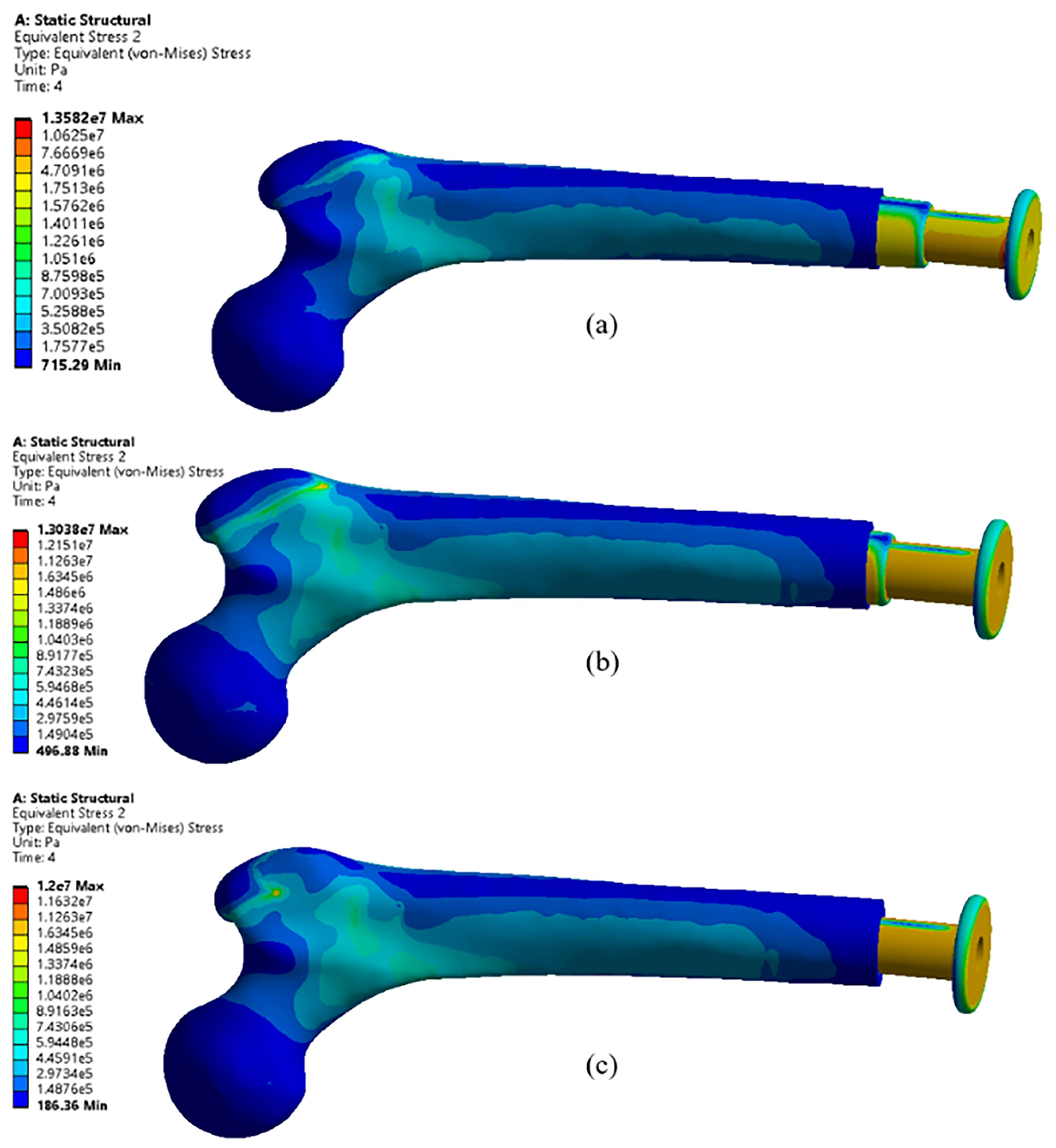
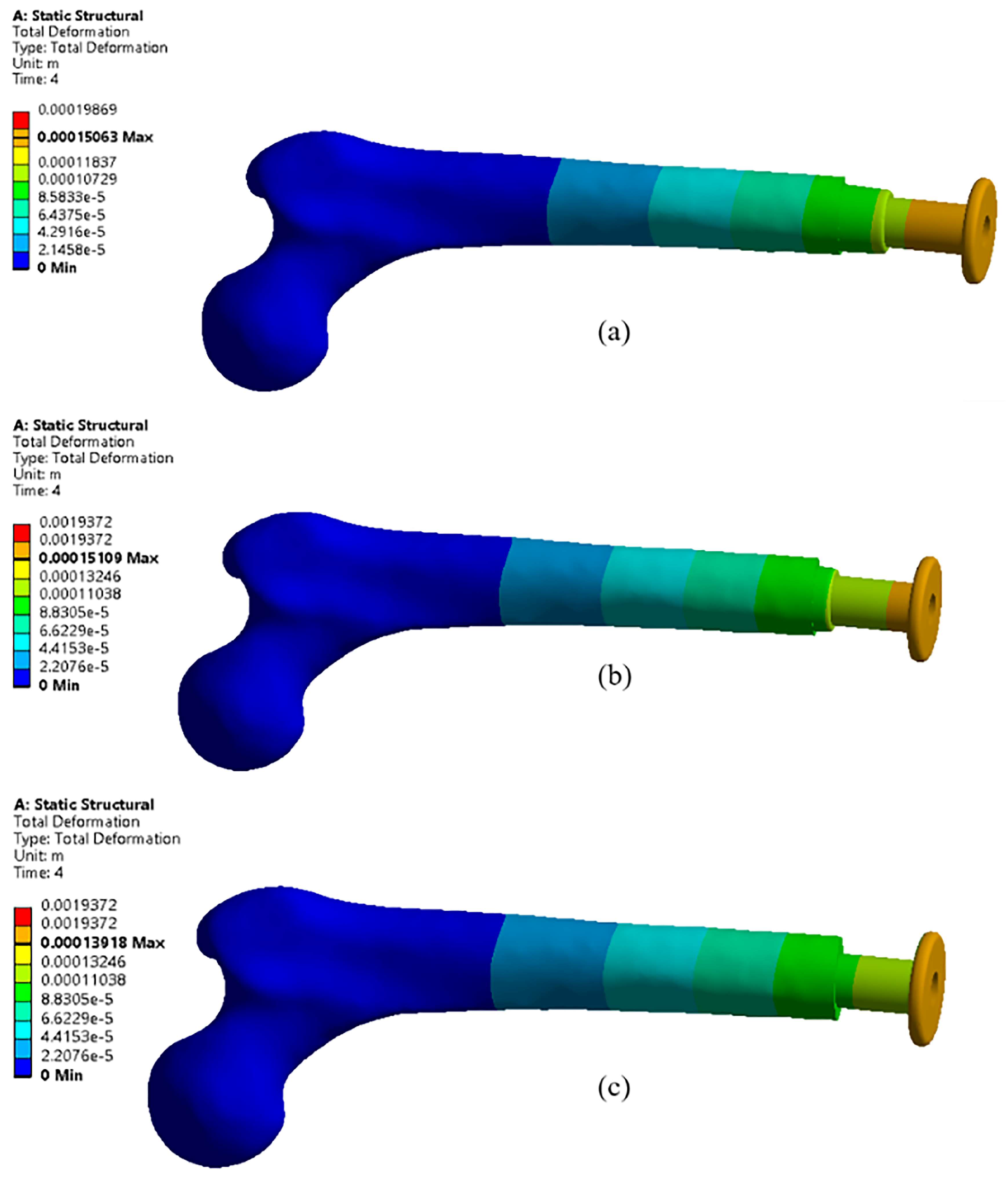
Figure 12 and Figure 13 display the equivalent stress distribution and total deformation in the osseointegrated implant–bone assembly for different implant materials, respectively. The stress patterns vary significantly depending on material stiffness and strength characteristics. In the case of the aluminum implant, the contours show higher stress concentrations near the bone–implant interface, indicating a greater degree of stress transfer to the surrounding bone due to its lower stiffness. In contrast, the Ti-6Al-4V implant exhibits more evenly distributed stress contours, signifying better stress absorption and load-bearing capacity. Furthermore, the Ti-6Al-4V coated with 10 µm platinum shows the most favorable stress distribution, with minimal stress concentration zones, indicating enhanced load transfer efficiency and reduced stress on the bone interface. This outcome can be attributed to the coating’s ability to improve mechanical compatibility and reduce stress peaks. Overall, the coated Ti-6Al-4V implant demonstrates superior performance in minimizing stress concentrations and promoting long-term stability.
Contours of total deformation for the osseointegrated implant assembly and knee bone with implants of aluminum, Ti-6Al-4V, and Ti-6Al-4V coated with 10 µm platinum are investigated in Figure 11. The deformation patterns differ significantly based on the material properties, particularly stiffness and elasticity. The aluminum implant shows the highest deformation among the three materials. Because of its lower stiffness, the applied loads result in more pronounced displacement, especially near the implant–bone interface. This indicates that aluminum may be less suitable for applications requiring high structural stability, as excessive deformation can compromise implant performance and longevity. In contrast, the Ti-6Al-4V implant exhibits noticeably lower total deformation compared to aluminum, reflecting its superior mechanical strength and higher elastic modulus. The stress is more efficiently distributed throughout the implant structure, leading to improved stability and reduced risk of mechanical failure. The Ti-6Al-4V implant coated with 10 µm platinum demonstrates the least deformation among the three cases. The coating improves the material’s stiffness, further minimalizing displacement and indicating improved load-bearing capacity. This reduced deformation helps maintain the implant’s alignment and structural integrity under operational conditions.

4.2. Effects of Different Lengths

Equivalent stress, often represented as von Mises stress, is a critical factor in evaluating the mechanical performance of osseointegrated implants, as it accounts for the combined effects of multi-axial stresses. In the context of bone-anchored prosthetic implants, equivalent stress is vital for assessing the implant’s structural integrity and ensuring that stress levels do not exceed the material’s yield strength, which could lead to failure. When analyzing osseointegrated implants with different lengths, the length significantly affects stress distribution and concentration. Equivalent stress for osseointegrated implants with different lengths such as 207 mm, 217 mm, and 197 mm is investigated in Figure 14. Shorter implants exhibit higher equivalent stress, primarily at the bone–implant interface, due to reduced contact area and increased stress concentration. This leads to localized bone resorption or implant loosening, compromising the long-term stability of the prosthesis. Longer implants distribute the applied loads over a larger surface area, reducing stress concentration at the interface. However, excessively long implants may introduce bending stress and increased strain in the distal regions, especially under lateral or torsional loads.
Figure 15 shows contours of total deformation for osseointegrated implants with different lengths, such as 217 mm, 207 mm, and 197 mm. As shown in this figure, the deformation decreases with the decrease in implant length. When the implant length is increased to 217 mm, the deformation contours indicate a noticeable increase in deformation. A longer implant length creates a larger moment arm, leading to greater bending moments when subjected to axial, lateral, or torsional loads. This increased bending moment causes higher deformation, particularly at the distal end, as the implant structure flexes more under the applied forces. Additionally, the longer implant has increased flexibility, which further contributes to the deformation under loading. Conversely, when the implant length decreases, as in the 197 mm implant, the deformation decreases. A shorter implant length reduces the lever arm effect, thereby decreasing the bending moments generated under load. This results in a more rigid structure with reduced deformation. Furthermore, a shorter implant has less material to deform, and the stress distribution is more localized near the bone–implant interface, maintaining the overall stability. The 207 mm implant length represents a balanced configuration, where the deformation is comparatively less due to the optimal combination of length and stiffness. The moderate length minimizes the bending effects while maintaining enough structural integrity to resist deformation. Thus, the decrease in implant length leads to reduced deformation due to the minimized bending effects and increased structural stiffness.

5. Conclusions

Bone-anchored implants represent a significant advancement in prosthetic technology, providing a stable and functional alternative to conventional socket-based prostheses. These systems improve stability, comfort, and natural limb movement through innovations in osseointegration, surgical methods, and implant materials. Despite these benefits, challenges remain, including infection risk, long-term stability, and the importance of careful patient selection and follow-up. Ongoing research is essential to improve safety and effectiveness, ensuring wider acceptance of these innovative solutions. In this study, ANSYS Workbench is used to analyze the static structure of the assembly of SW osseointegrated implant and bone. The osseointegrated implant with different materials like aluminum, Ti-6Al-4V, and Ti-6Al-4V coated with 10 µm platinum is investigated. Different lengths such as 207 mm, 217 mm, and 197 mm are studied. The mesh generations are verified with different element numbers, and boundary conditions are applied. The equivalent stress and total deformations are studied as crucial factors. The results can be concluded in the following points:
  • Using Ti-6Al-4V and Ti-6Al-4V coated with 10 µm platinum reduces the stress by 46% and 65%, respectively.
  • Ti-6Al-4V coated with 10 µm platinum achieves the minimum equivalent stress, indicating the importance of platinum coating.
  • The Ti-6Al-4V coated with a 10 µm layer of platinum exhibits the lowest deformation, measuring 22.92% less than aluminum and 5.13% less than the uncoated Ti-6Al-4V.
  • Shorter implant lengths result in reduced deformation due to minimized bending effects and increased stiffness, while longer implants, like the 217 mm length, exhibit higher deformation due to increased flexibility and a pronounced lever arm effect.

Author Contributions

Conceptualization, H.M. and J.S.C.; methodology, H.M. and M.S.; software, R.B.A.-T.; validation, R.B.A.-T. and H.M.; formal analysis, R.B.A.-T.; investigation, R.B.A.-T. and H.M.; resources, M.S.; data curation, R.B.A.-T.; writing—original draft preparation, R.B.A.-T.; writing—review and editing, H.M.; visualization, R.B.A.-T.; supervision, H.M. and M.S.; project administration, H.M.; All authors have read and agreed to the published version of the manuscript.

Funding

This research received no external funding.

Institutional Review Board Statement

The study was conducted in accordance with the Declaration of Helsinki, and approved by the Ethics Committee of Bu-Ali Sina University (protocol code of 7302 in the date of 26 August 2025).

Informed Consent Statement

Informed consent was obtained from all subjects involved in the study.

Data Availability Statement

The datasets used and/or analyzed during the current study are available from the corresponding author upon reasonable request due to ethical reasons.

Conflicts of Interest

The authors declare no conflicts of interest.

Abbreviations

The following abbreviations are used in this manuscript:
FEAFinite element analysis
CTComputed tomography
CADComputer-aided design
OPLOsseointegration prosthetic limb

References

  1. Robinson, D.L.; Safai, L.; Harandi, V.J.; Graf, M.; Lizama, L.E.C.; Lee, P.; Galea, M.P.; Khan, F.; Tse, K.M.; Ackland, D.C. Load response of an osseointegrated implant used in the treatment of unilateral transfemoral amputation: An early implant loosening case study. Clin. Biomech. 2020, 73, 201–212. [Google Scholar] [CrossRef]
  2. Gil, S.; Fernandez-Pineda, I.; Rao, B.; Neel, M.D.; Baker, J.N.; Wu, H.; Wu, J.; Anghelescu, D.L. Role of amputation in improving mobility, pain outcomes, and emotional and psychological well-being in children with metastatic osteosarcoma. Am. J. Hosp. Palliat. Med. 2019, 36, 105–110. [Google Scholar] [CrossRef] [PubMed]
  3. Valente, F.; Marrocco, A.; Falcinelli, C. Impact of physiological and non-physiological loading scenarios and crown material on periimplant bone stress distribution: A 3D finite element study. J. Mech. Behav. Biomed. Mater. 2025, 163, 106894. [Google Scholar] [CrossRef] [PubMed]
  4. Ogawa, T.; Hirota, M.; Shibata, R.; Matsuura, T.; Komatsu, K.; Saruta, J.; Att, W. The 3D theory of osseointegration: Material, topography, and time as interdependent determinants of bone–implant integration. Int. J. Implant Dent. 2025, 11, 49. [Google Scholar] [CrossRef]
  5. Taylor, T.D.; Agar, J.R. Twenty years of progress in implant prosthodontics. J. Prosthet. Dent. 2002, 88, 89–95. [Google Scholar] [CrossRef]
  6. Stenlund, P.; Trobos, M.; Lausmaa, J.; Branemark, R.; Thomsen, P.; Palmquist, A. Effect of load on the bone around bone-anchored amputation prostheses. J. Orthop. Res. 2017, 35, 1113–1122. [Google Scholar] [CrossRef]
  7. Koehler, S.R.; Dhaher, Y.Y.; Hansen, A.H. Cross-validation of a portable, six-degree-of-freedom load cell for use in lower-limb prosthetics research. J. Biomech. 2014, 47, 1542–1547. [Google Scholar] [CrossRef]
  8. Prochor, P.; Sajewicz, E. The Influence of Geometry of Implants for Direct Skeletal Attachment of Limb Prosthesis on Rehabilitation Program and Stress-Shielding Intensity. BioMed Res. Int. 2019, 2019, 6067952. [Google Scholar] [CrossRef]
  9. Al-Maliky, F.T.; Chiad, J.S. Study and evaluation of four bar polycentric knee used in the prosthetic limb for transfemoral amputee during the gait cycle. Mater. Today Proc. 2021, 42, 2706–2712. [Google Scholar] [CrossRef]
  10. Frossard, L.; Laux, S.; Geada, M.; Heym, P.P.; Lechler, K. Load applied on osseointegrated implant by transfemoral bone-anchored prostheses fitted with state-of-the-art prosthetic components. Clin. Biomech. 2021, 89, 105457. [Google Scholar] [CrossRef]
  11. Guo, T.; Gulati, K.; Arora, H.; Han, P.; Fournier, B.; Ivanovski, S. Orchestrating soft tissue integration at the transmucosal region of titanium implants. Acta Biomater. 2021, 124, 33–49. [Google Scholar] [CrossRef] [PubMed]
  12. Heimke, G.; Leyen, S.; Willmann, G. Knee arthoplasty: Recently developed ceramics offer new solutions. Biomaterials 2002, 23, 1539–1551. [Google Scholar] [CrossRef] [PubMed]
  13. Viceconti, M.; Ricci, S.; Pancanti, A.; Cappello, A. Numerical model to predict the long-term mechanical stability of cementless orthopaedic implants. Med. Biol. Eng. Comput. 2004, 42, 747–753. [Google Scholar] [CrossRef] [PubMed]
  14. Helgason, B.; Palsson, H.; Runarsson, T.P.; Frossard, L.; Viceconti, M. Risk of failure during gait for direct skeletal attachment of a femoral prosthesis: A finite element study. Med. Eng. Phys. 2009, 31, 595–600. [Google Scholar] [CrossRef]
  15. Tillander, J.; Hagberg, K.; Hagberg, L.; Branemark, R. Osseointegrated titanium implants for limb prostheses attachments: Infectious complications. Clin. Orthop. Relat. Res. 2010, 468, 2781–2788. [Google Scholar] [CrossRef]
  16. Branemark, R.; Emanuelsson, L.; Palmquist, A.; Thomsen, P. Bone response to laser-induced micro- and nano-size titanium surface features. Nanomedicine 2011, 7, 220–227. [Google Scholar] [CrossRef]
  17. Tomaszewski, P.K.; Verdonschot, N.; Bulstra, S.K.; Rietman, J.S.; Verkerke, G.J. Simulated bone remodeling around two types of osseointegrated implants for direct fixation of upper-leg prostheses. J. Mech. Behav. Biomed. Mater. 2012, 15, 167–175. [Google Scholar] [CrossRef]
  18. Frossard, L.; Langton, C.; Perevoshchikova, N.; Feih, S.; Powrie, R.; Barrett, R.; Lloyd, D. Next-generation devices to diagnose residuum health of individuals suffering from limb loss: A narrative review of trends, opportunities, and challenges. J. Sci. Med. Sport 2023, 26 (Suppl. 1), S22–S29. [Google Scholar] [CrossRef]
  19. Pitkin, M. Design features of implants for direct skeletal attachment of limb prostheses. J. Biomed. Mater. Res. A 2013, 101, 3339–3348. [Google Scholar] [CrossRef]
  20. Tsikandylakis, G.; Berlin, O.; Branemark, R. Implant survival, adverse events, and bone remodeling of osseointegrated percutaneous implants for transhumeral amputees. Clin. Orthop. Relat. Res. 2014, 472, 2947–2956. [Google Scholar] [CrossRef]
  21. van Eck, C.F.; McGough, R.L. Clinical outcome of osseointegrated prostheses for lower extremity amputations. Curr. Orthop. Pract. 2015, 26, 349–357. [Google Scholar] [CrossRef]
  22. Muderis, M.A.; Aschoff, H.H.; Bosley, B.; Raz, G.; Gerdesmeyer, L.; Burkett, B. Direct skeletal attachment prosthesis for the amputee athlete: The unknown potential. Sports Eng. 2016, 19, 141–145. [Google Scholar] [CrossRef]
  23. Li, Y.; Lindeque, B. Percutaneous Osseointegrated Prostheses for Transfemoral Amputations. Orthopedics 2018, 41, 75–80. [Google Scholar] [CrossRef] [PubMed]
  24. Prochor, P.; Sajewicz, E. A Comparative Analysis of Standardised Threads for Use in Implants for Direct Skeletal Attachment of Limb Prosthesis: A Finite Element Analysis. Appl. Bionics Biomech. 2019, 2019, 8027064. [Google Scholar] [CrossRef] [PubMed]
  25. Branemark, R.P.; Hagberg, K.; Kulbacka-Ortiz, K.; Berlin, O.; Rydevik, B. Osseointegrated Percutaneous Prosthetic System for the Treatment of Patients with Transfemoral Amputation: A Prospective Five-year Follow-up of Patient-reported Outcomes and Complications. J. Am. Acad. Orthop. Surg. 2019, 27, e743–e751. [Google Scholar] [CrossRef] [PubMed]
  26. Wang, W.; Lynch, J.P. Quantitative assessment of compress-type osseointegrated prosthetic implants in human bone using electromechanical impedance spectroscopic methods. Biomed. Eng. Lett. 2020, 10, 129–147. [Google Scholar] [CrossRef]
  27. Prochor, P.; Frossard, L.; Sajewicz, E. Effect of the material’s stiffness on stress-shielding in osseointegrated implants for bone-anchored prostheses: A numerical analysis and initial benchmark data. Acta Bioeng. Biomech. 2020, 22, 69–81. [Google Scholar] [CrossRef]
  28. Thesleff, A.; Ortiz-Catalan, M.; Branemark, R. The effect of cortical thickness and thread profile dimensions on stress and strain in bone-anchored implants for amputation prostheses. J. Mech. Behav. Biomed. Mater. 2022, 129, 105148. [Google Scholar] [CrossRef]
  29. Hagberg, K.; Ghasemi Jahani, S.A.; Omar, O.; Thomsen, P. Osseointegrated prostheses for the rehabilitation of patients with transfemoral amputations: A prospective ten-year cohort study of patient-reported outcomes and complications. J. Orthop. Transl. 2023, 38, 56–64. [Google Scholar] [CrossRef]
  30. Zhang, G.; Li, J.; Li, J.; Zhou, X.; Xie, J.; Wang, A. Selective Laser Melting Molding of Individualized Femur Implant: Design, Process, Optimization. J. Bionic Eng. 2021, 18, 128–137. [Google Scholar] [CrossRef]
  31. van Hoogstraten, S.W.G.; van Agtmaal, J.L.; Samijo, S.K.; Peeters, L.C.W.; van Maris, M.P.F.H.L.; Arts, J.J.C. Antimicrobial and biocompatibility assessment of platinum-based metal alloy coatings for total joint arthroplasty. Surf. Coat. Technol. 2025, 511, 132281. [Google Scholar] [CrossRef]
  32. Faadhila, A.; Taufiqurrakhman, M.; Katili, P.A.; Rahman, S.F.; Lestari, D.C.; Whulanza, Y. Optimizing PEEK implant surfaces for improved stability and biocompatibility through sandblasting and the platinum coating approach. Front. Mech. Eng. 2024, 10, 1360743. [Google Scholar] [CrossRef]
  33. Jayasree, A.; Cartmell, S.; Ivanovski, S.; Gulati, K. Electrically stimulated dental implants triggers soft-tissue integration and bactericidal functions. Adv. Funct. Mater. 2024, 34, 2311027. [Google Scholar] [CrossRef]
  34. Wu, W.; Chen, Z.; Li, B.; Cong, X.; Chen, Q. Mechanical and electrochemical properties of platinum coating by double glow plasma on titanium alloy substrate. Russ. J. Electrochem. 2013, 49, 76–80. [Google Scholar] [CrossRef]
  35. Akobundu, U.U.; Ifijen, I.H.; Duru, P.; Igboanugo, J.C.; Ekanem, I.; Fagbolade, M.; Ajayi, A.S.; George, M.; Atoe, B.; Matthews, J.T. Exploring the role of strontium-based nanoparticles in modulating bone regeneration and antimicrobial resistance: A public health perspective. RSC Adv. 2025, 15, 10902–10957. [Google Scholar] [CrossRef]
  36. Alshimaysawee, S.; Fadhel Obaid, R.; Al-Gazally, M.E.; Alexis Ramírez-Coronel, A.; Bathaei, M.S. Recent advancements in metallic drug-eluting implants. Pharmaceutics 2023, 15, 223. [Google Scholar] [CrossRef]
  37. Woodward, B.K. 6—Platinum group metals (PGMs) for permanent implantable electronic devices. In Precious Metals for Biomedical Applications; Baltzer, N., Copponnex, T., Eds.; Woodhead Publishing: Sawston, UK, 2014; pp. 130–147. [Google Scholar]
  38. Mirulla, A.I.; Di Paolo, S.; Di Simone, F.; Ingrassia, T.; Nigrelli, V.; Zaffagnini, S.; Bragonzoni, L. Biomechanical analysis of two types of osseointegrated transfemoral prosthesis. Appl. Sci. 2020, 10, 8263. [Google Scholar] [CrossRef]
Figure 1. Instrumentation setup of the placement of the force plate for ground reaction force analysis.
Applmech 06 00077 g001
Figure 2. Pre-operative Computed Tomography (CT) scan of the patient.
Applmech 06 00077 g002
Figure 3. Computed tomography scan with 3D reconstruction showing a hip joint replacement.
Applmech 06 00077 g003
Figure 4. 3D reconstructed anatomical model generated using 3D Slicer software.
Applmech 06 00077 g004
Figure 5. Three-dimensional distribution of contact loads at the implant–bone interface.
Applmech 06 00077 g005
Figure 6. CAD model of assembly of bone and osseointegrated implants.
Applmech 06 00077 g006
Figure 7. Dimensions of the osseointegrated implant.
Applmech 06 00077 g007
Figure 8. Mesh generation for the assembly of bone and osseointegrated implant.
Applmech 06 00077 g008
Figure 9. Force distribution along three applied axes of fabricated osseointegrated implant.
Applmech 06 00077 g009
Figure 10. Comparison of maximum von Mises stress distribution across three implant materials.
Applmech 06 00077 g010
Figure 11. Maximum deformation of assembly and knee bone with implants of aluminum, Ti-6Al-4V, and Ti-6Al-4V coated with 10 µm platinum.
Applmech 06 00077 g011
Figure 12. Equivalent stress for osseointegrated implant with different materials: (a) aluminum, (b) Ti-6Al-4V, and (c) Ti-6Al-4V coated with 10 µm platinum.
Applmech 06 00077 g012
Figure 13. Total deformation for osseointegrated implant with different materials: (a) aluminum, (b) Ti-6Al-4V, and (c) Ti-6Al-4V coated with 10 µm platinum.
Applmech 06 00077 g013
Figure 14. Equivalent stress for osseointegrated implant with different lengths: (a) 207 mm, (b) 217 mm, and (c) 197 mm.
Applmech 06 00077 g014
Figure 15. Total deformation for osseointegrated implant with different lengths: (a) 207 mm, (b) 217 mm, and (c) 197 mm.
Applmech 06 00077 g015
Table 1. Properties of used material in this study [38].
PropertySymbolAlTi-6Al-4VPlatinum
Density [kg/m3]ρ2770443021,100
Young’s Modulus [GPa]E71115172
Poisson’s Ratio [-]υ0.330.220.38
Bulk Modulus [GPa]B69.6114.3233
Shear Modulus [GPa] G26.735.368
Tensile yield strength [MPa]σy2809393
Comprehensive Yield Strength [MPa]σc2809382
Tensile ultimate strength [MPa]σu31010701250
Table 2. Mechanical properties of the bone [38].
PropertySymbolValue
Density [kg/m3]ρ1900
Young’s Modulus [GPa]E6
Poisson’s Ratio [-]υ0.49
Bulk Modulus [GPa]B100
Shear Modulus [GPa]G2.013
Tensile yield strength [MPa]σy135
Comprehensive Yield Strength [MPa]σc130
Tensile ultimate strength [MPa]σu130
Disclaimer/Publisher’s Note: The statements, opinions and data contained in all publications are solely those of the individual author(s) and contributor(s) and not of MDPI and/or the editor(s). MDPI and/or the editor(s) disclaim responsibility for any injury to people or property resulting from any ideas, methods, instructions or products referred to in the content.