Article

Modeling Kinematic and Dynamic Structures with Hypergraph-Based Formalism

1
Department of Informatics, Széchenyi István University, H-9026 Győr, Hungary
2
Department of Vehicle Production and Engineering, Széchenyi István University, H-9026 Győr, Hungary
*
Authors to whom correspondence should be addressed.
Appl. Mech. 2025, 6(4), 74; https://doi.org/10.3390/applmech6040074
Submission received: 29 July 2025 / Revised: 23 September 2025 / Accepted: 7 October 2025 / Published: 9 October 2025

Abstract

This paper introduces a hypergraph-based formalism for modeling kinematic and dynamic structures in robotics, addressing limitations of the existing formats such as Unified Robot Description Format (URDF), MuJoCo-XML, and Simulation Description Format (SDF). Our method represents mechanical constraints and connections as hyperedges, enabling the native description of multi-joint closures, tendon-driven actuation, and multi-physics coupling. We present a tensor-based representation derived via star-expansion, implemented in the Hypergraph Model Cognition Framework (HyMeKo) language. Comparative experiments show a substantial reduction in model verbosity compared to URDF while retaining expressiveness for large-language model integration. The approach is demonstrated on simple robotic arms and a quarter vehicle model, with derived state-space equations. This work suggests that hypergraph-based models can provide a modular, compact, and semantically rich alternative for the next-generation simulation and design workflows. The introduced formalism reaches 50% reduction compared to URDF descriptions and 20% reduction compared to MuJoCo-XML descriptions.

1. Introduction

Modeling complex mechanical and robotic systems requires formal representations that can faithfully capture topology, constraints, and dynamic interactions among subsystems. Traditional description formats such as the Unified Robot Description Format (URDF) [1], Simulation Description Format (SDF) [2] and the MuJoCo XML [3] models are widely adopted in the robotics and simulation communities. However, these formats are fundamentally graph-based and primarily describe pairwise connections, making them well-suited for tree-structured kinematic chains, but less expressive for systems with closed loops, shared components, or higher-order constraints.
As robotic systems become increasingly complex—including tendon-driven actuation, parallel mechanisms, multiphysics coupling, and modular subsystems—the limitations of pairwise graph representations become more apparent. Hypergraphs [4,5], as a generalization of graphs that allow edges (hyperedges) to connect multiple nodes simultaneously, offer a natural way to describe higher-order interactions and many-to-many (N-ary) relationships. This formalism can concisely encode multijoint closures, shared actuation groups, and complex constraint networks without the verbosity or redundancy typical of current widespread (XML-based [6] or JSON-based [7]) formats [8].
Recent research has also explored the use of hypergraphs in mathematical modeling beyond simple connectivity, leveraging their structure in areas such as spectral analysis, machine learning, and geometric mechanics. Spectral analysis focuses on exploiting the spectral properties of hypergraphs [9] by analyzing their matrix and hypermatrix representations [10,11]. In machine learning, the extension of graph neural networks [12] to hypergraphs [13] is used to infer n-ary relationships. In geometric modeling of mechanical systems, the Dirac structures approach [14,15] and the port-Hamiltonian [16] systems gained prevalence. Dirac structures are the generalization of both symplectic and Poisson structures, by formalizing power-conversing interconnections, to formulate the Hamiltonian of interconnected and constrained mechanical systems. Port-Hamiltonian systems extend Dirac structures with port variables (i.e., similarly to an electric circuit) to capture basic interconnection laws together with power-conserving elements by a geometric structure, to define the Hamiltonian, thus describing the total energy stored in the system [17]. In particular, hypergraphs can possibly extend Dirac structures and port-Hamiltonian systems to hypergraph domains, enabling energy-consistent modeling of interconnected systems with higher-order coupling. Such formulations support modularity, reusability, and compatibility with data-driven approaches.
This paper introduces a hypergraph-based formalism for modeling kinematic and dynamic structures, implemented in a custom markup language called the Hypergraph Model Cognition Framework (HyMeKo) a previous work of the authors [18]. The markup language provides the description of directed hypergraphs (see Section 3.1) with separate vertex groups that describe data entries (similarly to JSON). The markup language incorporates a separate group of hyperedges to establish directed relationships between data entries with directionality and assign vector-valued weights through hyperarcs (described in Section 4). The proposed approach to describe kinematic structures with the markup language enables more compact, semantically rich, and modular descriptions compared to URDF or SDF, while remaining human-readable and amenable to automated generation by large language models. To validate the approach, we present several examples, including simple robotic arms, a robot similar to a selective compliance assembly robot arm (SCARA) [19] that is typically used as a reference model in many applications [20]. The other example is a quarter-vehicle suspension model. The quarter-vehicle example further demonstrates the ability to derive state-space equations from the hypergraph description and automatically generate a Simulink simulation model, showcasing the practical potential for dynamic systems modeling and simulation workflows.

2. Key Contributions of the Paper

This paper introduces a novel description methodology for modeling kinematic structures. The methodology is based on the fundamentals of directed hypergraphs, allowing the description of many-to-many and directed relationships in a structured format using the HyMeKo markup language. The proposed description language is a markup language capable of expressing arbitrary relational information, including physical structures. It is parsed with an LALR(1) parser, enabling efficient processing. Our research also shows a direct mapping between the HyMeKo-based description and the widespread kinematic description using transformation methods. In our experiments, the HyMeKo format is at least 20% more compact than common robot description formats (URDF and MuJoCo XML), but in the case of URDF, a reduction of around 50% was achieved. The transformation was concluded using Large-Language Models (LLMs), and the results statistically confirmed the compactness of the new format. The HyMeKo description naturally represents kinematic trees and kinematic graphs and further extends to more complex physical structures (e.g., a quarter-vehicle model and crane-like structures).
We demonstrate the approach in a one-joint linkage and a two-joint SCARA-like robot. Both kinematic structures are mapped to an equivalent URDF and MuJoCo-XML, both compatible for further simulation. We also used an LLM-based workflow to test the interpretability of the format. Moreover, we outline a direct and systematic translation from hypergraph-based form to URDF/SDF using formalized plugins and refined LLM generation process. The modularity and extensibility of the framework and methodology extend the use to robotics, physics modeling, and systems engineering applications.

3. Related Work

3.1. Hypergraphs

Hypergraphs are generalizations of graphs that allow edges to connect more than two vertices simultaneously. The article follows the convention defined in the fundamental book by Bretto [4]. An H ( V , E ) hypergraph is a mathematical structure with two sets:
  • V (hyper)vertices, similarly to simple graphs.
  • E hyperedges that can simultaneously connect multiple vertices (i.e., indicate relationships similar to sets), thus E : = { e ( v 1 , v 2 , v n ) | v 1 , v 2 v n V } .
A hypergraph can be treated as multi-sets, each element containing multiple elements. An example of a hypergraph is depicted in Figure 1, clearly depicting the set-based approach to hypergraphs, each hypervertex is related to multiple hyperedges simultaneously.
The generalization of directed graphs in the hypergraph domain is called directed hypergraphs (dirhypergraphs), providing directionality definitions for hyperedges through hyperarcs. A directed hypergraph is formally defined as H in Equation (1) (derived from [4]) as the disjoint set of vertices V and directed hyperedges E .
H = V ; E = { i : i I }
In the case of directed hypergraphs, the connections between hypervertices and hyperedges are attributed with directionality: indicating the direction of how the hypervertex is related to the hyperedge. The relation of a hypervertex to a hyperedge is described by hyperarcs a e , part of the e E , through the notion of tail and head of an arc. The hyperedge is partitioned accordingly to the set of vertices in the vertices in the tail set e connecting the vertices with the hyperarc tails ( e , i ) , and the set of vertices in the head set e + ( i , e + ) for each finite index set e E and I = i { 1 , 2 , , | V | } . Hyperarcs are attributed with the following properties, with a finite index set I:
  • A tail of the a hyperarc denotes the source element (a hyperedge or a hypervertex).
  • A head of the a hyperarc denotes the target element (a hyperedge or a hypervertex).
Thus, each hyperarc is an ordered set of pairs (following the definition in [4]) defined in Equation (2), indicating the target vertex target (with an appropriate index) and the edge, providing the definition of a hyperedge as a set of hyperarcs.
e i = e i + = ( e i + , i ) ; e i = ( i , e i )
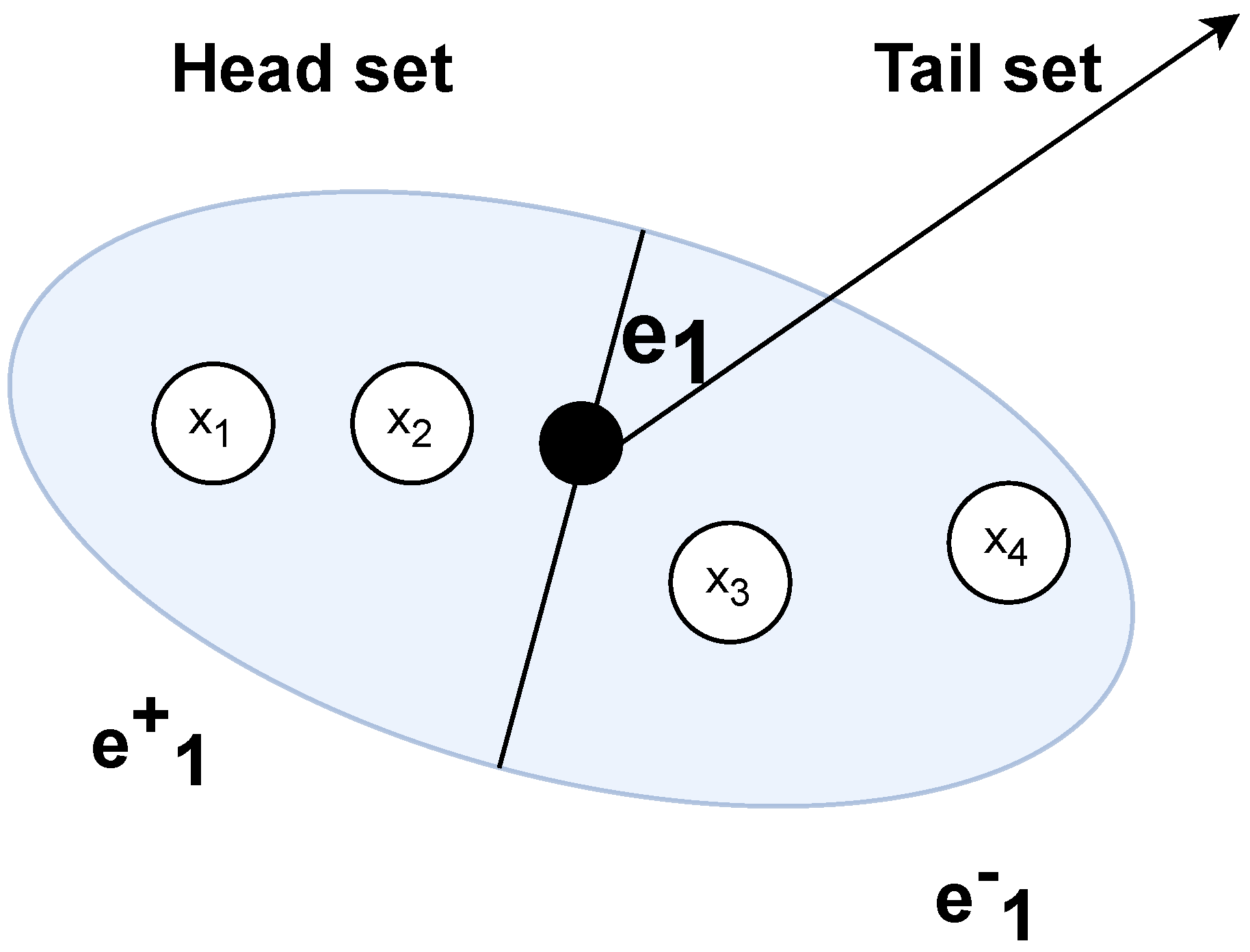
A dirhypergraph is best presented with an incidence graph denoting the directionality of set relationships (also called 2-factor decomposition). A minimal example of a hyperedge is shown in Figure 2. In the 2-factor decomposition view of the dirhypergraph, a new bipartite graph G ^ is constructed from the original hypergraph H ( V , E ) (as defined in Equation (1)) to capture and represent the essence of hyperarcs. In G ^ ( V * , E * ) , the disjunct set of V vertices and E edges is constructed as follows:
  • V * is composed of the union of V E , with two separate sets corresponding to the set of hypervertices V and hyperedges E , with the bipartite sets V , E .
  • E * is composed of the edges equivalent to hyperarcs, connecting V and E , with directionality equivalent to the direction of the head of the tail.
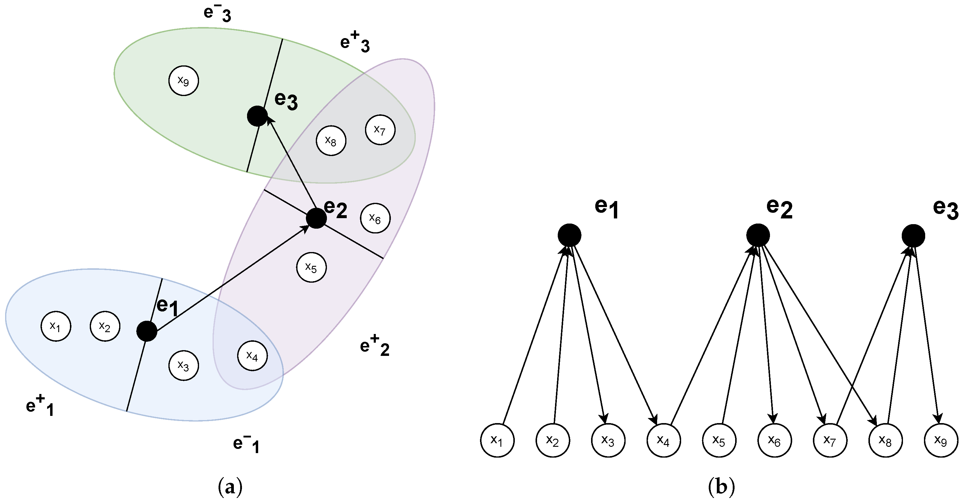
A more complex example dirhypergraph is shown in Figure 3 as H 1 ( V 1 , E 1 ) . This dirhypergraph has three hyperedges E 1 = { e 1 , e 2 , e 3 } and nine hypervertices V = { v 1 , v 2 , , v 9 } . Each hyperedge has a disjunct tail  e i and head  e i + set of arcs, defining the directionality of the hyperedge (in fact, a hypervertex can be connected simultaneously by multiple hyperedges).
Hypergraphs are typically decomposed to simple graphs using numerous methods, such as star-expansion [21], clique expansion and line expansion [5] in order to enable conventional processing and representation and interoperability with simple graphs (e.g., in knowledge representation applications). On the other hand, hypergraphs have seen recent prominence in neural network applications [22], utilizing hypergraph connections in graph neural networks [23] and even in transformer networks [24] to infer graph-like structures.

3.2. Limitations of URDF, SDF, and MuJoCo Formats

One domain where hypergraphs show particular promise is in the representation of robotic and mechanical system models, where currently adopted formats, such as Unified Robot Description Format (URDF) [25], Simulation Description Format (SDF), and MuJoCo XML [3] are largely graph-based and assume tree-structured kinematic chains or pairwise constraints. URDF is a very widely used format in addition to plain simulation which is predominantly used in Gazebo [26], also used in digital twin solutions [27]. However, URDF is limited in its ability to describe closed-loop mechanisms or shared components across multiple kinematic branches. Although SDF extends URDF with more flexible constraints and simulation-related metadata, it still follows a primarily pairwise structure, which is sometimes difficult to comprehend for complex robotics projects [25]. Adding elements, such as XACRO provides the ability to generate XML macros, but makes the debugging process more difficult [28]. MuJoCo allows for more complex connectivity but maintains a rigid structural interpretation with limitations on nonhierarchical or multiconstraint linkages. Furthermore, MuJoCo XML induces a hierarchical nested structure, making the description of complex crane-like structures difficult.
In contrast, a hypergraph-based formalism provides a compact and semantically expressive alternative, capable of natively representing high-order interactions such as multijoint closures, shared actuation groups, tendon-driven structures, and multiphysics coupling [8]. Each hyperedge may encode not only the topology of interconnection, but also associated constraints, energy transfer, or co-regulation mechanisms among subsystems. This makes hypergraph modeling well suited for next-generation simulation engines and formal mechanical system specifications where modularity and reusability are essential.

3.3. Hypergraph-Based Modeling of Physical Structures

Hypergraphs generalize traditional graphs by allowing hyperedges to connect more than two nodes. In addition to mechanical applications, hypergraph-based modeling received attention in semantic network analysis and prediction [29]. This structure makes them suitable for capturing higher-order interactions in complex systems, such as group-based communication in multi-agent systems, multi-component constraints in mechanical structures, and collective behaviors in biological networks. Unlike conventional graphs that encode pairwise interactions, hypergraphs naturally represent collective coupling among multiple subsystems. The use of hypergraphs in mathematical modeling has gained attention because of their ability to encode both topology and semantics of interactions more faithfully. In computational mechanics and control, hypergraphs enable a compact and modular representation of systems where elements are shared among more than two components, such as tendon-actuated limbs or circuit junctions with multiple terminals. This representation provides a natural foundation for extending geometric modeling frameworks like Dirac structures and port-Hamiltonian systems.
The application of hypergraphs and Dirac structures to the modeling of complex dynamical systems has emerged as a promising synthesis of geometric mechanics and network theory. Classical Dirac structures, originally defined on the Courant algebroid T M T * M , generalize both symplectic and Poisson structures and have been widely used in the study of port-Hamiltonian systems [14]. These systems emphasize power-conserving interconnections and modular compositions, where Dirac structures represent the topological constraints (e.g., Kirchhoff-type laws) that govern the exchange of energy between subsystems [15].

3.3.1. Lagrange-Based and Hamilton-Based Modeling

In mechanical modeling, the port-Hamiltonian formalism has been successfully extended to multibody systems with closed kinematic loops, flexible elements, and actuator couplings, maintaining energy consistency through the Dirac structure [16]. A hypergraph formulation supports modular composition, especially when elements simultaneously connect multiple subsystems, such as
  • Truss junctions: complex structural connections where multiple members of a truss converge to form triangular load-bearing units. Such junctions efficiently distribute forces and enhance overall rigidity, preventing deformation under varying loads. Typical examples include joints in truss bridges or roof structures, where the triangular pattern provides stability and minimizes material use.
  • Multi-tendon muscles: muscles in which multiple tendons share a common attachment point to the skeleton, allowing for the distribution of force across several pathways. A common example is the triceps brachii, which has three heads but inserts into a single tendon, enabling coordinated extension of the forearm.
  • Shared damping devices: mechanical systems that use a single damping element to reduce vibrations or dynamic responses in two or more interconnected structures. Such devices improve energy dissipation efficiency by coupling the behavior of multiple components. A practical application is found in adjacent tall buildings, where a shared damper helps mitigate oscillations caused by wind or earthquakes, thus improving overall safety and comfort.
Applications in multiphysics networks (e.g., electromechanical systems) leverage the hypergraph Dirac approach to unify energy and signal flow across domains. Meanwhile, data-driven time series hypergraph topology identification has gained traction with sparse learning methods like SINDy and neural differential equations, demonstrating the reconstruction of both graph and hypergraph coupling from observed dynamics [30].
This work builds upon these developments by proposing a numerically tractable hypergraph-based Dirac structure formulation, suitable for modeling and simulation of high-order coupled physical systems.

3.3.2. Dirac Structures

In standard network modeling, interconnections are encoded by the incidence matrix of a directed graph, which specifies the effort–flow pairing across nodes and edges and underpins structured formalisms such as bond graphs and port-Hamiltonian networks. However, many real systems (soft robotics, biochemical pathways, multi-agent collectives) exhibit non-pairwise couplings. Hypergraphs capture these higher-order interactions by allowing a single hyperedge to link multiple nodes. Consequently, Dirac structures have been generalized to hypergraph domains using higher-order incidence tensors and contraction-based formulations of effort–flow pairing [31].
For computation, uniformization (equalizing hyperedge arity) improves tensor construction and numerical tractability. This can be achieved with padding (dummy nodes or self-repetition) or by bipartite/incidence-graph transforms that reuse linear algebra toolchains—although the latter can obscure the identity of higher-order edges [4,32]. Our prior work proposed an alternative tensor construction tailored to dataflow-style models [18].
Recent advances in spectral hypergraph theory introduce (typically non-linear) Laplacian operators for uniform hypergraphs, enabling the analysis of synchrony, diffusion and modal structure, with growing applications to dynamic stability assessment and data-driven learning/identification [33].

4. Materials and Methods

This article proposes a novel way to describe physical structures using hypergraphs. The main motivation is to overcome the limitations of widespread formalisms (URDF, SDF, MuJoCo-XML) that follow kinematic-tree representation. The previous research of the author [18] provided the framework called HyMeKo, which describes hypergraph-based structures. The framework is based on Python (minimal version 3.10), with the goal of representing information in an intermediate data approach and transforming between different representations. Transformations are provided with the help of the accompanying library employing parsing, text generation, and tensor-based representations (Hypergraph library: https://github.com/kyberszittya/himeko_hypergraph, accessed on 6 October 2025) using hypergraph traversal and representation methods.
The framework defines a markup language as an LALR(1) (Look-ahead LR(1)) compatible language to describe dirhypergraphs (Language description: https://github.com/kyberszittya/himeko_lang, accessed on 6 October 2025). The markup language defines the following on hypergraphs:
  • Hypervertices represent data entries (numerical, text, vector values), similarly to JSON. All elements are labeled using a hashing method, ensuring uniqueness.
  • Hyperedges represent directed and weighted relationships between data entries using hyperarcs with assigned weight values. The directions are noted using the + and − notation, respectively, defining the tails and heads of the hyperarcs.
  • References to elements are allowed in both data entries and weight values.
  • All elements can be arbitrarily stacked in a hierarchical structure to construct ontological and hierarchical descriptions.
  • Whitespaces are ignored in the description during parsing.
A minimal example of a simple hypergraph description using HyMeKo is listed in Listing 1 describing the hypergraph example shown in Figure 2.
Listing 1. Very simple example written in HyMeKo describing a simple hypergraph with three nodes and one hyperedge.
1 simple
2 node0 {
3 x1 x2
4 x3 x4
5 @e1 {+x1 +x2 -x3 -x4}
6 }
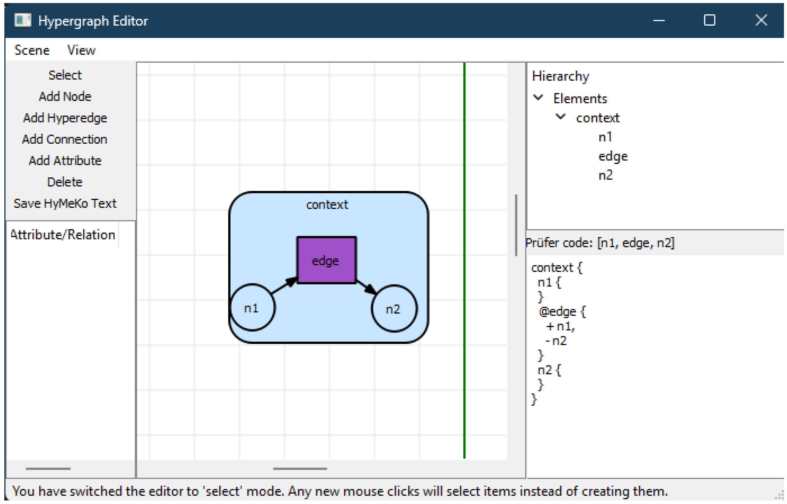
The markup language can be easily parsed using the PyLARK framework (python-lark), and enables the direct use of the parse tree in Python-based programs (following visitor or parse tree pattern). During this research, a utility program was developed, as depicted in Figure 4 to help describe hypergraph structures graphically, including physical structures. The utility program is based on the PyQt framework. The output of the editor program is a HyMeKo structure.
The article focuses on modeling and representing physical structures, particularly kinematic structures. The following synergies have been identified using the hypergraph convention as defined in Equation (1) representing a kinematic structure H ( V , E ) , and hyperarcs following Equation (2):
  • Hypervertices represent kinematic links (rigid or soft bodies). The attributes { A v i | v i V } provide the description of physical properties, not limited to the properties of the mass and the material. The visual and collision elements are treated as attribute enumerations (primitive geometries, or external meshes).
  • Hyperedges represent stress points or constraint points. Hyperedges represent physical constraints, such as joints, traction, and stress point. This article focuses on describing constrained systems that can be described using joints such as robotic kinematic structures. The definition of the axis (the direction of motion of the stress point) is defined as a reference to a previously defined hypergraph element.
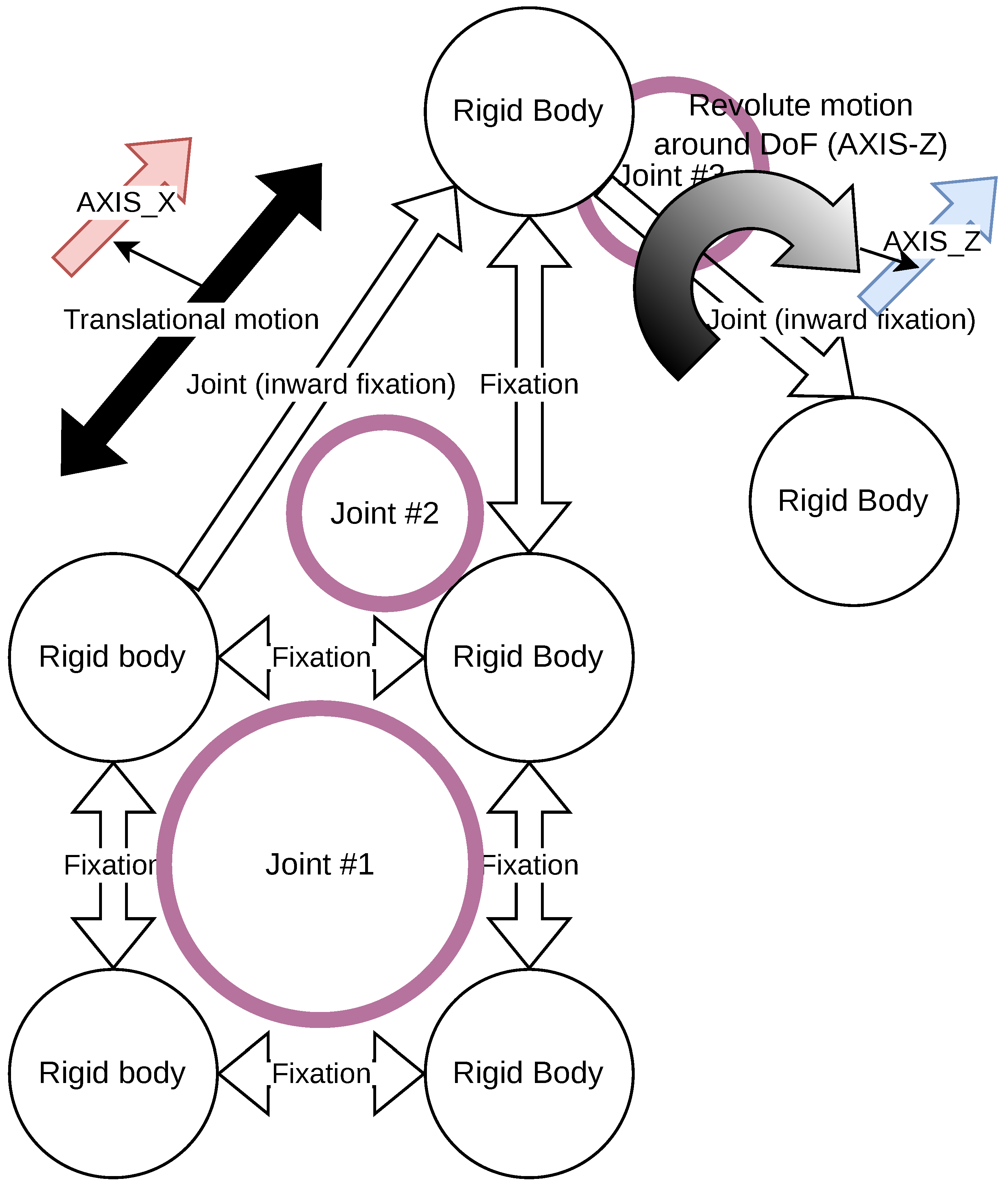
  • The convention allows for the description of complex kinematic structures, such as crane-like structures. An example of a crane-like kinematic structure, with a revolute joint at its end, is shown in Figure 5, showing the presence of fixation points and associated motion (prismatic, revolute) at each stress point. The root point can be fixed to the environment (as typical in many realistic scenarios), can be arbitrarily noted, or can be algorithmically computed using super-source calculation methods.
These rules are utilized during the modeling of a physical structure, providing equivalence pairs between physical elements and hypergraph elements. These equivalence pairs are summarized in Table 1, showing the following mappings between elements:
  • Rigid-body links are generally considered as hypervertices and can be directly mapped from the URDF and SDF links, following originally a kinematic tree convention.
  • Joints can be directly mapped to hypergraph edges, where each hyperarc defines a constraint point. A fixed point means transformation from a fixed point (the previous origin point). This can be easily converted to a Denavit-Hartenberg [34] and Hayati-Roberts [35] representation using substitutions and traversal.
  • While this transformation can introduce multiple axes (e.g., spherical joints), this article focuses on connecting link-pairs that can be directly derived from traditional prismatic and revolute joint connections.
  • The method simplifies describing spring-damp systems: in URDF, these descriptions require separate tags connecting joints with spring elements, while hypergraph descriptions can include spring-damper descriptions directly to the element (even one of the same type).
  • As depicted in Figure 5, the notation following the hypergraph formalism is capable of describing complex physical structures, depicting graph-like structures. The formalism can be further extended to describe Dirac structures and port-Hamiltonian systems, for example by describing hyperedges as energy interaction ports.
Besides the definition of physical elements and their relationship, simulators like Gazebo and MuJoCo require the following requirements, to load, visualize, and work with descriptions:
  • Visual elements of linkages, such as primitive geometries (e.g., sphere, cylinder, cube), externally loaded meshes, and color definitions to define the appearance of rigid bodies.
  • Definition of collisions through geometries (primitive types, external mesh), to provide the dynamic interaction between rigid bodies.
  • Inertia definitions of links following inertia tensor notation.
  • Optionally, the operational limits of the joints (e.g., prismatic and revolute limits).
URDF files are generated with the use of ChatGPT prompts, utilizing GPT-4.1, through extensive API calls to OpenAI. The LLM-based URDF generation process included the raw hypergraph-based description and text generation using an external large-language model (LLM) to generate the proper target description (e.g., URDF, SDF). The generated URDF is validated using XML-validation techniques to check whether the URDF contains the necessary elements, to enable the parsing and loading of descriptions into simulations. If the validation fails at any point, the description is regenerated. Furthermore, failure is indicated with a proper error message and indicator value. The generation method is depicted in Figure 6, with the following steps:
  • The process starts with a HyMeKo description of the robot, the LLM prompt, and the definition of the target format.
  • Based on the HyMeKo description, generate a target text output, such as URDF, MuJoCo-XML. The process is covered by Text generation using the Large-Language Model (LLM). Basically, it transforms the HyMeKo description into a parseable URDF/SDF description readable by Gazebo.
  • Validate the generated text output, whether it is a valid format in the target schema (e.g., XML, JSON). This step indicates success or failure of the generation with a proper feedback message.
  • Validate whether the URDF contains the necessary elements to load the elements and represent a robot. This is a multiple step process that checks the existence of mandatory elements in the resulting transformed description that are required for a working simulation:
    Existence of structural elements: verification that all links and joints in the transformed description are properly defined. Missing or incomplete elements may lead to invalid kinematic or dynamic models.
    Visual elements in links: confirmation that each link contains visual elements to allow the correct visualization of rigid bodies. A visual element typically specifies geometry (e.g., box, cylinder, mesh) and material properties such as color or texture. The validation process also checks for the consistency and correctness of the assigned values.
    Collision elements in links: verification that collision elements are present in all links to properly describe the physical interactions of rigid bodies. Collision elements often replicate the geometry of the visual description, but may be simplified to reduce computational complexity. Validation ensures that collision shapes are correctly defined and assigned with appropriate values.
    Inertial elements in links: verify that inertial properties are provided for all links to accurately describe mass distribution and rotational dynamics. Inertial properties are typically expressed via an inertia tensor. The validation also verifies that values are physically meaningful (e.g., positive-definite inertia matrices, nonzero mass).
    Correspondence of link definitions: ensure consistency in the naming and referencing of links in the description. This includes verifying that all referenced links exist and that there are no duplicated or conflicting identifiers.
    Correspondence of joint definitions: check that joint elements are defined with proper names and attributes, and that parent–child relationships are correctly established. Validation also includes ensuring that each joint references valid links and that the specified degrees of freedom match the intended kinematic constraints.
  • If an error is reached at any validation step, return to the first step and try to generate a new description.
  • If the process runs without any errors, the transformed description can be loaded into the target simulation.
The first validation step is to ensure that the generated URDF is a syntactically correct XML file, i.e., a fully parseable description without structural or formatting errors. Once the XML validity is confirmed, the validation process performs a set of semantic checks on the URDF file (by inspecting the XML elements) to verify that the model is both loadable and correctly visualizable in simulation environments:
  • Link element validation: check that every link contains the required visual, collision, and inertial elements, with consistent and physically meaningful values. This includes verifying geometry definitions (e.g., box, cylinder, mesh), correct dimensions, and valid inertial parameters.
  • Joint element validation: ensure that each joint element specifies both a parent and a child link, and that the declared joint type (e.g., revolute, prismatic, fixed) is consistent with the intended kinematic relationship. In addition, degrees of freedom and axis definitions are verified for correctness.
  • Structural consistency: confirm that the number of links and joints matches the specification provided by the original formalism. This step guarantees that no links or joints are missing, duplicated, or misreferenced, thereby preserving the integrity of the kinematic chain.
These checks collectively ensure that the URDF file can be successfully loaded into simulators, rendered for visualization, and simulated with kinematic structures that have the correct topology, dimensions, and assigned physical properties.

5. Results and Discussion

URDF and SDF are widely distributed XML-based formats in robotics applications and recently in knowledge representations of robots [36]. They capture kinematic structures in a tree-based fashion, following a scene graph construction. These formats are based on an XML schema, therefore, easily parsed using any XML parser library. Although these descriptions are straightforward to use, resulting in a verbose textual representation of kinematic structures with duplicate relational definitions. Furthermore, elements are listed linearly, each element listed in a single-layer hierarchy. MuJoCo XML follows an even more stricter kinematic tree approach, embedding elements under kinematic links in a parent-child relationship.
The dynamic elements and actuator-sensor interface is given with a verbose and repetitive structure, listing at least two relationship elements, and listing additional parameters. URDF/SDF introduce redundancy by re-specifying relationships and attributes, with derived specifications duplicating properties from common definitions.

5.1. Description of Robots

The description of robots with HyMeKo follows the multirelational approach using directed hypergraphs, in which the relationship between elements is not explicitly defined in a nested structure, but allows flexible placement of elements in a relational structure. The parent-child relationship in the kinematic description is derived from the indicated hyperarc directionality:
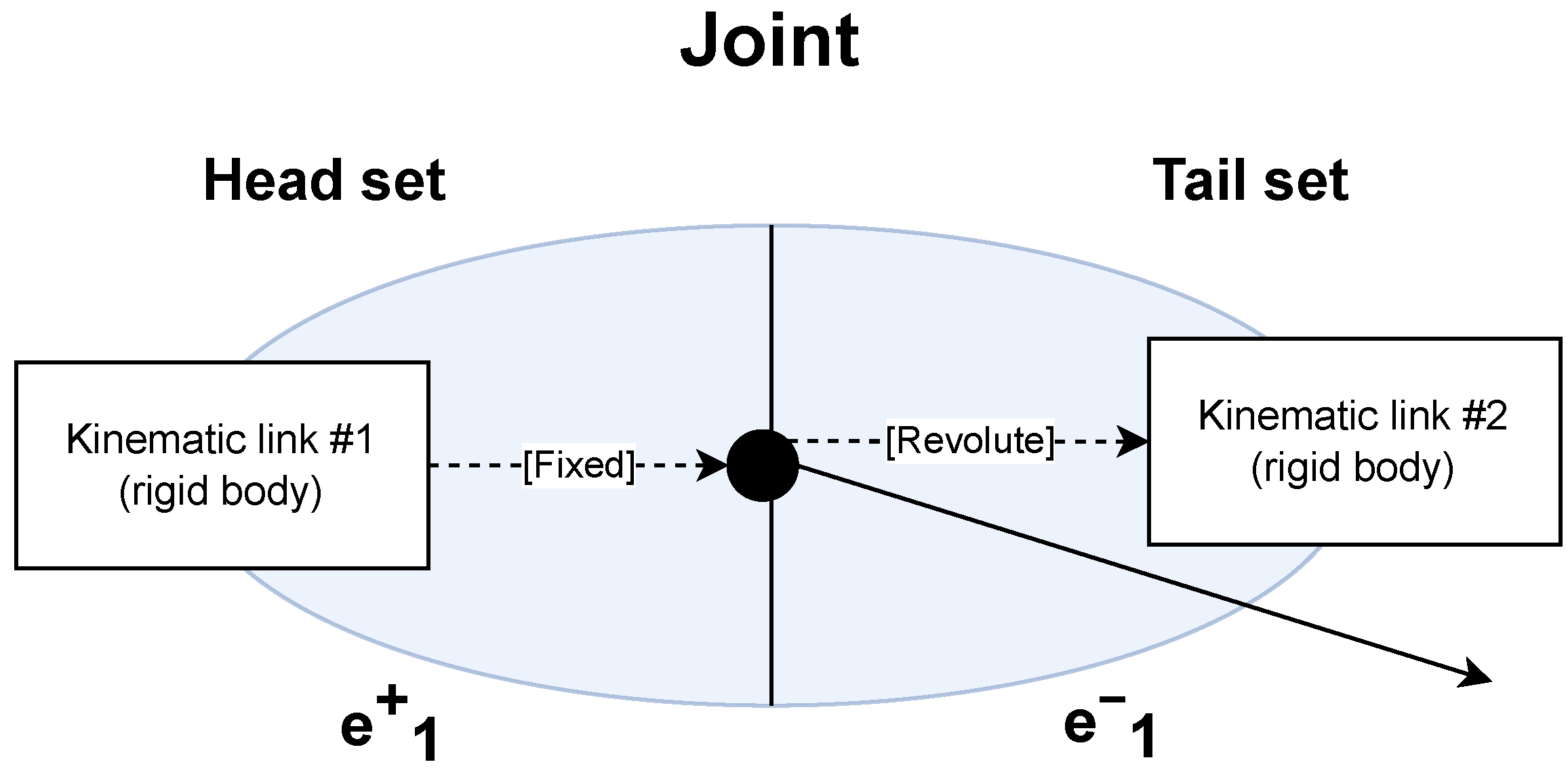
  • ‘+’ indicates tail starting in a kinematic link and head ending in the hyperedge ( i , e i ) e i + , kinematically in the joint.
  • ‘−’ otherwise indicates the tail that starts in the kinematic joint and ends in a kinematic link, ( e i , i ) e i .
  • Hyperarcs therefore translate to the definition of fixation points and to the defining of the axis (and type) of the movement alongside the fixation. The fixed points also define the translation and orientation provided by the joint.
The root and the fixation points are indicated by the incoming hyperarcs, and the freedom (rotational and prismatic motions) are indicated by the outgoing, tail hyperarcs. The methodology is depicted in Figure 7, showing how the kinematic links are related and fixed through the kinematic joints.
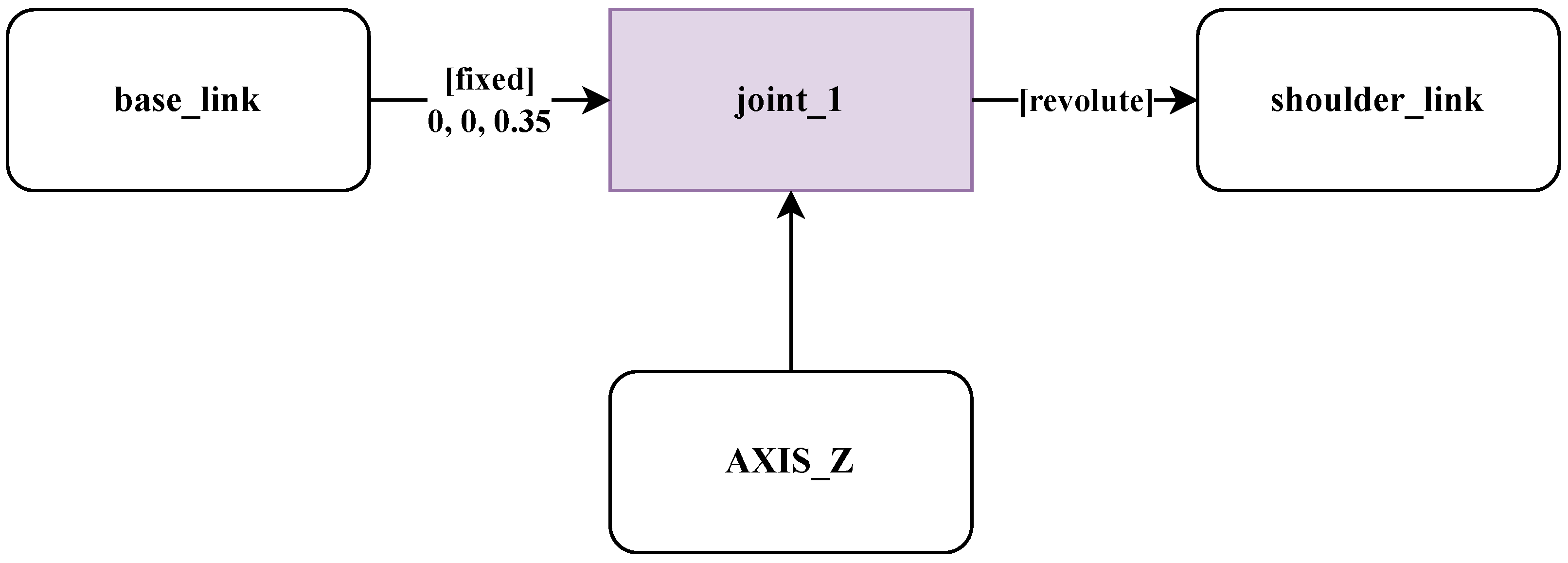
A very simple example that describes a minimal robot, using HyMeKo is provided in Listing 2. The same robot is also represented as a hypergraph in Figure 8 as the 2-factor decomposition of the hypergraph description. The simple robot has two-links with one revolute joint on the Z-axis (following traditional right-hand coordinate frame convention). In this representational example, no physical properties are assigned to the kinematic links, the joint defines the geometric disposition of the second link relative to the first link. The new description format has multiple advantages over conventional URDF-based modeling:
  • The equivalent URDF description is 48 characters long (listed in Listing 3), and the HyMeKo description is a total of 21 characters long.
  • The edge definitions are flexible, they can represent edges, control definitions, or sensor connections (typical extensions in robotic descriptions, like joint state publishers, control parameters), besides the traditional definition of kinematic joint elements.
  • The structured definition allows input for large-language models, but human users are also capable of using it and easily explaining it.
Listing 2. Very simple example written in HyMeKo of two links and one joint.
1simple_robot {
2    AXIS_Z {}
3    shoulder_link {}
4    @joint_1 { [0.0 , 0.0 , 0.35] + base_link , - shoulder_link , + AXIS_Z }
5    base_link {}
6}
Listing 3. Equal of the very simple robot in URDF, generated from the simple HyMeKo description.
1<?xml version="1.0"?>
2<robot name="shoulder_robot">
3  <!-- Base Link -->
4  <link name="base_link"/>
5  <link name="shoulder_link"/>
6  <joint name="joint_1" type="revolute">
7    <origin xyz="0.0 0.0 0.35" rpy="0 0 0"/>
8    <parent link="base_link"/>
9    <child link="shoulder_link"/>  <axis xyz="0 0 1"/>
10    <limit effort="10.0" velocity="1.0" lower="-3.14" upper="3.14"/>
11  </joint>
12</robot>
A second application modeled an SCARA-like robot [20] with two joints in a two-dimensional plane (traditional XY plane) and three kinematic links (base link, shoulder link, wrist link). The robot was limited to moving in two dimensions using two revolute joints, which was not equipped with a prismatic tool effector at the end. The resulting description was still much smaller (character length of 89 as depicted in Listing 4, compared to URDF 165), resulting in a viable description generated directly by LLM directly.
Listing 4. HyMeKo description of a SCARA robot of three links and two joints.
1scara_robot {
2  base_link {
3    mass = 2.0
4    translation = [0.0, 0.0, 0.3]
5    geometry {  type = cylinder
6      dimensions = [0.1, 0.6]
7    }
8  }
9  shoulder_link {
10    mass = 1.0
11    translation = [0.3, 0.0, 0.0]
12    rotation = [0, 90, 0]
13    geometry { type = cylinder
14      dimensions = [0.1, 0.6]
15      rotation = [0, 90, 0]
16    }
17  }
18  @joint_1 {
19    [[0.0, 0.0, 0.63],[0.0, 0, 90]] + base_link,
20    REV - shoulder_link, + AXIS_Z
21  }
22  wrist_link {
23    mass = 1.0
24    translation = [0.3, 0.0, 0.0]
25    rotation = [0.0, 90, 0.0]
26    geometry {
27      type = cylinder
28      dimensions = [0.1, 0.5]
29    }
30  }
31  @joint_2 { [[0.5, 0.0, 0.0],[0.0, 0, 0]] + shoulder_link, REV - wrist_link, + AXIS_Z }
32  AXIS_Z {}AXIS_Y {}AXIS_X {}
33}
The kinematic links in the SCARA-like robot are now attributed with physical and geometric properties:
  • The base link (first kinematic link) has a mass of 2 kg and all other kinematic elements have a mass of 1 kg each.
  • Each cylinder has a radius of 0.1 m. The wrist link has a length of 0.5 m, while the other link’s length is 0.6 m.
  • The kinematic links are rotated accordingly and translated to align to dimension (the origin of geometries in simulators starts in the center of the geometry).
  • The description and the associated generators allow omitting the collision geometry description, which is useful for draft robots (built from primitive geometries, like cubes, cylinders). For real robots, an approximate mesh is used for collision, or similarly the visual mesh is used (typically with robots composed of convex geometries).
  • The revolute property is defined as a hyperarc property of the revolute constant. This also allows for the description of exotic joint connections.
The joints are now attributed with the following properties:
  • The joints are both revolute joints, each fixed to the previous kinematic link.
  • The joints rotate around the Z-axis, perpendicular to the robot motion plane.
  • The base link is the root, fixed to the ground.
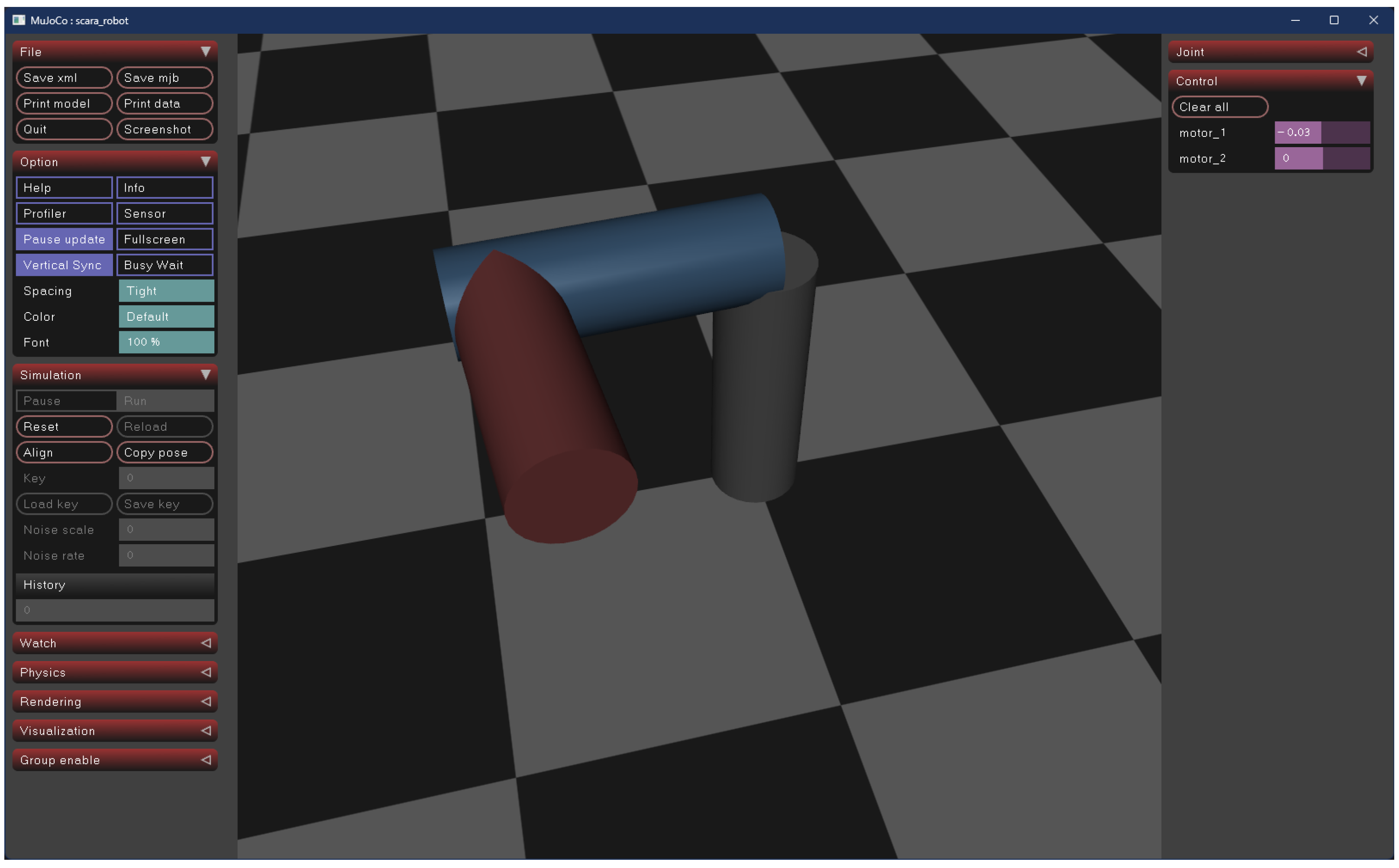
The hypergraph-based description of the two-joint SCARA-like robot is graphically depicted in Figure 9. The visualization was concluded with the help of the URDF-visualizer plugin in Visual Studio Code 1.104.3 and MuJoCo 3.3. The MuJoCo visualization is shown in Figure 10. 100 consecutive generation runs with LLM (ChatGPT-4.1) resulted in multiple usable URDF descriptions, resulting in no validation errors (i.e., the descriptions could always be loaded). Further measurements were performed with a larger sample of 216 measurements (a total of 300 measurements), with the following results:
  • All descriptions could be loaded and followed the URDF schema well.
  • In most cases, the descriptions generated included all the required elements, with the proper dimensions and parameters.
  • The raw generated descriptions were in some cases longer and in some cases shorter, missing or hallucinated some elements not present in the generated description.
Based on the description, the Denavit-Hartenberg parameters can be easily derived (summarized in Table 2), with two rows and using the standard convention θ i ,   d i ,   a i ,   α i . With some remarks:
  • Joint 1 θ 1 : axis Z, the translation relative to the base link is z = 0.63 m and rotated around the origin by π / 2 (on the Z axis Z). So, the offset ( d 1 ) is 0.63 m, the link length is 0.3 m, with the twist angle π / 2 .
  • Joint 2 θ 2 : axis Z, the translation relative to the shoulder link is x = 0.5 m, with no apparent twist. So, no offset, with a link length 0.5 m.
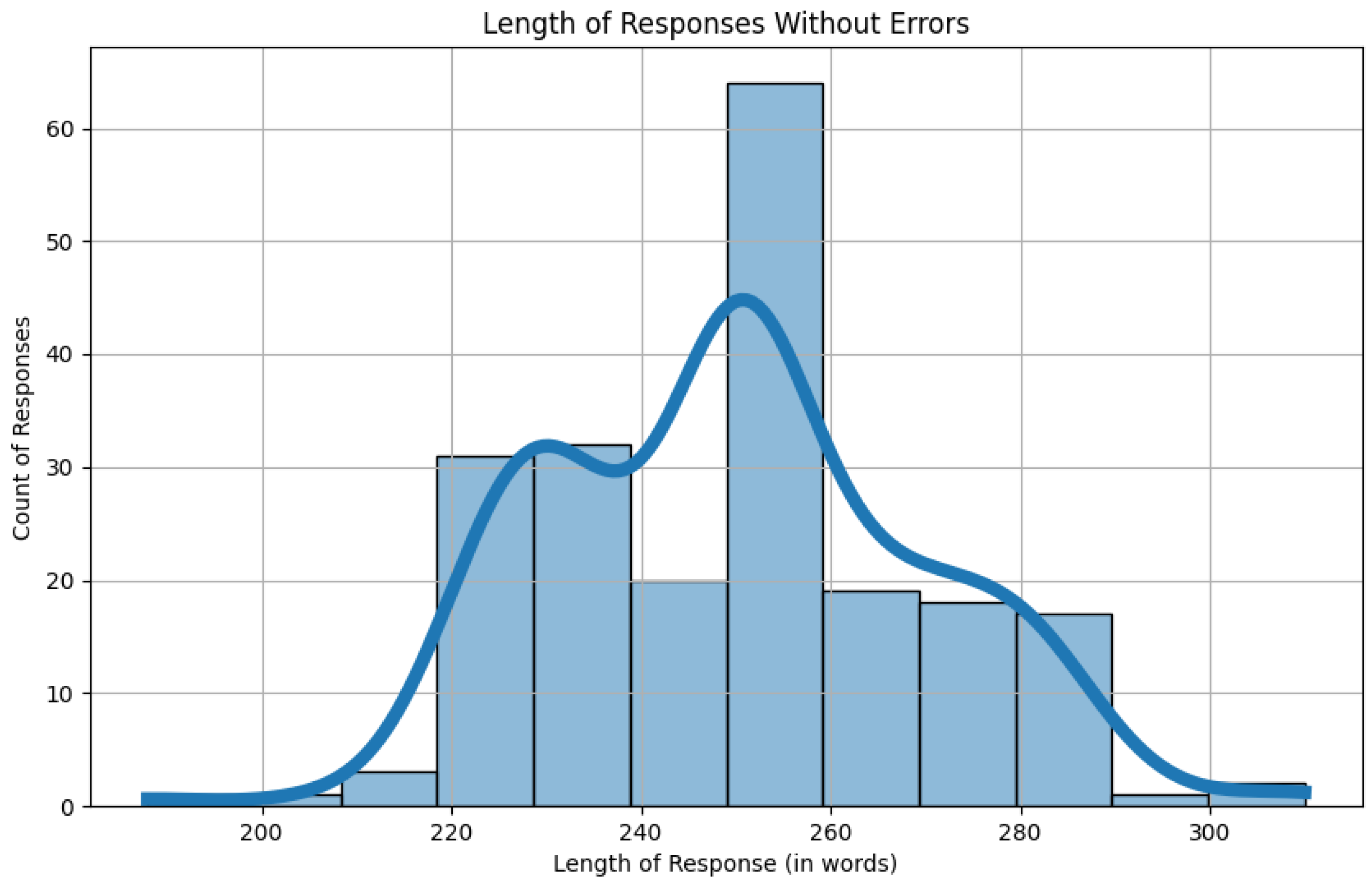
The distribution lengths of 216 measurements are shown in Figure 11 with a kernel destiny estimation of the lengths. It has a mean value of 252 characters and a standard deviation of 23 characters. The minimal length is 188 characters, with a maximal outlier length of 373 characters. As depicted with the distribution of lengths, most lengths are distributed within the character length range of 220 and 290 characters, with longer and shorter descriptions much less frequent. The distribution of the length of the generated descriptions is best fit with nonparametric methods. A simple normal distribution cannot fit the distribution properly.
The proposed format is flexible enough to include extension to soft robotics or prepare FEM analysis of aeronautical devices [37]. Describing underactuated systems, such as quadrocopters, is possible, but it requires further research, as it is not the current focus of this paper.

5.2. Describing a Quarter Vehicle Model

To demonstrate the broader applicability of the hypergraph-based model, fundamental examples from vehicle engineering can also be formulated and validated. The principles of dynamic modeling in vehicle systems closely resemble those of robotics, which typically incorporates joints, springs, dampers, and inertial components. In this context, the hypergraph representation can be defined with the following considerations:
  • Physical elements, such as springs, masses (i.e., rigid bodies), and dampers, are represented as hypervertices.
  • Hyperedges establish the dynamic relationships among these elements, while hyperarcs specify the directions of interaction, analogous to force representations in a free-body diagram.
The widespread model used in vehicle dynamic studies, the quarter vehicle vehicle model can be described using the introduced notation and approach (expressed with HyMeKo description Listing 5), depicted graphically using the hypergraph-based modeling approach in Figure 12, following the traditional equation [38], where:
  • F r o a d is the external excitation force applied by the road profile (input disturbance).
  • m is the sprung (or unsprung) mass represented in the model.
  • k is the spring constant of the suspension spring, describing the stiffness of the system.
  • c is the damping constant of the damper, representing energy dissipation.
  • x is the displacement state variable, with x ˙ denoting velocity and x ¨ denoting acceleration.
In summary, the control equation formulated in Equation (3), following a damper-spring physical model, following the definition in vehicle dynamics textbooks [38].
m x ¨ + c x ˙ + k x = F r o a d
In the case of the quarter-vehicle model, the hypergraph representation consists of a single hyperedge that connects the system elements as follows:
  • The chassis acts as a fixed reference point (stationary force), represented by a hyperarc originating from the chassis vertex and terminating at the joint edge.
  • The damper represents a dissipative force, with a hyperarc starting at the damper element and ending at the joint edge.
  • The spring provides the restoring force, modeled by a hyperarc that originates at the joint and terminates at the spring element.
  • The mass is attached to the joint, represented by a hyperarc starting at the joint and ending at the mass element.
Listing 5. HyMeKo-based description of quarter-vehicle model fixed to the chassis.
1quarter_vehicle_model {
2  spring { spring_constant = 50000.0 }
3  damping { damping_const = 1000.0 }
4  link {  mass = 50.0 }
5  chassis {  }
6  @joint {
7    + chassis, - link, + damping, - spring
8  }
9}
In this introductory example, the description (depicted Listing 5) contains the parameters as attributes defined as part of the hypervertcies—similar to the physical parameters assigned to robot descriptions. In this sense, the quarter model has the following parameters:
  • A mass: m = 50 kg.
  • A spring constant of: k = 50 , 000 N/m
  • A damper constant of: c = 1000 Ns/m
  • The fixed point is the chassis of the vehicle.
Based on the description, the following system variables can be derived (translation and velocity, respectively) using proper substitution into Equation (3) ( z ( t ) is the displacement function):
x 1 ( t ) = z ( t )
x 2 ( t ) = z ˙ ( t )
With the substitution as reassigned to the state-space description of the quarter-model vehicle system [38]:
x 1 ˙ = x 2
x 2 ˙ = 1 m [ c x 2 k x 1 + F ( t ) ]
And to the matrix-based description if including the input force F ( t ) : = [ z r , z ˙ r ] T ( z r indicates road disturbances), Equation (8) substituting the constants and the general state-space relationship in Equation (9) following the standard vehicle dynamics model [38]:
x 1 ˙ x 2 ˙ = 0 1 k m c m x 1 x 2 + 0 0 k m c m F ( t )
x ˙ = A x + B z r z r ˙
With substitution of the parameter values, the input matrices of the state space description with the constants were directly substituted into the state-space matrices in Equation (10):
A = 0 1 1000 20 ,   B = 0 0 1000 20
And the substituted output definition of the system, with instantaneous displacement equal to the input of the system and the x 1 state variable in Equations (11) and (12) defines the output matrices:
y = x 1 = z ( t )
C = [ 1 , 0 ] ,   D = 0
The Simulink model is depicted in Figure 13, using the state space representation of the quarter-vehicle model. The time-based plot (mass displacement) is a result of the simulation of pulse obstacles on a rough road.
The simulation parameters of the quarter vehicle model are summarized in Table 3, which denotes the properties of the input signal, the general properties of the simulation, and the additive noise properties.
The paper investigates the basic modeling of dynamic systems and can detail the simulation further by including:
  • Evaluating and modeling disturbances of the system from the environment. This could further point to modeling the interaction between the system and the environment.
  • The paper currently investigates a classical mode scheme and advanced controllers can be included. These controllers can be further modeled with the descriptions.
  • Tuning of the system using the description and the parameters defined is possible (e.g., through parameter search), but this is the scope of further research.

5.3. Statistical Summary

With the newly proposed usage of the HyMeKo markup language, kinematic and dynamic modeling of robots has become simpler and more concise. The markup language can also be readily understood by LLMs (e.g., ChatGPT), as demonstrated by consecutive generations of robot descriptions.
The main goal of this paper is to provide a description format that can describe complex kinematic structures and is also more concise and shorter than the widespread MuJoCo-XML and URDF formats. Given that the full length of the HyMeKo description was 101 in the case of the SCARA-like robot and 71 in the case of the simple linkage. From the raw results of description generation, a hypothesis can be grounded on whether:
  • Test whether the HyMeKo description is significantly shorter than the URDF and MuJoCo-XML.
  • The full HyMeKo description length was respectively 71 and 101 characters long, and a null hypothesis can be grounded: Are the generated URDF and MuJoCo descriptions smaller than the Hymeko description length?
Using the Wilcoxon test, on the slightly left-distorted normal distribution, the null hypothesis can be checked. Using one-sided Wilcoxon in the measurements of the generated lengths as expressed in Section 5.1 for both the simple linkage definition and the SCARA-like robot. The basic descriptive statistics reported are depicted in Table 4.
On the other hand, a simple zero-shot prompt have been used for generation, not taking into account the feedback (without chain), just executing the generation based on the HyMeKo description (in the measurement’s case, on a SCARA robot). OpenAI GPT4.1 scored relatively low on generating correct (i.e., descriptions containing all elements and in a correct way), verified outputs, using the prompt below (Listing 6) for URDF:
Listing 6. Zeros-shot prompt used for generating URDFs with LLMs (ChatGPT4.1).
1You are an expert in robotics.
2Convert the following HyMeKo robot description into a valid URDF file.
3Don ’t forget to include all required elements.
4Only output the URDF XML, nothing else:\n
For MuJoCo, a bit more detailed prompt (Listing 7) is required to ensure elements, such as mass, color, are included with the element definitions.
Listing 7. Zeros-shot prompt used for generating MuJoCo XML with LLMs (ChatGPT4.1).
1You are an expert in robotics. Convert the following HyMeKo robot
  description
2into a valid MuJoCo file. Compiler should use local coordinates. Don ’t
  forget to include all required elements.
3Include mass in geometry. Include color definition directly to links, don ’t
   include visual elements in the beginning.
4Only output the MuJoCo XML, nothing else:\n
With this prompt, GPT4.1 generated 245 valid URDF files out of 300 attempts using the HyMeKo prompt that describes the SCARA-like robot and 272 correct files in the case of MuJoCo. GPT4.1-mini attempts at generating URDF files could get the structure right, but not the specific values.
Regarding the correctness and efficiency of the generation process, loop closure must be enhanced: for example, with a two-tier generation (prompting), one focusing on the structure generation and one on substituting and verifying the substituted values (LLMs are prone to make mistakes on numerical values). The results on the Other alternative are the development of a direct URDF description generation from HyMeKo, but it requires the development of a separate plugin for the generation of description files.
MuJoCo-XML as are generated with a lower error rate, and generally MuJoCo XMLs are more compact than URDF descriptions (due to the nested structure), thus there is a lower decrease in size with HyMeKo. The results obtained are summarized in Table 5. In summary, both in the case of URDF and MuJoCo XML, the acquired Wilcoxon p-values confirm the following findings on over 300 generated samples.
  • In the case of simple linkage, the Wilcoxon p-value was 8.5 × 10 49 in the case of URDF and 6.4 × 10 29 in the case of MuJoCo XML, with 56% and 25%, respectively. This means that the HyMeKo description is significantly shorter.
  • In the case of the SCARA-like robot, the Wilcoxon p-value was 2.3 × 10 36 in the case of URDF and 2.7 × 10 43 in the case of MuJoCo XML, with 50% and 21.7% character reduction, respectively. Therefore, the HyMeKo description is significantly shorter in this case as well.
These reported statistical values conclude a very small chance of generating a description that is shorter than the HyMeKo description. Only validated generated descriptions containing all required elements were considered in the statistics. Therefore, HyMeKo descriptions will be statistically shorter. The results also demonstrate that the description is both explainable for the LLMs and human users alike, without the explicit need of a generator plugin between text representations.
Similar graph-based approaches on input data (graph-of-thought prompting) are prevalent in bioinformatics applications [39], and structured prompting with JSON or XML input is a widespread method of overcoming hallucinations [40] and generating structured formalized data [41].

5.4. Limitations of This Study

It is important to note that the study concentrated on simple examples such as minimal SCARA robots and simple two-link robots. More complex robots (such as an anthropomorphic 6-DOF robot and humanoid robots) should also be modeled and generated.
The study uses LLMs with simple zero-shot prompting, so it remains susceptible to hallucinations. Reliability can be improved with few-shot templates, retrieval-augmented prompts, and constrained decoding against the HyMeKo grammar. A round-trip verifier could help detect omissions and spurious elements. Lower temperature/top-p settings and a lightweight planner–executor loop further improve fidelity.
MATLAB-based model generation and validation are in an early stage. A simple approach is used to model a controller and its interaction with the environment. The environment and controller models should be included in future versions of the modeling approach, alongside the disturbance description. Furthermore, additional investigation is required to systematically produce MATLAB and Simulink descriptions.
Additional environments, such as CARLASim, and complex structures in MuJoCo (e.g., humanoid robots) should also be further tested.

6. Conclusions

This paper proposes the HyMeKo framework for dynamic modeling, showing that hypergraph-based representations can simplify and enrich the modeling of robotic kinematic and dynamic structures. Compared to existing formats, it offers more compact and modular descriptions that are well suited to both human users and LLMs. The theoretical background of the methodology is based on directed hypergraphs, which allow the description of many-to-many relationships and complex, potentially exotic kinematic structures (such as parallel robots, tripods). This paper demonstrates the approach using three examples: a two-link, one-joint robot, a minimalistic SCARA-like robot, and a quarter-vehicle model. Across these examples, HyMeKo descriptions are about 50% shorter than URDF and roughly 20% shorter than MuJoCo XML. The results also show that descriptions are easily interpretable by both humans and LLM agents, without the need for a custom plug-in between text representations (e.g., HyMeKo to URDF).
Limitations include the need to evaluate additional domains and integrate more simulation environments (e.g., CARLASim). Currently, automatic generation targets URDF and MuJoCo. Other formats, such as Universal Scene Description, are left for future work. The workflow remains susceptible to LLM hallucinations, occasionally adding or omitting elements related to the source description. The impact of the proposed format on reducing hallucinations merits further study, together with prompting strategies beyond zero-shot (e.g., few-shot, chain-of-thought, graph-of-thought).
Future work will address these challenges and extend the approach to multi-physics co-simulation and real-time control. We will place greater emphasis on mechanical system formulation following Dirac-structure and port-Hamiltonian methodologies, potentially generalizing the formalism to systems modeled as interconnections of energy-storing and energy-dissipating components governed by a Hamiltonian. This paper considered only single kinematic chains; more complex structures (e.g., humanoid robots) will be analyzed next. We also plan to explore reinforcement-based hierarchical generation with local LLMs, using smaller models such as Gemma (3/3n), Mistral, Llama, and EuroLLM.

Author Contributions

Conceptualization, C.H.; methodology, C.H.; software, C.H.; validation, C.H., N.H.; formal analysis, C.H.; investigation, C.H.; resources, C.H.; data curation, C.H.; writing—original draft preparation, C.H.; writing—review and editing, N.H.; visualization, C.H.; supervision, N.H. All authors have read and agreed to the published version of the manuscript.

Funding

Supported by the EKÖP-24-4-I-SZE University research fellowship program of the Ministry for Culture and Innovation from the source of the National Research, Development and Innovation Fund.

Institutional Review Board Statement

Not applicable.

Informed Consent Statement

Not applicable.

Data Availability Statement

The data is available, at the public GitHub repositories of the HyMeKo framework.

Conflicts of Interest

The authors declare no conflicts of interest.

References

  1. Tola, D.; Corke, P. Understanding URDF: A Dataset and Analysis. arXiv 2023, arXiv:2308.00514. [Google Scholar] [CrossRef]
  2. Ivanou, M.; Mikhel, S.; Savin, S. Robot description formats and approaches: Review. In Proceedings of the 2021 International Conference “Nonlinearity, Information and Robotics” (NIR), Innopolis, Russia, 26–29 August 2021; pp. 1–5. [Google Scholar] [CrossRef]
  3. Todorov, E.; Erez, T.; Tassa, Y. MuJoCo: A physics engine for model-based control. In Proceedings of the 2012 IEEE/RSJ International Conference on Intelligent Robots and Systems, Vilamoura-Algarve, Portugal, 7–12 October 2012; pp. 5026–5033. [Google Scholar] [CrossRef]
  4. Bretto, A. Hypergraph Theory: An Introduction; Springer Publishing Company, Inc.: Berlin/Heidelberg, Germany, 2013. [Google Scholar]
  5. Dai, Q.; Gao, Y. Mathematical Foundations of Hypergraph. In Hypergraph Computation; Springer Nature: Singapore, 2023; pp. 19–40. [Google Scholar] [CrossRef]
  6. Thompson, H.S.; Lilley, C. XML Media Types; Series: Request for Comments Published: RFC 7303; Internet Engineering Task Force: Fremont, CA, USA, 2014; 35p. [Google Scholar] [CrossRef]
  7. Bray, T. The JavaScript Object Notation (JSON) Data Interchange Format; Internet Engineering Task Force, Series: Request for Comments Published: RFC 8259; Internet Engineering Task Force: Fremont, CA, USA, 2017; 16p. [Google Scholar] [CrossRef]
  8. Hajdu, C.; Csapó, Á. Generative Hypergraph-based Kinematic Models for Virtual-Reality Applications. In Proceedings of the 2022 1st IEEE International Conference on Cognitive Aspects of Virtual Reality (CVR), Budapest, Hungary, 11–12 May 2022; pp. 11–16. [Google Scholar] [CrossRef]
  9. Shetty, S.S.; Bhat, K.A. Spectral Theory of Hypergraphs: A Survey. arXiv 2025, arXiv:2507.13664. [Google Scholar] [CrossRef]
  10. Banerjee, A. On the spectrum of hypergraphs. Linear Algebra Its Appl. 2021, 614, 82–110. [Google Scholar] [CrossRef]
  11. Mulas, R.; Horak, D.; Jost, J. Graphs, Simplicial Complexes and Hypergraphs: Spectral Theory and Topology. In Higher-Order Systems; Battiston, F., Petri, G., Eds.; Springer International Publishing: Cham, Switzerland, 2022; pp. 1–58. [Google Scholar] [CrossRef]
  12. Zhou, J.; Cui, G.; Zhang, Z.; Yang, C.; Liu, Z.; Sun, M. Graph Neural Networks: A Review of Methods and Applications. arXiv 2018, arXiv:1812.08434. [Google Scholar] [CrossRef]
  13. Wang, F.; Pena-Pena, K.; Qian, W.; Arce, G. T-HyperGNNs: Hypergraph Neural Networks Via Tensor Representations. IEEE Trans. Neural Netw. Learn. Syst. 2024, 36, 5044–5058. [Google Scholar] [CrossRef]
  14. Courant, T.J. Dirac Manifolds. Trans. Am. Math. Soc. 1990, 319, 631–661. [Google Scholar] [CrossRef]
  15. van der Schaft, A.; Maschke, B. Hamiltonian formulation of distributed-parameter systems with boundary energy flow. J. Geom. Phys. 2002, 42, 166–194. [Google Scholar] [CrossRef]
  16. Duindam, V.; Macchelli, A.; Stramigioli, S.; Bruyninckx, H. Modeling and Control of Complex Physical Systems: The Port-Hhamiltonian Approach; Springer: Berlin/Heidelberg, Germany, 2009. [Google Scholar] [CrossRef]
  17. Schaft, A. Port-Hamiltonian systems: An introductory survey. In Proceedings of the International Congress of Mathematicians; European Mathematical Society: Helsinki, Finland, 2006; Volume 3, pp. 1339–1366. ISBN 978-3-03719-022-7. [Google Scholar]
  18. Hajdu, C.; Csapó, Á.B. Hypergraph-based Modeling of Cognitive Dataflow Systems. In Proceedings of the IEEE CogInfoCom 2024: 2024 15th IEEE International Conference on Cognitive Infocommunications, Tokyo, Japan, 16–18 September 2024; p. 37. [Google Scholar]
  19. Boschetti, G.; Sinico, T. Dynamic Modeling and Parameter Identification of a SCARA Robot Including Nonlinear Friction and Ball Screw Spline Coupling. J. Intell. Robot. Syst. 2025, 111, 96. [Google Scholar] [CrossRef]
  20. Kapusi, T.P.; Erdei, T.I.; Husi, G.; Hajdu, A. Application of Deep Learning in the Deployment of an Industrial SCARA Machine for Real-Time Object Detection. Robotics 2022, 11, 69. [Google Scholar] [CrossRef]
  21. Bollobás, B. Combinatorics: Set Systems, Hypergraphs, Families of Vectors, and Combinatorial Probability; Cambridge University Press: New York, NY, USA, 1986. [Google Scholar]
  22. Feng, Y.; You, H.; Zhang, Z.; Ji, R.; Gao, Y. Hypergraph Neural Networks. Proc. AAAI Conf. Artif. Intell. 2018, 33, 3558–3565. [Google Scholar] [CrossRef]
  23. Lin, S.; Xiao, G.; Yan, Y.; Suter, D.; Wang, H. Hypergraph Optimization for Multi-Structural Geometric Model Fitting. Proc. AAAI Conf. Artif. Intell. 2019, 33, 8730–8737. [Google Scholar] [CrossRef]
  24. Shang, Z.; Chen, L. MSHyper: Multi-Scale Hypergraph Transformer for Long-Range Time Series Forecasting. arXiv 2024, arXiv:2401.09261. [Google Scholar]
  25. Tola, D.; Corke, P. Understanding URDF: A Survey Based on User Experience. In Proceedings of the 2023 IEEE 19th International Conference on Automation Science and Engineering (CASE), Auckland, New Zealand, 26–30 August 2023. [Google Scholar]
  26. Koenig, N.; Howard, A. Design and Use Paradigms for Gazebo, An Open-Source Multi-Robot Simulator. In Proceedings of the IEEE/RSJ International Conference on Intelligent Robots and Systems, Sendai, Japan, 28 September–2 October 2004; pp. 2149–2154. [Google Scholar]
  27. You, J.; Wu, Z.; Wei, W.; Li, N.; Yang, Y. Evolution of Industrial Robots from the Perspective of the Metaverse: Integration of Virtual and Physical Realities and Human–Robot Collaboration. Appl. Sci. 2024, 14, 6369. [Google Scholar] [CrossRef]
  28. Albergo, N.; Rathi, V.; Ore, J.P. Understanding Xacro Misunderstandings. arXiv 2021, arXiv:2109.09694. [Google Scholar]
  29. Zhao, Z.; Yang, K.; Guo, J. Link Prediction with Hypergraphs via Network Embedding. Appl. Sci. 2023, 13, 523. [Google Scholar] [CrossRef]
  30. Champion, K.; Lusch, B.; Kutz, J.N.; Brunton, S.L. Data-driven discovery of coordinates and governing equations. Proc. Natl. Acad. Sci. USA 2019, 116, 22445–22451. [Google Scholar] [CrossRef]
  31. Brugnoli, A.; Haine, G.; Matignon, D. Explicit structure-preserving discretization of port-Hamiltonian systems with mixed boundary control. IFAC-PapersOnLine 2022, 55, 418–423. [Google Scholar] [CrossRef]
  32. Yadati, N.; Nimishakavi, M.; Yadav, P.; Nitin, V.; Louis, A.; Talukdar, P. HyperGCN: A New Method of Training Graph Convolutional Networks on Hypergraphs. arXiv 2019, arXiv:1809.02589. [Google Scholar] [CrossRef]
  33. Banerjee, A. On the spectrum of hypergraphs. arXiv 2019, arXiv:1711.09356. [Google Scholar] [CrossRef]
  34. Denavit, J.; Hartenberg, R.S. A Kinematic Notation for Lower-Pair Mechanisms Based on Matrices. J. Appl. Mech. 2021, 22, 215–221. [Google Scholar] [CrossRef]
  35. Hayati, S.; Mirmirani, M. Improving the absolute positioning accuracy of robot manipulators. J. Robot. Syst. 1985, 2, 397–413. [Google Scholar] [CrossRef]
  36. Nguyen, G.H.; Beßler, D.; Stelter, S.; Pomarlan, M.; Beetz, M. Translating Universal Scene Descriptions into Knowledge Graphs for Robotic Environment. In Proceedings of the 2024 IEEE International Conference on Robotics and Automation (ICRA), Yokohama, Japan, 13–17 May 2023; pp. 9389–9395. [Google Scholar]
  37. Hegyi, N.; Jósvai, J.; Fekete, G. Numerical and Experimental Analysis of Impact Force and Impact Duration with Regard to Radiosondes: Is a PUR Foam Shell an Effective Solution? Appl. Mech. 2025, 6, 19. [Google Scholar] [CrossRef]
  38. Rajamani, R. Vehicle Dynamics and Control; Mechanical Engineering Series; Springer: Berlin/Heidelberg, Germany, 2011. [Google Scholar]
  39. Matsumoto, N.; Choi, H.; Moran, J.; Hernandez, M.E.; Venkatesan, M.; Li, X.; Chang, J.H.; Wang, P.; Moore, J.H. ESCARGOT: An AI agent leveraging large language models, dynamic graph of thoughts, and biomedical knowledge graphs for enhanced reasoning. Bioinformatics 2025, 41, btaf031. [Google Scholar] [CrossRef] [PubMed]
  40. Rath, A. Structured Prompting and Feedback-Guided Reasoning with LLMs for Data Interpretation. arXiv 2025, arXiv:2505.01636. [Google Scholar] [CrossRef]
  41. Cheng, K.; Ahmed, N.K.; Willke, T.; Sun, Y. Structure Guided Prompt: Instructing Large Language Model in Multi-Step Reasoning by Exploring Graph Structure of the Text. arXiv 2024, arXiv:2402.13415. [Google Scholar] [CrossRef]
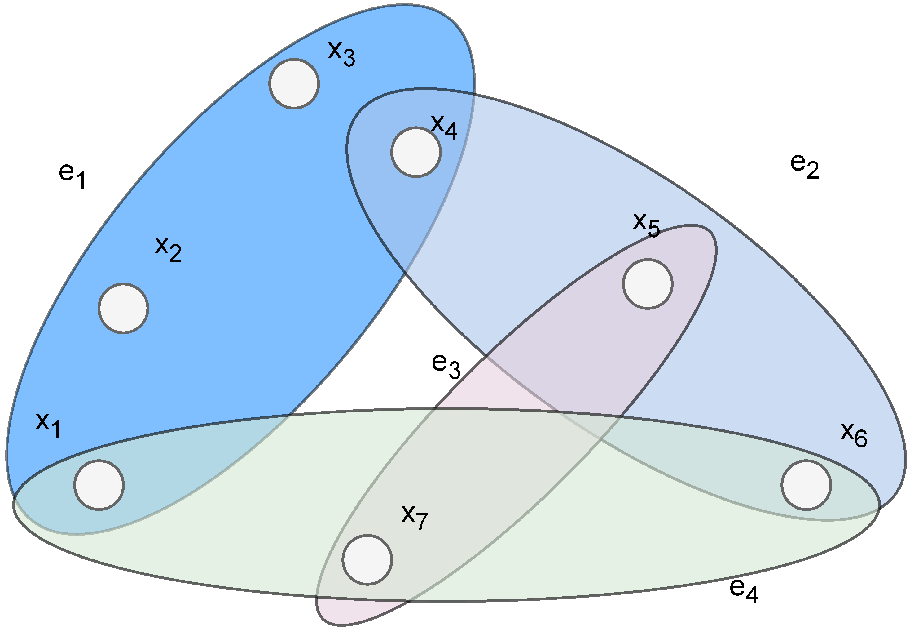
Figure 1. An example of a hypergraph representing seven hypervertices (depicted as V = { x 1 , x 2 , , x 7 } ) and four hyperedges (the ellipses represent hyperedges) E = { e 1 , e 2 , e 3 , e 4 } . With the hypervertices each connected to the hyperedges accordingly { x 1 , x 2 , x 3 , x 4 } e 1 , { x 4 , x 5 , x 6 } e 2 , { x 5 , x 7 } e 3 , { x 1 , x 6 , x 7 } e 4 .
Applmech 06 00074 g001
Figure 2. Hyperedge with hyperarc sets (tail set, head set) marks, one hyperedge E = { e 1 } connecting the four hypervertices V = { x 1 , x 2 , x 3 , x 4 } . The head set e 1 + contains x 1 , x 2 , and the tail set e 1 contains x 3 ,   x 4 .
Applmech 06 00074 g002
Figure 3. (a) Directed hypergraph example with nine hypervertices and three hyperedges (hyperarcs indicate connectivity between edges and nodes), denoted with tail set e i and head set e i + . (b) The same hypergraph represented by its incidence graph (2-factor) representation denoted as a bipartite graph. The hyperarcs are represented as the edges in this graph.
Applmech 06 00074 g003
Figure 4. Screenshot of the hypergraph-editor application, modeling a simple directed hypergraph with one hyperedge connecting two hypervertices, in an incidence graph fashion (bipartite decomposition).
Applmech 06 00074 g004
Figure 5. Crane-like structure modeled following hypergraph notation. The joints denote fixation points and axes of movement. Joint #1 represents a fixed structure, links connected together. Joint #2 represents a crane like fixation, with a prismatic movement axis on the X-axis. Joint #3 represents a revolute joint on Z-axis, rotating the rigid body.
Applmech 06 00074 g005
Figure 6. The process of generating URDF/SDF from the HyMeKo hypergraph-based format by using Large-language models and input validation to check the capability to simulate generated descriptions.
Applmech 06 00074 g006
Figure 7. Definition of a kinematic joint using directed hypergraph approach, where hyperarcs define stress and anchor points of kinematic links.
Applmech 06 00074 g007
Figure 8. Modeling a simple robot (1-joint), with a hyperedge connecting the two kinematic links together through one revolute joint. Notice, that AXIS_Z is a separate element, and also connected to the edge definitions.
Applmech 06 00074 g008
Figure 9. Modeling a SCARA-like robot composed of two joints connecting three kinematic links in a chain-like structure. Notice the AXIS_Z relation to the e i + joints to define 2-dimensional motion, with a rotating axis perpendicular to the working plane.
Applmech 06 00074 g009
Figure 10. Visualization of the SCARA-like robot in the MuJoCo simulator.
Applmech 06 00074 g010
Figure 11. Distribution of generated URDF lengths (histogram with kernel density estimation) produced by ChatGPT using the HyMeKo description of a SCARA-like robot. The histogram shows that the data cannot be well approximated by a single normal distribution. Typical lengths cluster around 252 characters, with most values falling between 220 and 290 characters.
Applmech 06 00074 g011
Figure 12. A single hyperedge connects the spring, damper, and mass element to the fixed chassis through a joint. The road disturbance is modeled as an external force F r o a d , while the spring and damper contribute restoring and dissipative forces. The hypergraph formalism captures the interactions between the components of the quarter-vehicle suspension system.
Applmech 06 00074 g012
Figure 13. (a) Simulink system generated from hypergraph description of the quarter vehicle dynamics model, following system equations Equations (10) and (12), with a step-impulse simulating road obstacle. (b) The simulation result run on road blocks simulated by pulses on a 2 s simulation time with the system’s input impulse.
Applmech 06 00074 g013
Table 1. Physical elements and their hypergraph equivalent concepts.
Physical ElementHypergraph ElementProperty
Rigid body elementHypervertexStatic element, robotic link element
Multi-body constraintHyperedgeDefines constraint of an element
JointHyperedgeDefines a joint of a robotic kinematic structure
Axis definitionHyperarcDefines the axis of movement for the kinematic structure
Joint typeHyperarcDefines the joint type (revolute, prismatic) for the joint
SpringHypervertexDefines the spring element
DampingHypervertexDefines the damping element
MassHypervertexDefines the mass element
Kinematic treeKinematic graphStructures the relationship between physical elements
Table 2. Denavit-Hartenberg aparameters of the generated SCARA robot.
i (Joint Index) θ i (Rotated) d i (Offset) a i (Link Length) α i (Twist Angle)
1 θ 1 0.630.3 π / 2
2 θ 2 0.00.50
Table 3. Simulation parameters of the quarter-vehicle model.
ParameterValue
Simulation time2 s
Input signal typeStep-impulse
Input period time2 s
Input impulse duty cycle5%
Noise typeBand-Limited White Noise
Noise power0.1
Table 4. URDF and MuJoCo XML generation results using ChatGPT 4.1, basic descriptive statistics on character length of each description following the generation of structures modeled in Section 5.1.
Kinematic StructureHyMeKo LengthURDF Mean LengthStandard DeviationMuJoCo-XML Mean LengthStandard Deviation
Simple linkage7116422.679130.856456
SCARA-like robot10125223.14263912923.606723
Table 5. URDF and MuJoCo-XML generation results using ChatGPT 4.1 summarizing error rate, average character reduction on a total of 300 generated samples.
Kinematic StructureSingle LinkageSCARA Linkage
Valid files285245
Character reduction (avg.)—URDF56%50%
Error rate—URDF5%18%
Wilcoxon-value to test shortness 8.4913 × 10 49 2.2547 × 10 36
Valid files225272
Character reduction (avg.)—MuJoCo XML25%21.7%
Error rate—MuJoCo XML25.2%9.3%
Wilcoxon-value to test shortness 6.4470 × 10 29 2.6512 × 10 43
Disclaimer/Publisher’s Note: The statements, opinions and data contained in all publications are solely those of the individual author(s) and contributor(s) and not of MDPI and/or the editor(s). MDPI and/or the editor(s) disclaim responsibility for any injury to people or property resulting from any ideas, methods, instructions or products referred to in the content.