Article

An Analytical Solution for Short Thin-Walled Beams with Monosymmetric Open Sections Subjected to Eccentric Axial Loading

by
Branka Bužančić Primorac
,
Marko Vukasović
*,
Radoslav Pavazza
and
Frane Vlak
Faculty of Electrical Engineering, Mechanical Engineering and Naval Architecture, University of Split, Rudjera Boškovića 32, 21000 Split, Croatia
*
Author to whom correspondence should be addressed.
Appl. Mech. 2025, 6(3), 68; https://doi.org/10.3390/applmech6030068
Submission received: 4 July 2025 / Revised: 18 August 2025 / Accepted: 3 September 2025 / Published: 5 September 2025

Abstract

A simple analytic procedure for the linear static analysis of short thin-walled beams with monosymmetric open cross-sections subjected to eccentric axial loading is presented. Under eccentric compressive loading, the beam is subjected to compression/extension, to torsion with influence of shear with respect to the principal pole and to bending with influence of shear in two principal planes. The approximate closed-form solutions for displacements consist of the general Vlasov’s solutions and additional displacements due to shear according to the theory of torsion with the influence of shear, as well as the theory of bending with the influence of shear. The internal forces and displacements for beams clamped at one end and simply supported on the other end, where eccentric loading is acting, are calculated using the method of initial parameters. The shear coefficients for the monosymmetric cross-sections introduced in these equations are provided. Solutions for normal stress and total displacements according to Vlasov’s general thin-walled beam theory, and those obtained with the proposed method taking shear influence into account, are compared with shell finite element solutions analyzing isotropic and orthotropic I-section beams. According to the results for normal stress relative differences, and Euclidean norm for displacements, it has been demonstrated that shear effects must be accounted for in the analysis of such structural problems.

1. Introduction

Due to the advantages like high strength-to-weight and stiffness-to-weight ratio, thin-walled beams with open, closed, and closed-open sections are ideal structural elements often used in different engineering fields as stand-alone carrying elements or as a part of the structures [1,2]. The short beams subjected to eccentric axial loading can be found in civil engineering [3,4] or ship structures as supporting structural elements, subjected to eccentric compression load-like columns, pillars, etc. [5]. Under eccentric compression loading, the structural elements are subjected to tension/compression, torsion and, at the same time, to bending in two principal planes that are influenced by material properties, cross-section geometry, and boundary conditions [6]. Vlasov’s general thin-walled beam theory represents an efficient instrument for the analysis of thin-walled beams [7]. Based on the assumptions that the shape of the cross-section does not change in its own plane during beam deformation and that the beams are long enough that the shear deformation in the beam’s mid-surface can be neglected, this theory provides simple analytical solutions for the stresses and displacements of the beams subjected to the axial loads with the magnitude below the critical buckling load. On the other hand, the structural behavior of axially loaded thin-walled beams with low length-to-height ratios is affected by the shear influence, making Vlasov’s theory unsuitable for the analysis. The bending and torsion of thin-walled beams under general transverse loading, with and without shear effects, have been extensively studied [8,9,10,11,12,13,14,15,16,17,18,19,20].
In the literature, axially loaded thin-walled beams with open sections are mostly considered within stability analysis, where the prediction of critical buckling loads and corresponding modes is the main objective. Different theoretical, numerical, and experimental studies related to flexural-torsional buckling of thin-walled isotropic [7,21,22,23] and composite beams [24,25,26,27,28] have been carried out. Another area of interest includes distortion by buckling [29,30,31]. Axially loaded thin-walled beams have also been included in flexural–torsional vibration analysis, where the determination of natural frequencies and mode shapes is of primary interest [32,33,34,35]. Regarding the eccentric loads, it is shown that these loads amplify localized buckling in thin-walled sections, particularly in open cross-sections like C-channels or Z-profiles [36,37]. The load eccentricity shifts the neutral axis, inducing uneven stress distribution and reducing thin-walled beam capacity by 20–40% in CFRP channels [35] and up to three times in steel I-sections compared to centric loading [35,36].
Although a substantial number of published papers are devoted to axially loaded thin-walled beams, according to the author’s knowledge, there are not many papers (if any) dealing exclusively analytically with extremely short thin-walled beams subjected to eccentrically applied axial loads. The influence of shear on stress and displacement distribution has not been adequately investigated in cases when the magnitude of applied load is below the critical buckling point. On the contrary, some examples where the axial load of these members is included in the development of 1D and 3D numerical models can be found in the literature [38].
The theory used in this paper is based on the general Vlasov’s theory of thin-walled beams of open cross-section [7], as well as Timoshenko’s beam bending theory [38,39,40], which takes into account the shear effect for short beams subjected to bending only. The theory of torsion with the influence of shear, as well as the theory of bending with the influence of shear [11,12,13,14], are used in this paper in the analysis of short thin-walled monosymmetric I-section beams (with z-axis of symmetry) that are subjected to eccentrically applied compressive loading. According to the cited theories, expressions for additional displacements due to shear of the thin-walled beams with monosymmetric open cross-sections are given, containing the following five different shear factors: κyy, κzz, κωω, κxz, and κ = κωy. In previous authors’ papers [41,42] dealing with eccentrically compressed bisymmetric I-section beams, it is shown that only three shear factors (κyy, κzz, and κωω,) exist due to double symmetry. Therefore, as the novelty in this paper, new shear factors are introduced: κxz as the shear factor contributing additional tension/compression due to shear in bending in the principal xz plane, κ used to define additional bending in the principal xy plane due to shear in torsion, and κωy defining additional torsion due to shear in bending. Shear factors κ and κωy take into account coupling due to shear between torsion and bending (in a plane perpendicular to the plane of symmetry) that can also be highlighted as a novel contribution compared to the papers dealing with bisymmetric cross-sections. Also, the analytical procedure shown in Section 2 of the paper is applicable to eccentrically compressed thin-walled clamped-hinged beams of any monosymmetric cross-section with z-axis of symmetry, and is not restricted to the I-sections only. For the other cross-sections, their geometrical properties, including shear factors, must be determined and used in the calculation. Isotropic and orthotropic beams with monosymmetric sections and a slenderness ratio below the limit slenderness to avoid buckling are considered. St. Venant’s pure moment of torsion is neglected in torsion analysis. This is the case where a full analogy between bending and torsion exists [11]. The method of initial parameters [7,12,13,14,43] is used to define internal force components and displacements for the analyzed clamped-hinged beams. Based on shear factors, new shear coefficients k a u , k a v α , and k a α v are presented. It is shown that these coefficients vanish in the analysis of beams with two axes of symmetry [41,42]. Normal and shear stresses, as well as the displacements, are compared with Vlasov’s solution and the finite element method utilizing shell elements [44].

2. Analytic Solutions for Stresses and Displacements of Beams Subjected to Compression/Tension, Bending, and Torsion with Influence of Shear

2.1. Assumptions and Constraints

The following assumptions are adopted in this analysis:
  • The material is linear isotropic/orthotropic elastic;
  • The shape of the cross-section is preserved during the beam deformations;
  • Normal stresses in the beam walls are negligible, except for longitudinal normal stresses, which are uniformly distributed across the cross-section thickness;
  • Shear stresses are negligible, except those acting tangentially along the midline of the cross-section. It is assumed that these stresses are also uniformly distributed across the cross-section thickness.
The presented assumptions align with Vlasov’s general thin-walled beam theory [7], except for the assumption that shear strains in the mid-surface are negligible. In the analysis presented in this paper, the shear strain in the beam’s middle surface is taken into account.
The analysis is valid for the following constraints:
  • The beam is a thin-walled structure with the following ratios: d/t ≥ 40, l/d ≤ 5, where t is the wall thickness, d is the length of the cross-section part (between rigid joints or between joint and free edge), and l is the beam length;
  • The cross-section of the beam must be reinforced with appropriate diaphragms to prevent the distortion of the section;
  • The applied load is below the critical buckling load.
St. Venant’s moment of torsion is ignored according to the first constraint. This component is small for the given ratios, and it can be neglected with respect to the warping component Mω, i.e., MP = Mω, where MP is the total moment of torsion with respect to the cross-section principal pole (shear center) [11].

2.2. Stresses and Internal Force Components of Axially Loaded Beams

For thin-walled beam-columns with open cross-sections under eccentrically applied axial loads, the normal and shear stress distributions are given by the following [7,11,12,13,14]:
σ x = N A + M y I y z M z I z y + B I ω ω , τ x ξ = 1 t Q y S z * I z + Q z S y * I y + M ω S ω * I ω ,
where N = N(x) denote the axial force, My = My(x) and Mz = Mz(x) are the bending moments about the y- and z-axes, B = B(x) is the bimoment, Qy = Qy(x) and Qz = Qz(x) are the transverse shear forces, and Mω = Mω(x) is the warping moment, and the cross-section properties are as follows:
A = A d A , I y = A z 2 d A , I z = A y 2 d A , I ω = A ω 2 d A , S y * = s * z d A * , S z * = s * y d A * , S ω * = s * ω d A * , d A = t d s , d A * = t d s * .
As shown in Figure 1, the rectangular coordinates y = y(s) and z = z(s) are defined with respect to the principal rectangular axes Cy and Cz, ω s = 0 s h P d s is the sectorial coordinate with respect to the principal pole P (shear center), hP = hP(s) is the distance from the pole P to the tangent ξ on the cross-section middle line, s is the curvilinear coordinate from the starting point M0, and s* is the curvilinear coordinate from the free edge where the shear stress is zero, i.e., for s* = 0, τ = 0.
Internal forces in terms of displacements can be written according to stress–internal force relations as follows [7,12,13]:
N = E L A d u a x d x M y = E L I y d 2 w b d x 3 M z = E L I z d 2 v b d x 3 B = E L I ω d 2 α t d x 3 Q y = E L I z d 3 v b d x 3 Q z = E L I y d 3 w b d x 3 M ω = E L I ω d 3 α t d x 3
where uax = uax(x), wb = wb(x) and vb = vb(x) represent the displacements of the cross-sections, treated as a plane sections in the x-, y- and z-directions, respectively, αt = αt(x) is the angular displacement of the cross-section as a plane section with respect to the pole P, and EL is Young’s modulus of elasticity in the longitudinal direction.
According to the theory of bending and torsion with the influence of shear [11,12,13,14], additional displacements due to shear of the thin-walled beams with monosymmetric cross-sections (with z-axis of symmetry) can be written as
u a = κ x z G L T A L a Q z , v a = κ y y G L T A M z 0 M z + κ y ω G L T W P B B 0 , w a = κ z z G L T A M y M y 0 , α a = κ ω y G L T W P M z 0 M z + κ ω ω G L T I P B B 0
where GLT is the in-plane shear modulus, La is the arbitrary length of the cross-section middle line (between joints or between joint and free end), I P = A h P 2 d A and W P = I P / h 0 with h0 shown in Figure 1. Also, My0 = My (x = 0), Mz0 = Mz (x = 0), and B0 = B (x = 0). As evident from Equation (4), the beam is additionally subjected to tension/compression due to shear (shear factor κxz), to bending in the principal x-y plane due to shear (shear factor κyy) and due to shear in torsion (shear factor κ), to bending in the principal x-z plane due to shear (shear factor κzz) and to torsion due to shear (shear factor κωω), and due to shear in bending (shear factor κωy).
According to [11,12,13,14], the shear factors are defined as follows:
κ x z = 1 I y L a A A * S y * t 2 d A , κ y y = A I z 2 A S z * t 2 d A , κ z z = A I y 2 A S y * t 2 d A , κ y ω = κ ω y = W P I y I ω A S z * S ω * t 2 d A , κ ω ω = I P I ω 2 A S ω * t 2 d A
The total displacements of the beam centroid line can now be obtained using the solutions of Equation (3) with Equation (4) as
u = u a x + u a , v = v b + v a , w = w b + w a , α = α t + α a
while the displacements of an arbitrary point S on the cross-section contour correspond to rigid-body displacements of the entire cross-section contour, which are expressed as
u S = u + β z S γ y S + α ω S , v S = v ( z S a z ) α , w S = w + y S · α
where az is the rectangular z-coordinate of the principal P. For the monosymmetric I section in Figure 1, it amounts to az = h0h1C.
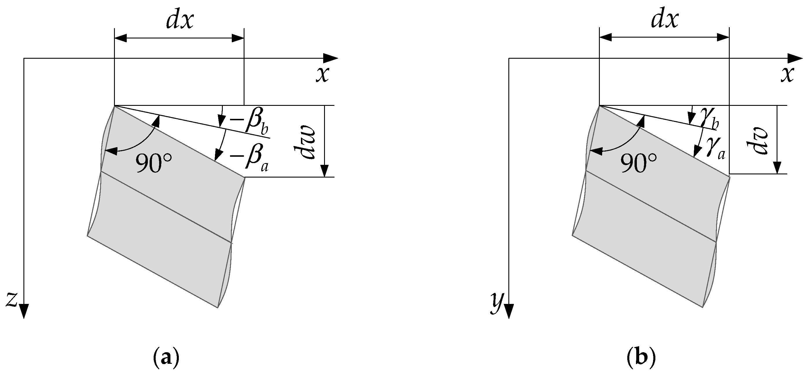
The total angular displacements of the cross-section, treated as a plane section, about the y- and z-axis, respectively, are presented in Figure 2 and calculated as
β = β b + β a , γ = γ b + γ a
where β b = d w b / d x represents the angular displacement of the cross-section, treated as a plane section about the y-axis due to bending; β a = d w a / d x represents the additional displacement due to shear in the Cxz plane; γ b = d v b / d x represents the angular displacement of the cross-section, treated as a plane section about the z-axis due to bending, and γ a = d v a / d x represents the additional displacement due to shear in the Cxy plane.

2.3. The Method of Initial Parameters

The expressions for the internal force components and displacements can be easily obtained using the method of initial parameters. The problems analyzed in this paper result in four equation systems that can be generally expressed in the matrix form as
v = K v 0 + v c
where the state vector for axial loads reads as follows
v = N u T
while, for bending in the xz plane, it reads
v = Q z M y β b w T .
For the bending in xy plane, the state vector is
v = Q y M z γ b v T
Finally, the state vector for torsion reads
v = M ω B ϑ t α T
where ϑ t = d α t / d x is the relative angle of torsion with respect to the principal pole P.
The initial state vectors v0 in Equation (9) are defined for all load cases as v0 = v (x = 0). With the introduction of shear coefficients
k a u = κ x z E L G L T , k a w = κ z z E L I y G L T A l 2 , k a v = κ y y E L I z G L T A l 2 , k a v α = κ y ω E L I z G L T W P l , k a α v = κ ω y E L I ω G L T W P l 3 , k a α = κ ω ω E L I ω G L T I P l 2
the field matrices K for bending in the xz and xy plane, as well as for torsion, are defined as follows
K = 1 0 0 0 x 1 0 0 x 2 2 E L I y , z , ω x E L I y , z , ω 1 0 1 E L I y , z , ω x 3 6 k a w , v , α l 2 x x 2 2 E L I y , z , ω x 1
respectively. For the axial load, the field matrix is
K = 1 0 x E L A 1
while the coupling vector for the beam with a monosymmetric cross-section is
v c = 0 k a u h E L A Q z 0 T
where La = h.
For bending in the xz plane, this vector is vc = 0, while for bending in the xy plane, it reads
v c = 0 0 0 k a v α l 2 x E L I z M ω 0 T .
Finally, the coupling vector for torsion is
v c = 0 0 0 k a α v l 3 x E L I ω Q y 0 T .
As can be seen from Equations (17)–(19), the “coupling” terms do not affect the w displacement due to the analyzed monosymmetric cross-section shape.

Clamped-Hinged Beam Under Eccentric Axial Load

The beam that is clamped at one end (x = 0) and simply supported at the other end (x = l) is analyzed in this paper. In that case, and based on Equations (10)–(13), the initial state vectors read
v 0 = N 0 0 T , v 0 = Q z 0 M y 0 0 0 T , v 0 = Q y 0 M z 0 0 0 T , v 0 = M ω 0 B 0 0 0 T ,
for axial loading, bending in the Cxz and Cxy planes, and torsion, respectively. The unknown initial parameters in Equation (20) are determined using boundary conditions for the simply supported end of the beam that read
v ( x = l ) = N ( l ) u ( l ) T , v ( x = l ) = Q z ( l ) M y ( l ) β b ( l ) 0 T , v ( x = l ) = Q y ( l ) M z ( l ) γ b ( l ) 0 T , v ( x = l ) = M ω ( l ) B ( l ) ϑ t ( l ) 0 T
The unknown initial parameters are calculated by assuming that the beam is loaded with a compressive axial force (Fx = −F) in the arbitrary point K of the cross-section at the beam end (x = l). In that case, and according to Equation (21), internal force components can be calculated as follows:
N ( l ) = F , M y ( l ) = F · z K , M z ( l ) = F · y K , B ( l ) = F · ω K ,
where yK, zK, and ωK are principal rectangular and sectorial coordinates of the point K.
Using Equations (20)–(22), the equation systems (9) lead to unknown initial parameter values
N 0 = N ( l ) , Q y 0 = 3 2 l 2 3 k a v α B ( l ) + l ( 1 + 3 k a α ) M z ( l ) 9 k a v α k a α v ( 1 + 3 k a v ) ( 1 + 3 k a α ) , Q z 0 = 3 M y ( l ) 2 l 1 1 + 3 k a w , M ω 0 = 3 2 l ( 1 + 3 k a v ) B ( l ) + 3 l k a α v M z ( l ) 9 k a α v k a v α ( 1 + 3 k a v ) ( 1 + 3 k a α ) , M y 0 = M y ( l ) 2 1 6 k a w 1 + 3 k a w , M z 0 = 9 k a v B ( l ) + l M z ( l ) 18 k a v α k a α v + ( 1 + 3 k a α ) ( 1 6 k a v ) 2 l 9 k a v α k a α v ( 1 + 3 k a v ) ( 1 + 3 k a α ) , B 0 = 9 k a α v l M z ( l ) + 18 k a α v k a v α + ( 1 + 3 k a v ) ( 1 6 k a α ) B ( l ) 2 9 k a v α k a α v ( 1 + 3 k a v ) ( 1 + 3 k a α )
For cross-sections with two axes of symmetry, these initial parameters reduce to the simple forms expressed in [41,42] since k a v α = k a α v = k a u = 0.

3. Illustrative Examples

In order to validate the presented analytical method, several types of monosymmetric cross-sections are preliminarily analyzed and compared with the finite element solutions. As expected, it showed that numerical solutions for thin-walled U and lipped channel sections without diaphragms do not comply with the second assumption given in Section 2.1, i.e., the cross-section distortion appeared in these analyses. So, to avoid additional modelling of the large number of diaphragms with the intention to maintain the assumption of the rigid cross-section contours, it is decided to analyze solely a monosymmetric I section in detail since its distortion is practically negligible.
The I section height, h = 600 mm, as presented in Figure 1, is adopted and kept constant for all the analyses performed. According to the first constraint (Section 2.1), the following ratios h/t0 = b1/t1 = b2/t2 = 40 are also adopted as constants. The analyses are performed for the cross-section geometries with b1/h = 1, b1/h = 2, b1/b2 = 2, and b1/b2 = 4. The corresponding geometrical properties of all analyzed cross-sections are calculated according to the expressions given in Appendix A.
The carbon steel with E = 210 GPa and ν = 0.3 (G = 80.769 GPa) is used as an isotropic linear elastic material in the presented solutions. Glass-reinforced laminate is modeled as an orthotropic linear elastic material with the following properties: longitudinal modulus EL = 23 GPa, transverse modulus ET = 8.5 GPa, Poisson’s ratios νLT = 0.23 and (νTL = 0.09), and in-plane shear modulus GLT = 3 GPa [44]. Here, L and T denote the longitudinal and transverse material axes, respectively. Assuming isotropic behavior in the wall section’s own TW plane, and using νTW = 0.25 [41], where W is the direction normal to the laminate face, the transverse shear modulus required for finite element analysis is calculated as GTW = 3.6 GPa.
Distributed line load acting along the half of the cross-section upper flange, according to Figure 3a, is used in all the analyses to avoid unnecessary difficulties related to the application of the concentrated load in the shell finite element analysis. The adopted value of q = 100 N/mm can be easily scaled to any value, ensuring linear elastic behavior of the analyzed beam. In this case, the values F = q·b1/2, yK = b1/4, zK = −h1C, and ωK = b1/4·h0 are used for the calculation of the internal forces in Equation (22).
The numerical solutions are obtained using software package ADINA 23.00.01 [44] that is based on the finite element method (FEM). The 3D model of the beam’s middle surfaces, shown in Figure 3b, is discretized using 4-node MITC4 shell finite elements with a uniform mesh size. The mesh is configured to comply with the software constraint of a maximum of 10,000 nodes. The MITC4 shell element is formulated using Timoshenko beam theory, assuming that material particles originally lying on a straight line “normal” to the middle surface of the structure remain on that straight line during the deformations, and on the Reissner/Mindlin plate theory assumption that the stress in the direction normal to the middle surface of the structure is zero [44]. The linear elastic structural analysis is performed under the assumption of small strains and displacements. The default mesh size of 40 mm is used for all simulations, and based on the beam length, the number of elements varies between 1840 and 4256. Due to the software limitation on the number of nodes, the convergence test is not performed. Boundary conditions applied to the beam are illustrated in Figure 2b. The symbol B denotes the simply supported end, while C represents the clamped end. Also, the symbols U1, U2, and U3 denote translational degrees of freedom (DOF) in the direction of X, Y, and Z axes, while the symbols θ1, θ2, and θ3 represent rotational DOF about the X, Y, and Z axes, respectively.
At the simply supported end of the beam, X-translation (U1) and Y- and Z-rotations (θ2 and θ3) are free, while Y- and Z-translations (U2 and U3) and X-rotation (θ1) are fixed, ensuring compatibility with a roller support that restrains torsional rotation. Although the presented analytical model results in additional angular displacements βa and γa at fixed support, this support is modeled in the finite element analysis in a standard way, i.e., by restricting all degrees of freedom. Lines A, B, C, D, E, F, and G in Figure 3b are used to compare numerical and analytical solutions.
Numerical solutions for stresses and displacements obtained using the finite element method (FEM) are compared with analytical results derived from two approaches, the theory of bending and torsion of thin-walled beams with shear influence (TBTS) and the general Vlasov’s theory of thin-walled beams of open cross-section, which uses the same governing equations as TBTS, but neglects shear effects by setting the value of shear factors κxz, κyy, κzz, κωy, and κωω equal to zero in Equations (4) and (14). This comparison enables evaluation of the shear influence on the structural response of thin-walled beams.
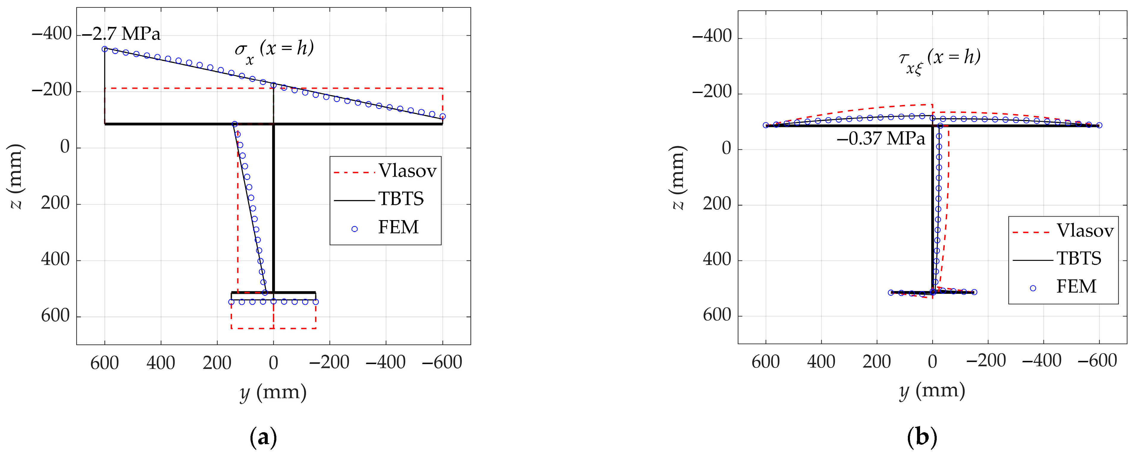
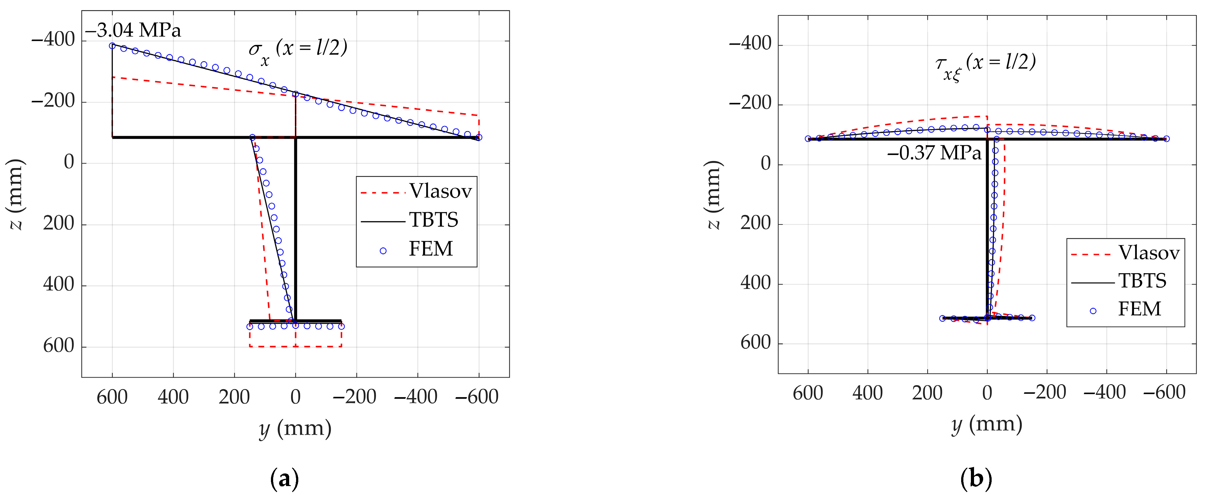
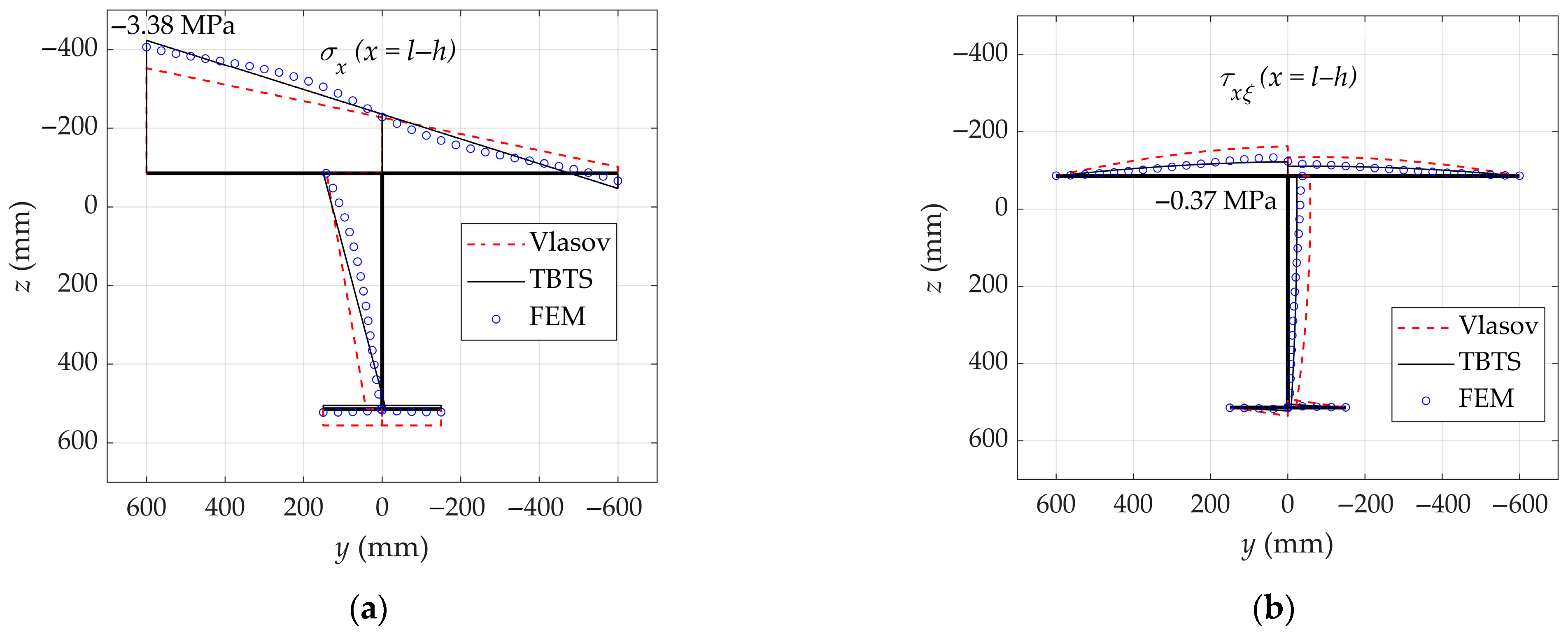
The distributions of the longitudinal normal stress σx and shear stress τ using Equation (1) for l/h = 3, b1/h = 2 and b1/b2 = 4, obtained by TBTS, Vlasov and FEM along cross-section contour at the sections x = h, l/2, l − h (to avoid stress concentrations in the vicinity of the supports), for orthotropic beam, are presented in Figure 4, Figure 5 and Figure 6.
From the results shown in Figure 4, Figure 5 and Figure 6, it is evident that the TBTS solution aligns significantly better with the FEM results than the Vlasov solution. This conclusion applies to all cross-sections along the beam, except near the ends, where the influence of the supports is predominant. The constant normal stress distribution along the section contour for Vlasov’s solution in Figure 4a is easy to justify. Namely, for l/h = 3 and x = h = l/3, internal force components My, Mz, and B, calculated using Equation (9) with reference to Equation (23), where shear influence is neglected, vanish. So, the normal stress arises only from the axial load, resulting in a constant distribution along the contour. As expected, the normal stresses are higher than the shear stresses, but in some situations, the influence of these stresses cannot be neglected. Also, it must be emphasized that shear stresses are constant along the beam for these boundary conditions and this load. Similar distributions for both stresses are obtained for l/h = 5. To evaluate the accuracy of analytical stress predictions, normal stresses σx obtained using the TBTS and general Vlasov’s theory are compared to FEM results at the cross-section x = l/2, thereby minimizing the influence of the supports and applied loading. Relative differences are calculated according to Equation (24) for five reference lines, A, B, C, D, and E, located on the upper flange of the beam.
σ ˜ x TBTS , VL = σ x TBTS , VL σ x FEM σ x FEM · 100
Table 1 and Table 2 present results for various dimensional ratios, considering beams with isotropic and orthotropic material properties.
From these tables, it is easy to notice that analytical solutions for normal stress obtained by taking shear influence into account (TBTS) are significantly closer to numerical (FEM) solutions compared to corresponding Vlasov’s solutions. For lines A, B, C, and D, the relative differences of TBTS solutions are below 8% for all analyzed problems. More precisely, the relative errors for these lines of isotropic beams are smaller or very close to 1% which is a significant improvement over Vlasov’s solutions. Slightly larger differences can be observed for line E, particularly for very short beams (l/h = 3), but these solutions are still considerably better than the Vlasov ones.
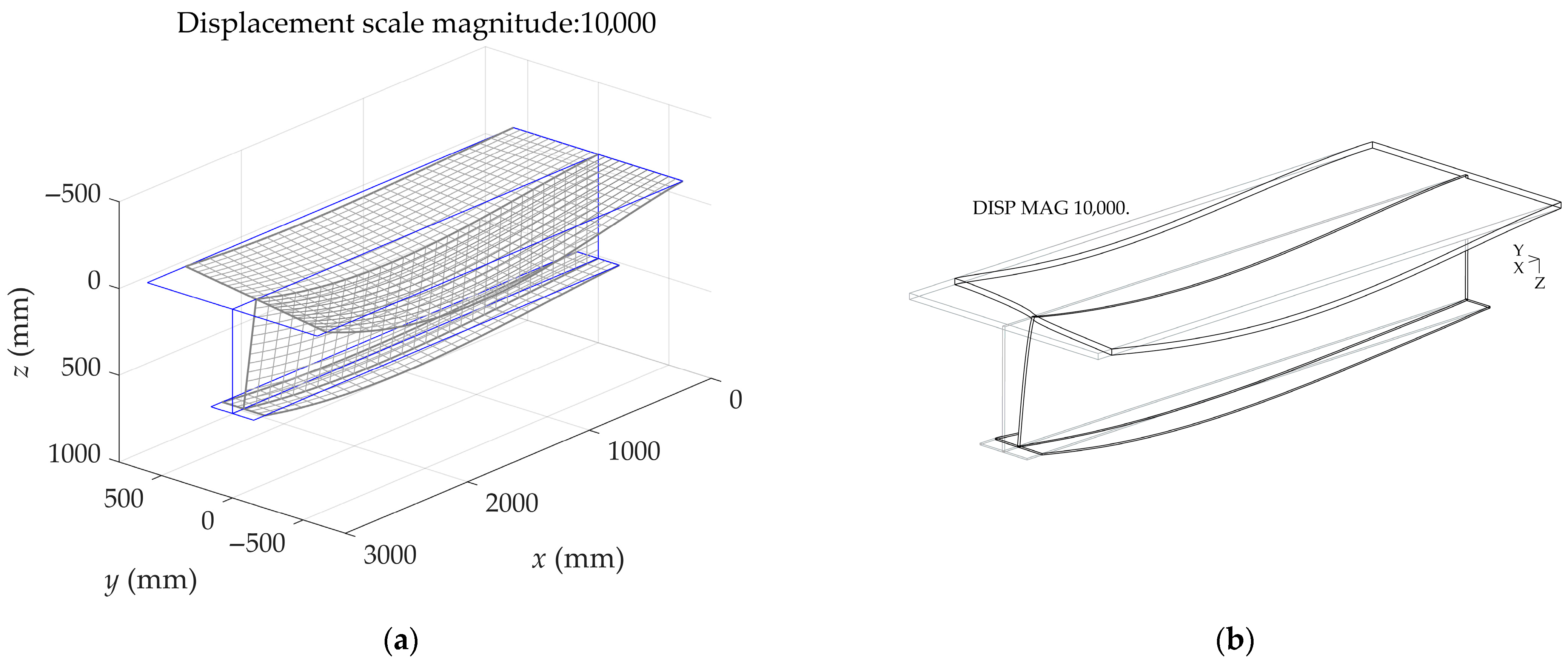
Undeformed and deformed configurations for an isotropic beam with l/h = 5, b1/h = 2, and b1/b2 = 4 obtained by TBTS and FEM are shown in Figure 7 with the same displacement scale magnitude. The similarity between the analytical and numerical solutions is clearly noticeable. It is important to emphasize that the configuration shown in Figure 7a was generated using MATLAB R2022b [45], not FEM. The displacements were computed analytically based on Equations (3)–(23) for an arbitrarily defined grid of points.
To give better insight into displacement solutions, total displacements are calculated according to the following:
δ = u i + v j + w k
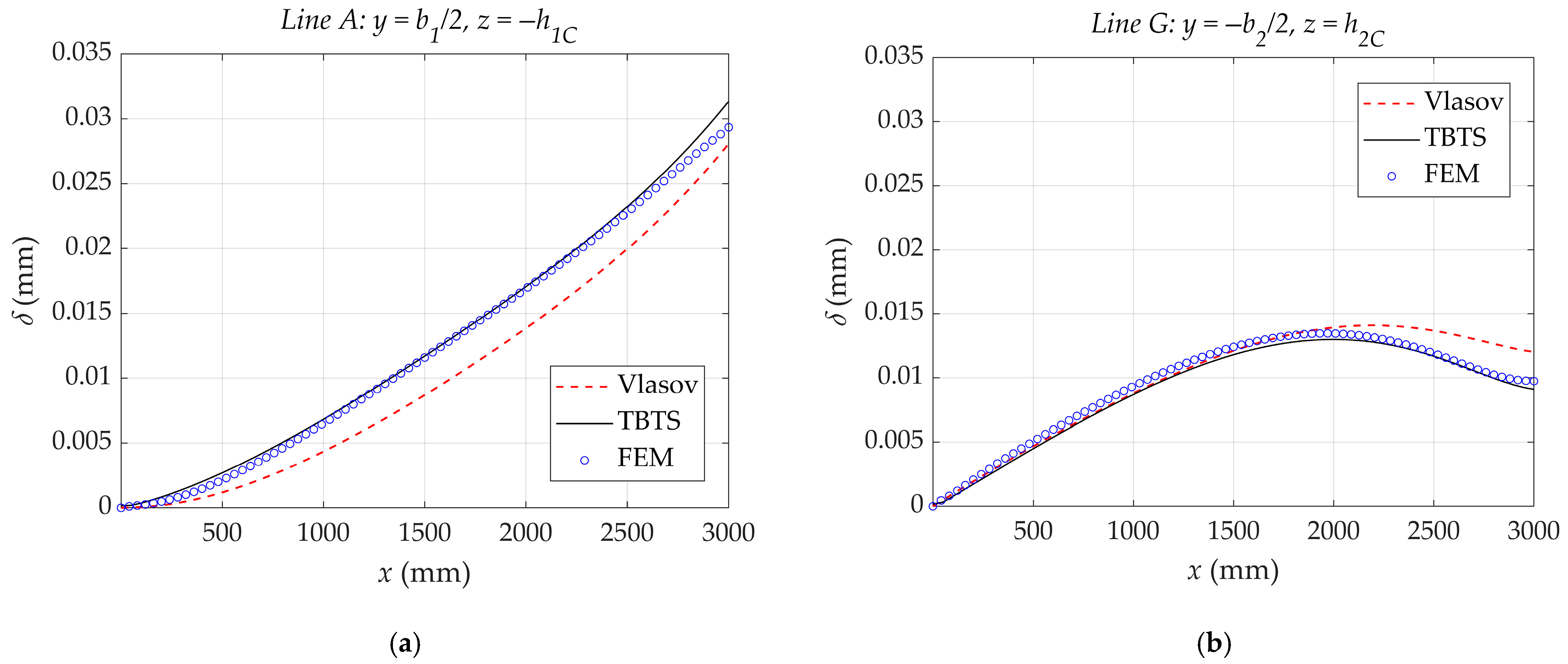
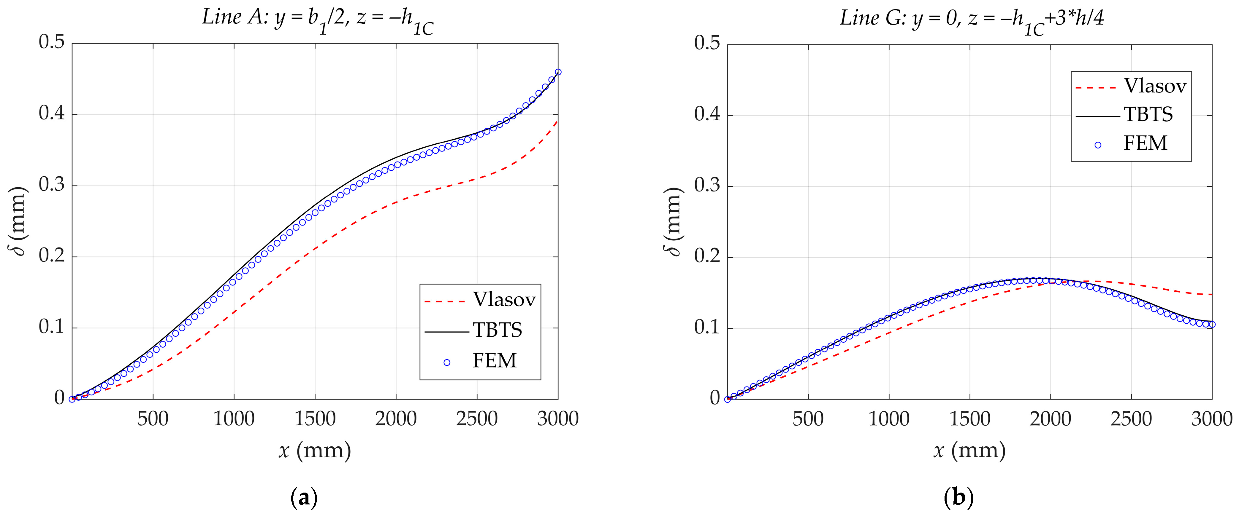
where u, v, and w are displacements calculated by Equation (7) while i , j , k are unit vectors in the x, y, and z directions. Figure 8 and Figure 9 show distributions of total displacements along lines A and G of beams for arbitrarily chosen geometrical and material properties. These lines are selected to show different curve shapes of displacement distributions that can appear in the analysis. Similar distributions are obtained for the other beam properties.
To quantify the similarity between analytical and numerical displacement solutions, total displacements δ obtained using the TBTS and the general Vlasov’s theory are compared to FEM results using the Euclidean norm as a similarity measure, which is defined as:
δ ˜ TBTS , VL = i = 1 n δ i TBTS , VL δ i FEM 2
As the Euclidean norm approaches zero, the similarity between solutions increases. These calculations are performed for reference lines located on the beam upper flange (lines A, C, and E), on the beam web (lines C and F), and on the beam lower flange (lines F and G). Table 3 and Table 4 present results for various dimensional ratios, considering beams with isotropic and orthotropic material properties.
By comparing the results, it is evident that the displacement solutions obtained using the TBTS closely match those from the FEM analysis, which confirms the reliability of TBTS in the displacement calculation of thin-walled beams when shear effects are considered. According to Table 3 and Table 4, the Euclidean norm for TBTS is a few times smaller compared to the Vlasov solution. It is especially highlighted for line A of orthotropic material, where the TBTS norm is 10 times smaller than the Vlasov one. Again, as for the normal stress solutions, a small discrepancy of this conclusion arises for line E, especially for the ratio b1/h = 2, Table 3, for beams with isotropic and orthotropic material properties. Due to a lack of space, the results of Euclidean norms for 13 different longitudinal beam lines are not presented in this paper, but it must be emphasized that results for the line E are the only exception regarding similarity between TBTS and FEM compared to the Vlasov and FEM solutions.

4. Conclusions

Thin-walled beams with open cross-sections are frequently used as structural elements in many engineering fields. To the best of the authors’ knowledge, the solutions for the linear static analysis of the short thin-walled beams with monosymmetric open sections, clamped at one end and simply supported at the other end where an eccentric axial load is acting, are not provided yet. For larger beams, Vlasov’s general solutions are applicable. Due to the eccentric axial loading, the beam experiences additional bending in both principal planes and torsion with respect to the principal pole. Therefore, a closed-form approximate analytical solution for both stresses and displacements is presented in this paper. The solutions are derived using Vlasov’s general theory of bending and torsion of thin-walled beams [7] and the theory of bending and torsion with the influence of shear [11,12,13,14].
It is assumed that the St. Venant component of torsion can be neglected in the analysis of short thin-walled beams [11], which is justified by analyzing the results of performed simulations. Also, the assumption of unaltered cross-section contours is important, and the application of the proposed method to monosymmetric U and lipped channel sections, without introducing diaphragms along the beam that will preserve cross-section shape, is not recommended.
The solutions for isotropic and orthotropic monosymmetric I-section thin-walled beams are obtained using the method of initial parameters. Using newly introduced shear coefficients in these equation systems, the initial internal force and displacement components are provided and used to calculate longitudinal normal and contour shear stresses and displacements. The solutions calculated using the proposed method and Vlasov solutions, obtained using the same expressions but neglecting the shear coefficients, are compared with numerical solutions obtained using the finite element method (FEM). Regarding the normal stress solutions at the beam upper flange at a distance equal to the beam height from the clamped end, it is shown that relative stress differences for the presented method are significantly closer to FEM solutions than Vlasov solutions for both isotropic and orthotropic beams, and for all analyzed geometrical properties. Also, by taking the Euclidean norm as a similarity measure for comparison of the total displacement distributions along the beam, it is shown that TBTS solutions match FEM displacements better than Vlasov ones. These results justify the application of the presented procedure for these types of problems for both stresses and displacements simultaneously.
This paper is a continuation of the authors’ previous work related to the analysis of thin-walled beams subjected to eccentric axial loads [41,42], where only cross-sections with two axes of symmetry were analyzed. For future work, the authors intend to further extend the analyses to thin-walled beams with arbitrary cross-sections.

Author Contributions

Conceptualisation, R.P. and F.V.; methodology, B.B.P. and M.V.; software, B.B.P. and F.V.; validation, R.P. and F.V.; formal analysis, M.V. and B.B.P.; investigation, M.V.; resources, M.V., B.B.P. and F.V.; data curation, B.B.P. and F.V.; writing—original draft preparation, M.V. and B.B.P.; writing—review and editing, R.P. and F.V.; visualisation, B.B.P. and F.V.; supervision, R.P. and F.V.; project administration; funding acquisition; All authors have read and agreed to the published version of the manuscript.

Funding

This research received no external funding.

Institutional Review Board Statement

Not applicable.

Informed Consent Statement

Not applicable.

Data Availability Statement

The original contributions presented in this study are included in the article material. Further inquiries can be directed to the corresponding author(s).

Conflicts of Interest

The authors declare no conflicts of interest.

Abbreviations

The following abbreviations are used in this manuscript:
FEMFinite element method
TBTSTheory of bending and torsion with the influence of shear
VLGeneral Vlasov’s theory

Appendix A

Monosymmetric I Section—Cross-Section Properties

A 1 = b 1 t 1 , A 2 = b 2 t 2 , A 0 = h t 0 , λ = A 2 A 1 , ψ = A 0 A 1 , μ = h 2 C h 1 C , η = b 2 b 1 , φ = h 1 C h , ρ = b 1 h , L a = h , h 1 C = h 2 λ + ψ 2 1 + λ + ψ , h 2 C = h 2 + ψ 2 1 + λ + ψ , h P = h λ η 2 1 + λ η 2 ,
A = A 1 1 + λ + ψ , I y = A 1 h 2 12 λ + ψ 4 + ψ + 4 λ 12 1 + λ + ψ , I z = A 1 h 2 ρ 2 1 + λ η 2 12 , I ω = A 1 h 4 λ η 2 ρ 2 12 1 + λ η 2 , I P = A 1 h 2 λ 1 + λ η 4 1 + λ η 2 2 , I t = 1 3 A 1 t 1 2 η 2 + λ 3 + η 2 ψ 3 ρ 2 η 2 , W P = I P h 0 = A 1 h 1 + λ η 4 η 2 1 + λ η 2 , κ x y = 0 , κ x z = φ 1 + λ + ψ 24 φ 1 λ 2 μ 2 + 2 ψ ρ 2 1 λ μ η 2 + 20 ψ φ 2 1 λ μ 3 + 5 ψ 2 φ 3 1 μ 4 2 ψ 12 λ + ψ 4 + ψ + 4 λ , κ y z = κ z y = 0 , κ y y = 6 1 + λ + ψ 1 + λ η 4 5 1 + λ η 2 2 , κ z z = φ 2 1 + λ + ψ 3 φ ψ 1 + λ 2 μ 3 + 2 3 φ 2 1 + λ μ 4 + 2 15 ψ φ 3 1 + μ 5 + 1 12 φ 2 1 + λ μ 2 η 2 λ + 1 3 ψ 1 + λ + 1 4 ψ , κ ω y = 6 1 η 2 1 + λ η 4 5 η 2 1 + λ η 2 2 , κ ω z = 0 , κ ω ω = 6 1 + λ 1 + λ η 4 5 1 + λ η 2 2 .

References

  1. Kim, Y.Y.; Jang, G.W.; Choi, S. Analysis of Thin-Walled Beams; Springer: Singapore, 2023. [Google Scholar] [CrossRef]
  2. Basaglia, C.; Camotim, D. Generalized Beam Theory: Moving from Isolated Members to Structural Systems—A state-of-the-art review on GBT applications in thin-walled steel structures. In Proceedings of the Annual Stability Conference Structural Stability Research Council (SSRC 2021), Louisville, KY, USA, 13–16 April 2021; pp. 87–109. [Google Scholar]
  3. Lee, C.-H.; Kang, T.H.-K.; Kim, S.-Y.; Kang, K. Strain compatibility method for the design of short rectangular concrete-filled tube columns under eccentric axial loads. Constr. Build. Mater. 2016, 121, 143–153. [Google Scholar] [CrossRef]
  4. Shakouri Mahmoudabadi, N.; Bahrami, A.; Saghir, S.; Ahmad, A.; Iqbal, M.; Elchalakani, M.; Özkılıç, Y.O. Effects of eccentric loading on performance of concrete columns reinforced with glass fiber-reinforced polymer bars. Sci. Rep. 2024, 14, 1890. [Google Scholar] [CrossRef]
  5. Parunov, J.; Garbatov, Y. Ship Structures. J. Mar. Sci. Eng. 2022, 10, 374. [Google Scholar] [CrossRef]
  6. Patuelli, C.; Cestino, E.; Frulla, G. A Beam Finite Element for Static and Dynamic Analysis of Composite and Stiffened Structures with Bending-Torsion Coupling. Aerospace 2023, 10, 142. [Google Scholar] [CrossRef]
  7. Vlasov, V.Z. Thin-Walled Elastic Beams; Israel Program for Scientific Translation Ltd.: Jerusalem, Israel, 1961. [Google Scholar]
  8. El Fatmi, R. Non-uniform warping including the effects of torsion and shear forces. part I: A general beam theory. Int. J. Solids Struct. 2007, 44, 5912–5929. [Google Scholar] [CrossRef]
  9. Kim, N.-I.; Kim, M.-Y. Exact dynamic/static stiffness matrices of non-symmetric thin-walled beams considering coupled shear deformation effects. Thin-Walled Struct. 2005, 43, 701–734. [Google Scholar] [CrossRef]
  10. Tsipiras, V.J.; Sapountzakis, E.J. Bars under nonuniform torsion—Application to steel bars, assessment of EC3 Guidelines. Eng. Struct. 2014, 60, 133–147. [Google Scholar] [CrossRef]
  11. Pavazza, R. Torsion of thin-walled beams of open cross-section with influence of shear. Int. J. Mech. Sci. 2005, 47, 1099–1122. [Google Scholar] [CrossRef]
  12. Pavazza, R.; Matoković, A.; Vukasović, M. A theory of torsion of thin-walled beams of arbitrary open sections with influence of shear. Mech. Based Des. Struct. Mach. 2020, 50, 206–241. [Google Scholar] [CrossRef]
  13. Pavazza, R.; Matoković, A. Bending of thin-walled beams of open section with influence of shear, part I: Theory. Thin-Walled Struct. 2017, 116, 357–368. [Google Scholar] [CrossRef]
  14. Pavazza, R.; Matoković, A.; Vukasović, M. Bending of thin-walled beams of open section with influence of shear—Part II: Application. Thin-Walled Struct. 2017, 116, 369–386. [Google Scholar] [CrossRef]
  15. Papangelis, J. On the Stresses in Thin-Walled Channels Under Torsion. Buildings 2024, 14, 3533. [Google Scholar] [CrossRef]
  16. Pérez, J.A.; Reyes-Rodríguez, A.M.; Sánchez-González, E.; Ríos, J.D. Experimental and Numerical Flexural–Torsional Performance of Thin-Walled Open-Ended Steel Vertical Pile Foundations Subjected to Lateral Loads. Buildings 2023, 13, 1738. [Google Scholar] [CrossRef]
  17. Szewczak, I.; Snela, M.; Rozylo, P. Investigation of an Effective Anchoring Length of CFRP Tapes Used to Strengthen Steel Thin-Walled Beams with a Rectangular Cross-Section Subjected to Four-Point Bending. Materials 2023, 16, 2907. [Google Scholar] [CrossRef]
  18. Yang, H.; Guo, Y.; Wang, H.; Jiang, Z. Research on the Shear Performance of Cold-Formed Thin-Walled Steel-Glued Laminated Wood Composite Beams. Buildings 2023, 13, 2903. [Google Scholar] [CrossRef]
  19. Chen, S.; Li, C.; Guo, Q.; Cheng, S.; Diao, B. Computational analysis of shear deformation effects on open thin-walled beams. Structures 2022, 36, 678–690. [Google Scholar] [CrossRef]
  20. Rees, D.W.A.; Alsheikh, A.M.S. Theory of Flexural Shear, Bending and Torsion for a Thin-Walled Beam of Open Section. World J. Mech. 2024, 14, 23–53. [Google Scholar] [CrossRef]
  21. Timoshenko, S.P.; Gere, J.G. Theory of Elastic Stability, 2nd ed.; McGraw-Hill: New York, NY, USA, 1961. [Google Scholar]
  22. Trahair, N.S. Flexural–Torsional Buckling of Structures; E&FN SPON: London, UK, 1993. [Google Scholar]
  23. Szychowski, A.; Brzezińska, K. Local Buckling and Resistance of Continuous Steel Beams with Thin-Walled I-Shaped Cross-Sections. Appl. Sci. 2020, 10, 4461. [Google Scholar] [CrossRef]
  24. Lee, J.; Kim, S.-E. Flexural–torsional buckling of thin-walled I-section composites. Comput. Struct. 2001, 79, 987–995. [Google Scholar] [CrossRef]
  25. Vo, T.P.; Lee, J. Flexural–torsional buckling of thin-walled composite box beams. Thin-Walled Struct. 2007, 45, 790–798. [Google Scholar] [CrossRef]
  26. Asadi, A.; Sheikh, A.H.; Thomsen, O.T. Buckling behaviour of thin-walled laminated composite beams having open and closed sections subjected to axial and end moment loading. Thin-Walled Struct. 2019, 141, 85–96. [Google Scholar] [CrossRef]
  27. Soltani, M.; Asgarian, B. Lateral-Torsional Stability of Axially Functionally Graded Beams with Open Sections. Mech. Compos. Mater. 2020, 56, 39–54. [Google Scholar] [CrossRef]
  28. Abolghasemian, R.; Soltani, M.; Ghasemi, A.R. Evaluation of the Influence of Axial Loading on the Lateral Buckling Resistance of Tapered Laminated Composite I-Section Beam-Column. Iran. J. Sci. Technol. Trans. Mech. Eng. 2024, 48, 779–797. [Google Scholar] [CrossRef]
  29. Dubina, D.; Ungureanu, V. Local/Distortional and overall interactive buckling of thin-walled cold-formed steel columns with open cross-section. Thin-Walled Struct. 2023, 182, 110172. [Google Scholar] [CrossRef]
  30. Osman, H.S.; Ozkan, I.; Erkmen, R.E. Buckling analysis of thin-walled I-beams with web deformations. J. Struct. 2024, 69, 107498. [Google Scholar] [CrossRef]
  31. Huang, L.; Yang, W.; Shi, T.; Qu, J. Local and Distortional Interaction Buckling of Cold-Formed Thin-Walled High Strength Lipped Channel Columns. Int. J. Steel Struct. 2021, 21, 244–259. [Google Scholar] [CrossRef]
  32. Sahraei, A.; Pezeshky, P.; Sasibut, S.; Rong, F.; Mohareb, M. Finite element formulation for the dynamic analysis of shear deformable thin-walled beams. Thin-Walled Struct. 2022, 173, 108989. [Google Scholar] [CrossRef]
  33. Cai, Y.; Chen, H.; Fan, X.; Lv, X. Flexural–torsional vibration of thin-walled beams with open cross sections considering the additional torsional moment. Acta Mech. 2023, 234, 6341–6357. [Google Scholar] [CrossRef]
  34. Ahmed, R.; Islam, M.F.A.; Jamil, S.N.S.; Islam, M.S.; Kabir, A.; Alam, M.J. Analytical solution of vibration of simply supported beam under eccentric axial compressive loading. AIP Conf. Proc. 2023, 2825, 010001. [Google Scholar] [CrossRef]
  35. Yu, Y.; Wei, H.; Zheng, B.; Tian, D.; He, L. Integrated Dynamic Analysis of Thin-Walled Beams: Coupled Bidirectional Bending, Torsion, and Axial Vibrations Under Axial Loads. Appl. Sci. 2024, 14, 11390. [Google Scholar] [CrossRef]
  36. Czechowski, L.; Kotełko, M.; Jankowski, J.; Ungureanu, V.; Sanduly, A. Strength analysis of eccentrically loaded thin-walled steel lipped C-profile columns. Arch. Civ. Eng. 2023, 69, 301–316. [Google Scholar] [CrossRef]
  37. Hussein, D.B.; Hussein, A.B. Numerical Investigation of the Axial Load Capacity of Cold-Formed Steel Channel Sections: Effects of Eccentricity, Section Thickness, and Column Length. Infrastructures 2024, 9, 142. [Google Scholar] [CrossRef]
  38. Lezgy-Nazargah, M.; Vidal, P.; Polit, O. A quasi-3d finite element model for the analysis of thin-walled beams under axial–flexural–torsional loads. Thin-Walled Struct. 2021, 164, 107811. [Google Scholar] [CrossRef]
  39. Pilkey, W.D. Analysis and Design of Elastic Beams: Computational Methods; John Wiley & Sons: New York, NY, USA, 2002. [Google Scholar] [CrossRef]
  40. Carrera, E.; Giunta, G.; Petrolo, M. Beam Structures, Classical and Advanced Theories; John Wiley & Sons, Ltd.: Chichester, West Sussex, UK, 2011. [Google Scholar] [CrossRef]
  41. Pavazza, R.; Vlak, F.; Vukasović, M. Short steel thin-walled columns subjected to eccentric axial loads. Procedia Eng. 2016, 161, 349–355. [Google Scholar] [CrossRef]
  42. Pavazza, R.; Vlak, F.; Vukasović, M.; Primorac, B.B. Eccentric compressive load on short pultruded wide flange beam. In Proceedings of the 8th International Conference on Smart and Sustainable Technologies (SpliTech 2023), Split–Bol, Croatia, 20–23 June 2023; pp. 1–6. [Google Scholar] [CrossRef]
  43. Liang, Y.; Hu, J.; Zhang, X.; Yang, F. Influence of the boundary constraint condition on torsional effects of thin-walled beams. Eng. Res. Express 2025, 7, 035126. [Google Scholar] [CrossRef]
  44. ADINA 23.00.01 Theory and Modeling Guide; Bentley Systems Inc.: Exton, PA, USA, 2024.
  45. MATLAB, R2022b; MathWorks Inc.: Natick, MA, USA, 2022.
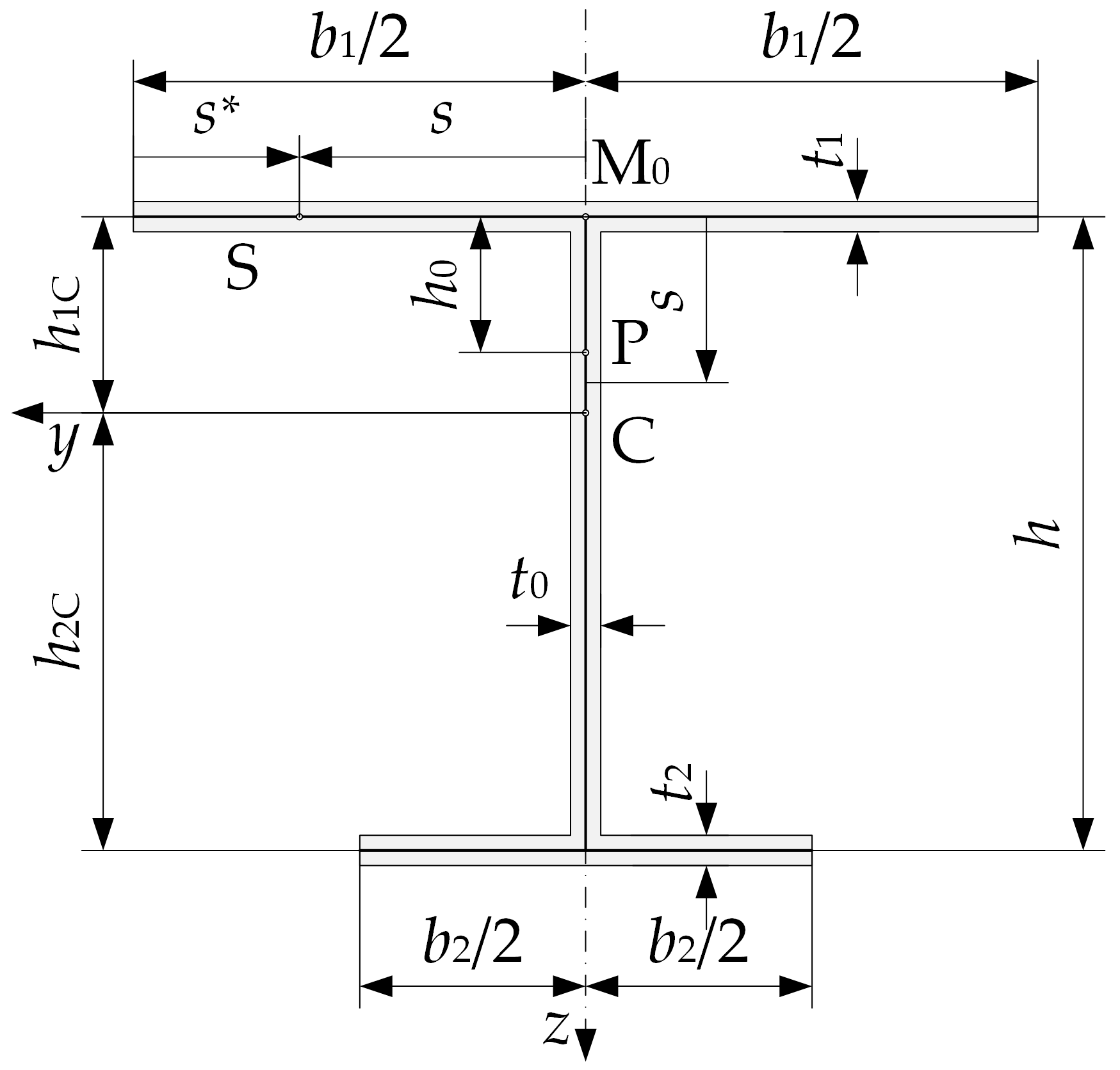
Figure 1. Monosymmetric I section.
Applmech 06 00068 g001
Figure 2. Angular displacements of the cross-section due to bending and shear about the y-axis (a) and z-axis (b).
Applmech 06 00068 g002
Figure 3. The beam model: (a) distributed load on monosymmetric I section; (b) 3D FEM model.
Applmech 06 00068 g003
Figure 4. Stress distributions for orthotropic beam along cross-section contour at x = h for l/h = 3, b1/h = 2, and b1/b2 = 4 (scale: 100 mm = 1 MPa): (a) normal stress σx and (b) shear stress τ.
Applmech 06 00068 g004
Figure 5. Stress distributions for orthotropic beam along cross-section contour at x = l/2 for l/h = 3, b1/h = 2, and b1/b2 = 4 (scale: 100 mm = 1 MPa): (a) normal stress σx and (b) shear stress τ.
Applmech 06 00068 g005
Figure 6. Stress distributions for orthotropic beam along cross-section contour at x = l − h for l/h = 3, b1/h = 2, and b1/b2 = 4 (scale: 100 mm = 1 MPa): (a) normal stress σx and (b) shear stress τ.
Applmech 06 00068 g006
Figure 7. Undeformed and deformed configurations for l/h = 5, b1/h = 2, and b1/b2 = 4 obtained by: (a) TBTS (MATLAB) and (b) FEM (ADINA).
Applmech 06 00068 g007
Figure 8. Total displacements for isotropic beam-column (l/h = 5, b1/h = 2, and b1/b2 = 4) for lines: (a) A, and (b) G.
Applmech 06 00068 g008
Figure 9. Total displacements for orthotropic beam-column (l/h = 5, b1/h = 1, and b1/b2 = 2) for lines: (a) A, and (b) G.
Applmech 06 00068 g009
Table 1. The normal stress relative differences calculated at section x = l/2 for b1/h = 2.
IsotropicOrthotropic
b1/b2l/h, Line σ ˜ x TBTS σ ˜ x VL σ ˜ x TBTS σ ˜ x VL
23, A1.194−24.9271.705−38.143
3, B−0.882−21.423−5.179−35.332
3, C−1.024−12.4523.925−13.196
3, D−0.5779.3167.84545.177
3, E16.119154.52512.467−66.598
5, A−0.034−13.671−0.444−26.924
5, B0.009−10.889−1.356−22.430
5, C−0.223−6.6071.495−10.540
5, D−0.1842.1400.81411.656
5, E0.31926.918−9.925110.506
43, A1.335−20.9171.805−34.170
3, B−0.814−16.553−5.091−30.378
3, C−1.193−6.1323.870−5.099
3, D−0.42619.3918.06163.097
3, E15.876172.870−3.05620.109
5, A−0.013−10.899−0.347−22.980
5, B0.018−7.593−1.292−17.530
5, C−0.276−2.6131.305−3.953
5, D−0.1367.3600.89722.117
5, E0.43733.118−8.191130.485
Table 2. The normal stress relative differences calculated at section x = l/2 for b1/h = 1.
IsotropicOrthotropic
b1/b2l/h, Line σ ˜ x TBTS σ ˜ x VL σ ˜ x TBTS σ ˜ x VL
23, A−0.814−15.071−3.582−30.631
3, B−0.521−13.433−3.595−27.628
3, C0.120−10.3801.494−17.693
3, D−1.869−6.531−7.227−9.498
3, E−6.00614.985−51.01559.820
5, A−0.022−6.300−1.263−16.083
5, B0.099−5.636−1.069−14.468
5, C−0.144−4.9090.171−10.761
5, D−0.699−3.376−2.336−7.052
5, E−1.1903.976−9.13213.187
43, A0.372−7.298−3.245−28.305
3, B0.628−7.737−3.189−24.613
3, C−0.117−10.0011.880−13.306
3, D−6.440−23.444−6.117−1.889
3, E7.35712.674−44.30685.724
5, A1.456−1.638−1.071−14.218
5, B1.518−1.904−0.866−12.142
5, C−0.054−4.1880.249−7.759
5, D−7.580−15.333−1.809−2.165
5, E9.55412.313−6.79823.730
Table 3. Euclidean norms of total displacements for an isotropic and orthotropic beam with b1/h = 2.
IsotropicOrthotropic
b1/b2l/h, Line δ ˜ TBTS δ ˜ VL δ ˜ TBTS δ ˜ VL
23, A0.0040.0240.0570.414
3, C0.0020.0090.0320.147
3, E0.0090.0080.2080.118
3, F0.0020.0140.0160.169
3, G0.0010.0120.0670.145
5, A0.0040.0240.0460.564
5, C0.0030.0160.0580.327
5, E0.0230.0110.4050.154
5, F0.0030.0130.0210.220
5, G0.0040.0150.0460.277
43, A0.0040.0200.0520.373
3, C0.0020.0050.0300.106
3, E0.0090.0120.2100.160
3, F0.0030.0130.0260.189
3, G0.0030.0110.0270.157
5, A0.0050.0210.0460.496
5, C0.0030.0090.0550.235
5, E0.0230.0160.4000.195
5, F0.0040.0110.0360.205
5, G0.0040.0090.0370.180
Table 4. Euclidian norms of total displacements for isotropic and orthotropic beam with b1/h = 1.
IsotropicOrthotropic
b1/b2l/h, Line δ ˜ TBTS δ ˜ VL δ ˜ TBTS δ ˜ VL
23, A0.0050.0160.0430.438
3, C0.0030.0120.0400.268
3, E0.0050.0090.0870.191
3, F0.0030.0110.0320.168
3, G0.0020.0090.0400.139
5, A0.0090.0100.0720.422
5, C0.0040.0150.0600.402
5, E0.0110.0130.1380.391
5, F0.0040.0080.0420.170
5, G0.0030.0100.0390.217
43, A0.0050.0150.0410.418
3, C0.0030.0100.0420.243
3, E0.0060.0060.0940.164
3, F0.0040.0100.0460.176
3, G0.0040.0100.0430.153
5, A0.0080.0100.0670.409
5, C0.0040.0130.0650.369
5, E0.0210.0100.1900.308
5, F0.0150.0110.0650.150
5, G0.0100.0130.0490.166
Disclaimer/Publisher’s Note: The statements, opinions and data contained in all publications are solely those of the individual author(s) and contributor(s) and not of MDPI and/or the editor(s). MDPI and/or the editor(s) disclaim responsibility for any injury to people or property resulting from any ideas, methods, instructions or products referred to in the content.