1. Introduction
Modal superposition is a method of linearly combining modal shapes, whether for displacement or strain, that is extensively employed in engineering. Its most common application is in calculating the transient dynamic response of structures, offering considerable savings in time and computational resources compared to direct integration methods [
1,
2]. Another typical application is in evaluating the dynamic response of sites at seismic risk [
3,
4]. Among its numerous applications, this study focuses on its use in reconstructing the deformation of structures within the framework of structural health monitoring [
5,
6]. Modal reconstruction algorithms theoretically enable the reconstruction of the displacement field of an object across its entire domain, based on a limited number of displacement measurements taken at discrete points. It is assumed that the response of the structure to dynamic loading can be accurately described by a certain number of vibration modes only [
7,
8].
Modal reconstruction has various applications, with a notable contribution being the reconstruction of object shapes from partial measurement data [
9,
10]. Consequently, initial steps have been taken towards reconstructing the displacement and strain fields of structures. When considering engineering objects that are isotropic, uniform, and homogeneous with linear elastic behaviour, and which satisfy the compatibility conditions of displacements and Hooke’s law relating strains to stresses, it is possible to infer the stress state of the entire machine from measurements of displacement or strain sensors. This approach proves particularly useful for monitoring machines, where operation is maintained by adhering to a safety factor below the elastic limit.
A significant limitation of modal reconstructions is the selection of modes [
11]. For computational efficiency and resource management, it is generally necessary to consider the smallest number of modes possible. However, mode selection cannot be arbitrary; algorithms must include at least those modes that are significant for describing the dynamic response of the structure under its loading conditions. Consequently, this study aims to compare various mode selection approaches to establish a methodology for structural health monitoring applicable in different contexts.
There are several criteria for modal selection in superposition [
12,
13,
14]. In the domain of modal reconstruction, which is the focus of this research, the criterion proposed by Borget et al. is compared with the results of newly formulated criteria [
15]. The authors analytically develop three mode selection criteria, which, based on modal participation factors or internal strain potential energy, allow for the retention of only those modes significant for reconstructing the deformed shape from displacement or strain signals. Borget’s criterion, which already exists, is based on energetic considerations related to the deformation of the structure, using a finite element (FE) formulation for strain energy. In contrast, the authors have developed two criteria based on displacement measurements, which do not rely on energetic considerations but rather on the directions of excitations leading to mass movement in response to specific loads, by comparing mode participation factors. Of these two criteria, one considers individual excitation directions (DPFC, directional participation factor criterion), while the other combines all directions (GPFC, global participation factor criterion). The final criterion is based on the principle of internal elastic potential energy between stresses and strains (ISPEC, internal strain potential energy criterion). This criterion is independent of the FE solution and relies solely on the deformation signal and the material characteristics. Note that this criterion can be applied using signals from a discrete number of points on the structure, enabling precise mode selection without prior knowledge of the deformation of the entire object—an advantage not offered by existing criteria in the literature [
11,
15]. It should be noted that, due to the mathematical conditions that will be presented later, the number of measurement points multiplied by the number of strain vector components considered must be greater than or equal to the number of modes taken into account.
The reason for comparing results with Borget’s criterion is underscored, as it is based on the energetic contribution of deformation modes according to external strain energy, making it particularly relevant to compare with the ISPEC criterion, which is formulated based on internal strain energy.
The work is divided into three main parts. The first part describes modal reconstruction, situating it within the context of machine operation when material behaviour remains in the linear elastic field and design conditions involve small displacements and strains. The second part, building upon the first, presents the authors’ analytical formulation of the new modal selection criteria they propose. The third part applies these criteria to a numerical case study to highlight the advantages and disadvantages of the proposed techniques, comparing them with the existing procedure of Borget.
2. Modal Reconstruction
Structural health monitoring through modal reconstruction involves three steps: a priori modal analysis based on known geometry, modal decomposition using a measurement signal to calculate the scaling factors of the modal shapes, and the final step, which is the reconstruction of the entire displacement field of the object by appropriately combining the different modal shapes.
2.1. Modal Analysis
The motion of a structure subjected to dynamic loading, can be described by a time-variant array of displacement. Various analytical models exist to describe the dynamic behaviour of a structure, including the free vibration model, which is also called modal analysis. This neglects the effects of damping and assumes the absence of any external forcing. The analytical model is described in detail by Mario and Young [
16]. The equation of motion under the hypothesis of free vibrations can bewritten as follows:
where
is the displacement vector;
is the mass matrix;
is the stiffness matrix.
Free vibration model assumes that the displacement field has a harmonic form:
is called amplitude of motion.
is the frequency. Substituting Equation (
2) into (
1), an eigenproblem is obtained:
The eigenvalues
are the frequencies of the expanded modes, and the eigenvector
are displacement amplitudes called mode shapes. Mode shapes are usually normalised in mass:
From Equation (
4), it is possible to write the first orthogonality condition:
The second orthogonality condition is obtained by Equation (
3) in terms of normalised mode shapes and Equation (
5):
2.2. Modal Decomposition
Assuming small deformations in elastic range, modal decomposition is the method by which the displacement field of a structure is expressed as a linear combination of the mode shapes describing its dynamic behaviour [
17,
18,
19,
20]:
where
is the modal shape matrix;
is the modal coordinate vector, also called modal amplitude vector.
If n measurement points are considered on the object to be examined and if (degrees of freedom) can be measured on each point, then is a column vector of rows, and is a matrix of rows and m columns, where m is the number of modes assumed capable of constructing the deformation. This means that is a column vector of m rows, and each of its terms represents the weight that the individual mode has in the representation of the deformed shape.
As far as structural health monitoring is concerned, it is often of interest, given the variety of strain-measuring sensors that can be installed on objects, to conduct modal decomposition and subsequent reconstruction from strain measurements [
21,
22,
23,
24,
25]. The six components of strain, three dilatations and three distortions, at each point of the structure are completely determined by the three translations of the displacement field. The relationship between displacements and strains is called conditions of compatibility [
26]:
where
is a simmetric tensor, called Cauchy tensor.
is the displacement field containing of only translations. The modal decomposition in terms of strains can be obtained by considering the conditions of compatibility, so that the continuity of displacement functions defining the deformation is guaranteed [
26] and there is no separation between its parts. Substituting Equation (
7) into (
8), it is possible to write the relationship between strains and modal shapes:
If the modal coordinate vector
is hypothesised to be a function only of the displacements and not of the directions, it can be taken out of the gradient operator:
where
is the condition of compatibility in terms of normalised modal displacement vector for
i-th mode. Defining
the Cauchy tensor for the
i-th mode in terms of normalised strains, it is possible to write the following:
Exploiting the symmetry of the Cauchy tensor and defining
as the vector having dilatations and distortions as components, it is possible to express the modal decomposition for strains:
where
is a matrix having for columns the strains associated with the
m modes considered. Note that Equations (
7) and (
12) are written as a function of the same modal coordinate vector
, which must be independent of the three directions
x,
y, and
z in order to guarantee the compatibility. Each term of the modal coordinate vector
represents the scalar factor to be multiplied by the displacement or strain vector, associated with the individual mode, to obtain the object’s real deformation. Under the assumption of independence of modal coordinates from the three directions of space,
can be calculated from the modal decomposition in terms of displacements or strains indifferently. Equations (
7) and (
12) represent two linear systems of equations. The components of
are the unknowns. In order to compute
, it is necessary that
[
27]. In fact, if the number of unknows is major than the number of equations, the problem can admit infinite solutions. If these two numbers are equal,
can be calculated from Equation (
7) or (
12), inverting
or
, respectively. In general, when
, the pseudoinverse operation is valid:
2.3. Modal Reconstruction
Once the modal coordinates are known, a reconstruction approach takes place so that the deformation of the whole structure is determined. Consider a meshed geometry. All nodes in the mesh are points of interest for the evaluation of displacements and strains. Because
has been computed from Equation (
13) or (
14), the unknown fields can be estimated by modifying Equations (
7) and (
12) using modal displacements and strains for all the nodes of the mesh, which have been estimated analytically, experimentally, or from a previous modal analysis. Under the assumption of small displacements and strains, the advantage of this methodology is that
and
are characteristics of the investigated structure. So, they do not require any further updating, and then, if the modal reconstruction is compared to FEM (finite element method), it is faster and cheaper in terms of calculation time and computational costs [
28,
29].
In addition to the visualisation of the displacement and strain field, it is of great interest to have an estimate of the stresses of the entire body to be monitored. Being in elastic domain and considering the reconstructed strains, this can be done by taking Hooke’s law into account [
30]:
where
is the stress vector and
the elastic matrix:
G and
are the elastic material properties, called shear modulus and Poisson ratio, respectively.
In conclusion, under the assumption of small displacements and strains where the elastic constitutive law is valid, reconstructing a field of displacements or strain through the decomposition and subsequent modal reconstruction approach results in being able to assess the overall stress state.
2.4. Reconstruction Error
In order to assess the goodness of reconstruction of the deformed shape, two relative error functions, one for displacements [
27] and one for strains, are introduced.
and
are the displacement and strain reconstruction errors, respectively. The terms with the subscript
refer to the reconstructed solution and without subscript to the FE solution.
3. Analytic Formulation of the New Mode Selection Criteria
Because the modal decomposition has a solution, it is necessary to retain only a certain number of modes that is smaller than or equal to the number of measurement locations. In addition, in order to obtain a reconstructed shape that accurately represents the real deformation, the mode selection is fundamental. In this regard, static reconstructions are considered. In fact, different methods are applied in order to retain modes for the reconstruction of displacement or strain fields of different static simulations, in which only static loads are considered. So, and are considered time-invariant vectors in this context.
The Borget’s is already established in the literature [
11,
15]. However, the authors have analytically developed and proposed the directional and global participation factor (DPFC and GPFC) criteria, along with the internal strain potential energy criterion (ISPEC).
3.1. Directional and Global Participation Factor Criteria (DPFC and GPFC)
A participation factor is a scalar that provides a measure of how strongly a certain mode contributes to the response of a structure when subjected to a force in a certain direction. This means that a larger participation factor will have a greater contribution to the dynamic response of the structure [
31]. If mass-normalised mode shapes are considered when one performs a modal analysis, the participation factor for the
i-th mode can be defined as follows [
32,
33]:
where
is the vector describing the direction of excitation. Considering a node with six degrees of freedom, the vector
is defined as follows:
where
Assuming the possibility of expressing the real deformation of the machine as a vector of nodal displacements on a discretised geometric model that describes it, the authors define the participation factor associated with the actual deformation of the object as follows:
where
is the normalised mass displacement vector, which can be computed by modifying the mass normalisation formulation for mode shapes from (
4).
The participation factor of the real deformation indicates an estimate of the response of the structure subjected to the load under consideration. This scalar number can be seen as a linear combination of the participation factors of the modes contributing to the response of the structure to that load. In the same way, from the modified Equation (
7) for the reconstruction, the reconstructed displacement vector
is the unknown of the problem. Its normalisation results in the following:
The formulation of participation factor from Equation (
21) is taken into account in order to describe the direction of deformation of the reconstructed solution:
Substituting Equation (
23) to Equation (
24):
Considering Equation (
7), it is possible to express
in function of the modal shapes:
Taking into account the first orthogonality condition from Equation (
5), the participation factor of the reconstructed solution can be expressed in terms of the participation factor of all expanded modes:
For each
i-th mode, the reconstruction contribution is measured as follows:
The authors define the reconstruction capability of each mode as the ratio between
and
:
It is possible to introduce two approaches, one that considers participation factors divided by excitation direction (DPFC) and another that considers all of them (GPFC).
The DPFC (directional participation factor criterion) considers the participation factor individually for each translation and rotation. Therefore, a reconstruction capability is set for each case, and the modes that are significant for each excitation taken individually are retained.
The GPFC (global participation factor criterion) is based on considering a single participation factor that takes into account the combination of all excitation directions, replacing the direction vector
with the unit vector:
Therefore, considering solely the
, it is possible to retain only those modes deemed significant for describing the dynamic behaviour of the structure, taking into account all excitations.
3.2. Internal Strain Potential Energy Criterion (ISPEC)
This mode selection method considers the internal strain potential energy [
30]. The method is already introduced by the authors in [
34]. A more detailed explanation of this method is proposed and compared with the others. The internal strain potential energy can be written as follows:
Considering all expanded modes, it is possible to write the internal strain potential energy of the reconstructed solution. From Equations (
12) and (
31), the reconstructed internal strain potential energy is the following:
For each
i-th mode the reconstruction contribute in terms of internal strain potential energy is as follows:
The reconstruction capability is defined as follows:
where the subscript
refers to the internal strain potential energy associated to the real deformation.
Note that it is possible to calculate the total internal strain potential energy by summing the contribution of strain potential energy associated with the strain of each node describing the discretised domain of the structure. Unlike the methods mentioned so far, which require relationships that impose knowledge of the entire displacement field at all nodes, the ISPEC (internal strain potential energy criterion) can be applied even if only some strain components are known for certain nodes. Note that for Equations (
13) and (
14), the number of measurement nodes times the number of component of the strain vector must be greater than or equal to the total number of expanded modes from which the significant ones are to be selected.
4. Case Study
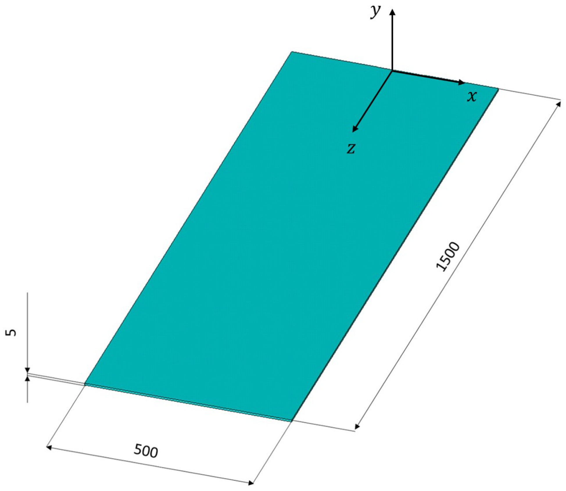
The reconstruction algorithms are applied on a case study consisting of a finite element (FE) model of a plate with dimensions
×
×
(
Figure 1). Structural steel with a Young’s modulus of
, Poisson’s ratio of
, and density of
was chosen as the material.
The plate is a problem that is easily implementable with finite elements. The FE solution is compared with that obtained by modal reconstruction, considering node displacements and deformations as input signals to the algorithm and applying the selection criteria defined analytically by the authors. For the SOLID185 elements (ANSYS Inc., USA, 2020), the homogeneous structural solid formulation with full integration was adopted. The solution was performed using the sparse solver. Modal analyses were carried out with mass normalisation and employing the Block Lanczos method.
The FE model is shown in
Figure 2. It is generated in Ansys APDL (Ansys Parametric Design Language) and modelled with SOLID185 solid elements, which describe 3D structures by elements of eight nodes, having three degrees of freedom at each node: the three translations in the three nodal
x,
y, and
z directions [
35]. The plate is clamped at one end and loaded at the other. Sixty-three different load combinations are considered, alternately and jointly applying forces and moments in the three directions (see
Table 1).
A mesh of two-thousand and twenty-five hexahedral elements was created with three divisions along the thickness, forty-five along the length, and fifteen along the width. Because solid elements have only three degrees of freedom in translation and not in rotation, in order to apply moment vectors, an independent pilot node is defined to distribute the load over a set of dependent nodes, which are those at the end of the plate to be loaded: the pilot node must have six degrees of freedom.
Once the model has been generated, a modal analysis is first performed in order to determine the modal shapes required for the decomposition and subsequent reconstruction of the displacement and strain fields. Normalised results in mass are extracted for fifty modes, considering a diagonalised mass matrix (lumped mass matrix) in order to reduce the calculation time. Through a for loop, the different load combinations, known modal shapes and saved mass and stiffness matrices, are considered, extracting displacement and strain results, which are useful for both decomposition and subsequent comparison and error calculation after reconstruction. The modal decomposition, selection, and reconstruction algorithm is implemented in a Matlab (Matlab R2024a, USA, 2024) script, which allows the Ansys simulations to be launched in succession in batch mode and to proceed to the selection and calculation of the displacement and strain fields, hence also stresses, automatically at each iteration cycle in which the specific load configuration is considered. The outputs of each instance of the for loop are the modes chosen according to each mode selection criterion, the displacement, strain and stress fields, and the reconstruction errors. For the calculation of the modal coordinate vector, only one measurement direction is considered for displacements in the case of the strain energy method and modal participation factors and for strain in the case of the elastic energy potential method. This represents the worst-case scenario in a hypothetical experimental setup where only unidirectional sensors are available and can be arranged in a single direction. In any case, it should be noted that the reconstruction error is minimised when there is the possibility of considering multiple measurement directions, allowing for more accurate detection of the real deformation of the structure.
5. Results and Discussion
In addition to the modal selection criteria formulated by the authors, the Borget’s criterion is also implemented for comparison. The load configuration that considers the three forces and the three moments applied simultaneously in the three directions is considered, as this is the one with the highest number of reconstruction errors. A reconstruction capability threshold of
is adopted for all mode selection methods. Such methods are inherently threshold-dependent, and the choice of this parameter directly influences the approximation level of the reconstructed solution by determining the number of retained modes. In the present work, all modes contributing at least
to the participation factor, strain energy, or internal strain potential energy are considered significant. This choice implicitly assumes that the cumulative participation factor or energy may reach at most
of the actual value, which corresponds to the reconstructed solution with the lowest possible participation factor or energy error, depending on the method applied. In
Table 2,
Table 3,
Table 4, the reconstruction results for each method are presented, showing, for each direction considered in the calculation of modal coordinates, the number of retained modes and the reconstruction error, calculated according to Equations (
17) and (
18).
Firstly, it is possible to notice that the criteria developed by the authors all result in a lower number of retained modes compared to the existing Borget’s criterion.
For the global participation factor criterion, it is noted that high errors are observed for modal coordinates calculated considering individually the x or y directions, which are perpendicular to the plate longitudinal direction. Additionally, in the y direction, which represents the thickness direction of the plate, high errors are also present for the directional participation factor criterion. In general, the results indicate that reconstructions based on modal selection criteria from displacements are significantly affected by the measurement direction. From various analyses, it can be observed that errors are minimised when considering the direction where the displacement derivative is highest. Displacement compatibility relates directional displacement derivatives to strains. Specifically, the case study results demonstrate that compatibility is ensured when the measurement direction, and thus the calculation of modal coordinates, corresponds to the direction with the highest rate of displacement function variation.
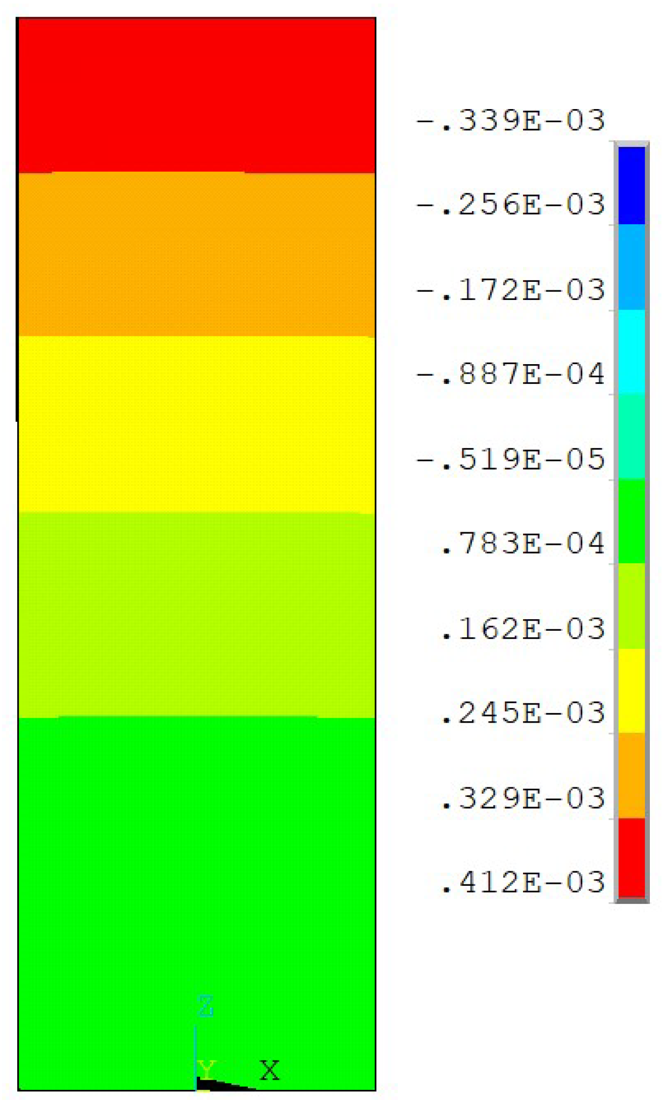
Taking as a demonstrative case the criterion of the directional participation factor, which turns out to have the highest error on the
dilation for modal coordinates calculated according to
y, it is noticeable that the displacement function
, upon which said dilation depends, varies more significantly in the longitudinal
z direction than in the other two (see
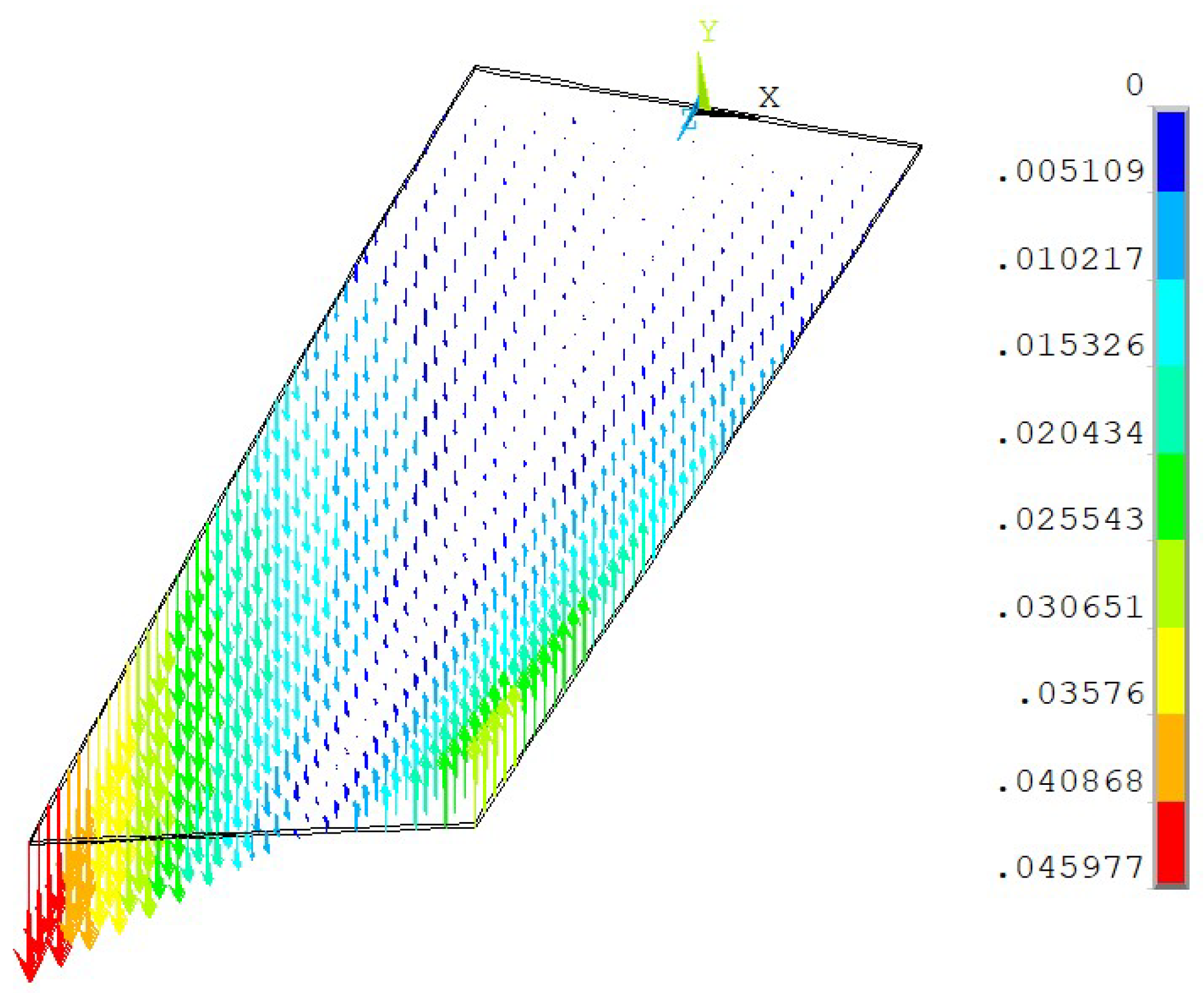
Figure 3). In general, the fact that the rate of change of displacement functions is greater in the
z direction compared to the others is noticeable when considering the vector plot of the resulting displacement vector, which is obtained as the vector sum of
,
, and
. In this regard, from
Figure 4, it is evident that the intensity of the vectors increases significantly with
z and to a lesser extent with
y and
x.
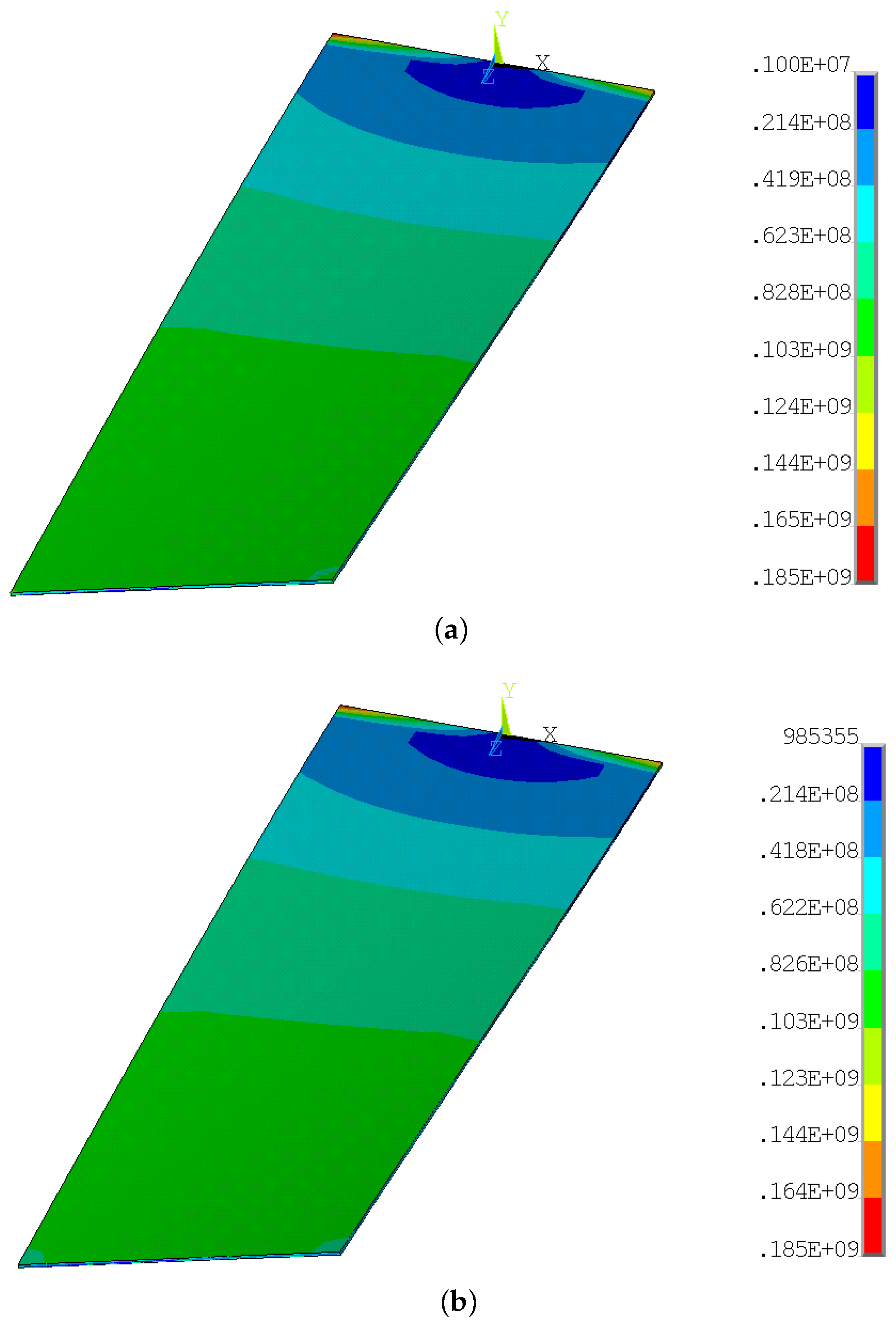
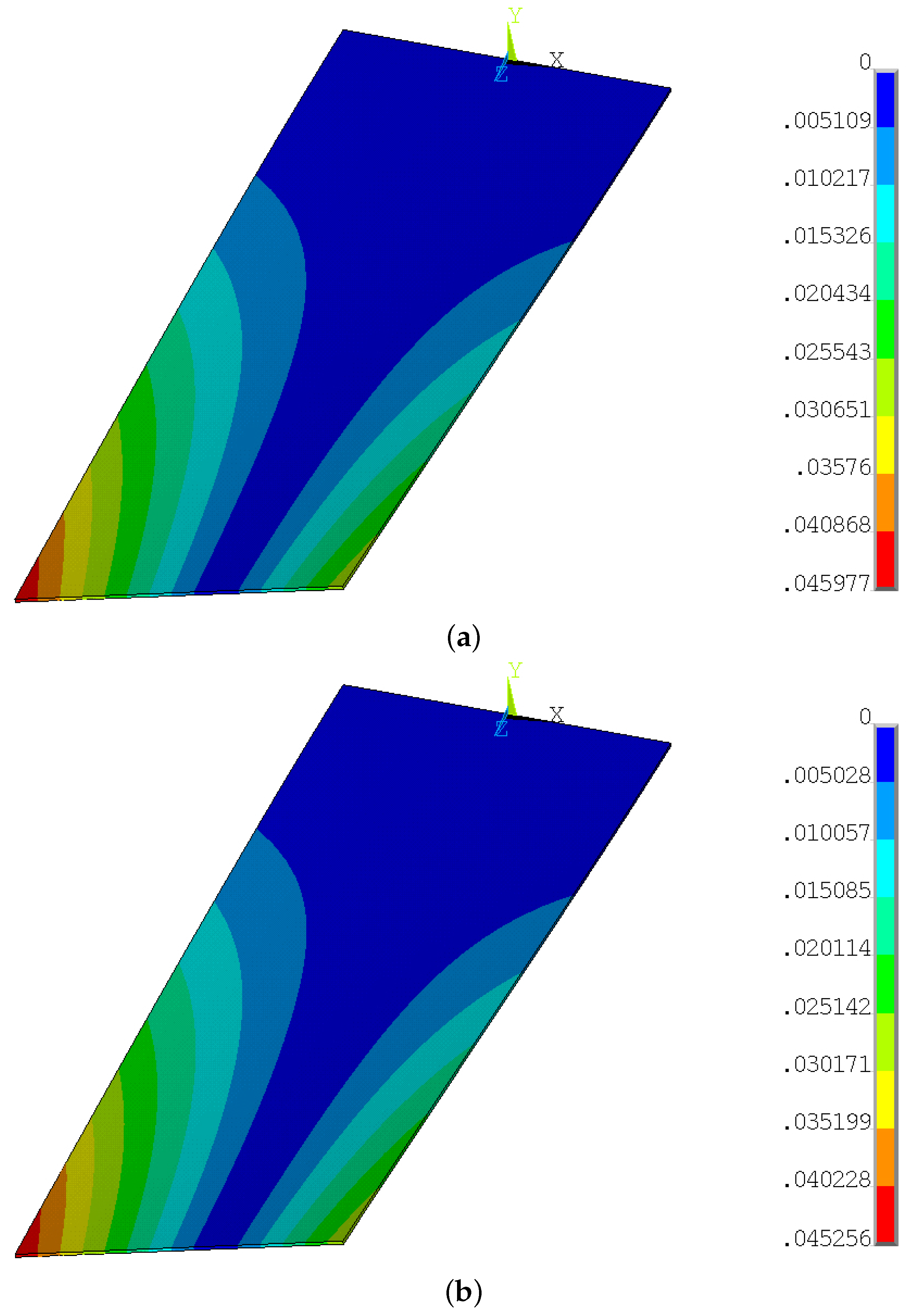
Since the strain field is linearly related to the stress field by Hooke’s law and considering a Von Mises equivalent stress state, valid for ductile materials exhibiting the same behaviour under tension and compression—like the generic structural steel under consideration—stress trends obtained through FE solution are compared with those obtained through reconstruction using the ISPEC method, by way of example (see
Figure 5). For the same purpose, the contour plots of total displacements are also provided in
Figure 6.
6. Conclusions
The aim of this work is to develop and test mode selection criteria for modal reconstruction algorithms. The case study of the thin plate fixed at one end and loaded at the other has highlighted a significant limitation of reconstruction based on displacement measurements: the direction of the measured displacement component significantly affects the error in strain results, consequently leading to stresses that deviate from those actually present on the structure under study. The directional method, despite this limitation, has been retained, owing to its compact formulation, directly derived from displacement decomposition, and its connection to established relationships from undamped free dynamic analysis, such as the participation factor. However, the neglect of deformation aspects remains a substantial drawback, and the results indicate that ISPEC generally provides higher accuracy in strain reconstruction. This is evident from the results obtained by considering different directions of displacement measurements for calculating the modal coordinates necessary for strain field, and consequently stress state, calculation.
The proposed selection criteria have been formulated for linear elastic systems and are therefore applicable, in principle, to any surface, material, or system satisfying the assumptions of linear elasticity and modal superposition (small strains, linear constitutive behaviour, and validity of modal representation). To avoid ambiguity, the class of applications to which the approach is directly applicable includes plate-like components, machine casings, thin structural panels, and certain civil and aerospace panels. The underlying assumptions and limitations (linearity, small deformations, and modal validity) have been explicitly emphasised to ensure clarity regarding the applicability range. The present study also constitutes an initial step towards the development of structural health monitoring (SHM) algorithms that integrate modal selection with machine learning, as will be explicitly stated in both the introduction and the conclusions.
Both Borget’s criterion and the criteria based on participation factors, DPFC and GPFC, obtained by multiplying either the stiffness matrix or the mass matrix, can be applied when displacement measurements are available at all nodes of the FE model mesh. Therefore, these three methods are useful when, given a known displacement solution, it is desired to analyse which modes are significant in adequately describing the dynamic behaviour of the structure under specific loading conditions.
The criterion based on internal strain potential energy (ISPEC) has been developed to create an algorithm that does not require the FEM stiffness matrix while remaining dependent on the material constitutive matrix . As a result, it is designed to be versatile, even in cases where measurement points are not positioned across all areas of the structure, which makes it suitable for SHM applications aimed at strain-field reconstruction. In this context, ISPEC achieves lower strain reconstruction errors than the other criteria and enables the retention of a smaller number of modes while preserving accuracy. Its analytical formulation also allows modal selection without the need to know the strain state at all mesh nodes—only at strategically chosen locations—thereby reducing dependence on the FEM problem, apart from the modal shapes required to compute the energetic contribution of each mode. It should be noted that the number of measurement nodes times the number of components of the strain vector must be greater than or equal to the number of expanded modes from which the significant ones are to be selected. Although some error may arise from not accounting for the full energy contribution due to the deformation of the structure, it is possible to estimate the reconstruction capability of individual modes by considering only the nodes corresponding to the installed sensors.
From the quantitative analysis of the results, ISPEC maintains displacement reconstruction errors within 0.02–4.34%, which are higher than the others. However, ISPEC achieves these results by selecting, on average, 30–40% fewer modes than the directional participation factor-based criteria, thus reducing computational demand without compromising accuracy. This advantage becomes more pronounced when the number of available measurement points is limited, confirming ISPEC’s suitability for experimental SHM scenarios with sparse sensor networks.
All mode selection criteria ultimately have a common limitation: the selection of significant modes cannot be made a priori, but only following a preliminary inversion of Equations (
7) and (
12), calculating modal coordinates for all expanded modes, and subsequent calculation of reconstruction capabilities.
The present work represents an initial step towards the development of SHM frameworks in which modal selection is integrated with artificial intelligence to identify the most relevant modes. A potential strategy involves the creation of synthetic databases of mode shapes and deformations to train machine learning algorithms capable of determining, from discrete measurement points, the set of modes that best reconstructs the deformation field, thereby enabling full-field knowledge of the structure.
The choice of a single rectangular steel plate as the case study has been motivated by the opportunity to present the analytical formulation in a clear and controlled manner, facilitating direct comparison among the proposed criteria. More complex geometries—such as circular plates, stiffened plates, or assemblies of multiple sheets—are expected to modify the number of modes, the degree of mode coupling, and the influence of non-proportional damping effects. These aspects can affect both the mode selection process and the reconstruction accuracy, potentially amplifying the differences between selection methods. Future developments will extend the analysis to such configurations to assess the robustness of the criteria under realistic structural conditions.
Future developments of this activity will involve a study of more complex geometries and experimental objects, such as resin-printed elements for additive manufacturing and steel structures. Additionally, there will be an exploration of the potential application of modal selection criteria on time-varying displacement and deformation signals, investigating how the significance of modes in describing the dynamic behaviour of the structure varies with the temporal variability of loads.
