Article

Influence of Lubricant Properties on Elastohydrodynamic Oil Film Thickness in Angular Contact Ball Bearings: A Numerical Investigation

Department of Aerospace Engineering, Faculty of Engineering, OSTIM Technical University, Ankara 06374, Türkiye
Appl. Mech. 2025, 6(3), 64; https://doi.org/10.3390/applmech6030064
Submission received: 8 July 2025 / Revised: 30 July 2025 / Accepted: 20 August 2025 / Published: 26 August 2025
(This article belongs to the Collection Fracture, Fatigue, and Wear)

Abstract

Predicting oil film thickness at ball–raceway contacts under elastohydrodynamic lubrication (EHL) conditions remains a complex tribological challenge. This complexity arises from dynamic variations in contact load, rotational speed, hydrodynamic effects, and the nonlinear load–deformation characteristics of the contacting surfaces. This study presents a numerical investigation of oil film thickness variations corresponding lubricant properties in rolling bearings using a 5-degree-of-freedom (5-DoF) shaft–bearing model. The model incorporates isothermal EHL and a rigid shaft supported by a pair of angular contact ball bearings. The governing nonlinear equations of motion are solved iteratively via a quasi-static approach, coupling oil film thickness and contact force calculations. Results indicate that oil film thickness increases proportionally with both lubricant viscosity and shaft speed. A twofold increase in shaft speed results in approximately 57% enhancement in film thickness. Similarly, increasing viscosity elevates film thickness proportionally, while the pressure–viscosity coefficient significantly enhances film formation. Notably, the outer raceway exhibits a 13% thicker film than the inner raceway, owing to its higher surface conformity. Furthermore, low-speed operation under heavy loads induces mixed lubrication regimes, compromising film integrity. Results provides insight for lubricant selection and bearing design to mitigate starvation in industrial applications.

1. Introduction

Effective lubrication of rolling bearings is critical to minimize wear, reduce friction, dissipate heat and increase efficiency in industrial applications. The formation of a fully flooded elastohydrodynamic lubrication (EHL) in bearing is required to prevent direct metal contact and extend life. However, predicting film thickness under dynamic loads, varying speeds, and different lubricant properties still one of the major challenge in tribology. Consequently, to analyze the effects of viscosity, pressure–viscosity coefficient, and operating conditions on EHL film thickness in rolling bearings researchers has used theoretical models, experimental setting, and numerical methods.
EHL regime is occur in rolling bearings, when oil pressures as higher as that can lead elastic deformation as well [1,2,3,4]. The classical Dowson-Higginson equation provides a semi-empirical relation for minimum film thickness, considering the influence of speed, load, and lubricant properties. Hamrock and Dowson [5,6] established foundational theories for fluid film lubrication, accounting for surface compliance, lubricant rheology, and temperature effects. EHL modelling has been improved by studies on pressure–viscosity relationships. Roelands [7] introduced a correlation model accounting for the effect of pressure and temperature on viscosity of lubricant. The impact of pressure–viscosity coefficients has been further elaborated by Khonsari and Booser [8] under high loads. Harris and Kotzalas [9] extended this analysis by showing the significance of contact geometry and lubricant rheology. It can be seen from these studies that the viscosity–temperature–pressure relationship is crucial, as defined by ASTM D2270 [10].
Liu et al. [11] highlighted the effect of lubricant temperature on angular contact ball bearing dynamics, showing that increased temperature decreases film thickness and modifies system stiffness and damping characteristics. They emphasized that the lubricants should be chosen based on the operating temperature. To investigate effect of lubricant properties change, Guimarey et al. [12] evaluated the biodegradable base oil with nanoadditives. They demonstrate that nanoparticles significantly improved friction reduction and load-carrying capacity. They show that film thickness from optical interferometry deviated from Hamrock–Dowson predictions by 11% at 30 °C and 3% at 80 °C. Liang et al. [13] studied starvation in rolling bearings experimentaly and found that elevated temperatures accelerate starvation onset, reducing film thickness. Gao et al. [14] investigated how different thermal conditions affect elastohydrodynamic lubrication (EHL) film formation by comparing three heating methods: heating the oil and ball, heating the disc, and uniformly heating the entire system. Their findings reveal that the inlet oil temperature primarily governs the overall film thickness. However, local film formation is influenced by both the thermal gradient effect and the thermal-viscosity wedge effect. Notably, these effects can enhance local film thickness beyond what would be expected from viscosity reduction due to temperature alone. MacLaren and Kadiric [15] investigated high-speed EHL behavior with thin-film interferometry technique, concluding that thermal effects dominate at extreme speeds, causing sliding and film thinning. They measured significant deviation from the isothermal film thickness prediction when above 20% sliding to roll ratio.
Several numerical models have been developed to predict EHL film behavior also. Rahnejat and Gohar [16] incorporated the isoviscous contribution into the dimensionless contact force expression in bearing derived by Mostofi [17] from EHL solution for pure squeezing motion. Hirani et al. [18] introduced a rapid performance evaluation method for journal bearings. Wang et al. [19] investigated EHL in reciprocating motion, showing that film thickness increases with speed but decreases under high loads. Wijnant et al. [20] has obtained the EHL contact characteristics to investigate influence of the lubrication. Dietl et al. [21] proposed an empirical relation for damping in EHL contacts. In these studies the simultaneous solution of the governing equations introduced.
Dynamic loading effects have been examined by Zhang and Glovnea [22] for grease-lubricated EHD (ElastoHydroDynamic) point contacts under sinusoidally varying normal loads. They observed that higher load frequencies attenuated film thickness variations due to the lubricant’s viscoelastic behavior, indicating that dynamic response is strongly frequency-dependent. They expressed that the film thickness recovers about 19% of the fully flooded values for the grease that has the largest base oil viscosity. Zheng et al. [23] analyzed misaligned journal bearings with lubricants, concluding that increased viscosity and film thickness mitigate misalignment effects. They show that viscosity-pressure effect provided an enhancement to viscosity, friction coefficient, and the maximum film pressure, especially for large misalignment angle. Shetty et al. [24] explored also the role of radial vibrations in grease-lubricated deep groove ball bearings, concluding that controlled vibration amplitudes can enhance lubricant replenishment and increase film thickness by 10–25%, whereas excessive vibration induces instability. Paudel et al. [25] investigate a propulsion system dynamic behavior under varying operational conditions with an experimental test rig and an FEM (Finite Element Method) model. Bearing stiffness in the propulsion shaft system calculated by updating the natural frequencies and vibration amplitude of the FE (Finite Element) model according to obtained values from experimental setting. Liu et al. [26] introduces a rotor–rolling bearing dynamic theoretical model including EHL oil film. They considered isothermal EHL for contact model. They show that time-varying stiffness from lubricant films introduces nonlinearities influencing vibration response.
Experimental studies validate the need for sufficient film thickness. Khonsari and Booser [8] expressed importance of oil film thickness for starvation at low speeds and high loads. Moshkovich et al. [27] reported starvation and EHL-to-boundary transitions, emphasizing the role of roughness and materials. Zhai and Chang [28] developed a deterministic thermal model for mixed-film lubrication, emphasizing the impact of asperity contact on film integrity. Lu and Khonsari [29] show that sufficient speed is required to establish a full hydrodynamic film. Stachowiak and Batchelor [30] report higher base oil viscosity enhances film thickness, though it can elevate friction at low temperatures. Wang et al. [31] investigated surface roughness parameters, revealing smoother surfaces enhance EHL performance.
Wear prediction and surface topology have also received attention. Winkler et al. [32] numerically modeled wear in thrust roller bearings under mixed EHL. They used the Greenwood–Williamson model for asperity contact and for the lubrication conditions they obtained by a FEM-based 3D EHL model which is coupled with surface topography changes. From the results they show that a low velocity, higher load and low oil viscosity lead to more wear. Wu et al. [33] combined mixed lubrication theory with quasi-dynamic modeling (Newton-Raphson method) for angular contact ball bearings. Results show that asperity interactions dominate friction. They expressed that frictional coefficient can be decreased when speed increases due to reduced asperity contacts, and enhanced hydrodynamics. Cordier et al. [34] examined roughness orientation effects in EHL contacts experimentally. They show that surfaces exhibiting longitudinal roughness tend to form thinner lubricant films compared to surface with transverse roughness. They stated for rolling element bearings that the influence of roughness is not considered in most cases due to their low roughness amplitude around 0.2 μ m.
These studies demonstrate that lubrication performance in EHL and bearing systems is governed by a complex interplay of operating dynamics, material properties, geometric factors, and thermal effects. Recent computational and high-speed studies have provided new predictive capabilities. Issa et al. [35] applied machine learning (ML) model is based on Gaussian Process Regression to film thickness prediction in EHL elliptical contacts. They used Moes dimensionless parameters group as a feature for the ML model that can be derived from the dimensionless group used in Dowson-Hamrock for oil film thickness equation. They stated, the model achieving high accuracy and offering a rapid alternative to conventional models.
It is seen from literature briefly that, in order to analyze bearing lubrication either experimental setting established or mathematical model employed. Experimental settings, generally includes Optical Interferometry, Pin-on-disk tribometers or load/speed controlled bearing test rig [12,13,14,15,19,29,30,34,36,37,38]. For theoretical studies, mostly isothermal oil film thickness and oil pressure obtained from solution of governing equations (Reynold’s equation, elastic deformation equation, Pressure-Viscosity relation) applying numerical methods such as FEM, FDM (Finite Difference Method), Multigrid Method or FFT based method [16,25,26,32,33,39,40,41,42,43]. Then, curve fitted to the results for analytical approximation. For mixed lubrication regimes, asperity contact model is considered and for thermal EHL, energy equation with Reynolds equation are solved simultaneously. These tools guide lubricant choice and bearing design.
In this work, to determine the oil film thickness and the influence of lubrication property, an overhang rigid shaft supported by angular contact ball bearing is used as a whole system. Oil film thickness calculated by using numerical solution of 5-DoF equation of motion of shaft-bearing system for different lubricants and shaft speed. EHL oil film thickness calculated in each contact at every time instant with the developed algorithm in MATLAB® 2023. Influence of lubricant properties and shaft speed and geometry on oil film thickness provided from results.

2. Model of Overhung Disc–Shaft–Ball Bearing System

In bearings, the thickness of the oil film in the ball-rings contact varies at every time step due to dynamic loads, oil pressure, contact geometry, contact angle, and contact footprint that change depending on the rotation of the shaft. Therefore, in order to select an appropriate lubricant and ensure that the system operates within a suitable lubrication regime, it is involved to evaluate the oil film formed in the bearing throughout a complete revolution of the rolling element. Hence, reduction of frictional losses and the extension of the system’s operational lifespan of the machine design can be achieved. To analyze the oil film in the bearing, a shaft–bearing as a whole is modeled in this study. The modeled overhung disk–shaft–bearing assembly shown in Figure 1. In this configuration, the overhung disk is attached outside the bearings. Such configurations are commonly found in various industrial systems, such as turbines, fans, and propulsion systems. In the modeling process, it is considered that shaft is rigid due to it has significantly higher stiffness when it compared to the bearing’s. Moreover, since the bearing is capable of supporting moment loads, an angular contact bearing is included in the model.
To calculate the oil film in the angular contact bearings presented in the model shown in Figure 1, it is necessary to determine the ball–raceway contact region. For this purpose, the curvature sum, contact geometry, and contact footprint should be determined for the contact between non-conformal bodies, like as the ball and the raceway, as illustrated in Figure 2a. Harris [44] demonstrated the relations between the curvature difference, the ellipticity, 1st and 2nd elliptic integrals. In order to determine the contact region for each ball, as shown in Figure 2b, an analytical solution is employed to compute the Hertzian elliptical contact [45].
Determining the oil film in the contact it is involved the solution of the main equations (Reynolds equation, elastic deformation equation, and rolling element motion equation) simultaneously that given in Elastohydrodynamic Lubrication (EHL) theory. However, as a practical approach adopted in literature, quasi-static method can be used by employing empirical oil film thickness equation, which offers improved solution stability and reduced computational cost [42,46,47].
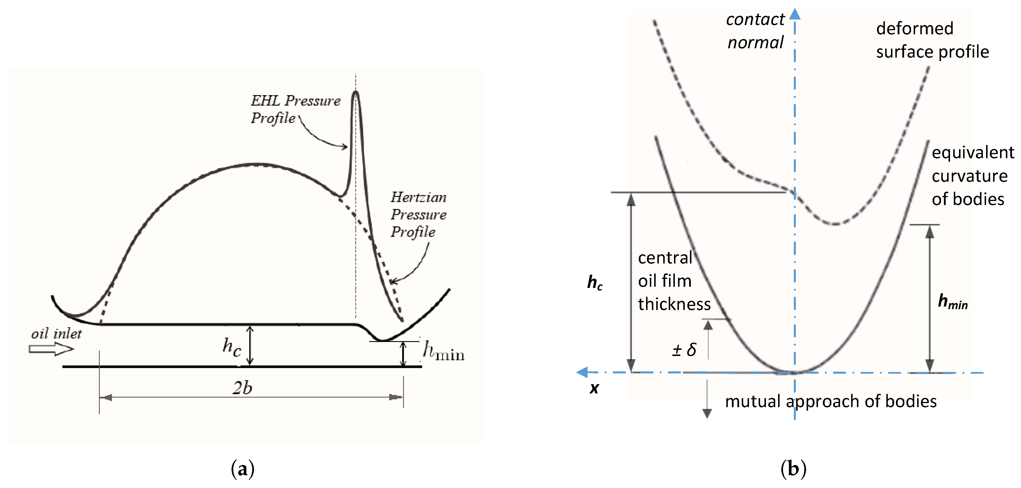
The EHL pressure in the ball–raceway contact follows the Hertzian contact profile; however, it deviates particularly at the outflow sector of the contact since the pressure rise up caused by reduction, which induce growth in lubricant viscosity. The EHL pressure distribution obtained from the solution of the EHL fundamental equations in the contact region is presented in Figure 3a. The oil layer formed because of the mutual approach of the bearing elements, along with the corresponding surface deformation profile on the equivalent surface, is shown in Figure 3b.
From Figure 3b, the interaction of the oil film thickness h, elastic deformation d and the mutual approach of the components δ in any ball–raceway contact can be expressed by Equation (1). In this study, thickness of the oil film is calculated using the expression provided by Dowson and Hamrock, given in Equation (2) [1,2,6]. In Equation (2), the dimensionless speed parameter is defined as U = η u / ( E R x ) which is corresponding to the lubricant viscosity and surface speed, and inversely related to the effective radius of curvature. The dimensionless material parameter is given by G = E / p i v , a s where E is the equivalent elastic modulus and p i v , a s is the isoviscous asymptotic pressure. The dimensionless load parameter is grouped as W = F / E R x 2 . Therefore, the simultaneous solution of Equations (1)–(3) allows for the evaluation of the contact force, oil film thickness, elastic deformation, and the fully flooded isothermal EHL contact force in the ball–raceway interface [39].
h j = δ j + d j
H c = 2.69 U 0.67 G 0.53 W 0.067 ( 1 0.61 e 0.73 κ )
F j = k e q ( δ j + h j ) 3 / 2 + c δ ˙ j
In Equations (1)–(3), the mutual approach δ of the bearing components is derived from the 5DoF motion of the disk, the contact stiffness k ( δ ) is obtained from Hertzian contact footprint. The damping characteristic in the contact region, c ( δ ) , is obtained using a non-dimensional damping relation [20]. A simplified bearing kinematics is assumed in the modelling [9]. It is assumed that the outer rings of the bearings are firmly attached to housing, while the inner rings rotate with the shaft. Accordingly, the 5DoF equations of motion for the disk–shaft–bearing model shown in Figure 1 can be derivated as Equation (4), incorporating the contact forces generated at the ball–raceway contact in both the left side ( LHS ) and right side ( RHS ) bearings.
M d x ¨ = ( F x ) LHS ( F x ) RHS Q x 1 Q x 2 + M d g M d y ¨ = ( F y ) LHS ( F y ) RHS Q y 1 Q y 2 M d z ¨ = + ( F z ) LHS ( F z ) RHS Q z 1 + Q z 2 I y y ϕ ¨ = + a 1 ( F x ) LHS + b 1 ( F x ) RHS R ( F z cos θ j ) LHS R ( F z cos θ j ) RHS b 2 Q x 2 + I z z ψ ˙ ω ˙ I x x ψ ¨ = a 1 ( F y ) LHS b 1 ( F y ) RHS R ( F z sin θ j ) LHS R ( F z sin θ j ) RHS + b 2 Q y 2 I z z ϕ ˙ ω ˙
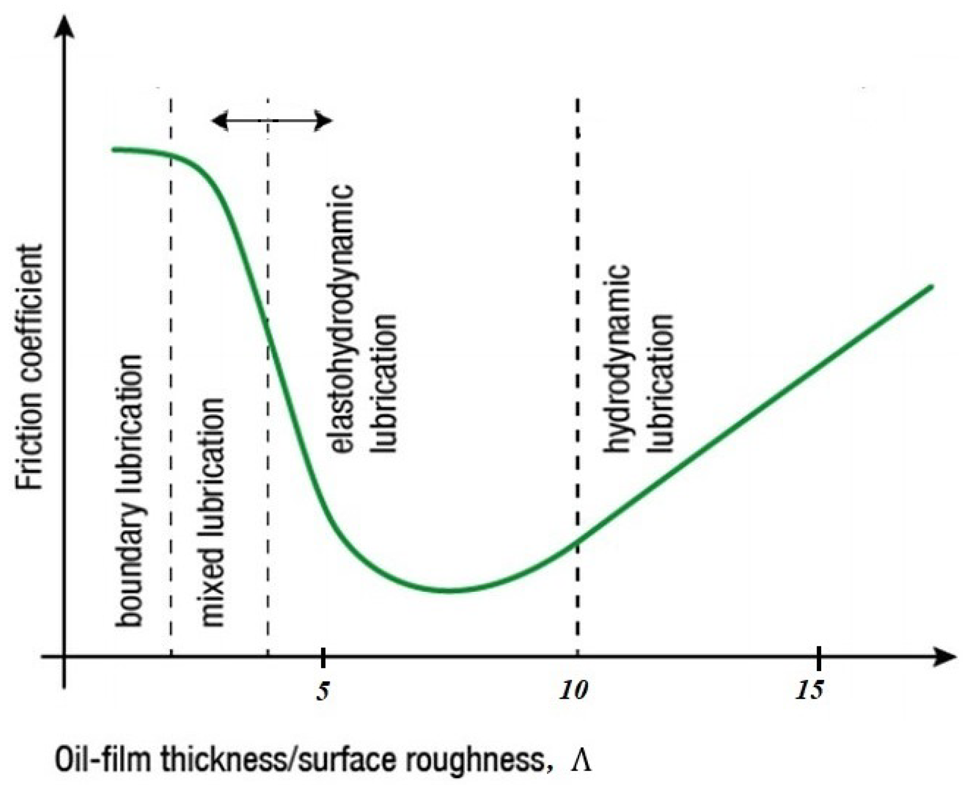
In Equation (4), ψ refers to the rotation about the x-axis, and ϕ indicates the rotation about the y-axis. The angular displacement of each ball can be calculated using the equation θ = γ + ω c t , which represents rotation about the z-axis. Therefore, the cage speed ω c can be determined using the shaft angular speed ω , where γ represents the angular position difference between the balls. The oil film thickness can be used to indicate the coefficient of friction through the Stribeck diagram shown in Figure 4. In the Stribeck diagram, the horizontal axis shows the dimensionless lubricant film parameter Λ or the Hersey number expressed as (viscosity × Speed)/Load. If sufficient lubrication is present in the bearing, the component surfaces will be fully separated by the lubricant film. However, if the film thickness is inadequate, surface asperities will come into contact. This condition is a criteria for identifying the lubrication regime. To determine the prevailing lubrication regime, Equation (5) can be used [2,9].
Λ = h f r 2 + f b 2
where f r , denotes the root mean square (RMS) surface asperities of the raceway, and f b represents the RMS surface roughness of the rolling element. As shown in the Stribeck diagram in Figure 4, the coefficient of friction decreases with increasing film thickness in the EHL regime, while it increases in the hydrodynamic condition. In the EHL lubrication condition, the dimensionless film parameter lies in the 3 < Λ < 10 range. and the coefficient of friction falls within approximately 0.03 to 0.1. For bearings operating within this EHL film thickness range 10 7 h 10 6 m, greases (with thickeners) and low-to-medium viscosity lubricants are generally suitable [1,2].
In the Stribeck diagram, the EHL regime occurs between the mixed and hydrodynamic lubrication regions, where a thin but continuous lubricant film fully separates the contacting surfaces. Under high contact pressures, the lubricant undergoes a significant increase in viscosity (known as the pressure–viscosity effect), while the contacting bodies simultaneously deform elastically. This elastic deformation, combined with the pressure-induced viscosity increase, enables the thin film to support heavy loads with minimal friction. Surface asperities are fully separated, reducing solid contact and wear. As a result, the EHL regime corresponds to the lowest point on the friction curve, indicating optimal lubrication performance under rolling conditions.
To focus on the influence of lubricant properties on oil film thickness, certain modeling assumptions have been adopted in this study. The bearing is assumed to operate under isothermal conditions, and the lubricant viscosity is taken at a constant temperature of 4 0 °C. However, heat generation during operation increases the temperature in machines, which in turn reduces the lubricant’s viscosity and adversely affects film thickness. Although this effect is significant, one of the primary roles of lubrication is also to dissipate heat from the contact region. Therefore, heat can be removed from the contact region by controlling the temperature of lubricant. In addition, Gao et al. [14] show that oil film thickness mainly influenced from temperature of lubricant and twofold increase on temperature of lubricant can reduce oil film thickness around 40%. Whereas, they also show that, oil film formation is influenced by both the thermal gradient effect and the thermal-viscosity wedge effect. Notably, these effects can enhance local film thickness. On the ground that thermal effects and selection of lubricant can be take into account in the design stage of shaft-bearing system. Another key assumption is Newtonian fluid behavior for lubricant. To consider non-Newtonian behavior, Ree–Eyring Model, Bingham Plastic Model or Carreau-Yasuda Model could be incorporated. Surface asperity contact is neglected in the modeling, as the main focus is on the fully flooded EHL regime, which is essential for minimizing friction and wear in bearing contacts. Moreover, in high-precision or high-performance applications, surface roughness (Ra) can be reduced to below 12 nanometer through superfinishing or polishing. Such smooth surfaces are favorable for maintaining EHL conditions, as defined by Equation (5). However, if the asperity height of the contacting bodies in the application exceeds the oil film thickness, mixed lubrication conditions should be considered. Lastly, pure rolling motion is assumed in the kinematic analysis.

3. Results of Numerical Analyses and Discussion

Since the equations of motion are nonlinear, the differential equations is solved numerically using a custom-developed code based on a fixed time-step Runge–Kutta algorithm. For all time instant, the film thickness, elastic deformation, and EHL contact force at all ball–raceway contact are computed iteratively using the Newton–Raphson that algorithm given in Table 1 [48].
The data of the disk shaft bearing system used for the oil film calculation are provided in Table 2.
A total of 38 case studies listed in Table 3 are conducted, as, to investigate the effects of lubricant properties on the film thickness. The results are presented in the time domain with respect to varying lubricant properties. For the presentation of the results, widely used style from the literature is adopted [49,50].
In the simulations, oil film thickness values are obtained by different shaft rotational speed from the range 1000 rpm to 10,000 rpm within 500 rpm increments. Film thickness values are also calculated for various viscosity value of a mineral oil, grease range from 0.04 Pas to 0.4 Pas. Finally, the effect of changes in the pressure–viscosity coefficient on the oil film thickness, within the range of 1 × 10 8 P a 1 to 2.5 × 10 8 P a 1 are investigated. A constant preload of 100 N is applied to the bearings to obtain initial load-deformation values.
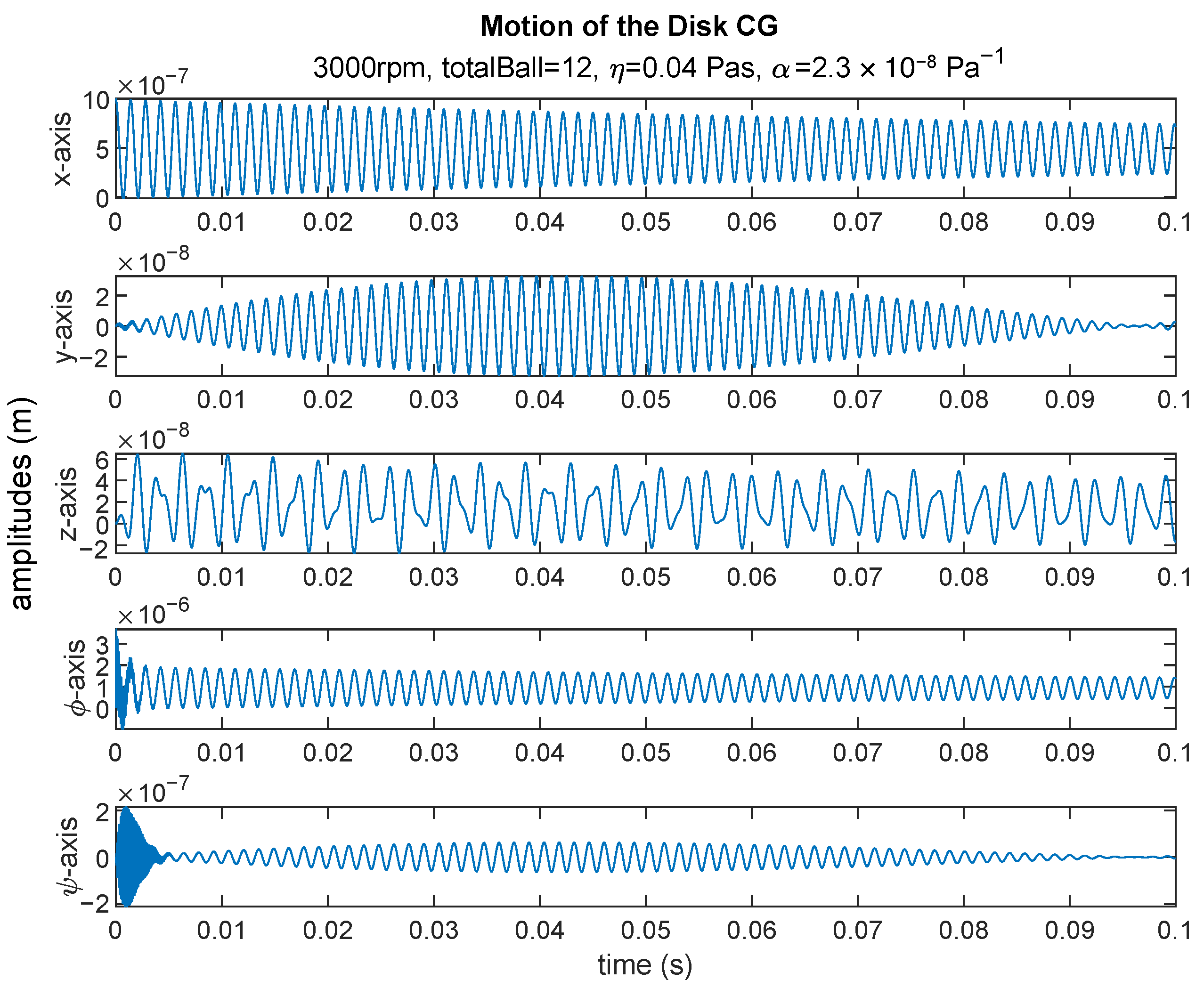
The 5DoF motion of the overhung disc–shaft–bearing system obtained from simulation is illustrated in Figure 5. In this configuration, the disc undergoes translational motion along the x, y, and z axes, while simultaneously subjected to two rocking motions about the x- and y-axes, denoted as ψ and ϕ , respectively. These dynamic behaviors cause continuous variation in the spatial position of the disc’s center of gravity (CG) during shaft rotation. Consequently, the position of each rolling element in the angular contact ball bearings changes over time, leading to continuous alteration in contact angle, contact geometry, Hertzian contact parameters, relative surface velocities, contact forces, oil film thickness, and lubricant pressure. Since the presence of EHL contact affect the contact characteristics, it directly influences the shaft dynamics. However, in this study mainly focused on effects of lubricant properties on the film thickness. Contact characteristics and shaft motion analyses are not in the scope of this work. Detailed information about EHL contact characteristic and shaft dynamic analyses can be viewed from literature [2,20,48].

3.1. Effect of the Speed on Oil Film Thickness

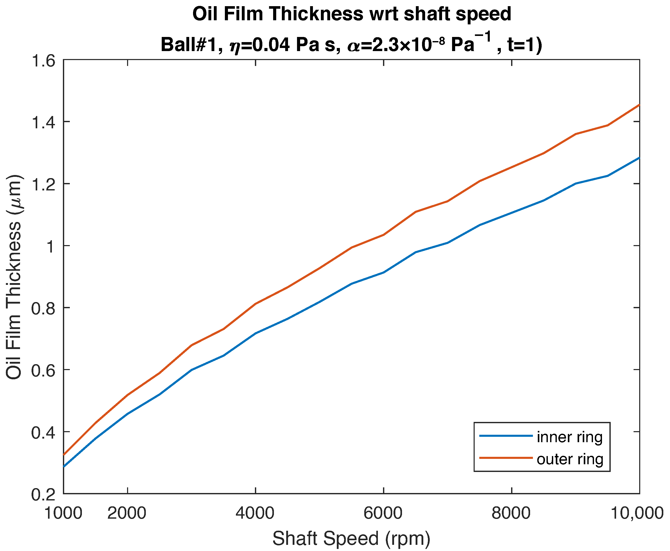
The oil film thickness increases nonlinearly within the range of 0.3–1.5 μ m as the shaft speed varies from 1000 to 10,000 rpm as shown in Figure 6, This is an expected result, since in the Equation (2), the dimensionless speed parameter is proportional to the relative surface velocity u, indicating that rise up speed leads to a thicker lubricant film. Additionally, difference in film thickness at the inner and outer raceways can be seen in Figure 6. This difference arises from the variation in ball–raceway conformity, which defines the degree of fit between the ball and the raceway curvatures. When conformity increases, the contact load decreases; however, due to the enlargement of the contact area, friction also increases. In rolling bearings, a slightly higher conformity is typically applied to the outer raceway to balance the contact stresses between the inner and outer rings. As a result, the oil film formed on the outer raceway is relatively thicker. Table 4 presents the film thickness values for selected shaft speeds. It can be observed that doubling the shaft speed increases the film thickness by approximately 57%, and that the film thickness on the outer raceway is about 13% higher than that on the inner raceway.

3.2. Effect of Viscosity

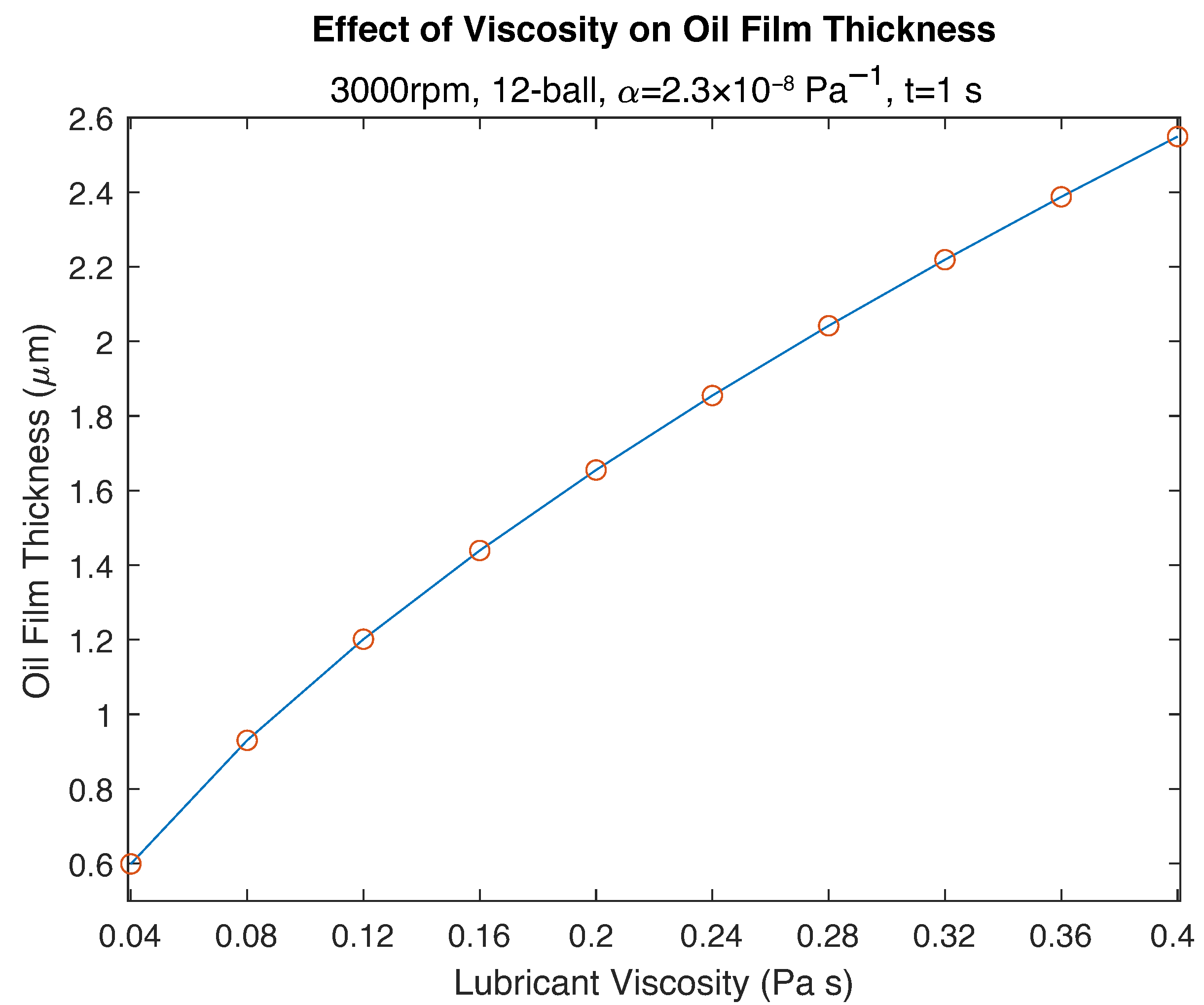
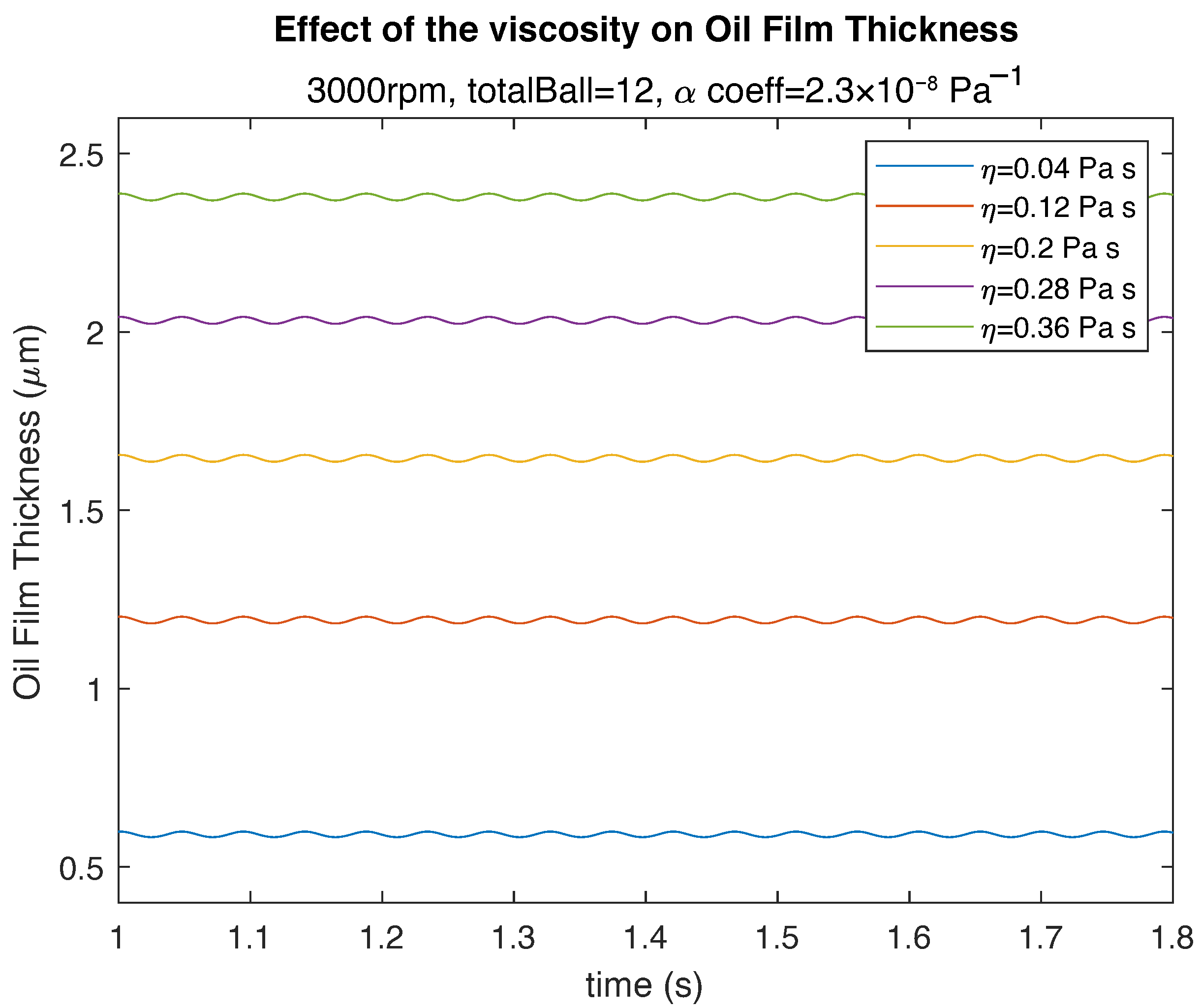
The alteration of oil film thickness according to lubricant properties is presented in Figure 7. In the given results, the shaft speed and pressure–viscosity coefficient taken same value to isolate the effect of various lubricant viscosities on the film thickness. The most clear observation is that the increase in viscosity does not bring about to a linear increase in oil film. As can be seen from the Equation (2), viscosity is included within the dimensionless speed parameter, to which it is proportional. For this reason, escalate in film thickness occur with rising viscosity. However, since the power of the dimensionless speed parameter is 0.67, the correlation between viscosity and film thickness is nonlinear. This nonlinearity is also clearly seen in Figure 8, which shows the time-dependent variation of oil film thickness for selected viscosity values.
In this study, various synthetic and grease lubricants with different viscosity values are used. To provide more insight on the calculated oil film thicknesses, the dynamic viscosities employed in the simulations are converted to kinematic viscosities and are presented in Table 5. The results indicate that a twofold increase in viscosity yield to an approximate 54% growth in film thickness.

3.3. Effect of Pressure-Viscosity Coefficient

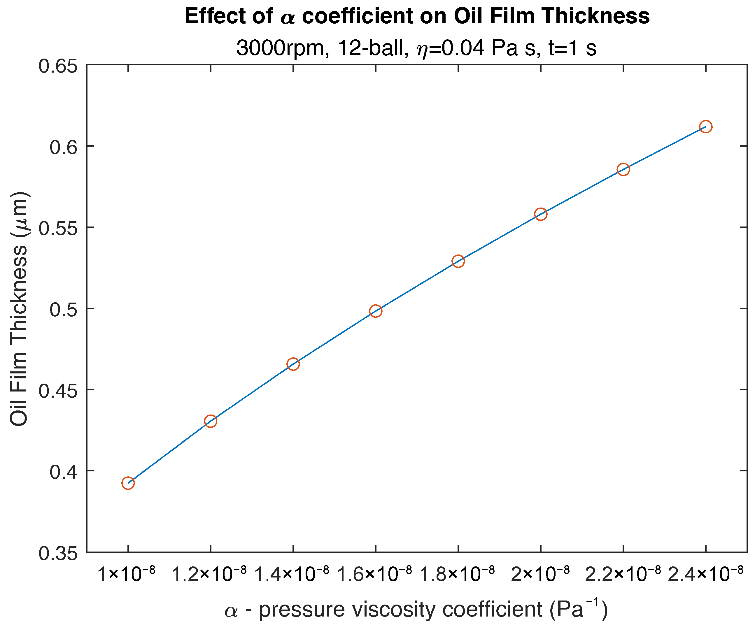
Another important lubricant property influencing the calculation of film thickness is the pressure–viscosity coefficient α . The α coefficient is reported to be inversely related with the isoviscous pressure of the lubricant [1,3,7]. This parameter is incorporated into the nondimensional material parameter G in the film thickness equation, Equation (2). The effect of the pressure–viscosity coefficient on the oil film thickness is presented in Figure 9. A nonlinear relationship is observed, which is attributed to the power of dimensionless material parameter equal to 0.53. Furthermore, it is evident that an rise in the α value yields to an growth in film thickness. However, a twofold surge in the α value yields 42% growth in film thickness.
To determine the contribution of the EHL on the shaft-bearing dynamics, EHL film thickness can be calculated by the Newmark- β numerical solution method also [26]. Significance of lubrication property on oil film thickness obtained in this study is consistent with findings reported in the literature. Therefore, in the formation of the EHL regime, not only the lubricant viscosity but also the pressure–viscosity coefficient must be considered. Additionally, to ensure a fully flooded EHL condition, other factors such as the lubrication method, surface tolerances, and system loads must also be considered. In this study, the focus has been limited primarily on lubricant properties and operating speed, while these additional factors have not been addressed. A comprehensive evaluation of all these aspects would enable more effective designs in terms of efficiency, wear resistance, and service life.

4. Conclusions

In this study, a dynamic disc–shaft–bearing system is employed to investigate the effect of lubricant properties on lubricant film thickness. With the rotation of the shaft, the motion of the overhung disc’s center of gravity (CG) influences the contact characteristics in the angular contact bearing, thereby altering the oil film formation and lubrication regime. The lubrication regime is assumed to be within the EHL (Elastohydrodynamic Lubrication) domain. Surface finishing techniques that reduce surface roughness in bearing components can help prevent asperity contact, which may otherwise compromise the integrity of the oil film. Reducing asperity enhances the correspondence between industrial applications and theoretical predictions, enabling more accurate validation of film thickness using the Stribeck diagram, as defined by Equation (5). However, such polishing methods may increase the manufacturing costs.
At each time step corresponding to the dynamic motion of the bearing, the oil film formed within the bearing is calculated quasi-statically using the Newton–Raphson technique. To this end, the shaft was simulated using a theoretical model under varying rotational speeds in the range of 1000–10,000 rpm and a constant preload. This approach enabled the investigation of how variations in viscosity and pressure–viscosity coefficient affects the lubricant film thickness. The resulting film thickness values is calculated, consistent with the literature. Based on the results, the following conclusions can be given:
  • Oil film continuously altering at the ball–raceway contact during the rotation of shaft,
  • A twofold increase in shaft speed leads to an approximate 57% increase in oil film thickness,
  • Oil film in the outer raceway is approximately 13% thicker than that in the inner raceway,
  • The effect of viscosity on lubricant film thickness is nonlinear; a twofold increase in viscosity induce nearly 54% increase in oil film thickness.
  • Similarly, a twofold increase in the pressure–viscosity coefficient α causes a 42% increase in oil film thickness.
Therefore, in the formation of the EHL condition, not only lubricant viscosity but also the pressure–viscosity coefficient should be considered. Additionally, factors such as the lubrication method, surface tolerances, and system loads should be considered to ensure a fully flooded EHL condition. A comprehensive evaluation of all these factors can lead to more efficient, durable, and wear-resistant bearing system designs.

Funding

This research received no external funding.

Institutional Review Board Statement

Not applicable.

Informed Consent Statement

Not applicable.

Data Availability Statement

The raw data supporting the conclusions of this article will be made available by the authors on request.

Acknowledgments

During the preparation of this manuscript/study, the author used MATLAB 2023 for the purposes of numerical analyses. The authors have reviewed and edited the output and take full responsibility for the content of this publication.

Conflicts of Interest

The author declare no conflicts of interest.

Abbreviations

The following abbreviations are used in this manuscript:
EHLElastoHydrodynamicLubrication
EHDElastoHydroDynamic
FEMFinite Element Method
FDMFinite Difference Method
EOMEquations of Motion
CGCenter of Gravity
DoFDegree of Freedom
LHSLeft Hand Side
RHSRight Hand Side

References

  1. Hamrock, B.J.; Schmid, S.R.; Jacobson, B.O. Fundamentals of Fluid Film Lubrication, 2nd ed.; CRC Press: Boca Raton, FL, USA, 2004. [Google Scholar]
  2. Hamrock, B.J.; Dowson, D. Ball Bearing Lubrication: The eLastohydrodynamics of Elliptical Contacts; John Wiley & Sons: Hoboken, NJ, USA, 1981. [Google Scholar]
  3. Khonsari, M.M.; Booser, E.R. Applied Tribology: Bearing Design and Lubrication; John Wiley & Sons: Hoboken, NJ, USA, 2017. [Google Scholar]
  4. Cameron, A.G.W. The Principles of Lubrication; Longman: London, UK, 1966; ISBN 9780582528804. [Google Scholar]
  5. Hamrock, B.; Dowson, D. Isothermal Elastohydrodynamic Lubrication of Point Contacts I—Theoretical Formulation. NASA TN D-8049; 1975; p. 33. Available online: https://ntrs.nasa.gov/citations/19750022492 (accessed on 1 July 2025).
  6. Hamrock, B.; Dowson, D. Isothermal Elastohydrodynamic Lubrication of Point Contacts III—Fully Flooded Results. NASA TN D-8317; 1976; p. 33. Available online: https://ntrs.nasa.gov/citations/19770004457 (accessed on 1 July 2025).
  7. Roelands, C.J.A. Correlational Aspects of the viscOsity-Temperature-Pressure Relationship of Lubricating Oils. Ph.D. Thesis, Technical University of Delft, Delft, The Netherlands, 1966. [Google Scholar]
  8. Khonsari, M.M.; Booser, E.R. Proper film thickness key to bearing survival. Mach. Des. 2006, 78, 100–104. [Google Scholar]
  9. Harris, T.A.; Kotzalas, M.N. Advanced Concepts of Bearing Technology: Rolling Bearing Analysis, 4th ed.; CRC Press: Boca Raton, FL, USA, 2006. [Google Scholar]
  10. ASTM D2270; Standard Practice for Calculating Viscosity Index from Kinematic Viscosity at 40 and 100 °C. ASTM International: West Conshohocken, PA, USA, 2016.
  11. Liu, Y.; Wang, W.; Qing, T.; Zhang, Y.; Liang, H.; Zhang, S. The effect of lubricant temperature on dynamic behavior in angular contact ball bearings. Mech. Mach. Theory 2020, 149, 103832. [Google Scholar] [CrossRef]
  12. Guimarey, M.J.; Gonçalves, D.E.; Liñeira Del Río, J.M.; Comuñas, M.J.; Fernández, J.; Seabra, J.H. Lubricant properties of trimethylolpropane trioleate biodegradable oil: High pressure density and viscosity, film thickness, Stribeck curves and influence of nanoadditives. J. Mol. Liq. 2021, 335, 116410. [Google Scholar] [CrossRef]
  13. Liang, H.; Fan, Z.; Wang, W.; Zhao, Z. Experimental investigation of the film behavior in a model rolling bearing. Tribol. Int. 2022, 175, 107853. [Google Scholar] [CrossRef]
  14. Gao, J.; Yang, P.; Li, X.; Jin, X.; Tian, Y.; Cheng, Z.; Yan, X. Effects of Oil and Solid Body Temperatures on Elastohydrodynamic Lubrication Film Formation. Lubricants 2024, 12, 28. [Google Scholar] [CrossRef]
  15. MacLaren, A.; Kadiric, A. Elastohydrodynamic Traction and Film Thickness at High Speeds. Tribol. Lett. 2024, 72, 92. [Google Scholar] [CrossRef]
  16. Rahnejat, H.; Gohar, R. The Vibrations of Radial Ball Bearings. Proc. Inst. Mech. Eng. Part C J. Mech. Eng. Sci. 1985, 199, 181–193. [Google Scholar] [CrossRef]
  17. Mostofi, A. Oil Film Thickness and Pressure Distribution in Elastohydrodynamic Elliptical Contacts. Ph.D. Thesis, Department of Mechanical Engineering Imperial College of Science and Technology University of London, London, UK, 1981. [Google Scholar]
  18. Hirani, H.; Rao, T.; Athre, K.; Biswas, S. Rapid performance evaluation of journal bearings. Tribol. Int. 1997, 30, 825–834. [Google Scholar] [CrossRef]
  19. Wang, J.; Hashimoto, T.; Nishikawa, H.; Kaneta, M. Pure rolling elastohydrodynamic lubrication of short stroke reciprocating motion. Tribol. Int. 2005, 38, 1013–1021. [Google Scholar] [CrossRef]
  20. Wijnant, Y.H.; Wensing, J.A.; Nijen, G.C. The influence of lubrication on the dynamic behaviour of ball bearings. J. Sound Vib. 1999, 222, 579–596. [Google Scholar] [CrossRef]
  21. Dietl, P.; Nijen, J.; van Nijen, G.C. Rolling bearing damping for dynamic analysis of multi-body systems—Experimental and theoretical results. Proc. Inst. Mech. Eng. Part K J. Multi-Body Dyn. 2000, 214, 33–43. [Google Scholar] [CrossRef]
  22. Zhang, X.; Glovnea, R. An experimental investigation of grease lubricated EHD contact subjected to normal sinusoidally variable loading. Tribol. Int. 2020, 147, 106272. [Google Scholar] [CrossRef]
  23. Zheng, L.; Zhu, H.; Zhu, J.; Deng, Y. Effects of oil film thickness and viscosity on the performance of misaligned journal bearings with couple stress lubricants. Tribol. Int. 2020, 146, 106229. [Google Scholar] [CrossRef]
  24. Shetty, P.; Meijer, R.J.; Osara, J.A.; Pasaribu, R.; Lugt, P.M. Vibrations and film thickness in grease-lubricated deep groove ball bearings. Tribol. Int. 2024, 193, 109325. [Google Scholar] [CrossRef]
  25. Paudel, A.C.; Doranga, S.; Li, Y.; Khanal, M. System Identification and Dynamic Analysis of the Propulsion Shaft Systems Using Response Surface Optimization Technique. Appl. Mech. 2024, 5, 305–321. [Google Scholar] [CrossRef]
  26. Liu, K.; Shi, X.; Wang, D.; Feng, Y.; Jian, Y.; Li, W. A method for the dynamic characteristic analysis of a rotor-rolling bearing system influenced by elastohydrodynamic lubrication. J. Sound Vib. 2025, 608, 119075. [Google Scholar] [CrossRef]
  27. Moshkovich, A.; Perfilyev, V.; Gorni, D.; Lapsker, I.; Rapoport, L. The effect of Cu grain size on transition from EHL to BL regime (Stribeck curve). Wear 2011, 271, 1726–1732. [Google Scholar] [CrossRef]
  28. Zhai, X.; Chang, L. Some insights into asperity temperatures in mixed-film lubrication. Tribol. Int. 2001, 34, 381–387. [Google Scholar] [CrossRef]
  29. Lu, X.; Khonsari, M.M. On the lift-off speed in journal bearings. Tribol. Lett. 2005, 20, 299–305. [Google Scholar] [CrossRef]
  30. Stachowiak, G.; Batchelor, A.W. Engineering Tribology; Butterworth-Heinemann: Oxford, UK, 2025. [Google Scholar]
  31. Wang, W.z.; Chen, H.; Hu, Y.z.; Wang, H. Effect of surface roughness parameters on mixed lubrication characteristics. Tribol. Int. 2006, 39, 522–527. [Google Scholar] [CrossRef]
  32. Winkler, A.; Marian, M.; Tremmel, S.; Wartzack, S. Numerical Modeling of Wear in a Thrust Roller Bearing under Mixed Elastohydrodynamic Lubrication. Lubricants 2020, 8, 58. [Google Scholar] [CrossRef]
  33. Wu, J.; Wang, L.; He, T.; Gu, L.; Zhang, C.; Lu, Y. Investigation on the angular contact ball bearings under low speed and heavy load with coupled mixed lubrication and quasi-dynamic analysis. Lubr. Sci. 2020, 32, 108–120. [Google Scholar] [CrossRef]
  34. Cordier, M.; Diab, Y.; Cavoret, J.; Majdoub, F.; Changenet, C.; Ville, F. An Experimental Study on the Impact of Roughness Orientation on the Friction Coefficient in EHL Contact. Lubricants 2025, 13, 340. [Google Scholar] [CrossRef]
  35. Issa, J.; El Hajj, A.; Vergne, P.; Habchi, W. Machine Learning for Film Thickness Prediction in Elastohydrodynamic Lubricated Elliptical Contacts. Lubricants 2023, 11, 497. [Google Scholar] [CrossRef]
  36. Majumdar, A.; Bhushan, B. Role of fractal geometry in roughness characterization and contact mechanics of surfaces. J. Tribol. 1990, 112, 205–2016. [Google Scholar] [CrossRef]
  37. Martin, F.A. Oil flow in plain steadily loaded journal bearings: Realistic predictions using rapid techniques. Proc. Inst. Mech. Eng. Part J J. Eng. Tribol. 1998, 212, 413–425. [Google Scholar] [CrossRef]
  38. Muzakkir, S.M.; Hirani, H.; Thakre, G.D.; Tyagi, M.R. Tribological failure analysis of journal bearings used in sugar mills. Eng. Fail. Anal. 2011, 18, 2093–2103. [Google Scholar] [CrossRef]
  39. Bal, H.; Akturk, N. Vibration modeling of wind turbine shaft as rigid shaft supported by EHL contact ball bearings with overhung disc system. Tribol. Int. 2020, 151, 106481. [Google Scholar] [CrossRef]
  40. Karacay, T.; Akturk, N. Vibrations of a grinding spindle supported by angular contact ball bearings. Proc. Inst. Mech. Eng. Part K J. Multi-Body Dyn. 2008, 222, 61–75. [Google Scholar] [CrossRef]
  41. Mostofi, A.; Gohar, R. Oil Film Thickness and Pressure Distribution in Elastohydrodynamic Point Contacts. J. Mech. Eng. Sci. 1982, 24, 173–182. [Google Scholar] [CrossRef]
  42. Zhang, Y.; Liu, H.; Zhu, C.; Liu, M.; Song, C. Oil film stiffness and damping in an elastohydrodynamic lubrication line contact-vibration. J. Mech. Sci. Technol. 2016, 30, 3031–3039. [Google Scholar] [CrossRef]
  43. Lubrecht, A. The Numerical Solution of the Elastohydrodynamically Lubricated Line- and Point Contact Problem, Using Multigrid Techniques. Ph.D. Thesis, Koninklijke Bibliotheek, Den Haag, The Netherlands, 1987. [Google Scholar]
  44. Harris, T.A. An Analytical Method to Predict Skidding in Thrust-Loaded, Angular-Contact Ball Bearings. J. Lubr. Technol. 1971, 93, 17–23. [Google Scholar] [CrossRef]
  45. Antoine, J.F.; Visa, C.; Sauvey, C. Approximate Analytical Model for Hertzian Elliptical Contact Problems. J. Tribol. 2006, 128, 660–664. [Google Scholar] [CrossRef]
  46. Bal, H.; Ateş, K.; Karaçay, T.; Aktürk, N. Effect of Preload on the Vibrations of EHL Angular Contact Ball Bearings: Theoretical and Experimental Results. Lubricants 2022, 10, 46. [Google Scholar] [CrossRef]
  47. Hagiu, G.D.; Gafitanu, M.D. Dynamic characteristics of high speed angular contact ball bearings. Wear 1997, 211, 22–29. [Google Scholar] [CrossRef]
  48. Bal, H. Rüzgâr Türbinlerinde Kullanılan ElastoHidrodinamik Yağlamalı Rulmanların Dinamik Davranışının İncelenmesi. (Investigation of Dynamic Behaviour of Elasto-Hydrodynamic Lubricated Rolling Bearing Using in Wind Turbines). Ph.D. Thesis, The Department of Mechanical Engineering, Faculty of Engineering, Gazi University, Ankara, Turkey, 2018. [Google Scholar]
  49. Zhu, W.; Chen, D.; Shi, J.; Zhang, J.; Zhao, H.; Li, C. Design and optimization of a temperature controller with low overshoot, fast respond and high COP based on water-source thermoelectric heat pump. Appl. Therm. Eng. 2024, 242, 122473. [Google Scholar] [CrossRef]
  50. Chen, D.; Noda, N.A.; Takaki, R.; Sano, Y. Intensity of singular stress fields (ISSFs) in micro-bond test in comparison with ISSFs in pull-out test. Int. J. Mech. Sci. 2020, 183, 105817. [Google Scholar] [CrossRef]
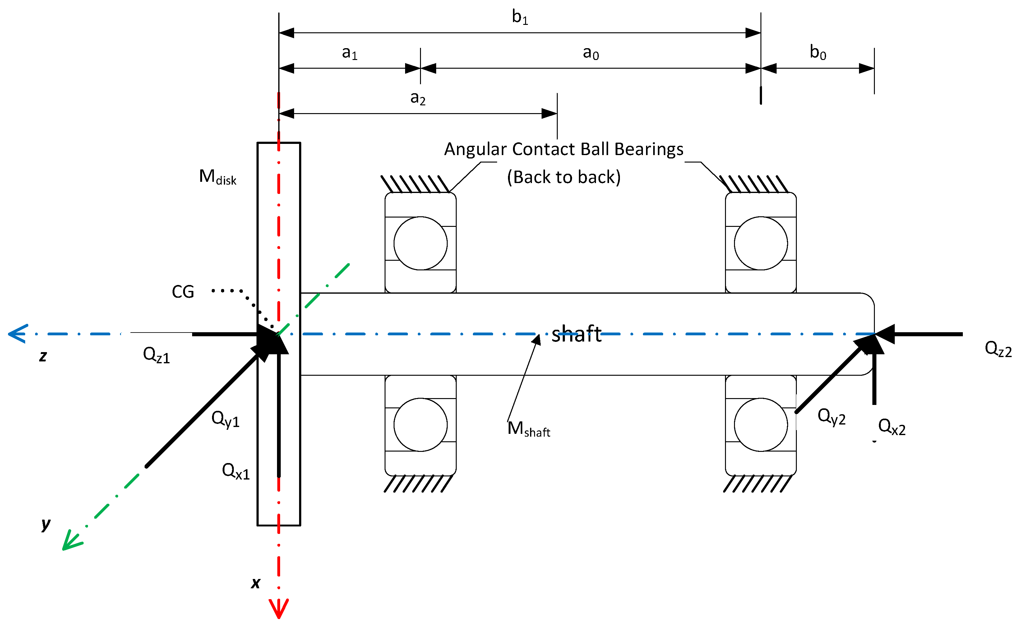
Figure 1. Motion of disc CG (Center of Gravity).
Applmech 06 00064 g001
Figure 2. Hertzian contact (a) Contact Mechanics model for bearing components, (b) Elliptic footprint.
Applmech 06 00064 g002
Figure 3. EHL contact (a) Pressure profile and oil film thickness, (b) mutual approach-deformation-oil film geometry.
Applmech 06 00064 g003
Figure 4. Stribeck diagram.
Applmech 06 00064 g004
Figure 5. Motion of disc CG.
Applmech 06 00064 g005
Figure 6. Oil film thickness for various shaft speed.
Applmech 06 00064 g006
Figure 7. Oil film thickness for different viscosity.
Applmech 06 00064 g007
Figure 8. Oil film thickness for different viscosity wrt time.
Applmech 06 00064 g008
Figure 9. Oil film thickness for different pressure-viscosity coefficient.
Applmech 06 00064 g009
Table 1. Solution Algorithm.
StepOperation
step 1Start
step 2Input system data, operating conditions, time span, material properties, and initial conditions (as listed in Table 2 and Table 3).
step 3Perform initial calculations for the parameters in the equations of motion (EoM), including contact characteristics based on the initial conditions.
step 4Solve the EoM (Equation (4)) using the Runge–Kutta method with a constant time step.
step 5Calculate the oil film thickness along the contact normal direction, mutual approach, elastic deformation, and contact force for each ball at every time step, considering shaft rotation and position of each ball by solving Equations (1)–(3) using a quasi-static approach. Apply convergence tolerance as ϵ = 1 × 10 10 for Newton–Raphson method. [Subroutine]
step 6Compute the 5-DoF positions and velocities of the disc’s center of gravity (CG).
step 7If the time vector is complete, finalize the EoM calculations; otherwise, return to Step 4.
step 8Save the results.
step 9End
Table 2. Numerical parameters used in simulations.
DiscShaft12 Ball–Angular Contact Ball Bearing (1 5 ° )
ParameterValueValueParameterValue
Diameter0.1 m0.04 mOuter Raceway Diameter0.061933 m
Length0.55 mOuter Ring Diameter0.068 m
Mass5.5 kg0Inner Ring Diameter0.04 m
Configuration Geometry a 1 = 0.05 m a 2 = 0.275 mInner Raceway Diameter0.046038 m
b 1 = 0.55m b 2 = 0.6 m
Ball Diameter0.0079375 m
Table 3. Case Studies.
Case StudySimulationShaft Speed
(RPM)
Preload
(N)
Viskozite
(Pa s)
Presure-Viskozite Coeff.
(P a 1 )
1–191[1000:500:10,000]1000.04 2.30 × 10 8
20–3023000100[0.04:0.04:0.4] 2.30 × 10 8
31–38330001000.04 1 × 10 8 : 2 × 10 9 : 2.5 × 10 8
Table 4. Oil Film Thickness wrt shaft speed.
Shaft Speed (rpm)150020003000400050006000800010,000
Inner Ring ( μ m)0.37780.45720.59880.71690.81830.91321.10571.2838
Outer Ring ( μ m)0.42800.51800.67850.81220.92721.03471.25281.4545
Table 5. Oil Film Thickness for different lubricant viscosity.
Lubricant Viscosity (Pa s)0.040.080.120.20.240.320.4
Lubricant Viscosity * (cSt)47.194.1141.2235.3288.4376.5470.6
Oil Film Thickness ( μ m)0.59880.93021.20141.65511.85472.2192.5492
* for density equal to 850 kg/m3 at 40 °C.
Disclaimer/Publisher’s Note: The statements, opinions and data contained in all publications are solely those of the individual author(s) and contributor(s) and not of MDPI and/or the editor(s). MDPI and/or the editor(s) disclaim responsibility for any injury to people or property resulting from any ideas, methods, instructions or products referred to in the content.