Article

The Mechanics of Synchronization: From Phase Modulation to Elliptical Gears with Quasi-Relativistic Properties

Leibniz Institute for Science and Mathematics Education, 24098 Kiel, Germany
Appl. Mech. 2025, 6(2), 37; https://doi.org/10.3390/applmech6020037
Submission received: 12 March 2025 / Revised: 28 April 2025 / Accepted: 13 May 2025 / Published: 16 May 2025

Abstract

:
Synchronization is a universal phenomenon in driven or coupled self-sustaining oscillators with important applications in a wide range of fields, from physics and engineering to the life sciences. The Adler–Kuramoto equation represents a reduced dynamical model of the inherent phase modulation effects. As a complement to the standard numerical approaches, the analytical solution of the underlying nonlinear dynamics is considered, giving rise to the study of kinematically equivalent elliptical gears. They highlight the cross-disciplinary relevance of mechanical systems in providing a broader and more intuitive understanding of phase modulation effects. The resulting gear model can even be extended to domains beyond classical mechanics, including quasi-relativistic kinematics and analogues of quantum phenomena.

Graphical Abstract

1. Introduction

Synchronization is a process of fundamental importance that occurs in coupled or periodically driven systems with autonomous recurrent dynamics. It is independent of the specific mechanisms that sustain the oscillations, and results in locking to a common frequency, even though the natural frequencies of the individual oscillators are different. As a cross-cutting topic, synchronization effects and their control have become relevant in many areas of science and technology. Several textbooks provide overviews of the subject from different theoretical and application-oriented perspectives [1,2,3,4,5]. A popular exposition of the subject is also available [6]. The most prominent applications range from radio-frequency electronics [7], microwave oscillators [8], lasers [9], superconducting Josephson junction devices [10], plasma physics [11] and celestial mechanics [12]. Quantum synchronization is an active field of research [13,14]. Recent innovations in quantum technology depend on the synchronizing of quantum processes and the engineering of quantum coherence. They include developments in sensing, ultra-precise metrology systems and quantum information processing and computing [15].
It is important to distinguish synchronization from resonance in driven damped oscillators, which always adapt asymptotically to an externally imposed periodic driving after transient oscillations have decayed. While linear dynamics is sufficient to describe resonance effects, synchronization involves essential nonlinearities. They underlie the transition from full synchronization (phase locking) to incomplete synchronization with periodic frequency pulling or phase modulation. Despite the variety of the underlying mechanisms, basic features can be captured by phase oscillator models. Such a reduced description was first found in electrical engineering in the context of driven vacuum tube oscillators by Adler, who derived two coupled first-order differential equations for the oscillator amplitude and phase in the limit of weak coupling. The nonlinear differential equation for the phase of a driven self-oscillator bears his name [16]. Kuramoto generalized the phase model to describe the interactions and the emergent collective behavior in many coupled phase oscillators [17]. Depending on the field, both names can be found [18].
There is a remarkable parallelism between the kinematics of elliptical gears and the nonlinear dynamics of phase modulation in synchronization, two at first sight seemingly disparate subjects. Elliptical gears, as the most basic prototype of noncircular gears, generate a special form of transmission factor between input and output rotation speeds which, with suitably chosen parameters, is identical to phase modulation effects in synchronization. Until now, this parallelism has remained unnoticed by both the gear and synchronization communities. In this contribution, as a kind of cross fertilization of theoretical approaches over disciplinary boundaries, we analyze the non-trivial theoretical connections between these two domains. Exploiting the common structures opens up intriguing links between synchronization, mechanical gears and phenomena beyond the framework of classical mechanics. In particular, the mechanical gear model of synchronization provides a new semi-classical analogue of relativistic kinematics.
This paper is structured as follows. Because of its interdisciplinary nature, it offers a self-contained overview of the fundamentals of synchronization as well as the kinematics of elliptical gears for non-specialists. The first two sections build on an earlier elementary introduction to mechanical models of synchronization phenomena and their universal importance by the author [19]. The theoretical basis of the present study is a comparison of analytical solutions of two related forms of the Adler equation. It is shown that the nonlinear phase dynamics in synchronization and the motion of elliptical gears are subject to the same type of nonlinear differential equation, called Adler-type for short. The discovery of the correspondence between the governing equations is new. It is the basis of the present new mechanical gear model of phase modulation. In addition to this classical analogue, the analysis of the common theoretical structure between different, apparently unrelated, systems provides novel perspectives beyond traditional approaches. Along these lines we show that the gear model can even be extended to domains beyond classical mechanics, including quasi-relativistic kinematics and analogues of quantum phenomena. A new semi-classical model of relativistic motion is presented. In the conclusions, we discuss some open questions of this correspondence. On a more general level, we touch upon the productive role of cross-disciplinary analogues as a source of new ideas and a research strategy for knowledge transfer between different fields of research and development.

2. Model Order Reduction in Driven Self Sustained Oscillations: The Phase Oscillator Model

We consider the synchronization of a self-sustained oscillator whose proper frequency (for simplicity we subsequently omit the term angular)   ω can be tuned and which is driven by a periodic force with a fixed drive frequency ω D . Figure 1 is a schematic overview of the effects for a driven system that is continuously tuned upwards.
The gamma factor γ = ( ω ω D ) / ω 0 describes the relative detuning with respect to a critical frequency ω 0 . In the absence of coupling, the undisturbed oscillator frequency is indicated by the dashed line. In this case, the detuning ω ω D corresponds to the beat frequency that would be obtained by a linear superposition of the two signals. If a sufficiently strong coupling is introduced by increasing the amplitude of the drive signal, the oscillator frequency changes in a nonlinear manner.
Full synchronization with ω = ω D occurs in a zone (width 2 ω 0 ) symmetrical to the frequency crossing, where the oscillator phase is fully locked to the phase of the drive. Phase locking breaks down at a critical detuning given by ω ω D = ω 0 . Frequency entrainment occurs. The oscillator frequency becomes time-dependent. It is pulled towards the drive frequency, but as the coupling strength is insufficient to achieve complete phase locking, the instantaneous oscillator frequency varies periodically. The result is a nonlinear beat signal. Typical of nonlinear beats for small detuning is a long holding period of the oscillator frequency followed by a rapid change. The resulting average beat frequency ω B is indicated by the vertical arrow. As the detuning is increased further, the oscillator frequency asymptotically approaches the undisturbed frequency.
Adler’s original treatment started from a second-order nonlinear differential equation, the driven Van der Pol equation, used in radio engineering to describe the interaction of self-sustaining electronic oscillations with an external signal. After introducing a linear approximation of the oscillator phase in the driven system at resonance, he succeeded in obtaining two coupled nonlinear equations of first-order, describing the time dependence of the oscillator amplitude and phase. Later, more rigorous theoretical treatments were given, based on averaging methods [20,21]. Here, we present a simplified derivation that neglects amplitude modulation and considers only pure phase modulation, based on the nonlinear coupling between the oscillator phase ϕ and the phase ϕ D of the drive signal. This reduces the phase dynamics to a single nonlinear first-order differential equation. In the free-running state, the oscillator frequency ω = d ϕ / d t is constant at a given detuning. The phase difference φ ( t ) = ϕ ( t ) ϕ D ( t ) evolves linearly with time according to φ t = ω ω D t . It changes at a constant rate, which defines the undisturbed beat frequency d φ U / d t = ω ω D . Coupling leads to phase locking or, outside the synchronization range, to incomplete synchronization resulting in periodic modulation of the oscillator phase or equivalently in periodic pulling the oscillator frequency ω t which now becomes time-dependent. It increases when the phase ϕ D overtakes and quasi attracts the oscillator phase ϕ , otherwise it decreases. A sinusoidal dependence on the phase difference φ is the simplest assumption to describe the periodic acceleration and deceleration of the oscillator phase. With ϵ as a measure of the forcing, the instantaneous frequency of the driven oscillator is given by
ω ( t ) = ϕ ˙ ( t ) = ω ( t ) ϵ sin ϕ t ϕ D t
Inserting ω t results in the time-dependent beat frequency d φ / d t = ω t ω D and the Adler equation for a constant drive frequency is obtained
d φ d t = ω t ω D ϵ sin φ t
By setting τ = ϵ t and γ = ω ω D / ε as the relative detuning, the equation can be made dimensionless
d φ / d τ = γ sin φ
A comparison with the frequency ω 0 of critical detuning defined in Figure 1 shows that ε = ω 0 and γ is identical to the relative detuning γ = ( ω ω D ) / ω 0 .

3. Adler-Type Equations: Analytical Solutions

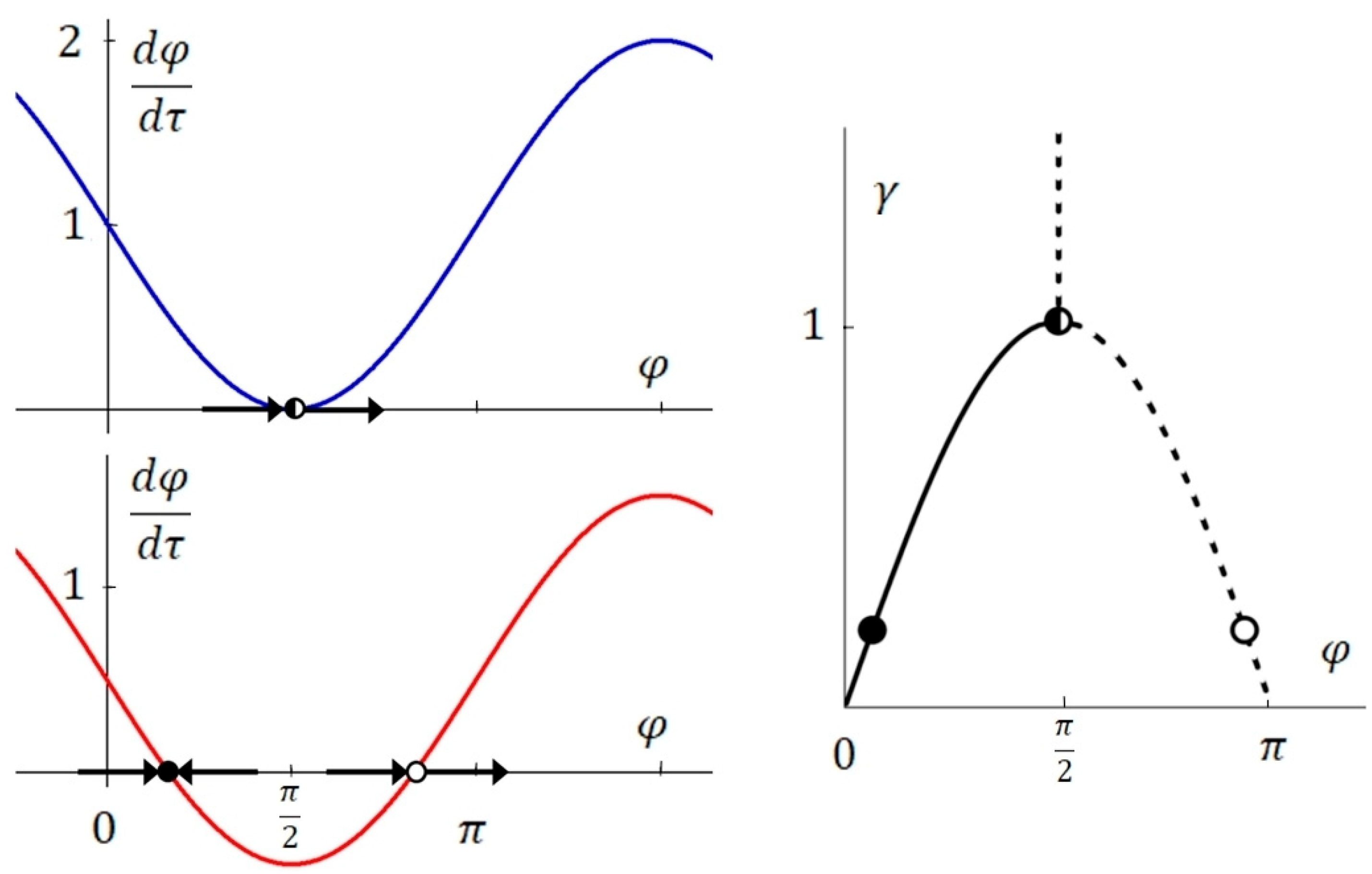
We restrict the following discussions to positive values of detuning. From the phase plane analysis of Equation (3) we see that in the synchronization zone γ < 1 , there are two fixed points with d φ / d τ = 0 (Figure 2). Due to the negative derivative, only the fixed point at φ 1 = sin 1 γ is stable, while the companion at φ 2 = π φ 1 is unstable. The breakdown of synchronization at γ = 1 is characterized by the merging of the stable and unstable fixed point. Beyond that, only running phase solutions exist with d φ / d τ > 0 . Mathematically, the transition from synchronization to periodic phase modulation is described by a saddle-node bifurcation [22]. Physically, it corresponds to a second order phase transition. The above approximation is restricted to weakly nonlinear self-oscillations and weak forcing. For stronger forcing, a jump-like first order phase transition with hysteresis behavior can occur. Even stronger forcing results in the complete suppression of the self-oscillations.
We present solutions of the Adler equation in the above original sine form. In addition, we discuss new solutions of the cosine form, as they can be directly transferred to the kinematics of antiparallelogram linkages and elliptical gears, as will be shown in Section 4 and Section 5.

3.1. Integral of the Adler Equation in the Original Form

The integral of the Adler equation after variable separation reads (the variable θ is used to discriminate the sine form from φ in the subsequent use of the cos form).
0 θ τ d θ γ sin θ = τ τ 0
Numerical integration is straightforward and can be carried out using standard spreadsheet tools [23]. It is widely used in the literature, also in combination with numerical and analytical approaches [24,25]. Adler has already given a solution in the closed form presented below. Since the integration requires a non-trivial mathematical trick based on the tangent half-angle substitution, we provide a detailed, self-contained derivation so that the interested reader can easily reproduce the calculations. With u = tan θ / 2 , d θ = 2 / 1 + u 2 d u and the substitutions sin θ 2 = u 1 + u 2 , cos θ 2 = 1 1 + u 2 , sin θ = 2 sin θ 2 cos θ 2 we obtain the integral
τ τ 0 = 0 tan θ 2 2 d u 1 + u 2 ( γ 2 u 1 + u 2 ) = 2 γ 0 tan θ 2 d u u 1 γ 2 + 1 1 γ 2
Completing the square brings the polynomial in the denominator into the integrable form d x x 2 + a 2 = 1 a tan 1 x a + c . With x = tan θ 2 1 γ , a = γ 2 1 γ and replacing the dimensionless time, the integral becomes
ω 0 ( t t 0 ) = 2 γ 2 1 tan 1 γ γ 2 1 tan θ t 2 1 γ
Solving for the phase angle gives θ t = 2 tan 1 1 γ + γ 2 1 γ tan γ 2 1 2 ω 0 ( t t 0 ) . With the condition θ 0 = 0 we arrive at t 0 = 2 γ 2 1 ω 0 tan 1 1 γ 2 1 and the final result is
θ t = 2 tan 1 1 γ + γ 2 1 γ tan γ 2 1 2 ω 0 t tan 1 1 γ 2 1

3.2. Integral of the Adler Equation in the Cos Form

As an alternative to this rather awkward expression, the cosine form of the Adler equation is considered in all the subsequent chapters. As will be shown, it also underlies elliptical gear kinematics and is the basis of the present new mechanical model of phase modulation. To distinguish it from the sine form, it is referred to as an Adler-type equation. Apart from phase shifts, which depend on the sign in the denominator, it leads to equivalent dynamics.
d φ γ ± cos φ = ω 0 t + C
For simplicity, we do not use the explicit method above, but refer instead to the tabulated solution given in standard mathematical tables ([26], #2.553):
d x A ± B cos x = 2 A 2 B 2 tan 1 A B A 2 B 2 tan x 2
For negative cos term, the phase angle with the initial condition φ 0 = 0 is
φ ( t ) = 2 tan 1 γ 1 γ 2 1 tan γ 2 1 2 ω 0 t
θ t of the original Adler equation and φ ( t ) of the Adler-type cos form describe the same dynamics up to a shift in t 0 and in the initial phase, which is not relevant in the following considerations, where only the positive or negative cosine form is used, depending on the model context. The time derivative of (10) gives the phase modulated output frequency corresponding to an instantaneous beat frequency
ω B t = d φ d t = γ 2 1 ω 0 γ + cos γ 2 1 ω 0 t
ω B varies periodically between ω m a x = γ + 1 ω 0 and ω m i n = γ 1 ω 0 . The time average ω B of the beat frequency can be read off from the argument of the cosine term in the denominator and corresponds to the geometric mean of ω m a x and ω m i n .
ω B = γ 2 1 ω 0 = ω m a x ω m i n
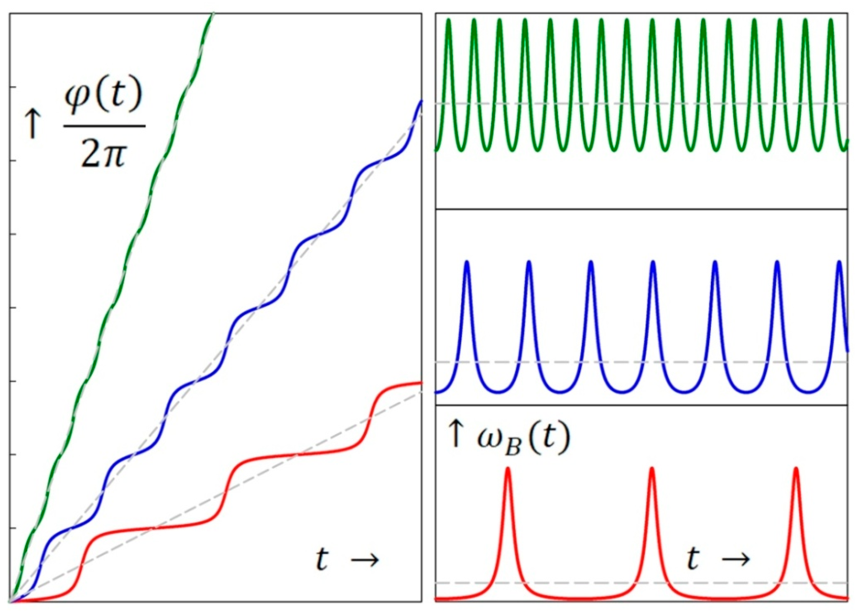
In the subsequent calculations and graphs for positive detuning, ω 0 is set to 2 π . φ t and φ ˙ t show a strongly nonlinear behavior, which prevails closely to the phase transition (Figure 3). For small overcritical detuning, there is a long holding period of the phase. ω m i n remains close to zero for most of the beat period. The rest of the cycle, up to ω m a x and back, is completed in a narrow time interval, resulting in a narrow ω B peak. The dashed lines indicate the average beat frequency ω B , dividing the beat period into a long slow and a short fast section. With increasing detuning, the asymmetry becomes smaller and the beat signals gradually approach a sinusoidal shape. This is also reflected in the spectral shape of the beat signals, which show γ -dependent decreasing amplitudes of the harmonics according to a geometric progression (see Section 4.2).

4. Phase Modulation and Elliptical Gear Kinematics: The Common Theoretical Core

Noncircular gears are highly versatile systems for producing a variable motion at the output in response to a given input. There are numerous mechanical applications, and their use in modern technology is still growing (see [27,28] for a theoretical overview). We will show that elliptical gears, as the archetypical form of noncircular gears, perfectly reproduce the γ dependence of phase modulation, provided that the elliptic parameters are chosen appropriately. This isomorphism is based on identical Adler-type differential equations. Although elliptical gear kinematics is a well-established subject in mechanical engineering, the parallelism of the governing equations with the dynamics of synchronization has not previously been described or analyzed in the literature. This provides the basis for a new mechanical model that contributes to a broader understanding of phase modulation and opens up a fresh perspective for transferring concepts between seemingly unrelated fields.
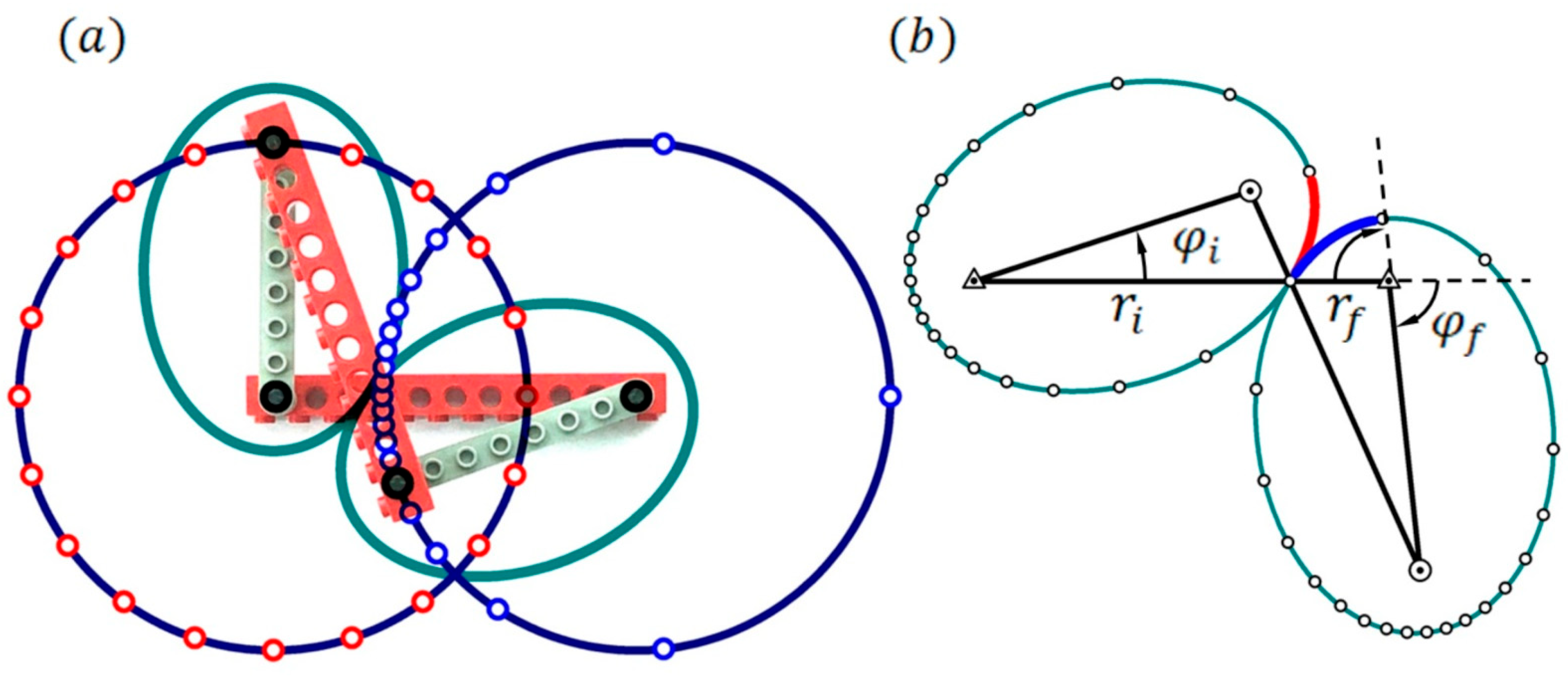
For both visualization and formal derivation, we consider the antiparallelogram linkage which exhibits equivalent kinematics. Figure 4a shows a mechanical demonstrator based on LEGO parts with graphically superposed ellipses. The joints at the ends of the two short bars are in the foci of the ellipses. The two long bars are cross-connected to the joints in the foci of the other ellipse. One of the long bars serves as a stationary horizontal rack. The short bars act as cranks. The intersection of the two long bars defines the contact point between the ellipses. The circular dynamics of the crank ends is indicated by time marks. While one crank is set to rotate uniformly, the other crank rotates at a periodically varying angular velocity. The length of the long bar is 2 a , twice the semi-major axis of the ellipse. The length of the crank is 2 c , twice the linear eccentricity. With the semi-minor axis b = a 2 c 2 , the numerical eccentricity is e = c / a = 1 b / a 2 .

4.1. Identifying an Adler-Type Differential Equation in Elliptical Gear Kinematics

The ellipses in mechanical contact and in counter rotation around the respective foci (Figure 4b) are constructed using the polar form r φ of the ellipses, which for the driving ellipse is
r φ i = a ( 1 e 2 ) 1 + e cos φ i
The constant rotation frequency of the left driving ellipse is set to the average beat frequency φ ˙ i = γ 2 1 ω 0 used in the synchronization model. The phase angle φ f of the driven ellipse is derived by combining the contact condition r i + r f = 2 a with the no-slip condition r i φ ˙ i = r f φ ˙ f for equal tangential velocities at the contact point. This gives the following differential equation
d φ f d φ i = r i r f = r i 2 a r i = 1 e 2 1 + e 2 + 2 e cos φ i = 1 e 2 2 e 1 + e 2 2 e + cos φ i
As this equation is also of the Adler type, it verifies the close relationship between the dynamics of synchronization and the kinematics of elliptical gears and allows us to represent phase modulation in a fully mechanical way using elliptical gears. For integration, we refer to the tabulated solution given in Equation (9). With A = 1 + e 2 2 e and B = + 1 , we obtain A 2 B 2 = 1 e 2 2 e and A B = 1 e 2 2 e . The phase angle of the driven ellipse is
φ f = 2 tan 1 1 e 1 + e tan φ i 2
The instantaneous frequency of the driven ellipse is   φ ˙ f = d φ f / d φ i · φ ˙ i . It varies between φ ˙ f , m a x = γ + 1 γ 1 γ 2 1 ω 0 and φ ˙ f , m i n = γ 1 γ + 1 γ 2 1 ω 0 . Analogous to Equation (12), the time average corresponds to the geometric mean of the maximum and minimum frequency.

4.2. Gear Kinematics, Phase Modulation and Comb Spectra

The modulation of φ ˙ f is much stronger than the modulation of φ ˙ in the phase model given by Equation (11), as shown by the narrower peak in Figure 5a. Fourier analysis reveals the dependence of the modulation spectra on γ . The amplitude decay of the harmonics differs between the two curves. Since ω B t is an even function, only the cosine terms contribute to the Fourier series. The amplitudes are given by the integral A n = 1 π π π ω B t cos n x d x . The tabulated solution is (cf. loc. cit. #3.613)
π π cos n x d x 1 + a cos x = 2 π 1 a 2 1 a 2 1 a n
The resulting amplitude ratio can be written as A n + 1 / A n = 1 / a 2 1 1 / a . The cos prefactor in the denominator of φ ˙ from Equation (11) is a = 1 / γ , which gives the amplitude ratio
A n + 1 / A n = γ 2 1 γ
For φ ˙ f , the prefactor is a = 2 e / 1 + e 2 = 2 / γ + 1 / γ . With 1 / a 2 1 = γ 1 / γ / 2 and 1 / a = γ + 1 / γ / 2 , the amplitude ratio becomes
A n + 1 / A n = 1 γ
Phase modulation leads to a common simple shape of comb-like spectra. Both amplitude ratios decrease accordingly in an alternating geometric series. The linear and logarithmic plots of the normalized ratio A n + 1 / A n in Figure 6 show the higher harmonic content of φ ˙ f t and the much slower decrease with n than the harmonics of φ ˙ t .

5. Gear Kinematics: Nonuniform Rack Motion from Phase Modulation

The common theoretical core of the phase model and elliptical gear kinematics justifies further investigations by exploiting the isomorphism between the two systems. An important feature of the gear model lies in its capability to transform phase modulation into the linear motion of the rack. To this end, we consider the horizontal shift of a vertical rack while the ellipses roll along the stationary sinusoidal pitch line described by their contact point, or, equivalently, by the intersection between the two crossed bars of antiparallelogram linkage.
In the following, the semi-major axis of the ellipses is set to a = γ with linear eccentricity c = 1 . This gives e = 1 / γ for the numerical eccentricity and b = γ 2 1 for the semi-minor axis (all lengths in dimensionless units). The match between the rolling ellipses and the sinusoidal pitch curve is based on the fact that the perimeter of an ellipse and the arc length of a sine curve correspond to identical elliptical integrals of the second kind [29]. Instead of this formal argument, consider an obliquely cut cylinder rolling along a flat surface. The point of contact between the elliptical cut and the surface draws a sinusoid as the cylinder rotates [30]. If a cylinder of radius b is cut at an angle of 45° relative to the center line, the edge of the cut corresponds to the given ellipses and the contact point draws the desired pitch line. With the rotation angle φ , the contact point propagates by s = b φ .
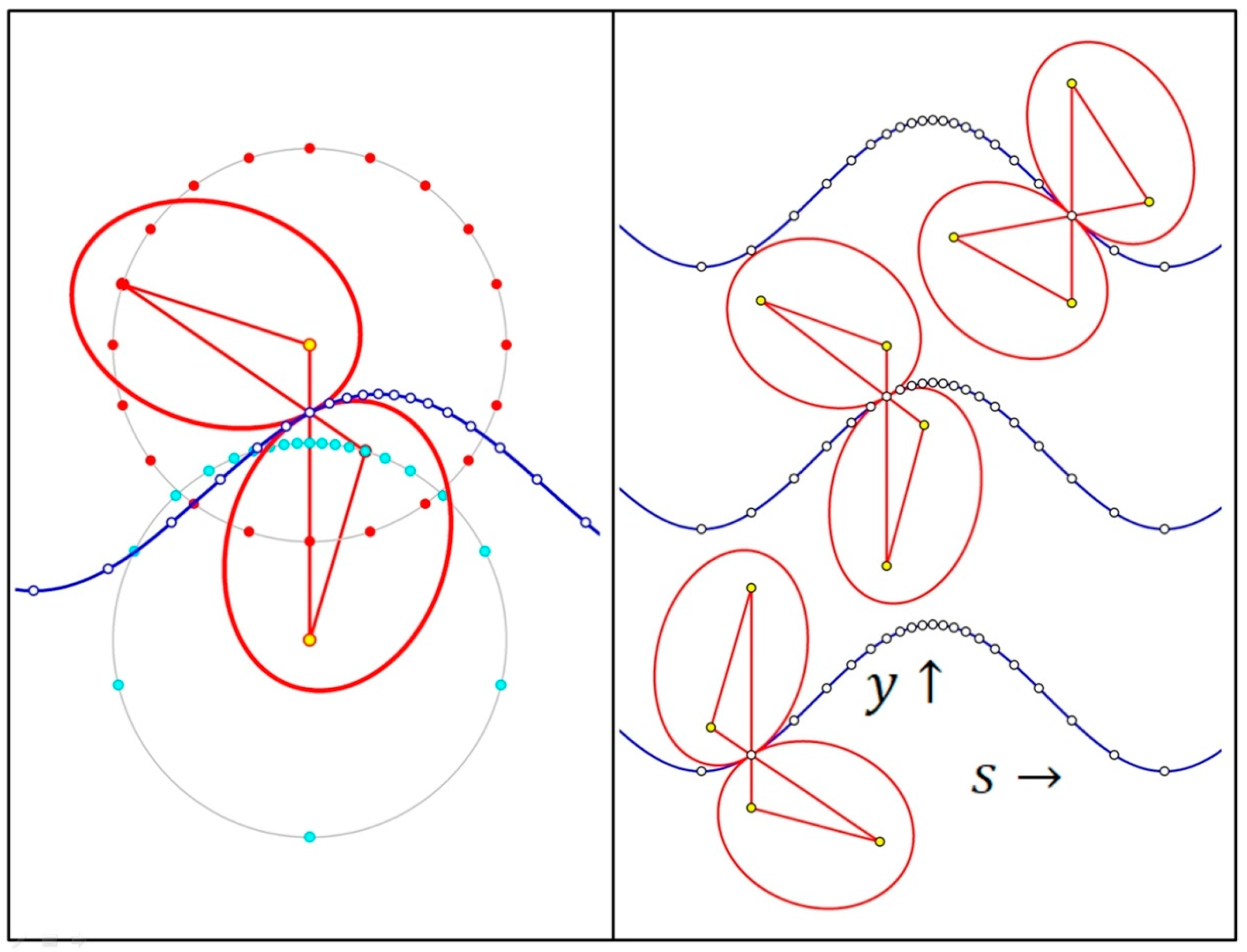
In Figure 6, the pitch line is chosen as y = γ cos φ with the minimum at s = 0 . This condition is fulfilled by the Adler-type equation with +cos in the denominator. With the resulting phase function φ = 2 tan 1 γ + 1 γ 2 1 tan φ i 2 , the rack position s = b φ is given in dimensionless units by
s = 2 γ 2 1 tan 1 γ + 1 γ 2 1 tan φ i 2
The resulting motion is shown in the snapshots of Figure 6. On the left, the different angular velocities of the ellipses are highlighted by equidistant time marks on the circles described by the rotating foci. While the driving ellipse rotates uniformly, the velocity of the driven ellipse varies periodically. The corresponding marks on the pitch line show the nonuniform horizontal propagation of the rack while maintaining its vertical orientation. The motion slows down in the first half of a period and accelerates in the second. The angular velocity of the driven ellipse varies more strongly than the rack velocity, as indicated by the time marks. Differentiation gives d s / d φ i = γ 2 1 / γ cos φ i . The derivative varies in the same way as the instantaneous frequency ω B t = d φ / d t of a periodically driven self-oscillator.
This conformity shows that phase modulation due to synchronization can be transformed into an equivalent modulation of linear propagation in the gear model. It opens up a quasi-classical perspective on relativistic motion, after incorporating appropriate extensions and correspondences. The term quasi- or semi-classical is used because, in order to serve as relativistic analogues, the models require the adaptation of concepts from special relativity and quantum mechanics. From relativity, the notion of different time scales, depending on the frame of reference, has to be integrated. The adaptation of quantum concepts refers to exploiting the correspondence between energy and momentum in quantum mechanics and frequency and wavenumber at the classical level. A brief, concise summary of the relevant notions is given before the correspondence is finalized.

6. Beyond Classical Mechanics: Quasi-Relativistic Properties of Phase Modulation and Elliptical Gear Kinematics

6.1. Summary of Relevant Relativistic and Quantum Correspondences

Special relativity distinguishes between proper time and coordinate time. Proper time, conventionally denoted by the letter τ , is the time measured by a clock moving along a timelike world line. Coordinate time is the time between two events measured by the clock of an inertial observer. To avoid confusion with t , the time used in the previous derivations, we denote it by t c o . Normally, in most textbook examples, the coordinate time is taken as given, and proper time as a function of coordinate time is calculated by the path integral over the world line of the moving clock [31]. The differential relation between proper time of a system moving at velocity v and coordinate time increments, measured by an observer at rest, who defines simultaneity, is
τ = 1 γ d t c o ,   γ = 1 1 v 2 / c 2 = 1 1 β 2   .
The Lorentz factor γ depends on β , the quotient of v and the speed of light c . Here, we have the opposite situation. The time variable t used in the previous relations corresponds to proper time, which belongs to the system whose dynamics it describes. We will therefore keep the letter t for proper time in the following calculations. Starting from the proper time interval t τ , we have to derive the coordinate time interval t c o , i.e., t c o = γ t , in order to describe the motion from the coordinate frame of an external observer at rest.
From the wave–particle dualism in quantum physics we know that the rest mass m of elementary particles is linked to an internal oscillation at the Compton frequency. Equating E 0 = m c 2 and E 0 = ω 0 ( reduced Planck constant h ) gives the frequency ω 0 = m c 2 / of a particle at rest. We denote it by ω 0 to relate it to the present models, where it describes the critical detuning at which the resting state becomes unstable and the running phase solution sets in. The Compton wavelength of the particle is λ C = 2 π c / ω 0 or, written in the standard form λ C = h / m c .
Another relevant quantity from quantum physics is the de Broglie wavelength λ B , which is connected to the momentum p by λ B = h / p . For particles with rest mass the momentum is p = E 2 E 0 2 / c . As only one dimensional motion is considered, the vector notation is omitted. They obey the relativistic dispersion relation.
E = E 0 2 + p c 2
The dispersion relation describes how the total energy E = γ E 0 is divided between the rest energy E 0 = ω 0 and the momentum p c . It encodes relativistic invariance: all observers, regardless of their reference frame, will agree on the rest mass m = E 0 / c 2 of a particle. With ω = γ ω 0 and the wavenumber k = p / , the equivalent relation for frequency is
ω = ω 0 2 + k c 2
The relativistic momentum of a particle is p = γ m v = β γ m c . This gives the wavenumber k = β γ m c / . The phase of a propagating wave is φ = k x ω t . For particles with rest mass, there are two relevant velocities, the phase velocity v p h = ω / k = c / β and the group velocity v g r = d ω / d k = β c . The latter represents the particle velocity v . Particles with zero rest mass, such as photons, have no dispersion in a vacuum. In this case, v = c and E = p c .
Against this theoretical background, the quasi-relativistic properties of the phase model can now be finalized. The γ factor, which describes the relative detuning in the phase model, corresponds to the Lorentz factor in the relativistic interpretation. γ can be regarded as an energy boost. γ = 1 is necessary to obtain a particle at rest; setting the particle in motion requires γ > 1 . The energy excess, the difference between total energy E and rest energy E 0 , is the kinetic energy of the system E k i n = ( γ 1 ) E 0 .
With the relativistic constants, Equation (22) becomes γ = 1 + β γ 2 and   ω B = γ 2 1 ω 0 can be written as ω B = β γ ω 0 . With ω 0 = m c 2 / we finally obtain
ω B / c = γ m v
In this way, the relativistic momentum p = γ m v can be related to the average beat frequency. The formal identity between ω B / c and the relativistic momentum can also be seen by comparing the relativistic dispersion hyperbola for ω in Figure 7a with the hyperbolic shape of the synchronization diagram for positive detuning in Figure 1 after swapping the coordinate axes.
So far, the analogy is only formal. Since the phase model describes the synchronization of a stationary oscillator, spatial propagation is not involved. It requires further substantiation in terms of a plausible physical model to account for synchronization effects in a moving system. The frequency ω D of the driving field does not appear explicitly in the beat formula, but only as a reference level in the definition of relative detuning. It acts virtually in the background. From a field-theoretic point of view, this background can be regarded as a vacuum field that sets the reference level against which the rest energy is defined. Lorentz invariance of the vacuum ensures that a particle interacts with the same field regardless of the particle’s speed. Therefore, the reference point for γ does not change. An energy boost γ > 1 sets the particle in motion. Synchronization provides a self-regulating mechanism to achieve a dynamic balance between total energy, rest energy and momentum in accordance with relativistic dispersion. In a way, the sync model extends the concept of self-organization to the dynamics of relativistic particles. The conformity of the semi-classical model with the Heisenberg’s uncertainty principle from quantum mechanics is discussed below. Table 1 summarizes the correspondence between the classical and the relativistic description.

6.2. Quasi-Relativistic Properties of Rack Propagation in the Gear Model

We adopt a one-map two-clock approach to represent the spacetime trajectories. It is based on using the distance x in a common map or coordinate frame, and two time scales [32]. Coordinate time is derived from proper time as described above and t c o is used to assign time to events that are simultaneous in the coordinate frame.
In dimensionless units, the propagation of the phase-modulated system in proper time t is assumed to be x = φ ( t ) / ω 0 , with φ given by Equation (10). An assignment of coordinate time to this nonuniform trajectory requires caution. Due to the modulation of ω B , the same amount of energy is fed into and taken out of the system once per period, resulting in periodic acceleration and deceleration. An accelerated clock will show a smaller elapsed time compared to the readings of the inertial clock, given by the system with average momentum ω B / c . The latter propagates with the coordinate velocity v = β c and its coordinate time is t c o = γ t . A direct comparison of the clock readings requires simultaneous events: both clocks must be at the same point in space and time in order to assign the correct coordinate time to the accelerated system.
Figure 7b compares the spacetime trajectories in the coordinate frame. The accelerated motion plotted as a function of t c o is an approximation because the time assignments are correct only at certain discrete events and not throughout the entire curve. Both systems meet twice per period, where their spacetime trajectories cross. It is only at these events that the clock readings in both systems can be directly compared and the true coordinate time of the accelerated system is known. From the perspective of an inertial observer in uniform motion, the accelerated system completes two round trips per period. In one half it lags behind, in the other, it leads the observer’s motion. The situation is analogous to the twin paradox, or rather the twin puzzle, where the clock of the twin in the round trip is found to have run slower than the companion’s, when both compare their clocks after reunion. For this reason, accelerated trajectories are only indicated by dashes, because the true coordinate time beyond the crossings is not known. This would require an appropriate definition of simultaneity in distant systems, e.g., by using radar time and radar distance, which is beyond the scope of this introduction.
The models highlight another important, though not so widely known, concept from relativistic kinematics. The coordinate distance covered in the proper time interval t is x = v γ t . The term v γ is known as the proper velocity w = x / t = β γ c . The graphs of the accelerated motion show that, irrespective of γ , the same distance is covered in one beat period T B = 2 π / β γ ω 0 . This unit length, given by x = β γ c T B = 2 π c / ω 0 , is the Compton λ C wavelength of the particle. The beat period written as a function of the de Broglie wavelength λ B is T B = λ B / c . This gives a simple interpretation of relativistic propagation: a particle takes a time proportional to its de Broglie wavelength to travel a distance corresponding to its Compton wavelength. In terms of the two wavelengths involved, the proper velocity of the particle is simply
w = λ c λ b c
Proper velocity is defined by the quotient of the displacement x measured in the coordinate frame and the proper time difference t τ measured in the moving system. This mixed derivative may seem somewhat unusual. In full, proper velocity is a relativistic 4 vector. The 3 derivatives of the coordinates with respect to proper time describe the spatial speed and the fourth component is related to the speed of time. Proper velocity corresponds to momentum per mass. While Equation (24) refers to the scale of elementary particles, proper velocity is equally relevant on the macroscopic scale.
Proper velocity is an important concept in spaceflight, from rocket dynamics to timekeeping, navigation and communication [33,34]. Different to coordinate velocity, it is not bounded, and it may appear that the propagation exceeds the speed of light, which of course is not possible in reality. It is the speed that an astronaut experiences by observing the passage of external objects, even though his coordinate velocity is subluminal. Proper velocity is useful for describing interstellar travel at extreme, but subluminal speeds, so that astronauts could theoretically reach distant galaxies within their lifetimes.
The apparent superluminal propagation does not violate relativity theory, since the coordinate velocity given by v = x / t c o = β c does not exceed the speed of light. Proper velocities can be composed in the classical way, analogous to the addition of mechanical momentum in Newtonian physics. This additive property of proper velocity comes closer to our classical experience than the relativistic addition of velocities. Thus, the underlying one map-two clock approach allows us to explain relativistic kinematics and dynamics in a largely intuitive way.
With this theoretical embedding, the present gear model illustrates proper velocity in a fully classical framework. However, there is a price to pay: we have to accept the notion of two different timescales. Only proper time is available in the model, and coordinate time must be inferred theoretically to obtain a complete description. Despite these problems, it provides a fascinating, multi-faceted playground for exploring abstract relativistic concepts through applied mechanics using concrete and tangible systems.

6.3. Conformity with Quantum Uncertainty

Finally, it should be noted that the consistency of applying classical-quantum correspondences to the present models can be checked against Heisenberg’s uncertainty principle. The periodically modulated momentum leads to a trajectory that oscillates relative to uniform propagation. We give an estimate of the uncertainties involved. The distance x = λ C / 2 = π c / ω 0 covered in half a beat period is used as an estimate of the uncertainty in position. The momentum variation between p m a x = γ + 1 m c and p m i n = γ 1 m c is 2 m c . This gives an estimated momentum uncertainty p = 2 ω 0 / c . The resulting uncertainty product is
x p h
This corresponds to the lower bound of the uncertainty relation in Heisenberg’s original formulation. It gives the correct order of magnitude of the uncertainty according to the accepted formal version x p / 2 .
The uncertainty relation is relevant for a correct interpretation of the trajectories. The full line is the trajectory of the center of mass propagating with average momentum as described by classical mechanics. The Ehrenfest theorem applies in the present case of a free particle: the quantum mechanical expectation value of the position propagates according to the classical equations. However, an actual position measurement will find the particle within a hose that includes the dashed oscillatory trajectory.

7. Conclusions and Outlook: The Heuristic Role of Mechanical Models Between Intuition and Abstraction

It remains to consider briefly, why the phase model shows quasi-relativistic properties. Basically, we have used two ingredients to bridge the classical notion of synchronization with quantum and with relativistic concepts: the Planck relation E = ω and the Einstein relation E = m c 2 . There is a close connection with de Broglie’s idea of generalizing the wave–particle dualism of photons to all material particles, which finally gave rise to the matter wave concept and the wave wave–particle duality [35,36]. This groundbreaking discovery marked the beginning of modern quantum physics 100 years ago. De Broglie introduced matter waves by considering the synchrony between the periodic processes within a quantum particle, the ‘particle clock’ in de Broglie’s terminology, and the associated phase wave. He used arguments from relativistic kinematics to describe phase coherence between these two periodic processes, which transform differently in a moving system. From this, he finally derived the wavelength of matter waves that bears his name.
His original idea of an underlying ‘phase harmony’ corresponds to the relativistic invariance of the phase of the wave function. The present models replace de Broglie’s purely kinematic argumentation with a dynamical approach. In short, phase modulation represents a nonlinear dynamical process that is consistent with relativistic dispersion and is equally capable of maintaining synchrony. However, nonlinearity comes at a price. It is more difficult to build up wave packets in a nonlinear model. This is why we have concentrated on the particle aspect and on modulating the particle momentum, to preserve synchrony between the internal periodic processes of the propagating particle and the associated phase wave.
However, this is only a preliminary outline of why the phase model of synchronization and its interpretation in terms of propagation driven by elliptical gears can serve as an analogue of relativistic particle motion. A full appreciation of this new example of quasi-classical dynamics as a quantum analogue requires further in-depth theoretical analysis. For a review of established analogies, see [37,38]. As the model includes acceleration, it also touches upon analogue gravity and spacetime models. This is currently a highly active field, where laboratory simulations of quantum gravity phenomena are exploited using different material platforms [39,40].
We conclude with a brief outlook on the heuristic role of models and mechanisms. The development of science and technology shows a progression towards increasing abstraction that transcends naive mechanistic views. Modern physics no longer provides us with an intuitive picture of the underlying theoretical concepts and processes at a fundamental level. Nevertheless, mechanisms and visualization play an important role in theoretical development, in making sense of abstract theoretical concepts and in conceiving applications. The underlying creative processes can be described by the productive interplay of abstract, systematic, conceptual knowledge and concrete, experiential, model-based knowledge [41]. The development of electromagnetism is exemplary in this respect. Maxwell’s initial heuristic approaches to formalize Faraday’s findings were based on mechanical ideas, in particular using differential gear mechanisms for induction or molecular vortex models to describe electromagnetic fields [42]. He eventually abandoned these heuristic mechanical constructions in favor of a consistent, abstract mathematical theory. This resulted in the Maxwell equations, a first fully relativistic theoretical framework, which culminated in the discovery of electromagnetic waves.
In this article, we have adopted a kind of reverse engineering approach to visualize field theoretic models of relativistic particles by constructing mechanical models. The kinematics of mechanical linkages and gears have been analyzed to reveal the complete isomorphism with the dynamics of phase modulation. These systems can help to clarify important aspects of synchronization, a universal, cross-cutting concept that applies to the phenomena of self-organization and coherence on the classical as well as the quantum level. The scope of the models encompasses analogies and correspondences with relativistic and quantum concepts, including the relativistic energy momentum relation, proper velocity and the consistency with quantum uncertainty. It embeds them in a familiar classical context without neglecting the gap to our classical world of experience. It demonstrates that concrete models and mechanisms, despite their limitations in providing a complete coherent picture, play an important role in exploring, clarifying and applying abstract theoretical concepts. They are essential for achieving a broader understanding and play a significant role in the unfolding of creative processes in science and technology.

Funding

This research received no external funding.

Institutional Review Board Statement

Not applicable.

Informed Consent Statement

Not applicable.

Data Availability Statement

The original contributions presented in this study are included in the article. Further inquiries can be directed to the corresponding author.

Acknowledgments

I want to thank the anonymous reviewers for helpful comments.

Conflicts of Interest

The author declares no conflict of interest.

References

  1. Pikovsky, A.; Rosenblum, M.; Kurths, J. Synchronization: A Universal Concept in Nonlinear Sciences; Cambridge University Press: Cambridge, UK, 2001. [Google Scholar]
  2. Balanov, A.; Janson, N.; Postnov, D.; Sosnovtseva, O. Synchronization: From Simple to Complex; Springer: Berlin/Heidelberg, Germany, 2009. [Google Scholar]
  3. Strogatz, S. Sync: The Emerging Science of Spontaneous Order; Hyperion: New York, NY, USA, 2003. [Google Scholar]
  4. Winfree, A.T. The Geometry of Biological Time; Springer: New York, NY, USA, 1980; Volume 2. [Google Scholar]
  5. Gros, C. Complex and Adaptive Dynamical Systems, 4th ed.; Springer: Berlin, Germany, 2017. [Google Scholar]
  6. Strogatz, S.H. Sync: How Order Emerges from Chaos in the Universe, Nature, and Daily Life; Hachette: New York, NY, USA, 2012. [Google Scholar]
  7. Razavi, B. A study of injection locking and pulling in oscillators. IEEE J. Solid-State Circuits 2004, 39, 1415–1424. [Google Scholar] [CrossRef]
  8. Kurokawa, K. Injection locking of microwave solid-state oscillators. Proc. IEEE 1973, 61, 1386–1410. [Google Scholar] [CrossRef]
  9. Siegman, A.E. Lasers; University Science Books: Herndon, VA, USA, 1986. [Google Scholar]
  10. Barone, A.; Paterno, G. Physics and Applications of the Josephson Effect; Wiley: Hoboken, NJ, USA, 1982. [Google Scholar]
  11. Klinger, T.; Piel, A.; Seddighi, F.; Wilke, C. Van der Pol dynamics of ionization waves. Phys. Lett. A 1993, 182, 312–318. [Google Scholar] [CrossRef]
  12. Ershkov, S.; Leshchenko, D. On the stability of Laplace resonance for Galilean moons (Io, Europa, Ganymede). An. Acad. Bras. Cienc. 2021, 93, e20201016. [Google Scholar] [CrossRef] [PubMed]
  13. Walter, S.; Nunnenkamp, A.; Bruder, C. Quantum synchronization of a driven self-sustained oscillator. Phys. Rev. Lett. 2014, 112, 094102. [Google Scholar] [CrossRef]
  14. Walter, S.; Nunnenkamp, A.; Bruder, C. Quantum synchronization of two Van der Pol oscillators. Ann. Phys. 2015, 527, 131–138. [Google Scholar] [CrossRef]
  15. Vaidya, G.M.; Jäger, S.B.; Shankar, A. Quantum synchronization and dissipative quantum sensing. Phys. Rev. A 2025, 111, 012410. [Google Scholar] [CrossRef]
  16. Adler, R. A study of locking phenomena in oscillators. Proc. IRE 1946, 34, 351–357, reprinted in Proc. IEEE 1973, 61, 1380–1385. [Google Scholar] [CrossRef]
  17. Kuramoto, Y. Self-entrainment of a population of coupled nonlinear oscillators. In International Symposium on Mathematical Problems in Theoretical Physics; Araki, H., Ed.; Lecture Notes Physics; Springer: Berlin/Heidelberg, Germany, 1975; Volume 39, pp. 420–423. [Google Scholar]
  18. Acebrón, J.A.; Spigler, R. The remote control and beyond: The legacy of Robert Adler. SIAM News 2007, 40, 1–2. [Google Scholar]
  19. Euler, M. Universal synchronization: Acoustic experiments, the phase oscillator model and mechanical analogues. Eur. J. Phys. 2024, 45, 023003. [Google Scholar] [CrossRef]
  20. Krylov, N.M.; Bogoliubov, N.N. Introduction to Non-Linear Mechanics; Princeton University Press: Princeton, NJ, USA, 1950. [Google Scholar]
  21. Hänggi, P.; Riseborough, P. Dynamics of nonlinear dissipative oscillators. Am. J. Phys. 1983, 51, 347–352. [Google Scholar] [CrossRef]
  22. Kuznetsov, Y.A. Saddle-node bifurcation. Scholarpedia 2006, 1, 1859. [Google Scholar] [CrossRef]
  23. Liengme, B.V. Modeling Physics with Microsoft Excel; Morgan & Claypool: San Rafael, CA, USA, 2014. [Google Scholar]
  24. Buonomo, A.; Schiavo, A.L. Remarks on the Adler’s equation. In Proceedings of the 2015 European Conference on Circuit Theory and Design (ECCTD), Trondheim, Norway, 24–26 August 2015; pp. 1–4. [Google Scholar]
  25. De Luca, R.; Giordano, A.; D’Acunto, I. Mechanical analog of an over-damped Josephson junction. Eur. J. Phys. 2015, 36, 055042. [Google Scholar] [CrossRef]
  26. Gradshteyn, I.S.; Ryzhik, I.M. Table of Integrals, Series, and Products; Academic Press: Cambridge, MA, USA, 2014. [Google Scholar]
  27. Litvin, F.L.; Fuentes-Aznar, A.; Gonzalez-Perez, I.; Hayasaka, K. Noncircular Gears: Design and Generation; Cambridge University Press: New York, NY, USA, 2009. [Google Scholar]
  28. Gupta, K.; Jain, N.K.; Laubscher, R. Advanced Gear Manufacturing and Finishing: Classical and Modern Processes; Academic Press: London, UK, 2017. [Google Scholar]
  29. Jameson, G.J.O. Inequalities for the perimeter of an ellipse. Math. Gaz. 2014, 98, 227–234. [Google Scholar] [CrossRef]
  30. Apostol, T.M.; Mnatsakanian, M.A. Unwrapping curves from cylinders and cones. Am. Math. Mon. 2007, 114, 388–416. [Google Scholar] [CrossRef]
  31. Rindler, W. Relativity: Special, General, and Cosmological; OUP Oxford: Oxford, UK, 2006. [Google Scholar]
  32. Fraundorf, P. A one-map two-clock approach to teaching relativity in introductory physics. arXiv 1996, arXiv:9611. [Google Scholar]
  33. Walter, U. Relativistic rocket and space flight. Acta Astronaut. 2006, 59, 453–461. [Google Scholar] [CrossRef]
  34. Messerschmitt, D.G. Relativistic timekeeping, motion, and gravity in distributed systems. Proc. IEEE 2017, 105, 1511–1573. [Google Scholar] [CrossRef]
  35. de Broglie, L. Ondes et quanta. Comptes Rendus Acad. Sci. 1923, 177, 507–510. [Google Scholar]
  36. de Broglie, L. Recherches sur la théorie des quanta. Ann. Phys. 1925, 3, 22–128. [Google Scholar] [CrossRef]
  37. Dragoman, D.; Dragoman, M. Quantum-Classical Analogies; Springer Science & Business Media: Berlin/Heidelberg, Germany, 2004. [Google Scholar]
  38. Park, D. Classical Dynamics and Its Quantum Analogues; Springer Science & Business Media: Berlin/Heidelberg, Germany, 2012. [Google Scholar]
  39. Jacquet, M.J.; Weinfurtner, S.; König, F. The next generation of analogue gravity experiments. Philos. Trans. R. Soc. A 2020, 378, 20190239. [Google Scholar] [CrossRef]
  40. Almeida, C.R.; Jacquet, M.J. Analogue gravity and the Hawking effect: Historical perspective and literature review. Eur. Phys. J. H 2023, 48, 15. [Google Scholar] [CrossRef]
  41. Euler, M. The mechanics of creative cognition: Orchestrating the productive interplay of procedural and conceptual knowledge in STEM education. Proc. Singap. Natl. Acad. Sci. 2021, 15, 105–117. [Google Scholar] [CrossRef]
  42. Bucci, O.M. From Electromagnetism to the electromagnetic field: The genesis of Maxwell’s equations [Historical Corner]. IEEE Antennas Propag. Mag. 2014, 56, 299–307. [Google Scholar] [CrossRef]
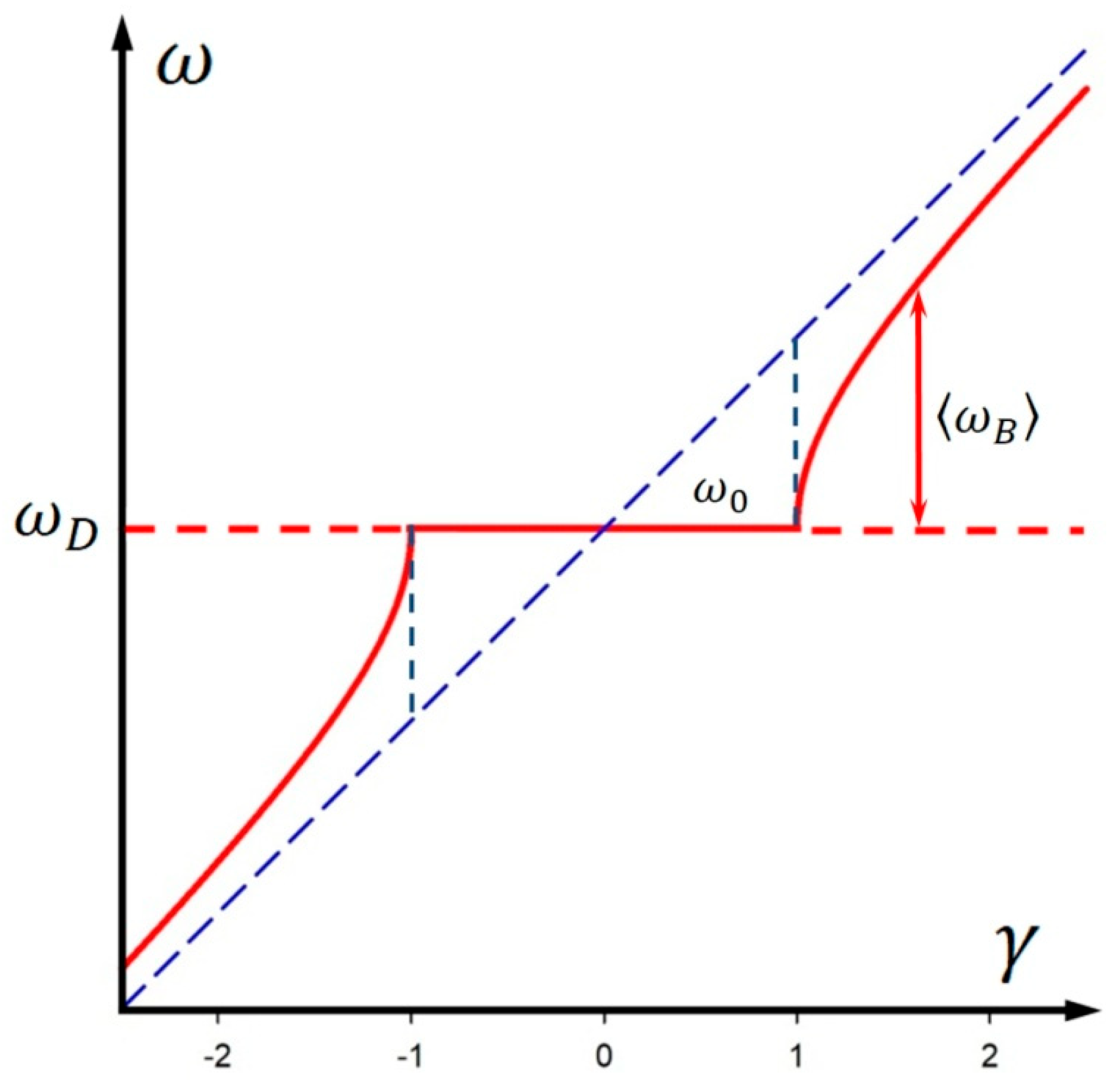
Figure 1. Schematic sketch of synchronization and frequency entrainment of a self-oscillator driven by a constant frequency ω D (red dashed line). Without coupling, the self-oscillator frequency ω is linearly tuned upwards (blue dashed line). With coupling, ω changes nonlinearly. The resulting average oscillator frequency corresponds to the red solid line. If the detuning is below the critical limit given by ω 0 < ω ω D , full synchronization occurs. The abscissa is scaled in units of relative detuning, defined by the gamma factor γ = ( ω ω D ) / ω 0 .
Applmech 06 00037 g001
Figure 2. Phase plane analysis of d φ / d τ = γ sin φ for γ = 1 / 2 (red line) and γ = 1 (blue line) with fixed points at d φ / d τ = 0 . The stability of the fixed points is indicated by the arrows (full circle: stable, open circle: unstable). The bifurcation diagram shows the merging of the stable and unstable branch at γ = 1 (from [19] with permission).
Applmech 06 00037 g002
Figure 3. Time dependence of the phase φ and the instantaneous beat frequency ω B ( t ) = φ ˙ for γ 1 = 1.02 (red), γ 2 = 1.12 (blue) and γ 3 = 1.8 (green). The phase increases in steps of 2 π . The ω B ( t ) scale ranges from 0 to 3 ω 0 . The dashed lines in the ω B plots are the time average ω B of the beat frequency. In the phase plot, they show the linear rise of the average phase φ A V = ω B t (from [19] with permission).
Applmech 06 00037 g003
Figure 4. (a) Lego model of the antiparallelogram linkage with superposed co-rotating ellipses. The two circles describe the uniform rotation of the left grey input crank and the nonuniform rotation of the cross-connected output crank. The small circles indicate equidistant time steps. (b) Position of the linkage and the ellipses after the first time step starting with all bars in a horizontal position. The highlighted sections show the elliptical arcs of equal length covered during this interval.
Applmech 06 00037 g004
Figure 5. (a) Comparison of φ ˙ t (red line) and φ ˙ f ( t ) (blue line) for γ = 1.1 . (b) Linear plot of the normalized amplitude ratio A n + 1 / A n .  (c) Logarithmic plot of the normalized amplitude ratio.
Applmech 06 00037 g005
Figure 6. Snapshots of the rotating ellipses for γ = 1.5 . The rack maintains its vertical orientation and propagates horizontally while the ellipses roll along the blue pitch line y = γ cos ( s / b ) . The circles indicate 20 equidistant time steps per period. The upper driving ellipse rotates uniformly.
Applmech 06 00037 g006
Figure 7. (a) Relativistic dispersion and ω ( k ) -vectors for three γ values. From left to right: γ 1 = 1.02 , γ 2 = 1.2 , γ 3 = 1.8 . (b) Corresponding spacetime plots in the coordinate frame for a particle with constant average momentum (straight lines) and periodically modulated momentum (dashed lines). The circles at the intersections mark the events where the coordinate time of the accelerated system is known. As γ increases, the trajectories approach the light cone limit at 45°. The ω ( k ) vectors and the inertial trajectories have the same slope, since tan α = p c E = k c γ ω 0 = x c t c o = β .
Applmech 06 00037 g007
Table 1. Summary of relevant correspondences.
Phase Modulation and Elliptical Gear ModelRelativistic Correspondence
relative detuning γ = ( ω ω D ) / ω 0
with ω D 0 as reference level
Lorentz factor γ = 1 / 1 v 2 / c 2
critical detuning ω 0 particle at rest with E 0 = ω 0
average beat frequency ω B = γ 2 1 ω 0 average momentum p = ω B / c = γ m v
dispersion relation ω = ω 0 2 + k c 2 dispersion relation E = E 0 2 + p c 2
one timescale t = t p r o p two timescales: t p r o p and t c o o r d
Disclaimer/Publisher’s Note: The statements, opinions and data contained in all publications are solely those of the individual author(s) and contributor(s) and not of MDPI and/or the editor(s). MDPI and/or the editor(s) disclaim responsibility for any injury to people or property resulting from any ideas, methods, instructions or products referred to in the content.