1. Introduction
Thick plates such as ship hull specimens can be successfully formed with FFP. One of the most important advantages of FFP is not using mechanical tools and replacing them with flames. In this way, the problems caused by the use of mechanical tools, along with their significant costs, are eliminated. In FFP, the plate is irradiated with the help of a flame, and when thermal energy enters the plate, a thermal gradient distribution (temperature gradient field) is created along it. After passing the flame torch, the cooling stage starts and plastic strains are induced in the plate due to the difference in cooling rate and heat conduction through the material, which leads to forming in the plate. In recent years, little research has been carried out regarding the process of forming metal plates by flame, especially the forming of complex parts. Ueda et al. [
1] obtained a simple equation to calculate the curvature of flame-formed parts using computer-aided process planning. Also, in another study, Ueda et al. [
2] presented an equation obtained with the help of the finite element method and used this equation to calculate the strains created in the plate metals after FFP. Their results showed that the presented model can predict the curvature with good accuracy. Other researchers [
3,
4,
5,
6] tried to present the mechanism of the FFP and conduct comprehensive research in the field of FFP. Jang and Moon [
7] established an algorithm to calculate the curvature of the plates. Their algorithm predicted the curvatures in the FFP. In the presented algorithm, the position of some points along the irradiation lines was checked before and after heating, and by comparing the position of these points, the amount of curvature was calculated. The method they presented was only suitable for radiation along straight lines and not for other radiation patterns. Moshaiov and Vorus [
4] and Moshaiov and Shin [
8] studied the bending mechanism in the FFP and presented a model based on strains perpendicular to the irradiation lines.
Several studies have been conducted on the prediction of deformation due to heating. Yu et al. [
9] investigated the bending of a flat plate under heating by a moving source. An analytical solution and a finite element simulation were carried out as part of their study. The bending angle was measured with good accuracy, and by establishing the results, an algorithm for the fabrication of doubly curved surfaces was expressed [
10]. Xu et al. [
11] proposed a mathematical model for forming parts by plasma arc. The temperature field was calculated by considering the heat source as a Gaussian distribution. The results show that forming is easier for materials with smaller heat transfer coefficients, and that the scanning speed is a critical forming parameter. Seong et al. [
12] developed a 3D inverse solution for the flame forming process. The bending angle and shrinkage were obtained by an algorithm using geometrical parameters and forming parameters, and a saddle-shaped surface was produced. Also, similar research was performed to find the relationship between the bending angle and the radius of the curvature of the deformed curve shape in the bending of the plate by torch [
13]. Hemmati and Shin [
14] developed an analytical solution for finding the temperature and heat flux during the forming of plates by flame bending process. The heat flux distribution was assumed to be varied according to Gaussian distribution. The results of line heating show that the proposed model can predict the temperature distribution with good accuracy. The model is adopted according to the flame parameters (torch–plate gap distance, scanning speed, heat convection coefficient). The study only focused on thermal analysis, and structural–thermal coupled analysis was not carried out. Maolu et al. [
15] focused on the effect of the number of heating passes in the forming of 1Cr18Ni9Ti sheets by using a plasma arc heat source. The results show that the plate bending angle increases linearly with an increasing number of plasma arc heating passes, and at a low number of passes, by repeating the heat irradiation, the rate of bending slows down and decreases.
Bae et al. [
16] studied the forming of plates by oxy-propane flame forming. The line heat flux of the flame is modeled as the Gaussian distribution in the finite element model. By using statistical approaches, a semi-analytical formula was developed between the bending angle and process parameters (heat flux, scanning speed, and plate thickness). In another piece of research, Bae et al. [
17] investigated the deformation of plates during cutting by oxy-ethylene flame. In this way, a finite element simulation was carried out by modeling the heat source, and the size of the heat-affected zone was measured using a statistical technique related to the deformation of the cutting edge. A similar study was conducted by Bae et al. [
18], with the heat source being a high-frequency induction source. Biswas et al. [
19] studied the deformation of plates during the oxyacetylene flame forming. A 3D finite element solution was carried out and the deflection of the plate in single-pass line heating and double-pass line heating along longitudinal and transverse directions was compared. The results show that the deformation of the plate decreases by increasing the plate thickness, and the deformation of double-pass flame irradiation is almost 1.92 to 2.13 times more than the single-pass. The oxyacetylene flame can reach temperatures up to 3500 °C.
Safari and Joudaki [
20] proposed a spiral irradiating scheme to fabricate a saddle-shaped surface. The effects of the number of irradiation passes and spiral path pitches on the magnitude of deformations of flame-formed saddle-shaped surfaces were investigated. Safari and Farzin [
21] compared two irradiating schemes: spiral and combined patterns in the fabrication of bowl-shaped surfaces by FFP. They found that the investigation of the curvature and symmetry of fabricated specimens by two irradiating patterns proves that the spiral path is a better method than the combined irradiating pattern. Similar research has been conducted by Safari [
22]. Further, a comprehensive review was published on different aspects of plate bending by line heating by Biplab [
23].
The literature survey and the experience of the authors in the field of forming by heat source, and especially forming by laser beam, shows that most of the studies focus on bending and forming by laser beam. However, the main imperfection in laser bending and laser forming is the ability to form thick plates. Increasing the thickness requires higher laser power. The laser beam diameter is narrow, and due to high laser heat flux, usually the plate melts instead of forming. One solution for this is using gaseous heat sources like an oxyacetylene flame. Finding suitable irradiating patterns for forming complex parts from simple plates has become an important challenge in recent years due to their complexities. It should be noted that in recent years, most researchers have focused on the 2D forming of parts, and there is important interest in the field of 3D flame forming. Based on this, in this article, the experimental investigation of the forming of saddle-shaped surfaces from a flat plate using the FFP has been investigated. For this purpose, the spiral irradiation pattern has been used to form the flat plate and produce saddle-shaped surfaces. To carry out a comprehensive investigation of the effect of process variables on the magnitude of curvatures of the fabricated specimens, the design of experiment (DOE) method and statistical analysis were used. For this purpose, the effects of input parameters, including PSP, RSC, and NIP, on the amount of curvature of the flame-formed saddle-shaped specimens as the output have been studied.
2. Materials and Methods
The experiments were carried out on mild steel (AISI 1010 low-carbon steel) material. The chemical composition of the mild steel was 0.094% C, 0.48%Mn, 0.38% Si, 0.05%P, and 0.06%S. The initial plate had a 12 mm thickness and was cut to 400 mm (length) × 300 mm (width) dimensions. The thickness is an important parameter on the flame forming and the curvature radius relates to the inertia of the workpiece in bending and the plate dimensions. As can be seen, the thickness is low compared to the width and length. FFP is performed with an oxyacetylene flame torch, and moving the torch along the spiral path is done with the support of a 2-axis CNC table. The oxyacetylene flame is prepared by mixing the acetylene (20 L per minute flow rate and 1 bar gas pressure) and oxygen (70 L per minute flow rate and 7 bar gas pressure). The distance between the torch and the top surface of the plate was 45 mm. The feed speed of the torch was 20 mm/s. The thick plate was shown while flame forming took place (
Figure 1).
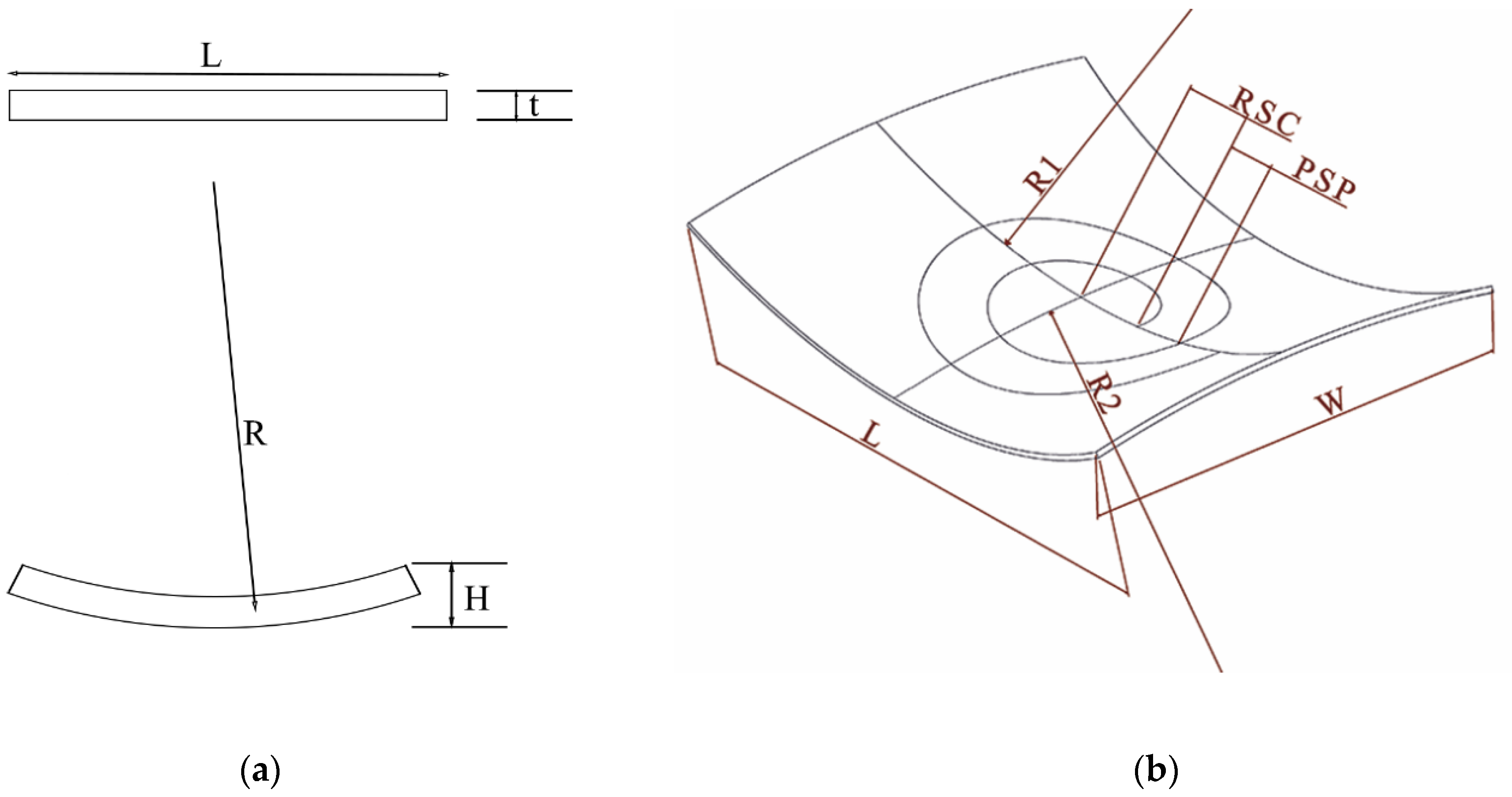
In this paper, the vertical displacement of sample point H in the formed specimens (
Figure 2) is used to evaluate the value of the curvature radius of the saddle-shaped specimens fabricated by FFP. The sample point H is the intersection of the anticlastic curvatures of the saddle-shaped surface, and its vertical displacement is important in assessing the amount of curvature. The vertical displacement of sample point H is measured by way of a coordinate measuring machine (CMM, Easson ENC-565) with measurement resolutions equal to 0.5 µm. Equations (1) and (2) show the relation between the vertical displacement of sample point H and the curvature radius of the plate. L, W, and t are the length, width, and thickness of the plate; in this case, two curvature radii, R1 and R2, exist in different planes of the plate. The R2 radius is defined in the perpendicular plane. Equations (1) and (2) are calculated implicitly (numerically) by MATLAB R2019b software. It is worth noting that the radius of curvature is influenced by the dimensions of the sample, especially the distance from the edge of the sample; in the current study, the radius of curvature is calculated at the center of the plate.
To find the best operating conditions for fabricating a saddle-shaped surface with a maximum value of curvatures, the response surface methodology (RSM) is implemented, and twenty experiments have been designed accordingly. The selected levels for each input parameter, such as the pitch of the spiral path (PSP), the radius of the starting circle (RSC), and the number of irradiation passes (NIP) are presented in
Table 1. In addition,
Table 2 shows the list of experiments according to the RSM method. It should be noted that in all experiments, the spiral path’s endpoint is fixed. The spiral pattern ends at a 105 mm radius.
3. Results and Discussion
The results of analysis of variance (ANOVA) for fabricated saddle specimens with FFP are presented in
Table 3. The ANOVA was performed using Minitab 2021 software. It should be noted that in the ANOVA results, a P-value less than 0.05 meant that the variable had a significant and important effect on the output response, i.e., the curvature of the saddle specimen. Hence, it can be concluded from
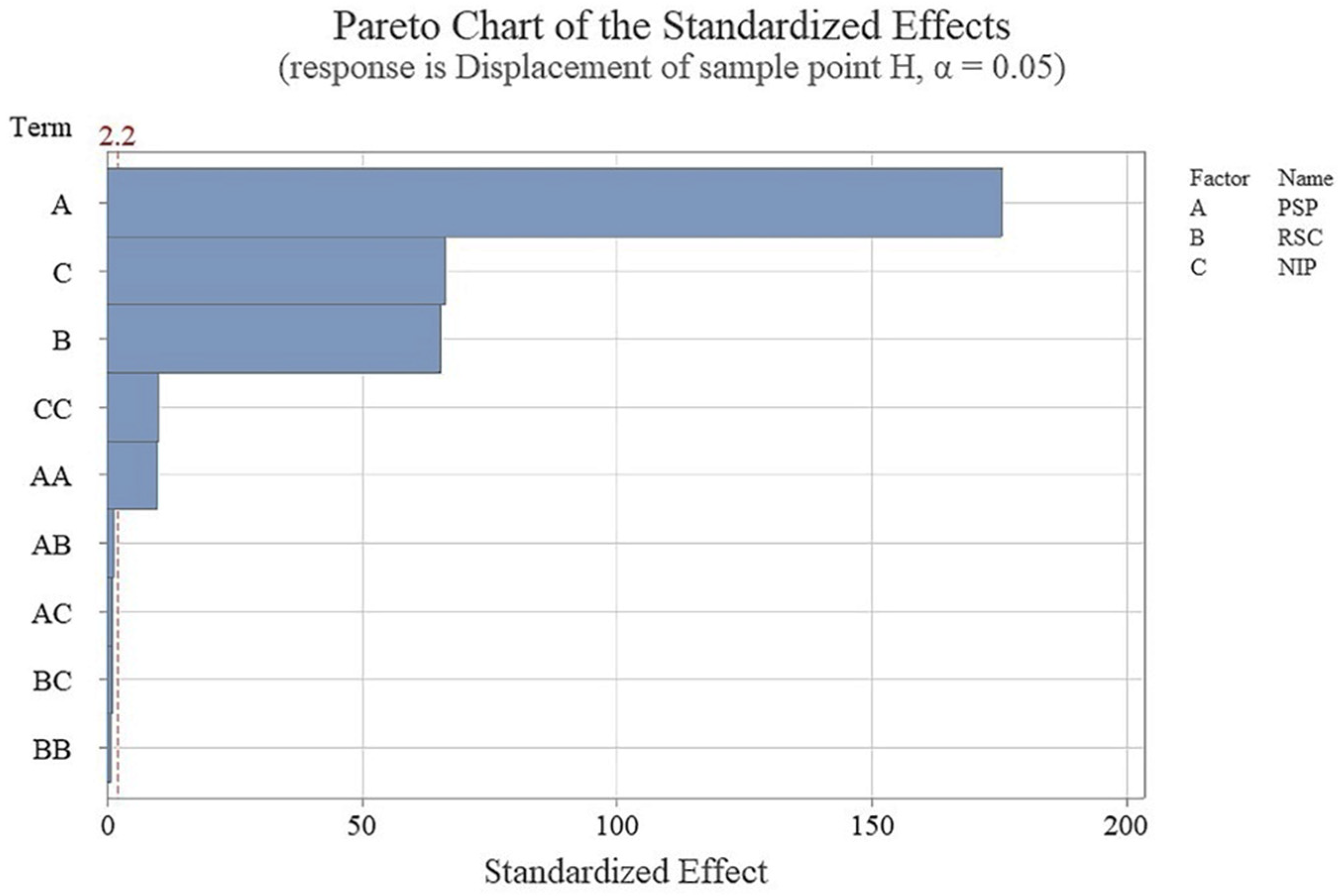
Table 3 that all input parameters, such as PSP, RSC, and NIP, have significant effects on the magnitude of curvature of the flame-formed saddle-shaped specimens. In addition, PSP and NIP squares significantly affect saddle specimens’ curvatures. However, the square of RSC and the interactions of input parameters have no important effects on the curvatures of saddle parts.
Figure 3 shows the Pareto chart plotted from the results of
Table 3. The quality of curve fitting in the statistical analysis is evaluated by coefficient of determination (R-Sq). It was found that in this research, the R-Sq was 99.97%, proving the excellent quality of the curve fitting of the employed model.
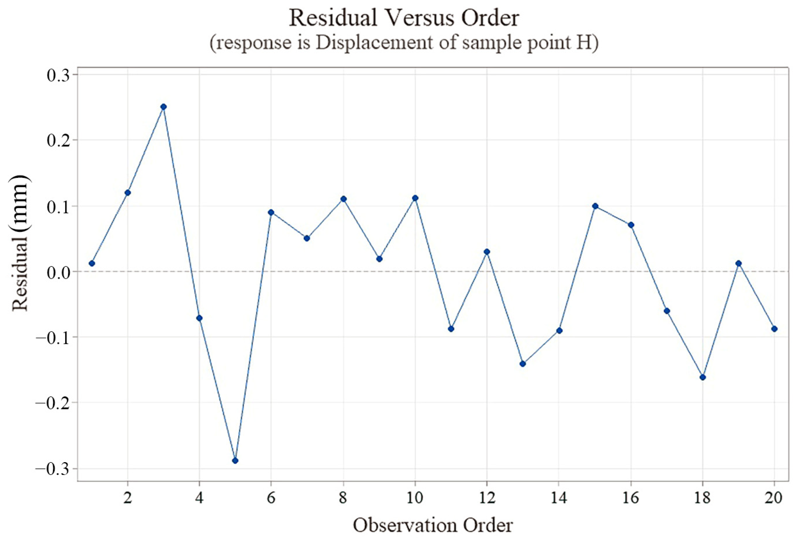
The residual plot (
Figure 4) shows the difference between the experimental observations and the predicted regression model (difference between blue dots and horizontal axis) for the curvature of flame-formed saddle specimens. The distribution of residuals is acceptable and does not obey any pattern. Furthermore, the regression equation between input variables (PSP, RSC, and NIP) and output response (displacement of sample point H) is presented in Equation (3). The curvature radii R1 and R2 are derived similarly (Equations (4) and (5)). Equations (3)–(5) are obtained from fitting a quadratic equation to the results and predicting the output parameter with an acceptable error. The coefficient of determination (R
2) shows the quality of curve fitting, and in this study, the coefficient of determination (R
2) is 99.95, 99.01, and 99.03%, respectively, for Equations (3)–(5), which shows the goodness of fit.
It should be noted that using ANOVA analysis, the effect of each input parameter on the response can be determined independently from other input parameters. Hence, in
Figure 5, the main effect plots for the curvature of the saddle parts are shown. It is concluded from
Figure 5 that the curvature of the saddle specimen, i.e., the displacement of sample point H, is decreased by increasing the PSP. The distance between the start and end points of the spiral is constant, so by increasing the spiral pitch, the length of the beam radiation on the plate decreases. Hence, the amount of thermal energy entered into the plate is also reduced, and as a result, the areas of plastic deformation created on the plate are also reduced. However, the final curvature of the saddle parts produced with the FFP is also reduced. In addition, the curvature of the saddle specimen increases with an increase in the RSC. The point that should be noted is that the deformations that occur in the central areas of the plate always create more stiffness than the areas further away in the plate. Deformation of the central areas causes more rigidity in the plate, so subsequent deformations caused by heating other areas have less effect on the final deformation of the plate. By increasing the RSC, fewer areas from the center of the plate are heated, and then the initial stiffness of the plate decreases; therefore, the deformation of the outer areas of the plate causes an increase in the final deformation of the plate. Also, the curvature of the saddle specimen increases with the increase in NIP. The reason for this is that by increasing the NIP, the plate received more thermal energy, and more plastic deformation zones were created, increasing the curvature of the produced saddle parts.
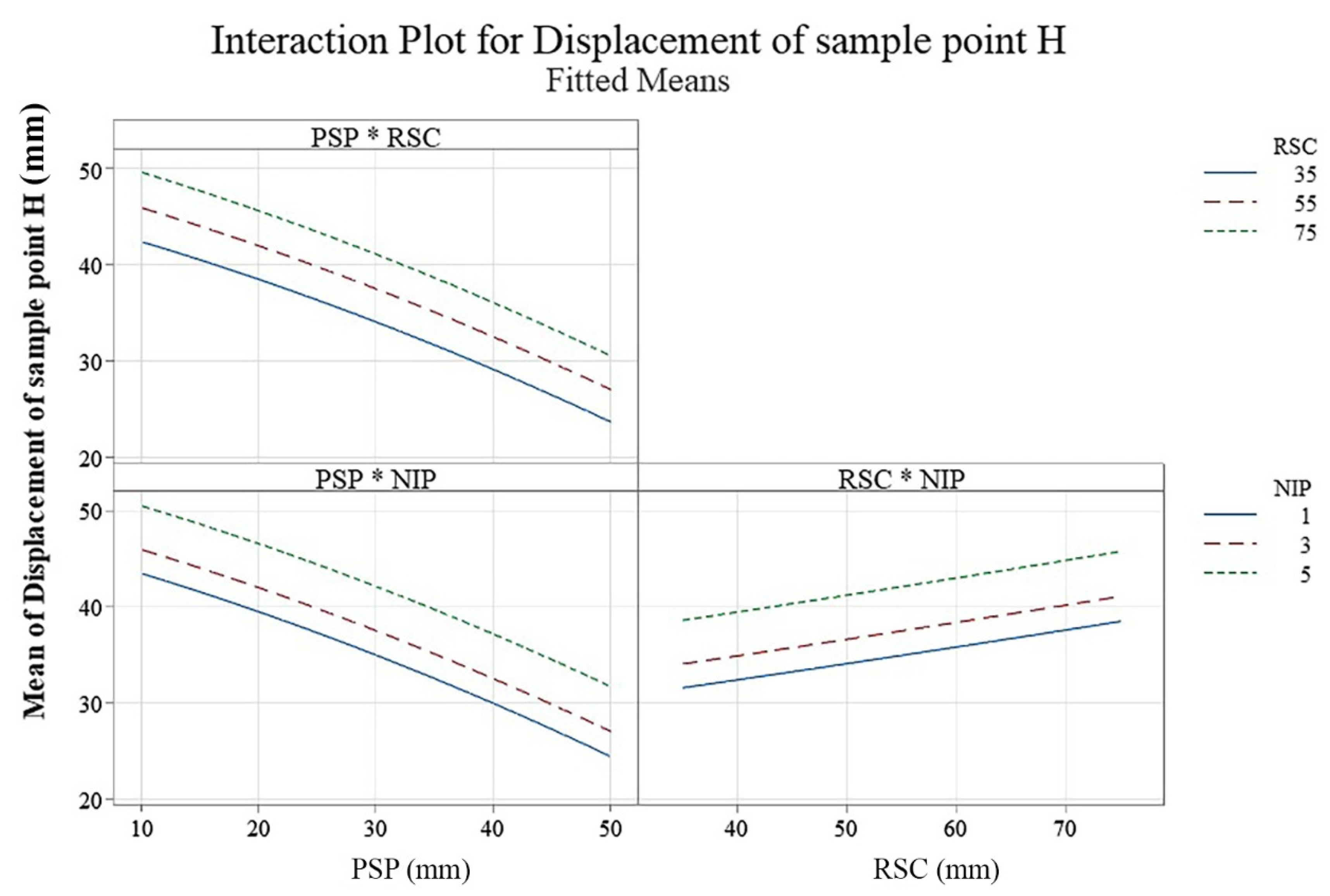
Figure 6 shows the interaction plot of the displacement of sample point H. As can be seen, all of the curves of parameter interaction are parallel and do not intersect. By comparing
Figure 5 and
Figure 6, it can be concluded that the influence of the PSP parameter dominates the effect of RSC and NIP.
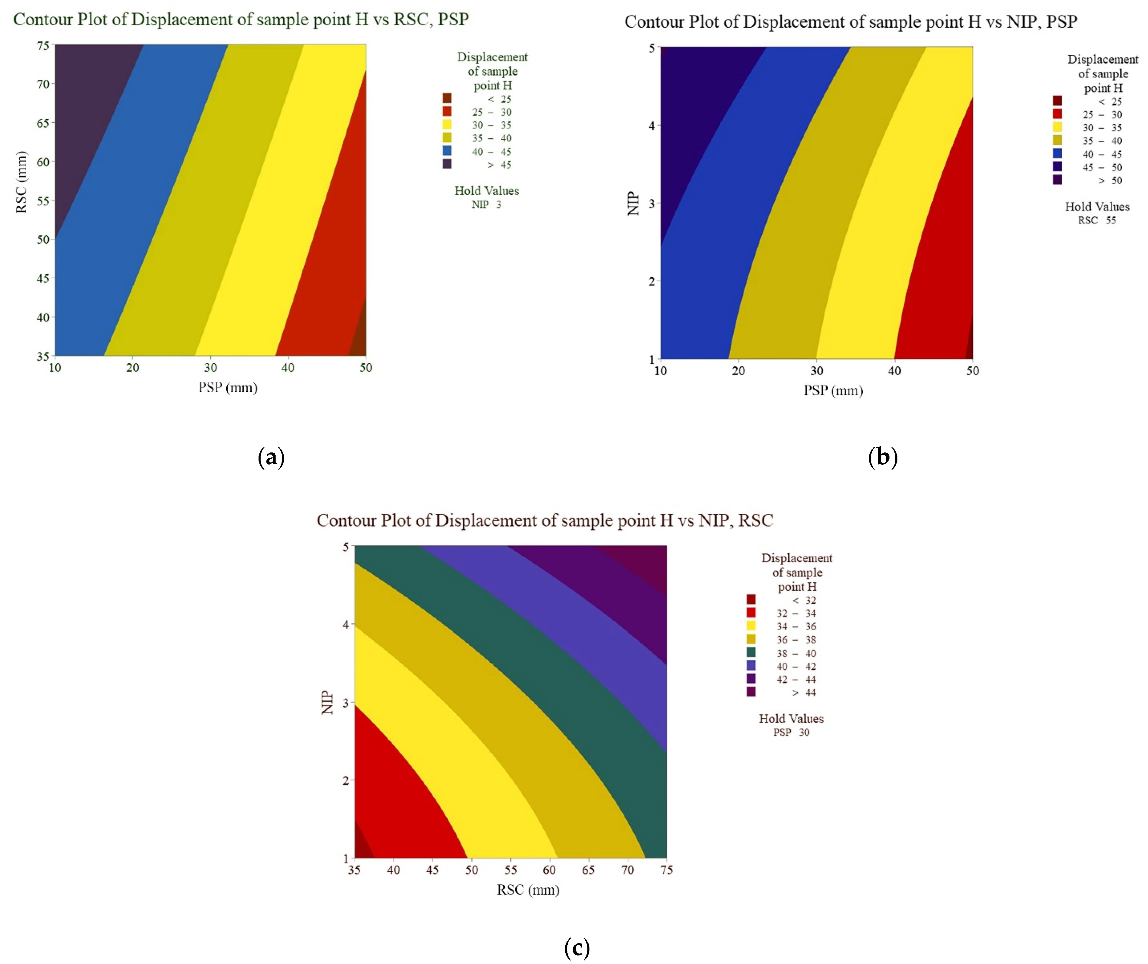
The contour plots of variations in sample point H versus the variations in the input parameters of the process are shown in
Figure 7. As can be expected from
Figure 6, the contour plot of parameters increases or decreases monotonically. It should be noted that the interactions of process variables are determined to be uninfluencing parameters from the Pareto chart (
Figure 3).
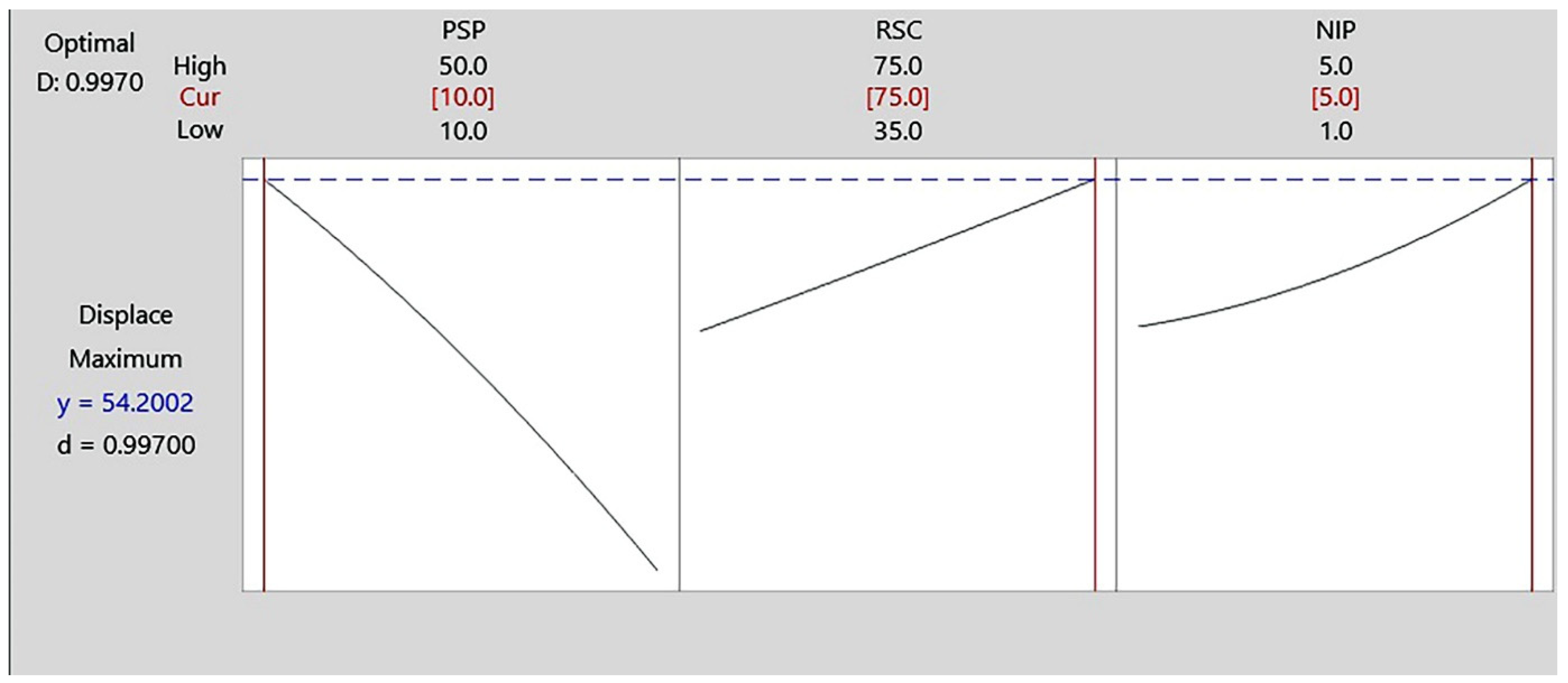
Figure 8 shows the optimized state of the displacement of sample point H. The saddle-shaped surface has two curvatures in perpendicular planes, and the curvatures increase by maximizing the displacement of sample point H. The optimization results show that by selecting PSP as 10 mm, RSC as 75 mm, and five irradiation passes, the displacement of sample point H will be maximized (54.2 mm).
As mentioned previously, the curvature radius relates to the inertia of the workpiece in bending and the plate dimensions. However, the dimension is not solely the influencing parameter. The concentration of heat on the surface of the plate is more important. A higher curvature radius will be obtained by concentrating the heat energy on a narrower width (higher heat flux) due to a higher thermal gradient mechanism (TGM).
Table 4 shows the calculated curvature radius of the formed plates along the two directions of length and width of the plate. The results are obtained by the implicit calculation of curvature radius according to Eq. 1 and Equation (2).


