Article

Dimensional Accuracy and Mechanical Characterization of Inconel 625 Components in Atomic Diffusion Additive Manufacturing

by
Tobias Rosnitschek
*,
Catharina Stierle
,
Christian Orgeldinger
,
Armin Seynstahl
,
Bettina Alber-Laukant
and
Stephan Tremmel
Engineering Design and CAD, University of Bayreuth, Universitätsstraße 30, 95447 Bayreuth, Germany
*
Author to whom correspondence should be addressed.
Appl. Mech. 2024, 5(2), 376-390; https://doi.org/10.3390/applmech5020022
Submission received: 30 March 2024 / Revised: 10 May 2024 / Accepted: 23 May 2024 / Published: 28 May 2024

Abstract

:
Metal material additive manufacturing (MEAM) has risen in interest in the last five years as an alternative to powder bed processes. MEAM is promising for generating shelled components with defined infill structures, making it very interesting for lightweight engineering. Atomic Diffusion Additive Manufacturing (ADAM) is a filament-based MEAM process patented by Markforged Inc. that provides a closed process chain from preprocessing to the final sintering of printed green parts. This study focuses on Inconel 625, which is of high interest in the aerospace industry, and assesses its dimensional accuracy and tensile properties regarding different print orientations and solid, triangular, and gyroid infill structures. The results showed that neither the dimensional accuracy nor the sintering shrinkage was significantly influenced by the printing orientation or the infill structure. In the context of lightweight engineering, the infill structures proved beneficial, especially within the elastic region. Generally, triangular infill patterns resulted in higher stiffness, while gyroids led to more ductile specimens. A mass-related evaluation of tensile testing elucidates that with the aid of the infill structures, weight savings of 40% resulted in mechanical performance decreasing by only 20% on average, proving its high potential for lightweight design.

1. Introduction

A wide variety of processes for the additive manufacturing (AM) of polymer, metal, or ceramic components have been developed over the past few decades [1]. Powder bed fusion with a market share in 2020 of 54%, including selective laser sintering, selective laser melting, electron beam melting, direct metal laser sintering, direct energy deposition, and material/binder jetting, are the most widely utilized metal AM techniques [2], as depicted in Table 1.
Currently, powder bed-based processes are primarily used for metallic components. These have several disadvantages. On the one hand, the price of the powder and the equipment is very high due to the use of powerful lasers or the vacuum technology required for electron beam applications; on the other hand, the manufactured parts have a welded microstructure, which usually requires additional heat treatment [1]. Metal filament printing—with a market share of 10% in 2020 according to [2]—via extrusion, in combination with the post-treatment steps of debinding and sintering, is an economical and straightforward-to-operate alternative. Thermoplastics, ceramics, metals, hybrid materials, and reinforced composites like metal–polymer composites can all be manufactured using extrusion additive manufacturing (EAM). In metal EAM (MEAM), the production of a feedstock made of metallic powder and binder is the initial stage. After the printing process, the binder is removed during two post-treatment steps, debinding and sintering, thus creating the final metal component [2].
Especially in times where product development needs to be operated in a more sustainable manner regarding the availability of resources and the life cycle of products, MEAM shows great potential [3]. Further, due to the extrusion process, shelled parts with defined infill structures are favored in MEAM, which is accompanied by reduced material use and printing times and the possibility to tailor the components’ effective properties. These shelled structures with infill patterns enhance the lightweight design potential significantly [4] and are also known in nature, e.g., in human bones, for adapting their effective mechanical properties to their specific purposes [5].
In current research, studies investigating Atomic Diffusion Additive Manufacturing (ADAM), an MEAM process patented by Markforged Inc. (Boston, MA, USA), are predominately on stainless steel 17–4 PH [6,7,8,9,10,11,12,13,14,15,16,17], mostly with a focus on mechanical properties. Besides 17–4 PH, few studies investigate copper filaments [18,19,20], while research on other materials such as coldwork tool steel D2 [21] and Inconel 625 [22] is very scarce. Thus, our work focuses on Inconel 625, which, due to its prominence in the aerospace industry, is of high interest for lightweight engineering applications. The influence of infill patterns on the printability, accuracy, and mechanical properties of polymers has been extensively studied, for instance in [23,24,25]. Nevertheless, due to the additional steps of debinding and sintering, those results cannot be simply transferred to ADAM parts. Kiswanto et al. investigated the influence of a triangular infill structure on the surface roughness and impact toughness of ADAM-produced Inconel 625 [22], but no studies evaluating the influence of infill structures on the shrinking behavior or tensile properties of ADAM-fabricated Inconel 625 have been conducted yet. Further, most studies focus on solid-filled specimens, which is a shortcoming as shelled and structure-filled parts are very prominent in EAM in general and can hardly be manufactured with powder bed AM processes.
Thus, it is this study’s objective to assess the commercial ADAM process chain for Inconel 625 components with different infill structures regarding process robustness, dimensional accuracy, surface roughness, and effective tensile properties. Further, a mass-related evaluation of the tensile test allows for assessing the current state of the art of lightweight engineering performance of Inconel 625 components in MEAM.

1.1. Influence of Design and Printing Parameters on Mechanical Properties in MEAM

ADAM is an MEAM process that uses a feedstock composed of metallic powder and a paraffin-based binder. As the flowchart in Figure 1 shows, the filament is deposited layer-wise and is referred to as the green part. In the next step, the main part of the binder is removed in the debinding process, leaving behind a carbon backbone that ensures the integrity of the now-obtained brown part. These residues are eliminated in the early stages of the sintering process after the first sinter necks have formed. After the sintering process has been finished, a full metal part with a linear shrinkage of about 13–20% is obtained [8,26,27,28].
The shrinkage in MEAM is an effect of the sintering process, whereas its anisotropy is affected by the printing direction and its value is controlled by the binding agent content [29]. Accordingly, the remaining anisotropy in the microstructure is caused by pores and not by the grains’ shape or size. In this regard, the parts differ heavily from powder bed additive manufacturing metal parts whose anisotropic properties arise from the welded microstructure.
Studies for MEAM in general have shown that different printing parameters, e.g., build orientation, type of infill, infill degree, and layer thickness, influence the mechanical properties of the final part [30]. As already known from polymer EAM, thinner layer thickness leads to better mechanical properties due to the decrease in voids between deposited paths, resulting in a lower surface roughness. These effects were investigated by Kurose et al., who compared the mechanical properties of 316 L stainless steel parts with layer thicknesses of 0.1 mm and 0.3 mm [31]. For both build orientations, flatwise and upright, their results show the specimens with a layer thickness of 0.1 mm withstanding a higher tensile strength. Also, the strain break was higher for the samples with a 0.1 mm layer thickness. In addition, when printing with a 0.3 mm layer thickness, voids around the outside lines of the internal structures were observed, which were not present in the samples with a layer thickness of 0.1 mm [31]. Thus, the better mechanical performance of smaller layer thicknesses can be attributed to a better linkage between the shell and the infill structure.
In general, the type and degree of infill influence the occurrence of printing defects, affecting the mechanical properties of the parts, which has been extensively studied for thermoplastic polymers. Khan et al. investigated the effect of four different infill patterns in EAM-printed PLA parts: rectilinear, concentric, honeycomb, and Hilbert Curve [23]. Their data show that rectilinear and honeycomb infills provide the maximum strain. The rectilinear infill pattern also achieved the highest Young’s modulus and yield strength. Dezaki et al. compared the tensile strength of FDM-manufactured PLA parts with concentric, triangular, and zig-zag infills [24]. They achieved the highest load-bearing specimens with a concentric tensile load infill due to those patterns providing lower void fractions than other infill types. Also, the results of Dezaki et al. show an increase in tensile strength with increasing density. Parab et al. also investigated the optimal infill pattern for FDM PLA parts [25]. They tested triangular, gyroid, and rectilinear infill patterns at different infill degrees. Their results showed that a triangular infill can withstand greater yield loads than the gyroid and rectilinear infill patterns. They also state that gyroid infill shows mostly isotropic properties, hence being useful for parts that are subjected to multiple loading directions.
In contrast, the research on MEAM in general is very scarce, particularly regarding parts, contrary to the results obtained for thermoplastics. Damon et al., for instance, state that the yield strength of their SS 316 L samples is not significantly affected by the build orientation (flatwise: 155 ± 6 MPa; upright: 165 ± 12 MPa), because the pore channels of both their build orientations are oriented at 45° to the load direction [32]. Tosto et al. analyzed the influence of the building orientation on the tensile properties of SS 316 L [33]. Their results show that flatwise-printed specimens display higher values for tensile strength. The difference in tensile properties between flatwise- and upright-printed samples was explained by voids that ran perpendicular to the testing direction.
Regarding different infill structures, Gonzalez-Gutierrez et al. focused on the effects of different infill patterns in copper parts. They found that rectilinear and diagonal patterns do not influence the flexural properties of the specimens significantly [34]. While the influence of the infill structure density was shown to be significant for the effective mechanical properties [3], studies comparing different infill structures for MEAM or ADAM in general are still missing.

1.2. Sinter Shrinkage of MEAM Parts

During sintering, pores in the part are removed, leading to a full, dense metal part due to growth and adhesion amongst the metal particles, thus causing the part to shrink. Sintering is the intrinsic deformation mechanism of MEAM and consists of at least six different diffusion-controlled [35] mass transport mechanisms, contributing to the bonding between the metal particles by forming so-called sinter necks. This shrinkage does not occur equally in all directions but depends on the orientation of the part [35,36,37]. Kurose et al. studied the shrinkage of parts printed with 316 L stainless steel [31]. All their specimens exhibited anisotropic shrinkage behavior. This shrinkage can be influenced by the orientation of the filler particles [27]. Also, the orientation of the polymeric binder in the part can lead to gaps between the deposited stands, affecting the shrinkage and density [31]. Singh et al. investigated the influence of different sintering temperatures on the shrinkage and mechanical properties of FDM stainless steel (SS 17–4 PH MIM) [38]. With higher sintering temperatures, the shrinkage and the relative density increased. A maximum density of 96.5% was achieved at a sintering temperature of 1360 °C for 3 h with a shrinkage of 14.1%. Tosto et al. also measured the sintered SS 316 L parts for the two build orientations and compared them to the green part. While the flatwise samples revealed a linear shrinkage in the XY-direction of approximately 20%, the upright ones showed more of an anisotropic behavior, which was due to gravity while sintering [33].
The shrinkage thus depends on the binding agent fraction and the voids in the green part after the extrusion process. Hence, by knowing the characteristic porosity and binding agent content, the shrinkage in the different directions can be calculated [39,40]. By using the finite element method, this can also be expanded to the analysis of hotspots for potential sinter failure [29]. To mitigate the sinter shrinkage, scaling factors based on a linear shrinkage obtained either theoretically or empirically are used in order to scale the CAD geometry before printing [41]. This approach is also used in the preprocessing software Eiger (version 3.18.10) by Markforged Inc. (Boston, MA, USA), which scales green parts automatically based on empirical scaling factors for the specific material.
Recent approaches also deploy machine learning algorithms for prediction of either the void percentage after sintering [42] or the dimensional changes directly [43].

2. Materials and Methods

This paper assesses the commercial ADAM process by Markforged Inc. (Boston, MA, USA) for the production of Inconel 625 (material number 2.4856) [44] components with different infill structures. The specimens are analyzed regarding the influence of the infill structure on sinter shrinkage and its associated geometric deviations, surface roughness, and effective tensile properties to evaluate their potential for lightweight engineering.
Thereby, the ADAM process is a closed process with few editable parameters for the operator, following an easy-to-print-and-use methodology. Accordingly, the possibilities to adjust printer settings, sinter conditions, or similar are very limited.

2.1. Preparation Process of Tensile Specimens

An Inconel 625 filament from Markforged (Markforged Inc., Boston, MA, USA) [44] with an average diameter of 1.75 mm was used as received. The specimens were preprocessed using Eiger as slicing software and the Markforged Metal X for printing. After printing, the green parts were debindered and sintered using the Markforged Wash-1 and Sinter-1, respectively.
For the preprocessing, the number of wall, roof, and floor layers was chosen to achieve a constant shell thickness of 0.5 mm. Also, the scaling factors were calculated automatically by Eiger, and times for debinding and drying were recommended. The scaling factors were 1.204 for the flatwise specimens and 1.191 for the upright-printed ones. The orientation varied between flatwise and upright, and solid, triangular, honeycomb, and gyroid infill structures were used, resulting in six different configurations, with n = 5 specimens for each configuration. Figure 2 shows the cross-section of the specimens using the example of the flatwise-printed specimens.
The printing parameters for all configurations are summarized in Table 2 below, and the geometry of the specimens is shown in Figure 3.
After printing, the specimens were put into the Wash-1 for solvent debinding, where 3M Novec 72DA (3M, Saint Paul, MN, USA) served as debinding fluid. For the solvent debinding and adjacent drying, the times recommended by Eiger in Table 2 were used. The thermal debinding and final sintering were conducted using the Sinter-1. The furnace works up to a peak temperature of 1300 °C depending on the materials’ needs and operates automatically from start to finish, according to the material selected by the operator. Since it is a closed system with materials and debinding and sinter settings pre-defined for the Markforged materials, no information about the temperature, holding times, heating rates, or cooling rates is provided. The whole thermal debinding and sintering process took about 24 h to complete. All specimens were sintered flatwise.

2.2. Dimensional Deviations and Surface Roughness

The main influence of the dimensional deviation is attributed to the sinter shrinkage, whereby the comparison is conducted to investigate if the infill structure influences the shrinkage behavior or affects the surface, for instance, by causing small sink marks. Accordingly, the length, width, and height of the specimens were measured before and after sintering in triplicate. The sintered parts were also weighed to be compared to the final metal part mass predicted by Eiger.
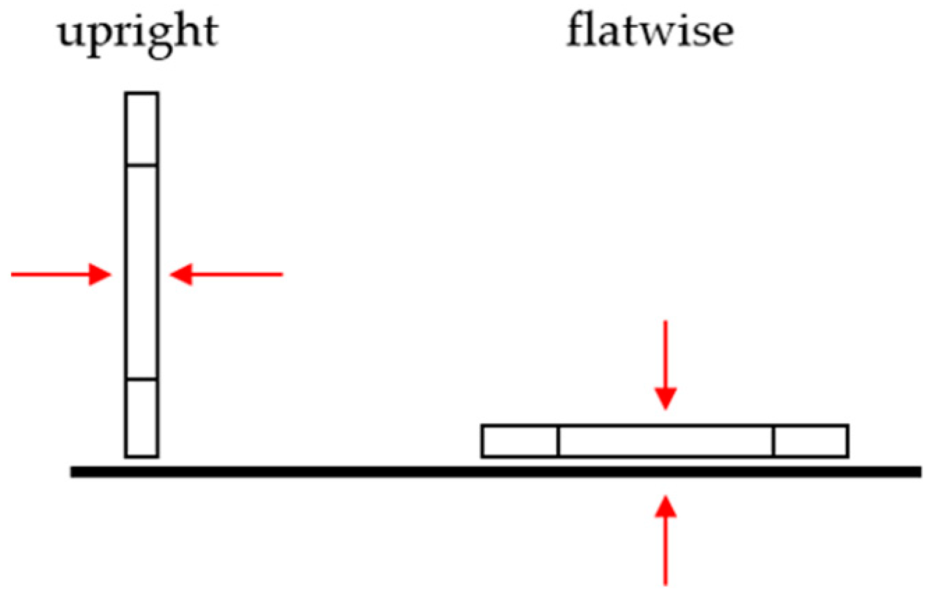
To make a statement about the surface roughness of the sintered parts, the mean roughness value Ra and the mean roughness depth Rz were measured on the front and back of each part in triplicate (see Figure 4). For the tactile measurement of the surface, the MahrSurf PS 10 (Mahr GmbH, Goettingen, Germany) was used.

2.3. Tensile Testing

Tensile testing was performed according to DIN EN ISO 6892-1 procedures A1 and A2 [45]. Five specimens per infill type and orientation were tested on a universal testing machine with a 50 kN Xforce load cell (ZwickRoell GmbH & Co. KG, Ulm, Germany). Strain was measured with a clip-on extensometer 5025-1. A preload of 5 MPa was set, and the test speed (0.0067 s−1) was controlled via a constant strain rate (measured with the extensometer). The Young’s modulus was determined through linear regression between 20 and 40 MPa.

3. Results and Discussion

3.1. Dimensional Deviations

In Figure 5, the weight of the sintered parts is compared to the final weight predicted by the Markforged 3D printing software, Eiger. Eiger’s predicted final metal part mass deviates from the measured one by an average of 3.09%, with Eiger always yielding the lighter value. Thus, the mass prediction in the preprocessor is quite reliable for the different infill structures and print orientations.
Further, the post-sintered dimensions showed that neither the infill type nor the printing orientation influenced the sinter-induced dimensional change significantly. This was to be expected due to all parts in this study being printed with a shell of four wall layers, four bottom layers, and four top layers, all of them solid. The remaining infill was printed using triangular and gyroid patterns. Thus, the sintering shrinkage was not affected by the infill structure either. This is also reflected in the deviations between the sintered specimens and the initial CAD model in Figure 6.
The deviations vary between 1.04% (width) and 3.41% (height). The overall average deviation amounts to 2.23%. This non-uniform sinter shrinkage is one of the key concerns that complicates the design process of ADAM or MEAM parts in general [31,36] and must be considered by tolerance compensation when using ADAM parts in product development. The average shrinkage in the z-direction (H) was the largest, with 15.50% for the flatwise-printed parts and 14.77% for the upright ones, due to the force of gravity during sintering. The smallest shrinkage was observed in the x-direction (L) at 14.25%, thus differing by 1.25%. When compared to other MEAM results, those of Kurose et al. [31] show an average linear shrinkage between 13% and 17%, varying by 4%, while Abe et al. [39] report a linear shrinkage between 15% and 17%. Thus, we conclude that for no configuration, air/gas entrapments or similar occurred during debinding or sintering, which would have been a major concern for geometrical deviations. Further, the results show that the sinter shrinkage can be controlled within about 4% deviation, regardless of the part’s orientation or infill structure used.

3.2. Surface Roughness

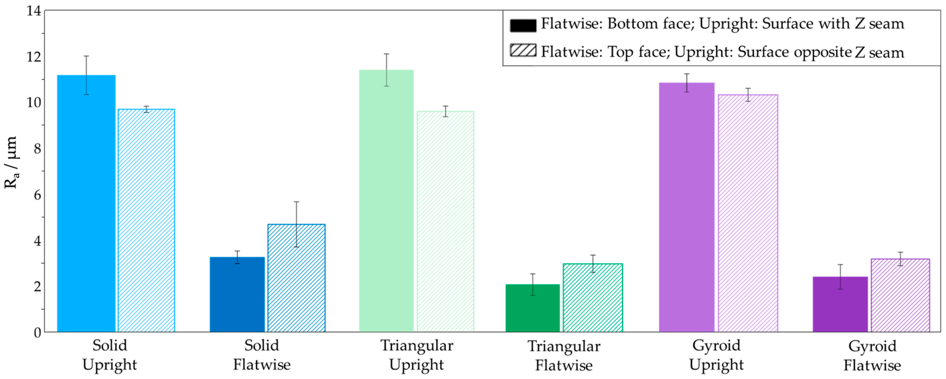
The results of the surface roughness analysis are shown in Figure 7 and Figure 8. In the context of this study, we refer to the general surface, using the primary profile without any filter. Irrespective of the infill type, the upright-printed parts show a higher roughness compared to the flatwise-printed parts at the surface (the Z seam). This seam shows the over-extrusion at layer transitions, leading to printing artifacts and, therefore, a higher surface roughness. For the flatwise-printed parts, the top face shows the highest roughness. This finding is consistent with the results in [46] and is due to remaining filament from previous paths and unbalanced pressure within the printing system [47]. Therefore, a slight over-extrusion at the top face can be the reason for the higher surface roughness. Also, the bottom layer roughness is restricted to the surface structure of the printing bed. The overall trend of flatwise-printed parts having a lower surface roughness is also visible. This can be explained by the fact that when the layers are stacked during printing, they do not fuse together perfectly, as the filament of the lower layer has already cooled down by the time the layer above is printed. The result of this effect is the characteristic unevenness that is considered the “typical FDM surface”. Further, these results confirm the values of Ra measured by Kiswanto et al. [22], which proves the good reproducibility of the ADAM-fabricated Inconel 625 parts.

3.3. Tensile Testing

The results of the tensile testing in Figure 9 show that flatwise-printed specimens with solid infill exhibit the greatest normal force and ultimate tensile strength (UTS) (770 ± 2 MPa), followed by the upright-printed ones with solid infill (UTS: 572.8 ± 10.7 MPa). The specimens with triangular and gyroid infill performed inferiorly, with ultimate tensile strengths of 308 ± 2 MPa (flatwise) and 203 ± 21 MPa (upright) and 284 ± 4 MPa (flatwise) and 194 ± 5 MPa (upright), respectively. While five specimens per configuration were tested, with the exception of the triangular flatwise infill, we observed at least one outlier, which we define as a failure outside of the valid testing range defined by the testing standard [45]. We have noted the number of outliers (out) in the summarized results shown in Table 3, as well as in the caption of Figure 9. For the evaluation, all five specimens were used since the deviations between the measurements—including the outliers—were small. We would rather assume that we can use the number of outliers as an indicator of the configuration’s reliability.
Accordingly, the results indicate that the flatwise-printed specimens with triangular infill are most robust from a process point of view. Regarding the solid specimens, other studies, for instance [3], also report that solid-filled parts in MEAM tend to be over-extruded, leading to slightly higher porosities, in particular between the contour and the inner layer path. These stochastic artifacts can lead to an undesired failure. We further attribute porosities between the contour and the infill structure as the predominant cause for the outliers in other configurations as well.
By analyzing the fracture surfaces of the flatwise-printed specimens, we observed that the gyroid infill structure collapsed in all five specimens either during debinding or sintering. As we show in Figure 10, the collapsed infill accumulated at the bottom of the specimen, resulting in a “half-filled” configuration.
Accordingly, this states that gyroid flatwise specimens cannot be manufactured robustly with ADAM in the current state.
Nevertheless, a concern also known from polymer EAM and early MEAM studies is that only the contour is load-bearing, and the sparse infill does not contribute to the strength of the specimens. While the solid configuration fractured in a straight line, for both infill configurations, different fracture surfaces were visible. The results clearly show that for the flatwise-printed specimens, the crack propagated through the whole structure, whereas for the collapsed gyroid, the crack runs straight through the shell before being deflected at approximately 45° by the accumulated material, as illustrated in Figure 11a. As for the triangular infill, equilateral triangles are used with an inner angle of 60°. We can observe from the specimens that the crack path follows the shape of the infill, which results in an effective breaking angle of 30°, as we illustrated in Figure 11b.
The upright-printed specimens all fractured between two layers, resulting in horizontal fracture lines. This result is similar to the results found by Jasmin et al. [48], which concluded that there are no significant differences in the fracture mechanisms for upright-printed solid and filled polymer specimens. However, it can be clearly indicated that the intact gyroids enable greater movement than the stiff triangles, which results in a nearly doubled fracture elongation at approximately identical effective density. This is further proof that the infill structure is load-bearing and has a significant influence on the effective mechanical performance of the part.
It is nevertheless interesting to observe that the collapsed gyroid structure in the flatwise-printed specimens is equivalent to the intact triangular ones regarding UTS and yield strength, while showing a significantly higher strain at break. Only the Young’s modulus is significantly higher for the flatwise-printed triangular specimens, indicating that the infill pattern predominantly influences the Young’s modulus.
The result of flatwise-printed specimens exhibiting the greatest tensile stress at maximum load is consistent across all infill patterns, due to the tensile strength becoming optimal when the parts are oriented along the direction of loading stress. Hence, these results could be transferred from what was already known for polymer parts (see, for instance, [49]). Generally, intralayer fractures mainly depend on the strength of the extruded material itself, while interlayer strength depends on the strength of the bonds between layers. During tensile testing, the bond between two stacked layers is weak due to the unideal fusion of the layers. Therefore, interlayer fractures occur more easily than intralayer fractures, and, thus, flatwise-printed specimens exhibit greater tensile stresses [50]. Accordingly, we observed intralayer fractures for flatwise-printed specimens and interlayer fractures for upright-printed ones.
Analogously to the UTS results, flatwise-printed specimens also exhibit the greatest ultimate elongation, up to 46.3 ± 0.2% for specimens with solid infill. This even exceeds the ultimate elongation stated in the datasheet (42%). The percentage elongation shows how upright-printed specimens behave more brittlely in comparison to flatwise-printed ones. These results are comparable with the findings by Corapi et al. [51].
Overall, specimens with solid infill exhibit greater tensile strength than those with triangular and gyroid infills due to their higher density. Comparing triangular- and gyroid-filled specimens, the triangular infill performs slightly better, not including flatwise-printed gyroid parts with collapsed infill. This agrees with the results of studies with FDM-printed polymers as reported, for instance, by Parab et al., who showed that the triangular pattern’s mechanical properties exceed those of the gyroid pattern in PLA parts [25]. When comparing build orientations, flatwise-printed specimens show more ductile behavior, with elongations up to 46.3 ± 0.2% and a lower Young’s modulus than upright-printed ones. The layers of upright-printed specimens are built vertically on top of each other. Therefore, they are only interlocked by the adhesion among those layers, not by the printed inner lines. Hence, those parts are fractured more quickly when exposed to the applied force than flatwise-printed ones [52].
Flatwise-printed samples obtain the highest measured tensile strength, with a difference of approx. 27% against upright-oriented specimens. Similar results were achieved by Zaldivar et al. They tested the influence of the build orientation on the mechanical behavior of ULTEM 9085 and found the tensile strength of flatwise-printed specimens to be 21% higher than that of upright-printed parts [53].
It should be noted that the triangular specimens have a relative density of 58% (flatwise) and 60% (upright), while the gyroid specimens have a relative density of 58% (flatwise) and 54% (upright). Thus, in the context of lightweight engineering, it is interesting to observe how the mass-related properties correlate with the relative density. To analyze the results in this context, Table 4 shows the mass-related data of the tensile testing, while the deviation from the flatwise solid reference is given in brackets.
The data elucidate the reinforcing effect of the infill structure. While the mass decreases by about 40%, the mass-related Young’s modulus and yield strength only decrease between 13 and 26%. Nevertheless, this effect is significantly smaller, with relative values about 10% higher than the relative density for gyroid flatwise and 5% for triangular flatwise. Due to the already-explained disadvantages of upright-printed specimens in the plastic regime, the upright-printed specimens show relative values about 10% smaller than the relative density. This correlates to the strain at break, where the upright-printed samples could not achieve 20% of the mass-related reference. Regarding the collapsed infill for the flatwise-printed gyroids, these specimens show a remarkable strain at break. This can be associated with thicker areas inside the specimens due to the collapse, which can mitigate crack growth better than the small facets of the intact triangular infill.
Thus, when comparing the weight savings with the percentual decrease in the mass-related properties in Table 5, it becomes clear that within the elastic regime, the infill structures show clear advantages in the context of lightweight engineering since about 40% of weight can be saved by only losing 20% of mechanical performance. Based on this, the triangular infill pattern proved superior in terms of stiffness and strength, while gyroids led to more ductile specimens.

4. Conclusions

This study aimed to investigate the influence of the printing orientation and type of infill pattern on the mechanical properties and shape deviations of specimens manufactured with Inconel 625 using the ADAM process. The shrinkage of the parts was not influenced by print orientation or the infill pattern. Further, the final weight predicted by the slicing software only showed minor deviations. The surface roughness was strongly influenced by the build orientation and printing bed surface structure but showed no dependence on the infill structure.
As expected, the results showed parts with solid infill exhibiting the greatest UTS (up to 770 ± 2 MPa). Triangular and gyroid infills performed inferiorly, mainly due to their lower infill degree of 59% on average. Regarding build orientation, flatwise-printed specimens were more ductile, showing higher elongations and lower Young’s moduli. The dimensions (length, width, and height) of the specimens, however, were not significantly influenced by the infill pattern or the printing orientation, due to all parts being printed with a shell of four outlines, four bottom layers, and four top layers. The shrinkage because of the sintering process was observed to be largest in the z-direction (15.50%) on account of the force of gravity during sintering. Based on the evaluation of the fracture surface, it is important to note that the gyroid pattern could not withstand the washing and/or sintering process when printed in a flatwise orientation. The infill pattern collapsed, with all the infill accumulating at the bottom of the sample. Therefore, the degree of infill using a gyroid pattern needs to be increased for successful printing results. The evaluation in the context of lightweight engineering shows that infill structures are beneficial within the elastic regime, where 40% weight savings resulted in only a 20% decrease in the specimens’ mechanical performance. The infill patterns also showed slight advantages for ultimate tensile strength while having a harmful influence on strain at break.

Author Contributions

Conceptualization, T.R. and C.S.; methodology, C.S. and T.R.; software, C.S.; validation, T.R., A.S. and C.O.; formal analysis, T.R., C.O. and A.S.; investigation, C.S.; resources, S.T. and B.A.-L.; data curation, T.R.; writing—original draft preparation, C.S., T.R., A.S. and C.O.; writing—review and editing, S.T. and B.A.-L.; visualization, C.S.; supervision, S.T. and B.A.-L.; project administration, B.A.-L. and S.T. All authors have read and agreed to the published version of the manuscript.

Funding

This research received no external funding.

Data Availability Statement

The original contributions presented in the study are included in the article, further inquiries can be directed to the corresponding author.

Acknowledgments

The authors gratefully acknowledge the assistance of Zwick Roell GmbH & Co. KG in performing the experiments.

Conflicts of Interest

The authors declare no conflicts of interest.

References

  1. Gonzalez-Gutierrez, J.; Godec, D.; Kukla, C.; Schlauf, T.; Burkhardt, C.; Holzer, C. SHAPING, DEBINDING AND SINTERING OF STEEL COMPONENTS VIA FUSED FILAMENT FABRICATION. In Proceedings of the 16th International Scientific Conference on Production Engineering—Computer Integrated Manufacturing and High Speed Machining, Zadar, Croatia, 8–10 June 2017; Volume 7. [Google Scholar]
  2. Ramazani, H.; Kami, A. Metal FDM, a New Extrusion-Based Additive Manufacturing Technology for Manufacturing of Metallic Parts: A Review. Prog. Addit. Manuf. 2022, 7, 609–626. [Google Scholar] [CrossRef]
  3. Rosnitschek, T.; Seefeldt, A.; Alber-Laukant, B.; Neumeyer, T.; Altstädt, V.; Tremmel, S. Correlations of Geometry and Infill Degree of Extrusion Additively Manufactured 316L Stainless Steel Components. Materials 2021, 14, 5173. [Google Scholar] [CrossRef] [PubMed]
  4. Sadaf, M.; Bragaglia, M.; Nanni, F. A Simple Route for Additive Manufacturing of 316L Stainless Steel via Fused Filament Fabrication. J. Manuf. Process. 2021, 67, 141–150. [Google Scholar] [CrossRef]
  5. Sadaf, M.; Bragaglia, M.; Slemenik Perše, L.; Nanni, F. Advancements in Metal Additive Manufacturing: A Comprehensive Review of Material Extrusion with Highly Filled Polymers. J. Manuf. Mater. Process. 2024, 8, 14. [Google Scholar] [CrossRef]
  6. Bouaziz, M.A.; Djouda, J.M.; Kauffmann, J.; Hild, F. Microscale Mechanical Characterization of 17-4PH Stainless Steel Fabricated by Atomic Diffusion Additive Manufacturing (ADAM). Procedia Struct. Integr. 2020, 28, 1039–1046. [Google Scholar] [CrossRef]
  7. Coatney, M.D.; Lawrence, B.D.; Henry, T.C.; Nataraj, L.; Hubbard, C. Fatigue Testing of Additively Manufactured 17-4PH Stainless Steel Samples with a Stress Concentration. In Fracture, Fatigue, Failure and Damage Evolution, Volume 3; Beese, A., Berke, R.B., Pataky, G., Hutchens, S., Eds.; Conference Proceedings of the Society for Experimental Mechanics Series; Springer International Publishing: Cham, Switzerland, 2023; pp. 53–60. ISBN 978-3-031-17466-7. [Google Scholar]
  8. Galati, M.; Minetola, P. Analysis of Density, Roughness, and Accuracy of the Atomic Diffusion Additive Manufacturing (ADAM) Process for Metal Parts. Materials 2019, 12, 4122. [Google Scholar] [CrossRef] [PubMed]
  9. Ghadimi, H.; Jirandehi, A.P.; Nemati, S.; Ding, H.; Garbie, A.; Raush, J.; Zeng, C.; Guo, S. Effects of Printing Layer Orientation on the High-Frequency Bending-Fatigue Life and Tensile Strength of Additively Manufactured 17-4 PH Stainless Steel. Materials 2023, 16, 469. [Google Scholar] [CrossRef] [PubMed]
  10. Gong, C.; Djouda, J.M.; Hmima, A.; Gaslain, F.; Chemkhi, M.; Maurer, T.; Panicaud, B. 2D Characterization at Submicron Scale of Crack Propagation of 17-4PH Parts Produced by Atomic Diffusion Additive Manufacturing (ADAM) Process. Procedia Struct. Integr. 2021, 34, 13–19. [Google Scholar] [CrossRef]
  11. Henry, T.C.; Morales, M.A.; Cole, D.P.; Shumeyko, C.M.; Riddick, J.C. Mechanical Behavior of 17-4 PH Stainless Steel Processed by Atomic Diffusion Additive Manufacturing. Int. J. Adv. Manuf. Technol. 2021, 114, 2103–2114. [Google Scholar] [CrossRef]
  12. Lavecchia, F.; Pellegrini, A.; Galantucci, L.M. Comparative Study on the Properties of 17-4 PH Stainless Steel Parts Made by Metal Fused Filament Fabrication Process and Atomic Diffusion Additive Manufacturing. Rapid Prototyp. J. 2023, 29, 393–407. [Google Scholar] [CrossRef]
  13. Lawrence, B.D.; Henry, T.C.; Phillips, F.; Riddick, J.; Kudzal, A. High-Cycle Tension-Tension Fatigue Performance of Additively Manufactured 17–4 PH Stainless Steel. Int. J. Adv. Manuf. Technol. 2023, 126, 777–786. [Google Scholar] [CrossRef]
  14. Opoz, T.T.; Burgess, A.; Ahuir-Torres, J.I.; Kotadia, H.R.; Tammas-Williams, S. The Effect of Surface Finish and Post-Processing on Mechanical Properties of 17-4 PH Stainless Steel Produced by the Atomic Diffusion Additive Manufacturing Process (ADAM). Int. J. Adv. Manuf. Technol. 2024, 130, 4053–4066. [Google Scholar] [CrossRef]
  15. Pellegrini, A.; Lavecchia, F.; Guerra, M.G.; Galantucci, L.M. Influence of Aging Treatments on 17–4 PH Stainless Steel Parts Realized Using Material Extrusion Additive Manufacturing Technologies. Int. J. Adv. Manuf. Technol. 2023, 126, 163–178. [Google Scholar] [CrossRef]
  16. Rodriguez, J.; Zuriarrain, A.; Madariaga, A.; Arrazola, P.J.; Dominguez, E.; Fraile, I.; Soler, D. Mechanical Properties and Fatigue Performance of 17-4 PH Stainless Steel Manufactured by Atomic Diffusion Additive Manufacturing Technology. J. Manuf. Mater. Process. 2023, 7, 172. [Google Scholar] [CrossRef]
  17. Timko, P.; Holubjak, J.; Bechný, V.; Novák, M.; Czán, A.; Czánová, T. Surface Analysis and Digitization of Components Manufactured by SLM and ADAM Additive Technologies. Manuf. Technol. 2023, 23, 127–134. [Google Scholar] [CrossRef]
  18. Agustina, D.; Putra, N. Investigation of Micro CT Based Method for Porosity Estimation of Sintered-Wick Heat Pipes. Heliyon 2023, 9, e13936. [Google Scholar] [CrossRef] [PubMed]
  19. Bordón, P.; Paz, R.; Monzón, M.D. Evaluation of the Performance of Atomic Diffusion Additive Manufacturing Electrodes in Electrical Discharge Machining. Materials 2022, 15, 5953. [Google Scholar] [CrossRef] [PubMed]
  20. Monzón, E.; Bordón, P.; Paz, R.; Monzón, M. Dimensional Characterization and Hybrid Manufacturing of Copper Parts Obtained by Atomic Diffusion Additive Manufacturing, and CNC Machining. Materials 2024, 17, 1437. [Google Scholar] [CrossRef]
  21. Wieczorek, L.; Katzwinkel, T.; Blüm, M.; Löwer, M.; Röttger, A. Supersolidus Liquid Phase Sintering and Heat Treatment on Atomic Diffusion Additive Manufacturing Produced Ledeburitic Cold Work Tool Steel. HTM J. Heat Treat. Mater. 2022, 77, 269–283. [Google Scholar] [CrossRef]
  22. Kiswanto, G.; Kholil, A.; Istiyanto, J. Effect of Infill Pattern on Impact Toughness, Microstructure, and Surface Roughness of Inconel 625 Built via Filament-Based Material Extrusion Additive Manufacturing. J. Manuf. Mater. Process. 2023, 7, 114. [Google Scholar] [CrossRef]
  23. Khan, S.F.; Zakaria, H.; Chong, Y.L.; Saad, M.A.M.; Basaruddin, K. Effect of Infill on Tensile and Flexural Strength of 3D Printed PLA Parts. IOP Conf. Ser. Mater. Sci. Eng. 2018, 429, 012101. [Google Scholar] [CrossRef]
  24. Lalegani Dezaki, M.; Ariffin, M.K.A.M.; Serjouei, A.; Zolfagharian, A.; Hatami, S.; Bodaghi, M. Influence of Infill Patterns Generated by CAD and FDM 3D Printer on Surface Roughness and Tensile Strength Properties. Appl. Sci. 2021, 11, 7272. [Google Scholar] [CrossRef]
  25. Parab, S.; Zaveri, N. Investigating the Influence of Infill Pattern on the Compressive Strength of Fused Deposition Modelled PLA Parts. In Proceedings of International Conference on Intelligent Manufacturing and Automation; Vasudevan, H., Kottur, V.K.N., Raina, A.A., Eds.; Lecture Notes in Mechanical Engineering; Springer: Singapore, 2020; pp. 239–247. ISBN 9789811544842. [Google Scholar]
  26. Sadaf, M.; Cano, S.; Gonzalez-Gutierrez, J.; Bragaglia, M.; Schuschnigg, S.; Kukla, C.; Holzer, C.; Vály, L.; Kitzmantel, M.; Nanni, F. Influence of Binder Composition and Material Extrusion (MEX) Parameters on the 3D Printing of Highly Filled Copper Feedstocks. Polymers 2022, 14, 4962. [Google Scholar] [CrossRef] [PubMed]
  27. Galantucci, L.M.; Pellegrini, A.; Guerra, M.G.; Lavecchia, F. 3D Printing of Parts Using Metal Extrusion: An Overview of Shaping Debinding and Sintering Technology. Adv. Technol. Mater. 2022, 47, 25–32. [Google Scholar] [CrossRef]
  28. Suwanpreecha, C.; Manonukul, A. A Review on Material Extrusion Additive Manufacturing of Metal and How It Compares with Metal Injection Moulding. Metals 2022, 12, 429. [Google Scholar] [CrossRef]
  29. Rosnitschek, T.; Hueter, F.; Alber-Laukant, B. FEM-Based Modelling of Elastic Properties and Anisotropic Sinter Shrinkage of Metal EAM. Int. J. Simul. Model. 2020, 19, 197–208. [Google Scholar] [CrossRef]
  30. Wang, F.; You, S.; Jiang, D.; Ning, F. Study on Sintering Mechanism for Extrusion-Based Additive Manufacturing of Stainless Steel through Molecular Dynamics Simulation. Addit. Manuf. 2022, 58, 102991. [Google Scholar] [CrossRef]
  31. Kurose, T.; Abe, Y.; Santos, M.V.A.; Kanaya, Y.; Ishigami, A.; Tanaka, S.; Ito, H. Influence of the Layer Directions on the Properties of 316L Stainless Steel Parts Fabricated through Fused Deposition of Metals. Materials 2020, 13, 2493. [Google Scholar] [CrossRef] [PubMed]
  32. Damon, J.; Dietrich, S.; Gorantla, S.; Popp, U.; Okolo, B.; Schulze, V. Process Porosity and Mechanical Performance of Fused Filament Fabricated 316L Stainless Steel. Rapid Prototyp. J. 2019, 25, 1319–1327. [Google Scholar] [CrossRef]
  33. Tosto, C.; Tirillò, J.; Sarasini, F.; Cicala, G. Hybrid Metal/Polymer Filaments for Fused Filament Fabrication (FFF) to Print Metal Parts. Appl. Sci. 2021, 11, 1444. [Google Scholar] [CrossRef]
  34. Gonzalez-Gutierrez, J.; Cano, S.; Ecker, J.V.; Kitzmantel, M.; Arbeiter, F.; Kukla, C.; Holzer, C. Bending Properties of Lightweight Copper Specimens with Different Infill Patterns Produced by Material Extrusion Additive Manufacturing, Solvent Debinding and Sintering. Appl. Sci. 2021, 11, 7262. [Google Scholar] [CrossRef]
  35. Gonzalez-Gutierrez, J.; Cano, S.; Schuschnigg, S.; Kukla, C.; Sapkota, J.; Holzer, C. Additive Manufacturing of Metallic and Ceramic Components by the Material Extrusion of Highly-Filled Polymers: A Review and Future Perspectives. Materials 2018, 11, 840. [Google Scholar] [CrossRef]
  36. Thompson, Y.; Gonzalez-Gutierrez, J.; Kukla, C.; Felfer, P. Fused Filament Fabrication, Debinding and Sintering as a Low Cost Additive Manufacturing Method of 316L Stainless Steel. Addit. Manuf. 2019, 30, 100861. [Google Scholar] [CrossRef]
  37. Rane, K.; Strano, M. A Comprehensive Review of Extrusion-Based Additive Manufacturing Processes for Rapid Production of Metallic and Ceramic Parts. Adv. Manuf. 2019, 7, 155–173. [Google Scholar] [CrossRef]
  38. Singh, G.; Missiaen, J.-M.; Bouvard, D.; Chaix, J.-M. Additive Manufacturing of 17–4 PH Steel Using Metal Injection Molding Feedstock: Analysis of 3D Extrusion Printing, Debinding and Sintering. Addit. Manuf. 2021, 47, 102287. [Google Scholar] [CrossRef]
  39. Abe, Y.; Kurose, T.; Santos, M.; Kanaya, Y.; Ishigami, A.; Tanaka, S.; Ito, H. Effect of Layer Directions on Internal Structures and Tensile Properties of 17-4PH Stainless Steel Parts Fabricated by Fused Deposition of Metals. Materials 2021, 14, 243. [Google Scholar] [CrossRef]
  40. Obadimu, S.O.; Kourousis, K.I. Shrinkage Behaviour of Material Extrusion Steel 316L: Influence of Primary 3D Printing Parameters. Rapid Prototyp. J. 2022, 28, 92–101. [Google Scholar] [CrossRef]
  41. Rosnitschek, T.; Glamsch, J.; Lange, C.; Alber-Laukant, B.; Rieg, F. An Automated Open-Source Approach for Debinding Simulation in Metal Extrusion Additive Manufacturing. Designs 2021, 5, 2. [Google Scholar] [CrossRef]
  42. Zhang, Z.; Fidan, I. Machine Learning-Based Void Percentage Analysis of Components Fabricated with the Low-Cost Metal Material Extrusion Process. Materials 2022, 15, 4292. [Google Scholar] [CrossRef]
  43. Zhang, Z.; Femi-Oyetoro, J.; Fidan, I.; Ismail, M.; Allen, M. Prediction of Dimensional Changes of Low-Cost Metal Material Extrusion Fabricated Parts Using Machine Learning Techniques. Metals 2021, 11, 690. [Google Scholar] [CrossRef]
  44. Inconel 625 Filament Datasheet. Markforged Inc: Watertown, MA, USA, 11 May 2019; Available online: https://s3.amazonaws.com/mf.product.doc.images/Datasheets/Translations/DE/Markforged_Inconel_V1_0_de.pdf (accessed on 10 May 2024).
  45. EN ISO 6892-1:2019; Metallische Werkstoffe—Zugversuch—Teil 1: Prüfverfahren Bei Raumtemperatur (Deutsche Fassung). Beuth Verlag GmbH, Deutsches Institut für Normung (DIN): Berlin, Germany, 2020.
  46. Alsoufi, M.S.; Elsayed, A.E. Surface Roughness Quality and Dimensional Accuracy—A Comprehensive Analysis of 100% Infill Printed Parts Fabricated by a Personal/Desktop Cost-Effective FDM 3D Printer. Mater. Sci. Appl. 2018, 09, 11–40. [Google Scholar] [CrossRef]
  47. Alsoufi, M.; Elsayed, A. Quantitative Analysis of 0% Infill Density Surface Profile of Printed Part Fabricated by Personal FDM 3D Printer. Int. J. Eng. Technol. 2018, 7, 44. [Google Scholar] [CrossRef]
  48. Jasim, M.; Abbas, T.; Huayier, A. The Effect of Infill Pattern on Tensile Strength of PLA Material in Fused Deposition Modeling (FDM) Process. Eng. Technol. J. 2022, 40, 1723–1730. [Google Scholar] [CrossRef]
  49. Eryildiz, M. Effect of Build Orientation on Mechanical Behaviour and Build Time of FDM 3D-Printed PLA Parts: An Experimental Investigation. Eur. Mech. Sci. 2021, 5, 116–120. [Google Scholar] [CrossRef]
  50. Wang, S.; Ma, Y.; Deng, Z.; Zhang, S.; Cai, J. Effects of Fused Deposition Modeling Process Parameters on Tensile, Dynamic Mechanical Properties of 3D Printed Polylactic Acid Materials. Polym. Test. 2020, 86, 106483. [Google Scholar] [CrossRef]
  51. Corapi, D.; Morettini, G.; Pascoletti, G.; Zitelli, C. Characterization of a Polylactic Acid (PLA) Produced by Fused Deposition Modeling (FDM) Technology. Procedia Struct. Integr. 2019, 24, 289–295. [Google Scholar] [CrossRef]
  52. Hanon, M.M.; Alshammas, Y.; Zsidai, L. Effect of Print Orientation and Bronze Existence on Tribological and Mechanical Properties of 3D-Printed Bronze/PLA Composite. Int. J. Adv. Manuf. Technol. 2020, 108, 553–570. [Google Scholar] [CrossRef]
  53. Zaldivar, R.J.; Witkin, D.B.; McLouth, T.; Patel, D.N.; Schmitt, K.; Nokes, J.P. Influence of Processing and Orientation Print Effects on the Mechanical and Thermal Behavior of 3D-Printed ULTEM® 9085 Material. Addit. Manuf. 2017, 13, 71–80. [Google Scholar] [CrossRef]
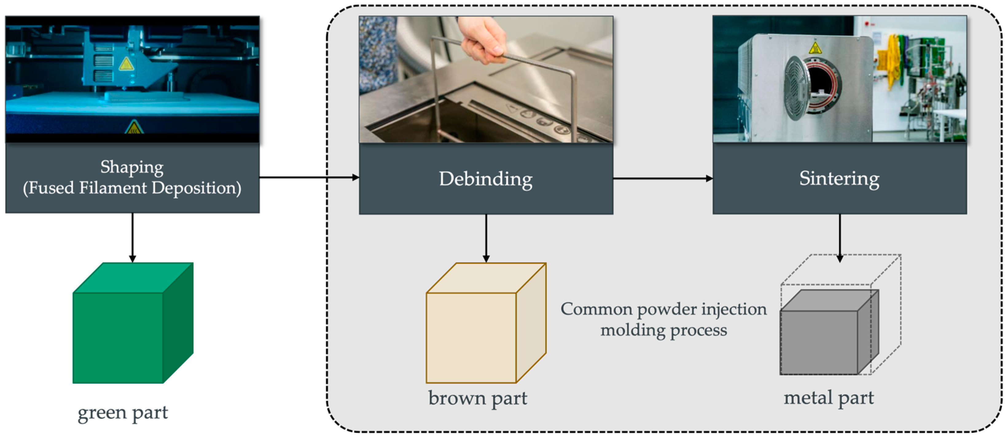
Figure 1. Schematic overview of the MEAM process, adapted from [3].
Applmech 05 00022 g001
Figure 2. Sketch of the cross-sections of the used specimens made in Eiger.
Applmech 05 00022 g002
Figure 3. Tensile specimen with a total length of 114 mm. Specimens were printed upright and flatwise.
Applmech 05 00022 g003
Figure 4. Schematic diagram of the surfaces where the roughness was measured.
Applmech 05 00022 g004
Figure 5. Comparison of the measured weight of metal specimens with different infills and printing orientations and the weight predicted by the printing software Eiger.
Applmech 05 00022 g005
Figure 6. Dimensional deviations between the sintered specimens and the CAD model.
Applmech 05 00022 g006
Figure 7. Surface roughness mean value analysis of sintered specimens with different printing orientations and infill patterns.
Applmech 05 00022 g007
Figure 8. Surface roughness mean depth analysis of the sintered specimens with different printing orientations and infill patterns.
Applmech 05 00022 g008
Figure 9. Overview of the tensile test results, n = 5. All curves represent the average for each condition (solid: out = 1; gyroid: out = 3; triangular flatwise: out = 0; triangular upright: out = 2).
Applmech 05 00022 g009
Figure 10. Collapsed infill structure of all 5 gyroid flatwise specimens (left) compared to the successful sintered infill structure of the gyroid upright specimens (right).
Applmech 05 00022 g010
Figure 11. Illustration of the fractures for (a) collapsed gyroid flatwise and (b) triangular flatwise, where the crack path (yellow) follows the contour of the equilateral triangle infill structure.
Applmech 05 00022 g011
Table 1. The metal additive manufacturing market in 2020, according to [2].
Metal Additive ManufacturingMarket Share in 2020
Powder bed fusion54%
Material Extrusion10%
VAT photopolymerisation2%
Lamination2%
Material/binder jetting16%
Direct energy deposition16%
Table 2. Process parameters for all configurations in Eiger.
Solid
Flatwise
Solid
Upright
Gyroid
Flatwise
Gyroid
Upright
Triangular
Flatwise
Triangular
Upright
As printed (mm)137.2 × 18.1 × 3.6135.8 × 18.1 × 3.6137.2 × 18.1 × 3.6135.8 × 18.1 × 3.6137.2 × 18.1 × 3.6135.8 × 18.1 × 3.6
As sintered (mm)114.0 × 15.0 × 3.0114.0 × 15.0 × 3.0114.0 × 15.0 × 3.0114.0 × 15.0 × 3.0114.0 × 15.0 × 3.0114.0 × 15.0 × 3.0
Layer height (mm)0.1250.1250.1250.1250.1250.125
Roof and floor layers--4444
Wall layers224444
Nozzle temperature220 °C220 °C220 °C220 °C220 °C220 °C
Bed temperature112 °C112 °C112 °C112 °C112 °C112 °C
Chamber temperature48°48°48°48°48°48°
Print time2 h 37 min5 h 30 min2 h 22 min5 h 24 min2 h 5 min5 h 5 min
Wash time12 h12 h4 h4 h4 h4 h
Dry time4 h4 h4 h4 h1 h1 h
Printed part mass (g)42.4750.2824.6129.7424.8232.74
Final part mass (g)37.8338.5721.9120.2722.122.94
Metal volume (cm3)7.749.154.485.414.525.96
Table 3. Tensile testing data compared to the Inconel 625 datasheet [44]. Out represents the number of outliers per configuration.
ConfigurationOutYoung’s Modulus in GPaYield Strength in MPaUltimate Tensile Strength in MPaStrain at Break in %
Solid flatwise1194.75 ± 7.01327.5 ± 1.80769.75 ± 1.4846.31 ± 0.82
Solid upright1202.25 ± 26.6308.25 ± 1.64572.75 ± 10.6914.06 ± 1.32
Gyroid flatwise387.50 ± 2.50145.5 ± 0.5308.00 ± 2.0020.62 ± 0.50
Gyroid upright377.00 ± 4.00138.00 ± 1.00194.00 ± 5.004.33 ± 0.70
Triangular flatwise098.6 ± 6.92155.4 ± 1.96284.2 ± 4.1715.11 ± 0.52
Triangular upright2101.33 ± 6.65166.67 ± 0.94203.00 ± 21.122.83 ± 0.90
Datasheet [44]n.a.n.a.33476542
Table 4. Mass-related (MR) tensile testing data. Out represents the number of outliers per configuration. The relative values compared to the reference are given in brackets.
ConfigurationOutMR Young’s Modulus in GPa/kgMR Yield Strength in MPa/kgMR Ultimate Tensile Strength in MPa/kgMR Strain at Break in %/kg
Solid flatwise45148 (100%)8657 (100%)20,348 (100%)1224 (100%)
Solid upright45244 (102%)7992 (92%)14,850 (73%)365 (30%)
Gyroid flatwise23994 (77%)6640 (77%)14,058 (69%)941 (77%)
Gyroid upright23799 (74%)6808 (79%)9571 (47%)214 (18%)
Triangular flatwise54462 (87%)7032 (81%)12,860 (63%)684 (56%)
Triangular upright34417 (86%)7266 (84%)8849 (44%)123 (10%)
Table 5. Comparison of percentual weight savings and percentual decrease in mass-related tensile testing data. MR = mass-related; YM = Young’s modulus; YS = yield strength; UTS = ultimate tensile strength.
ConfigurationSaved WeightMR-YMMR-YSMR-UTSMR Strain
Gyroid flatwise42%22%23%31%23%
Gyroid upright46%26%21%53%82.5%
Triangular flatwise42%13%19%37%44%
Triangular upright40%14%16%56%90%
Disclaimer/Publisher’s Note: The statements, opinions and data contained in all publications are solely those of the individual author(s) and contributor(s) and not of MDPI and/or the editor(s). MDPI and/or the editor(s) disclaim responsibility for any injury to people or property resulting from any ideas, methods, instructions or products referred to in the content.