Article

On the Countering of Free Vibrations by Forcing: Part II—Damped Oscillations and Decaying Forcing

by
Luiz M. B. C. Campos
and
Manuel J. S. Silva
*,†
CCTAE, IDMEC, LAETA, Instituto Superior Técnico, Universidade de Lisboa, Av. Rovisco Pais 1, 1049-001 Lisboa, Portugal
*
Author to whom correspondence should be addressed.
These authors contributed equally to this work.
Appl. Mech. 2023, 4(1), 141-178; https://doi.org/10.3390/applmech4010009
Submission received: 30 September 2022 / Revised: 22 December 2022 / Accepted: 22 January 2023 / Published: 31 January 2023
(This article belongs to the Special Issue Feature Papers in Applied Mechanics)

Abstract

:
The present two-part paper concerns the active vibration suppression for the simplest damped continuous system, namely the transverse oscillations of an elastic string, with constant tension and mass density per unit length and friction force proportional to the velocity, described by the telegraph or wave-diffusion equation, in two complementary parts. The initial part I considers non-resonant and resonant forcing, by concentrated point forces or continuous force distributions independent of time, with phase shift between the forced and free oscillations, in the absence of damping, in which case the forced telegraph equation reduces to the forced classical wave equation. The present and final part II uses the forced wave-diffusion equation to model the effect of damping, both as amplitude decay and phase shift in time, for non-resonant and resonant forcing by a single point force, with constant magnitude or magnitude decaying exponentially in time at an arbitrary rate. Assuming a finite elastic string fixed at both ends, the free oscillations are (i) sinusoidal modes in space-time with exponential decay in time due to damping. The non-resonant forced oscillations at an applied frequency distinct from a natural frequency are also (ii) sinusoidal in space-time, with constant amplitude and a phase shift such that the work of the applied force balances the dissipation. For resonant forcing at an applied frequency equal to a natural frequency, the sinusoidal oscillations in space-time have (iii) a constant amplitude and a phase shift of π / 2 . In both cases, the (ii) non-resonant or (iii) resonant forcing dominates the decaying free oscillations after some time. Even by optimizing the forcing to minimize the total energy of oscillation, it remains below the energy of the free oscillation alone, but only for a short time—generally a fraction of the period. A more effective method of countering the damped free oscillations is to use forcing with amplitude decaying exponentially in time; by suitable choice of the forcing decay relative to the free damping, the total energy of oscillation over all time can be reduced to no more than 1 / 16 th of the energy of the free oscillation.

1. Introduction

The active suppression of oscillations is considered: (i) in acoustics [1,2,3,4,5,6,7] by considering anti-noise sources that generate sound with opposite phase [8,9]; (ii) in solid mechanics [10,11,12,13,14,15,16,17,18,19,20] using forces and moments to oppose the vibrations [21,22,23,24,25,26,27,28,29,30,31]. In an earlier study [32], which has an extensive bibliography, the authors considered an hybrid approach using forced oscillations superimposed on the free oscillations of an elastic sting, in the simplest case of constant tangential tension and with constant mass density per unit length, in the absence of damping. The countering of free vibrations by forcing without damping was considered in part I [32] for non-resonant forcing by point and distributed forces, allowing for different phases of the free oscillation and of the forcing. After considering all possible cases without damping, it was found that suppression of oscillations or a reduction of their energy was of limited effectiveness and for short periods.
These not-so-promising results motivate the extension in the present part II to include damping, which causes amplitude decay and introduces a third phase. The physical mechanisms of damping, decay, or dissipation include friction or viscosity in fluids [19,33,34,35,36,37,38,39,40,41,42,43,44,45,46] and solids [10,12,14,18,19,20,47,48,49,50,51,52,53,54,55,56,57,58,59], thermal conduction [60,61,62,63,64,65,66,67,68,69,70,71,72,73] or radiation [74,75,76], phase changes [77,78,79,80,81,82,83,84], and electrical effects such as resistance [36,85,86,87,88,89,90,91,92]. In the simplest case of a mechanical circuit with masses, springs, dampers, and applied forces [91,93,94,95,96,97,98,99,100,101,102,103,104,105,106,107,108,109] or the equivalent electrical circuit consisting of resistors, capacitors, and batteries [110,111,112,113,114,115], the forcing of oscillations is most often considered with amplitude independent of time. The case of forcing with amplitude exponentially decaying in time [116] is shown in the present paper to be far more effective at vibration suppression than forcing with constant amplitude.
In part II, again non-resonant and resonant forcing is considered, and the inclusion of damping still does not lead to effective vibration suppression, for constant damping amplitude. The countering of vibrations or partial vibration suppression is quite effective for forcing decaying exponentially with time with a suitably chosen decay rate. Thus the main difference between parts I and II is the inclusion of damping and allowing for forcing decaying exponentially in time. This implies replacing the classical wave equation for the transverse displacement of the elastic string by the wave-diffusion or telegraph equation.
The background literature addresses two distinct problems: (i) the transverse vibrations of an elastic string, corresponding to one-dimensional acoustics (references 1–48 in Ref. [32]), for which active sound cancellation corresponds to superposition of a wave with the same amplitude and opposite phase; (ii) transverse vibrations of elastic bars for which active vibration suppression is done by applied forces or moments (references 49–120 in Ref. [32]). The present problem is an hybrid since it considers (i) transverse vibrations of an elastic string and (ii) attempts suppression by applied forces. There are four combinations of the superposition of free and forced oscillations: (a) absence or presence of damping; (b) non-resonant or resonant forcing. The cases of superposition of resonant and non-resonant forcing with free oscillations were considered without damping in part I [32], as a baseline to add damping effects in the present part II. The distinction starts with the fundamental equation, namely the classical wave equation in part I [32] is extended to the wave-diffusion or telegraph equation to include damping in the present part II.
The free or unforced solutions are (Section 2) sinusoidal waves in space-time with amplitude decaying exponentially in time due to dissipation; the wavenumbers and frequencies are determined by boundary conditions fixing the string at the two ends (Section 2.1) and the amplitude and phase are specified by the initial displacement and velocity (Section 2.2). The sinusoidal forcing of the damped space-time oscillation with applied frequency and phase leads (Section 3) to two cases: (i) non-resonant case if the applied frequency is distinct from the natural frequency leading (Section 3.1) to forced space-time oscillations with constant amplitude and a phase shift such that the work of the applied force balances the dissipation; (ii) resonant case if the applied frequency equals the natural frequency and (Section 3.2) the space-time oscillations have a constant amplitude with a phase shift of π / 2 . In both cases, the decaying free oscillation is dominated (Section 3.3) for a long time by the forced (i) non-resonant or (ii) resonant oscillation with constant amplitude.
The total energy (Section 4) is the sum of (i) the kinetic energy associated to the transverse velocity and mass density with (ii) the elastic energy associated to the slope and tangential tension. The total energy decays for the damped free oscillation, but not when the forced oscillation is superimposed either in the (i) non-resonant (Section 4.1) or (ii) resonant (Section 4.2) cases, because forcing leads to constant amplitude. Thus, an energy of the total, free plus forced, oscillation less than for the free oscillation is possible only: (i) by selecting the forcing to oppose the free oscillation; (ii) matching the applied phase to the phase of free oscillation and phase shift due to damping; (iii) for a sufficiently short-time.
Total cancellation of the free oscillation by forcing is not possible because: (i) the amplitudes vary differently in time, namely exponential decay for the free oscillation, constant amplitude for the forced non-resonant or resonant oscillation; (ii) the phases are different for the free and forced oscillations, with the frequency being the same for the forced resonant oscillation or with the frequency also being different for the forced non-resonant oscillation. In conclusion, even by optimizing the forcing, the total energy of the free plus forced oscillation can be less than the energy of the free oscillation only for a short time, usually a small fraction of the first period of oscillation.
It follows that the objective of substantial suppression of free oscillations over several periods is not attainable by the four standard strategies I-IV of superimposing: (I) non-resonant undamped, (II) resonant undamped, (III) non-resonant damped, and (IV) resonant damped oscillations.
This is the motivation to consider the two novel strategies, namely (V) resonant and (VI) non-resonant forcing with exponential time decay. The forcing with exponential time decay (Section 5) can be considered with: (i) opposite free and forcing amplitudes; (ii) matched free, applied, and damping phases; (iii) applied frequency equal to oscillation frequency. This leads to resonance (Section 5.2) if the forcing decay equals damping, but no resonance otherwise (Section 5.1).
Considering the energy of the total free plus forced oscillation in the strategy V of forcing decay equal to damping (Section 6), the forced oscillation has an amplitude initially increasing linearly with time, until dominated by exponential time decay at a later time. The build up of energy of the forced oscillation (Section 6.1) may be too slow to compensate for the damping of the free oscillation with little or no benefit of overall energy reduction (Section 6.2).
The final most effective strategy VI is to avoid resonance by having a forcing decay distinct from damping (Section 7) which is compatible with: (i) applied frequency equal to oscillation frequency; (ii) opposite free and forcing amplitudes; (iii) matched free, damping, and applied phases. In this case, both the free and forced oscillations decay exponentially with time (Section 7.1) at different damping and decay rates, both leading to finite energy over all time. Their ratio can be adjusted to achieve a reduction of the energy over all time of the total oscillation of more than 96% relative to the free oscillation (Section 7.2). In conclusion (Section 10), the strategy VI is the most effective at partial suppression of free oscillations (Section 8). It also suggests a redefinition of the concept of resonance for more general types of forcing than constant amplitude (Section 9).

2. Free Damped Modes with Dissipation

The free damped waves are described by the unforced wave diffusion equation with boundary conditions, specifying the wavenumbers and frequencies (Section 2.1), and with the initial conditions, specifying the amplitudes and phases (Section 2.2).

2.1. Wavenumbers and Frequencies from Wave-Diffusion Equation

The classical wave equation applies to the linear transverse vibration y ˜ of an elastic string with constant tangential tension T and mass density per unit length ρ . It is extended in the presence of damping μ proportional to the velocity to:
ρ 2 y ˜ t 2 + μ y ˜ t T 2 y ˜ x 2 = 0 ,
which can be written in the form of a wave-diffusion equation:
2 y ˜ x 2 1 χ y ˜ t 1 c 2 2 y ˜ t 2 = 0 ,
involving, besides the wave speed:
c T ρ ,
also the diffusivity:
χ T μ .
In the absence of damping, μ = 0 , the diffusivity is infinite, χ = , and the wave-diffusion Equation (2) reduces to the classical wave equation:
2 y ˜ t 2 c 2 2 y ˜ x 2 = 0 .
Considering an elastic string of length L held at the two ends, y ˜ 0 , t = 0 = y ˜ L , t , the spatial eigenfunctions are:
y ˜ n x = sin k n x
with wavenumbers:
k n = n π L .
The solution of the wave-diffusion equation is sought by separation of variables in the form:
y ˜ x , t = n = 1 T n t sin k n x ,
leading to:
d 2 T n d t 2 + c 2 χ d T n d t + k n c 2 T n = 0 .
There is a solution exponential in time:
T n t = exp v n t ,
with v n satisfying:
v n 2 + c 2 χ v n + k n c 2 = 0 ,
whose roots are:
v n ± = c 2 2 χ ± c 2 2 χ 2 k n c 2 ,
and thus:
T n t = P n exp v n + t + Q n exp v n t ,
where P n and Q n are constants determined by the initial conditions.

2.2. Amplitudes and Phases from Initial Displacement and Velocity

In the case of high diffusivity or sub-critical damping:
k n > c 2 χ ,
the roots (11) are:
v n ± = δ ± i ω ˜ n ,
where:
δ = c 2 2 χ
plays the role of damping and
ω ˜ n = k n c 2 c 2 2 χ 2 = k n c 2 δ 2
plays the role of oscillation frequency. After substituting (14) in (12), it is rewritten as:
T n t = e t δ P n e i ω ˜ n t + Q n e i ω ˜ n t = e t δ P n + Q n cos ω ˜ n t + i P n Q n sin ω ˜ n t .
Choosing the amplitude A n and phase α n by:
P n + Q n = A n cos α n ,
i P n Q n = A n sin α n ,
with inverses:
A n = P n + Q n 2 + i P n Q n 2 = 2 P n Q n ,
tan α n = i P n Q n P n + Q n ,
leads to the real solution
T n t = e t δ A n cos ω ˜ n t α n .
Substitution of (20) in (7) specifies the free vibrations of the string:
y ˜ x , t = e t δ n = 1 A n sin k n x cos ω ˜ n t α n ,
that consist of a superposition of modes: (i) all with the same damping (15); (ii) with wavenumbers (6) related to the wavelength λ n by:
λ n 2 π k n = 2 L n ;
(iii) with oscillation frequencies (16):
ω ˜ n = c k n 2 c 2 χ 2 ;
(iv) with amplitudes A n and phases α n determined by the initial displacement:
y ˜ x , 0 = n = 1 A n sin k n x cos α n ,
and initial velocity:
y ˜ t x , 0 = n = 1 A n δ cos α n ω n sin α n sin k n x .
The Fourier sine series (24a) and (24b) may be inverted to specify the coefficients:
A n cos α n = 1 L 0 L y ˜ x , 0 sin k n x d x X n ,
A n sin α n δ ω n A n cos α n = 1 ω n L 0 L y ˜ t x , 0 sin k n x d x Y n .
Rewriting (25b) in the form:
A n sin α n = δ ω n X n + Y n ,
it follows that the amplitudes and phases are given by:
A n = X n 2 + Y n + δ ω n X n 2 1 / 2 ,
tan α n = Y n X n + δ ω n .
In the non-dissipative case δ = 0 , the shape of the string is given by
y ˜ x , t = n = 1 A n sin k n x cos ω n t α n ,
with ω n = k n c in agreement with the Equation (6d) in Ref. [32].
Figure 1 shows the dimensionless amplitudes, y ˜ / A , of the free oscillations (for instance, of a string), without forcing, versus dimensionless axial coordinate x / L . All the oscillations shown in the figure result from Equation (21). Each line corresponds to one term of the series in (21), depending on the mode of oscillation n (or depending on the row of the figure). The total deformation of the string is the sum of all the contributions of each natural mode n of oscillation. The deformation is dominated by the natural modes with greater values of A n (in modulus) which depend on the boundary conditions. The blue solid lines correspond to oscillations without damping, δ = 0 , whereas the red dashed lines are for oscillations with damping, δ = 0.5 c / L . Figure 1 shows three distinct situations regarding the values of the mode of oscillation n and consequently the values of wavenumber k n . The upper plots are obtained for n , k n = 1 , π / L , the plots at the middle row are for n , k n = 2 , 2 π / L and the bottom plots correspond to n , k n = 3 , 3 π / L . The oscillation frequencies ω ˜ n are obtained from (16). In all the three cases, the oscillations are shown for three distinct times: t = 0 , 0.5 , 1 L / c . The plots are obtained with no phase shift, α n = 0 . There is no loss of generality in the next figure to set α n = 0 because the phase α n of each mode may be eliminated by changing the time t to t = t α n / ω ˜ n . In all the plots, the vibration is always fixed with y ˜ = 0 at the two ends of the string because that was imposed as the boundary conditions.
By comparing the lines of Figure 1, the effect of changing the mode of oscillation n, which corresponds to one term of the series in (21), can be observed. The mode of oscillation n has direct effects on the values of spatial wavenumber k n and consequently on the temporal frequency ω n . The two effects can be studied separately because the solution of the differential Equation (2) was deduced by separation of the temporal and spatial variables, t and x, respectively. The first effect, specifically the changing of the value of spatial wavenumber k n , can be noticed by comparing the plots of Figure 1 for the same time, for instance, at times t = 0 and t = 1 L / c . The bottom plots are obtained for a higher value of n, therefore for a higher value of wavenumber k n , compared to the top plots. Increasing the wavenumber means reducing the wavelength of the vibration, according to Equation (22). Therefore, the bottom plots show a vibration with a higher number of crests, troughs, and nodes, since the vibration is spatially more “compact”. For each mode n, the string has n peaks and n 1 nodes (not counting the both ends of the string). These peaks and nodes remain at the same positions all the time due to the separation of the variables x and t in the solution. For a higher mode of oscillation n, the temporal frequency ω ˜ n also increases and consequently the movement of the vibration is faster (the period of oscillations is lower), that is, it increases the velocity of the wave for the same velocity of propagation c and decay rate δ ; this property is verified in (16). For instance, in the case of Figure 1, in the upper plots where the frequency is lower (the period is greater), the stage of vibration at t = 1 L / c is the same as at t = 0.5 L / c in the intermediate plots where the frequency is greater (the period is lower). The stage of vibration at t = 1 L / c of the intermediate row is only reached by the vibration of the upper row at t = 2 L / c (these equivalences of stages of vibration neglect the effect of damping). Another difference is related to the direction of the movement of the oscillation. For instance, although the upper and lower plots of Figure 1 are identical at the time t = 0.5 L / c , the direction of the movement is not the same: in the upper plot the string is moving downwards whereas in the lower plot the string is moving upwards. Figure 1 also shows the effect of the value of decay rate δ . At the initial time, there is no difference between the plots with and without damping. When δ = 0 , as in the blue solid lines of the plots, there is no damping and the maximum amplitudes (in modulus) of the vibration remain constant over time. When δ 0 , the vibrations are damped and the amplitudes of the vibrations are decreasing over time (the vibrations cease to exist when t ). The greater the damping value, the faster the oscillations are damped. In addition, the presence of damping changes the temporal frequency ω ˜ n , according to (16). With damping, the temporal frequency decreases and consequently the period of the oscillation is greater.
The damped oscillations are considered both free (Section 2) and with forcing (Section 3).

3. Forced Oscillations with Applied Frequency and Phase

Next, we consider the forcing of the wave diffusion equation (Section 2) with constant amplitude, and an arbitrary frequency and phase shift (Section 3.1). The cases of applied frequency distinct from or equal to the natural frequency lead respectively to non-resonant or resonant forcing (Section 3.2). This allows a comparison of total, free plus forced, oscillations in the non-resonant and resonant cases (Section 3.3).

3.1. Damped Non-Resonant Forced Oscillations with Phase Shift

Next we consider the forced oscillations with damping and forcing of the dissipative wave-diffusion Equation (2) with the same wavenumber k n k as one mode of natural oscillation, applied frequency ω ¯ and phase shift β in:
2 y ¯ x 2 1 χ y ¯ t 1 c 2 2 y ¯ t 2 = F sin k x exp i ω ¯ t i β .
with a phase shift β distinct from the free oscillation (21) when each mode n has a phase shift α n . The solution of (28) is sought as a plane wave with the same wavenumber k n k , applied frequency ω ¯ , and phase shift β :
y ¯ x , t = B sin k x exp i ω ¯ t i β .
Substitution of (29) in (28) and omission of common space-time dependence leads to:
c 2 F B = ω ¯ 2 + i ω ¯ c 2 χ k 2 c 2 .
The substitution of the damping (16) gives:
c 2 F B = ω ¯ 2 k 2 c 2 + 2 i ω ¯ δ E e i ϕ ,
corresponding to: (i) the amplitude factor:
E = ω ¯ 2 k 2 c 2 2 + 4 ω ¯ 2 δ 2 1 / 2 ,
(ii) the phase factor:
tan ϕ = 2 ω ¯ δ ω ¯ 2 k 2 c 2 .
Using the oscillation frequency (16) in (31) leads to the alternative results:
c 2 F B = ω ¯ 2 ω ˜ 2 δ 2 + 2 i ω ¯ δ = E e i ϕ ,
and hence to the amplitude factor:
E = ω ¯ 2 ω ˜ 2 δ 2 2 + 4 ω ¯ 2 δ 2 1 / 2 ,
and phase factor:
tan ϕ = 2 ω ¯ δ ω ¯ 2 ω ˜ 2 δ 2 .
In the non-resonant case of distinct applied and natural frequencies, ω ¯ k c , then the Equation (31) can be solved for B, and substitution in (29) specifies the forced damped oscillation:
y ¯ x , t = c 2 F E sin k x exp i ω ¯ t + β + ϕ .
Taking real parts, the forced wave diffusion Equation (28):
2 y ¯ x 2 1 χ y ¯ t 1 c 2 2 y ¯ t 2 = F sin k x cos ω ¯ t + β ,
leads to the forced oscillations:
y ¯ x , t = c 2 F E sin k x cos ω ¯ t + β + ϕ = c 2 F ω ¯ 2 k 2 c 2 2 + 4 ω ¯ 2 δ 2 1 / 2 sin k x cos ω ¯ t + β + ϕ .
Figure 2 shows the dimensionless amplitudes, y ¯ / F L 2 , of the forced oscillations at three distinct times: t = 0 , 0.5 , 1 L / c . All the oscillations shown in the figure result from Equation (37). The blue solid lines correspond to oscillations without damping, δ = 0 , whereas the red dashed lines are for oscillations with damping, δ = 0.5 c / L . Figure 2 shows three distinct situations regarding the values of the mode of oscillation n (or as a consequence in the wavenumber k = n π / L ) and forced ω ¯ frequency. The upper plots are obtained for n , ω ¯ = 1 , 4 π c / L , the plots at the middle row are for n , ω ¯ = 2 , 4 π c / L and the bottom plots correspond to n , ω ¯ = 1 , 3 π c / L . In all the three cases, ω ¯ k c means that the oscillations are not resonant.
The values of the mode of oscillation and forced frequency influence the amplitude and phase of the oscillation. The presence of damping attenuates the amplitude of oscillations. Indeed, Equation (32a) shows that when the value of damping δ increases, the amplitude factor E is greater and consequently the amplitude of oscillation decreases. The other effect of damping that can be visualized in Figure 2 is that it delays the stage of oscillation. This property can be confirmed by Equation (32b) with the existence of damping δ . As opposed to the free oscillations, the maximum and minimum amplitudes of the forced oscillations remain constant over time. The amplitude of the oscillation does not depend on time.
The free oscillation is considered for the mode n with the simplified notation k n , ω ˜ n , A n , α n substituted by k , ω ˜ , A , α in:
y ˜ x , t = A exp t δ sin k x cos ω ˜ t α ,
and adds to the forced oscillation (37) in the total oscillation:
y x , t = y ˜ x , t + y ¯ x , t = sin k x A e t δ cos ω ˜ t α + c 2 F E cos ω ¯ t + β + ϕ ,
showing that the cancellation for all time is not possible because: (i) the applied ω ¯ and oscillation ω ˜ (16) frequencies are generally distinct:
ω ¯ ω ˜ = k 2 c 2 δ 2 ;
(ii) the free damped oscillations decay exponentially with time,
lim t y ˜ x , t = 0 ;
(iii) the forced oscillations have constant amplitude and dominate for a long-time:
lim t y x , t = y ¯ x , t = c 2 F E sin k x cos ω ¯ t + β + ϕ .
Choosing the forcing amplitude:
F = E A c 2 = A c 2 ω ¯ 2 k 2 c 2 2 + 4 ω ¯ 2 δ 2 1 / 2 ,
still does not cancel the total oscillation at any time:
y x , t = A sin k x e t δ cos ω ˜ t α cos ω ¯ t + β + ϕ ,
because y x , t = 0 would require:
Re exp i ω ˜ t i α t δ = Re exp i ω ¯ t + i β + i ϕ ,
that is equivalent to:
i ω ˜ t i α t δ = i ω ¯ t + i β + i ϕ + i 2 π p ,
where p is an integer; solving (46) leads to a complex time:
t = α + β + ϕ + 2 π p ω ˜ ω + i δ ,
and thus the total oscillation (44) cannot vanish for real time.
Figure 3 shows the dimensionless amplitudes, y / A , of the total (free plus forced) oscillations at three distinct times: t = 0 , 0.5 , 1 L / c , and equating the unknown constants of both oscillations, A = F L 2 . All the oscillations shown in the figure result from Equation (39), by defining the values of ω ¯ , k (or mode of oscillation n) and δ , as in Figure 1 and Figure 2. The phase shifts are equal to zero, α = 0 = β . The blue solid lines correspond to oscillations without damping, δ = 0 , whereas the red dashed lines are for oscillations with damping, δ = 0.5 c / L . Figure 3 shows three distinct situations, one for each line. The three situations, regarding the values of mode of oscillation n and forced frequency ω ¯ , are the same as in Figure 2. In all the three cases, the wavenumber is related to the mode of oscillation by k = n π / L . Consequently, in all the cases, ω ¯ k c means non-resonant oscillations.
In this particular set of values of forced frequency, wavenumber, and damping ratio, the amplitudes of forced oscillations are much smaller than the amplitudes of free oscillations. Therefore, the total oscillation is almost reduced to only free oscillations, unless the value of the force F is much greater than the value of the constant A. Ultimately for a sufficiently long time, the forced oscillation with constant amplitude will always dominate the exponentially decaying free oscillation, as stated in (42).

3.2. Resonant Forced Oscillation with Dissipation and Phase Shift

The resonant case corresponds to applied frequency ω ¯ equal to the natural frequency:
ω ¯ = k c ,
implying that (31) simplifies to
c 2 F B = i 2 ω ¯ δ = i 2 k c δ = E e i ϕ ,
corresponding to the amplitude factor:
E = 2 ω ¯ δ = 2 k c δ ,
and phase shift of 90 degrees:
ϕ = π 2 .
From (49) follows:
B = i c F 2 k δ ,
implying by (29) the resonant forced oscillation:
y ¯ x , t = c F 2 k δ sin k x sin k c t + β .
The non-resonant case, ω ¯ k c , is valid for zero damping, δ = 0 , when the amplitude factor (32a) simplifies to
E = ω ¯ 2 k 2 c 2 ,
and the phase (32b) zero,
ϕ = 0 ,
and leads (37) to the undamped non-resonant forced oscillation:
y ¯ x , t = F ω ¯ 2 / c 2 k 2 sin k x cos ω ¯ t + β .
In the case of resonant forcing (48), the limit of zero damping δ 0 is not valid, because it involves a division by zero in (53); the correct solution [32] involves a linear increase of amplitude with time. Henceforth only the case with damping will be considered when comparing (Section 3.3) non-resonant (Section 3.1) with resonant (Section 3.2) forcing.

3.3. Comparison of Total Free Damped Oscillation plus Resonant or Non-Resonant Forcing

The comparison of non-resonant forcing (37) with ω ¯ k c and resonant forcing (53) with ω ¯ = k c shows that: (i) the amplitude is constant both for non-resonant forcing (37) and for resonant forcing (53); (ii) the resonant amplitude factor (50) coincides with the second term in the non-resonant factor (32a), excluding the first term, ω ¯ = ± k c , that would be zero for resonance; (iii) the non-resonant phase shift (32b) reduces to the resonant phase shift (51) for coincident applied and natural frequencies, ω ¯ = ± k c since tan ϕ = implies ϕ = ± π / 2 , meaning that (iv) the resonant case (53) has a phase shift of π / 2 relative to the forcing (36):
sin k c t + β = cos k c t + β π 2 .
In the resonant case, the total free (38) plus forced (53) oscillation:
y x , t = y ˜ x , t + y ¯ x , t = sin k x A e t δ cos ω ˜ t α c F 2 k δ sin k c t + β
cannot be zero, even though the applied and natural frequencies coincide, ω ¯ = ω ˜ = k c , because: (i) the free oscillation decays exponentially with time as in (41) while the forced oscillation has constant amplitude and thus dominates for long time:
lim t y x , t = y ¯ x , t = c F 2 k δ sin k x sin k c t + β ;
(ii) even if the amplitudes are opposite:
F = 2 k δ c A ,
there is still a phase shift of π / 2 :
y x , t = A sin k x e t δ cos ω ˜ t α cos k c t + β π 2 ,
besides the phase shifts of α for the free oscillation and β for the forced oscillation. Choosing for the forced oscillation a phase shift:
β = π 2 α ,
the total cancellation of (60),
y x , t = A sin k x e t δ cos ω ˜ t α cos k c t α ,
would be zero at time zero:
y x , 0 = 0 .
The oscillation would not be zero at other times because: (i) the free oscillation decays exponentially and the forced oscillation has constant amplitude; (ii) the free oscillation frequency (40) coincides with the natural frequency (48) only for weak damping, δ 2 k 2 c 2 with
ω ˜ = k 2 c 2 δ 2 k c .
In the latter case of weak damping (64) and forcing out-of-phase to the free oscillation (61), the total oscillation:
y x , t = A sin k x cos k c t α e t δ 1 ,
does not vanish due to the damping effect alone.
Figure 4 shows the dimensionless amplitudes, y / A , of the total (free plus forced) resonant oscillations at three distinct times: t = 0 , 0.5 , 1 L / c . In this case, the applied frequency and wavenumber are related by (48). All the oscillations shown in the figure are from Equation (62), which are deduced assuming that the amplitudes of the free and forced oscillations are opposite, as in (59). Furthermore, there is a phase shift difference of π / 2 between α and β , according to (61). The value of α is set as zero. The blue solid lines correspond to oscillations without damping, δ = 0 , whereas the red dashed lines are for oscillations with damping, δ = 0.5 c / L . Figure 4 shows three distinct situations, one for each line, depending on the values of the mode of oscillation n and consequently on the wavenumber k given by k k n = n π / L . The first row is considered as the default case, when n , k n = 1 , π / L ; in the second row, the value of n is greater, in which n , k n = 2 , 2 π / L ; in the last row, the value of n is even greater compared to the second row, because n , k n = 3 , 3 π / L . In all the cases, ω ¯ = k c implies resonant oscillations.
Comparing the rows of Figure 4, the effect of changing the mode of oscillation n can be observed. The second row shows the oscillations for a greater value of the mode of oscillation n than in the first row and the third row shows the oscillation for an even greater value of n. With a greater value of n, the free and forced frequencies increase and therefore the period of oscillations is lower, which means that the velocity of oscillations is slower. Moreover, the effect of changing the value of mode of oscillation n is also present in the value of spatial wavenumber k. For a greater value of n, the wavenumber k also increases. Increasing the wavenumber means reducing the wavelength of the vibration. Therefore, the bottom plots show a vibration with a higher number of crests, troughs, and nodes, similar to Figure 1. Figure 4 also shows the effect of the damping δ . When δ = 0 , as in the blue solid lines of the plots, there is no damping and the maximum amplitudes (in modulus) of the vibration remain constant over time. In this particular case, the forced and free frequencies coincide and because the amplitudes of the free and forced oscillations are opposite, according to (59), there is no oscillation when there is no damping. When δ 0 , the free and forced oscillations are different and hence the free oscillation is not opposite to the forced oscillation; consequently the difference between them does not result in a zero deformation. Even with the presence of damping, the total oscillation is zero only at the initial time. With some attenuation, the vibrations are also damped and the amplitudes of the vibrations are decreasing over time. There will be an instant when the damping significantly attenuates the free oscillations, meaning that the total oscillation will be reduced to a forced oscillation (with a maximum amplitude in modulus equal to A). The greater the damping value, the faster the oscillations decay.
The decay of the free oscillation and dominance of the forced oscillation for a long time, both in non-resonant (39) and resonant (57) cases, implies that the reduction of total energy is possible only for a limited time (Section 7), because the free oscillation decays due to dissipation, whereas the forced oscillation remains for a constant applied force.

4. Total Energy of Free plus Forced Oscillations

The superposition of free oscillations (Section 2) with forced oscillations (Section 3) can lead to partial suppression of the total oscillation that can be assessed considering the energy (Section 4). The total energy consists of kinetic and elastic energies, and is compared between (i) the free oscillation and (ii) the total free plus forced oscillation. The comparison is made in the cases of non-resonant (Section 4.1) and resonant (Section 4.2) forcing.

4.1. Energy of Total Oscillations in the Non-Resonant Case

The total energy density per unit length of the string is the sum of kinetic and elastic energies:
E = 1 2 ρ y t 2 + 1 2 T y x 2 .
The resonant forced oscillation (53) is the particular case (48) of the non-resonant forced oscillation (37), so only the latter needs to be considered in the total, free plus forced, oscillation (39). Choosing the forcing (43) leads to the total oscillation (44), which can be zero at time zero, but not at other times.
Figure 5 shows the dimensionless amplitudes, y / A , of the total (free plus forced) non-resonant oscillations at three distinct times: t = 0 , 0.5 , 1 L / c . The constants of free and forced oscillations follow the relation (43), given by F = E A / c 2 , remembered here for convenience. All the oscillations shown in the figure result from Equation (44), similar to Figure 3, obtained from Equation (39), but with the relation between F and A according to (43). The blue solid lines correspond to oscillations without damping, δ = 0 , whereas the red dashed lines are for oscillations with damping, δ = 0.5 c / L . Figure 5 shows three distinct situations, one for each line. The three situations, regarding the values of frequencies, are the same as in Figure 2 and Figure 3. In all the three cases, the wavenumber is given by n π / L . Consequently, regardless of the case, ω ¯ k c means non-resonant oscillations. The plots are obtained with no phase shifts, α = 0 = β .
The parameters of the oscillations, such as the applied frequency, the damping factor, the oscillation frequency, and wavenumber (with the last two defined by the mode of oscillation n), are the same in Figure 5 and Figure 3. The only difference is in the value of F. In Figure 5, the force F is opposite to the amplitude A, following the relation (43) whereas in Figure 3 the relation is A = F L 2 . Figure 5 shows that even with this relation, the total oscillation is not canceled at all time. Indeed, only at time zero is the oscillation totally canceled when there is no damping. Otherwise, with damping, the total oscillation is not canceled at any time, including the initial instant. This property can be verified using Equation (44) at time zero:
y x , 0 = A sin k x cos α cos β + ϕ 0 ,
unless β + ϕ = α ; in the figures, β = 0 = α and ϕ 0 , so this last condition is not met. This would be zero only if ϕ is zero, which corresponds to no damping. In this last case, with no damping (with δ = ϕ = 0 ), when the phase shifts are related by α = β , as in the blue solid lines of Figure 5, there is no oscillation if the natural ω ˜ = k c and applied ω ¯ frequencies coincide. However, in that lines of Figure 5, the two frequencies do not coincide and they show zero oscillation only at instants when ω ˜ t = ω ¯ t + 2 π p or ω ˜ t = ω ¯ t + 2 π p with p Z .
In the case (43) of forcing F and natural amplitude A having opposite signs, the total oscillation (44) does not vanish at all time and leads to the energy:
2 E x , t A 2 = T k 2 cos 2 k x e t δ cos ω ˜ t α cos ω ¯ t + β + ϕ 2 + ρ sin 2 k x ω ¯ sin ω ¯ t + β + ϕ e t δ ω ˜ sin ω ˜ t α + δ cos ω ˜ t α 2 .
When averaging the energy (68) over the length of the string denoted by the symbol , the following factors appear:
cos 2 k x , sin 2 k x 1 L 0 L 1 2 ± 1 2 cos 2 k x d x = 1 2 ± 1 2 L 1 2 k sin 2 k x 0 L = 1 2 ,
and thus the average energy as a function of time is given by:
4 e t A 2 = 4 A 2 E x , t = T k 2 cos 2 ω ¯ t + β + ϕ + ρ ω ¯ 2 sin 2 ω ¯ t + β + ϕ 2 e t δ T k 2 cos ω ¯ t + β + ϕ cos ω ˜ t α + T k 2 cos ω ¯ t + β + ϕ cos ω ˜ t α ρ ω ¯ sin ω ¯ t + β + ϕ ω ˜ sin ω ˜ t α + δ cos ω ˜ t α + e 2 t δ T k 2 cos 2 ω ˜ t α + ρ ω ˜ 2 sin 2 ω ˜ t α + 2 ρ ω ˜ δ sin ω ˜ t α cos ω ˜ t α ,
where the assumption of weak damping (64) was used, implying:
ρ ω ˜ 2 = ρ k 2 c 2 = k 2 T ,
and leading to:
4 e t A 2 = T k 2 cos 2 ω ¯ t + β + ϕ + ρ ω ¯ 2 sin 2 ω ¯ t + β + ϕ 2 e t δ T k 2 cos ω ¯ t + β + ϕ cos k c t α + T k 2 cos ω ¯ t + β + ϕ cos k c t α ρ ω ¯ sin ω ¯ t + β + ϕ k c sin k c t α + δ cos k c t α + e 2 t δ T k 2 + ρ k c δ sin 2 k c t 2 α .
The total energy is simplified further in the case of resonant forcing.

4.2. Energy of Total Oscillations in the Resonant Case

The resonant forcing is a particular case (48) of non-resonant forcing, simplifying the forced non-resonant oscillation (37) to the forced resonant oscillation (53). Choosing the forcing amplitude to oppose the free oscillation (59) leads to the total oscillation (60). The total energy is (72) with (48), leading to:
4 e t T k 2 A 2 = 1 2 e t δ + sin k c t + β ϕ sin k c t α + δ k c cos k c t α cos k c t + β + ϕ cos k c t α + sin k c t + β + ϕ sin k c t α + δ k c cos k c t α + e 2 t δ 1 + δ k c sin 2 k c t 2 α ,
or equivalently:
4 e t T k 2 A 2 = 1 2 e t δ cos α + β + ϕ + e 2 t δ + e t δ δ k c 2 sin k c t + β + ϕ cos k c t α + e t δ sin 2 k c t 2 α .
Choosing the phase:
β + ϕ = π 2 α ,
the energy (74) simplifies further to:
4 e t T k 2 A 2 = 1 + e 2 t δ + e t δ δ k c 2 cos 2 k c t α + e t δ sin 2 k c t 2 α .
Taking the average over a period, denoted by :
cos 2 k c t α = 1 2 , sin 2 k c t 2 α = 0 ,
the average total energy becomes
4 T k 2 A 2 e t G = 1 + e 2 t δ δ k c e t δ .
The free oscillation has energy corresponding to the terms in (68) with factor exp t δ :
2 E ˜ x , t A 2 e 2 t δ = T k 2 cos 2 k x cos 2 ω ˜ t α + ρ sin 2 k x ω ˜ sin ω ˜ t α + δ cos ω ˜ t α 2 .
Using (69) in (79) simplifies the energy of the free oscillation:
4 e ˜ t A 2 = 4 A 2 E x , t = e 2 t δ T k 2 cos 2 ω ˜ t α + ρ ω ˜ 2 sin 2 ω ˜ t α + ρ ω ˜ δ sin 2 ω ˜ t 2 α
with the weak damping approximation (64) and (71), leading to:
4 e ˜ t T k 2 A 2 = e 2 t δ 1 + δ k c sin 2 k c t 2 α .
The average over a period (77) for the free oscillation (81) is:
4 T k 2 A 2 e ˜ G ˜ = e 2 t δ .
Thus, the ratio of energies of the total oscillation to the free oscillation is:
G G ˜ = 1 δ k c e t δ + e 2 t δ > 1 ,
showing that there is an increase, because the forced oscillation has constant amplitude and dominates the damped free oscillation.
Figure 6 shows the ratio of energies of forced oscillation G to free oscillation G ˜ as function of dimensionless time. The plots are based on Equation (83). Therefore the plots follow that equation, which is a composition of exponential functions and so the ratio of energies increases over time. That ratio increases faster for a greater value of damping δ L / c because as damping increases the free oscillation decays faster and has less energy compared with the forced oscillation that has constant amplitude. Although it seems that the plots in the subfigures in Figure 6 are the same for different values of k, in fact the values of the graphs are slightly different. Changing the value of k only has an effect on the second term on the right-hand side of (83). In all the cases, the value of δ / k c is almost zero and therefore this term is negligible with respect to the plots of Figure 6. For weak damping (64) from e t δ > 1 > δ / k c follows G t / G ˜ t > e 2 t δ > 1 , that the total energy of the free plus forced oscillation will exceed the energy of the free oscillation. Thus, forcing with constant amplitude is not an effective method of suppressing damped free oscillations. This suggests the consideration of forcing with the amplitude decaying exponentially with time (Section 5 and Section 6).

5. Forcing with Applied Frequency, Phase and Decay

Next, forcing is reconsidered with arbitrary applied frequency and phase, replacing constant magnitude (Section 3) by magnitude decaying exponentially with time, with a decay rate that does not need to coincide with the damping (Section 5). The applied frequency may be distinct or coincident with the natural frequency respectively in non-resonant (Section 5.1) and resonant (Section 5.2) cases. The forced oscillation is considered with: (i) amplitude opposing the free oscillation; (ii) exponential decay in time of the forcing equal to the damping of the free oscillation; (iii) matching of the applied and free phases due to damping.

5.1. Non-Resonant Forcing with Exponential Time Decay

Next the wave-diffusion Equation (2) is forced not only with applied frequency ω ¯ , but also with exponential decay ε in time:
2 y ¯ x 2 1 χ y ¯ t 1 c 2 2 y ¯ t 2 = F sin k x exp ε t exp i ω ¯ t i β ,
retaining the phase shift β relative to α for the free oscillation. The forced oscillation is sought in a similar form:
y ¯ x , t = B sin k x exp ε t exp i ω ¯ t i β ,
and substitution of (85) in (84) gives:
c 2 F B = i ω ¯ + ε 2 + i ω ¯ + ε c 2 χ k 2 c 2 = ω ¯ 2 + i ω ¯ c 2 χ 2 ε k 2 c 2 + c 2 ε χ ε 2 ,
which simplifies to (30) for ε = 0 . Introducing the damping (15) and oscillation frequency (40) in (86) leads to:
c 2 F B = ω ¯ 2 k 2 c 2 ε 2 + 2 ε δ + 2 i ω ¯ δ ε = ω ¯ 2 ω ˜ 2 δ ε 2 + 2 i ω ¯ δ ε E e i ϕ ,
with amplitude
E = ω ¯ 2 ω ˜ 2 δ ε 2 2 + 4 ω ¯ 2 δ ε 2 1 / 2 ,
and phase:
tan ϕ = 2 ω ¯ δ ε ω ¯ 2 ω ˜ 2 δ ε 2 .
Setting ε = 0 in (88) and (89) leads back to (34a) and (34b). Substituting (87) in (85) and taking the real part, the forced oscillation with applied frequency ω ¯ , phase β and decay ε is given by:
y ¯ x , t = c 2 F E sin k x e ε t cos ω ¯ t + β + ϕ ,
as the solution of (84):
2 y ¯ x 2 1 χ y ¯ t 1 c 2 2 y ¯ t 2 = F sin k x e ε t cos ω ¯ t + β ,
that is the wave diffusion equation with sinusoidal forcing with applied frequency ω ¯ , phase shift β , and amplitude F decaying exponentially with time at rate ε .
Adding to the forced (90) the free oscillation (21) still leads to the next oscillation:
y x , t = y ˜ x , t + y ¯ x , t = sin k x A e t δ cos ω ˜ t α + c 2 F E e ε t cos ω ¯ t + β + ϕ ,
where (i) both oscillations have the same spatial dependence (5); (ii) the amplitudes are different, and by choosing opposite values:
F = E A c 2 = A ω ¯ 2 ω ˜ 2 c 2 δ ε 2 c 2 2 + 4 ω ¯ 2 δ ε 2 c 4 1 / 2 ,
leads to:
y x , t = A sin k x e t δ cos ω ˜ t α e ε t cos ω ¯ t + β + ϕ ;
(iii) the damping (15) of the free oscillation is generally distinct from the decay ε of the forced oscillation, and if they coincide:
ε = δ = c 2 2 χ ,
then the forcing amplitude F, opposite to A, is related to the free wave amplitude A by:
F = A c 2 ω ¯ 2 ω ˜ 2 ,
and the forced oscillation simplifies to:
y x , t = F c 2 ω ˜ 2 ω ¯ 2 sin k x e t δ cos ω ˜ t α cos ω ¯ t + β + ϕ .
Choosing an applied phase shift:
β = ϕ α ,
further simplifies the total oscillation to:
y x , t = F c 2 ω ˜ 2 ω ¯ 2 sin k x e t δ cos ω ˜ t α cos ω ¯ t α .
Choosing an applied frequency equal to the oscillation frequency (16):
ω ¯ = ω ˜ = k 2 c 2 δ 2 ,
leads to resonance, which is considered next.

5.2. Resonant Forcing with Exponential Time Decay

Next we consider the resonant forcing, with: (i) applied frequency equal to the oscillation frequency (96), which reduces to the natural frequency (48) in the absence of damping; (ii) exponential temporal decay of the forcing (94a) equal to the damping of the free oscillation (15); (iii) applied phase (95a) matched to the phase of free oscillation (26b) and phase shift due to damping (32b). This corresponds to the limit ω ¯ ω ˜ in (95b), for which both the numerator and denominator vanish. Applying L’Hôpital’s rule [111], the 0 / 0 indeterminacy is solved, differentiating with regard to ω ¯ the numerator:
ω ¯ cos ω ˜ t α cos ω ¯ t α = t sin ω ¯ t α ,
and denominator:
ω ¯ ω ˜ 2 ω ¯ 2 = 2 ω ¯ ,
and taking the limit ω ¯ ω ˜ , which leads to a finite solution:
y ¯ x , t = lim ω ¯ ω ˜ y x , t = F c 2 t 2 ω ˜ sin k x e t δ sin ω ˜ t α .
Note that the linear amplitude growth in time typical of resonance is ultimately dominated by the exponential time decay of the forcing.
An alternative method to obtain the result (98) is to reconsider (95b) with close oscillation ω ˜ and applied ω ¯ frequencies, that is, the frequency difference 2 Δ ω is small compared to the average frequency ω ^ :
2 Δ ω ω ¯ ω ˜ ω ^ ω ˜ + ω ¯ 2 ,
which is equivalent to:
ω ¯ = ω ^ + Δ ω , ω ˜ = ω ^ Δ ω .
Noting also:
ω ¯ 2 ω ˜ 2 = ω ¯ ω ˜ ω ¯ + ω ˜ = 2 ω ^ Δ ω
and substituting (99b) and (99c) in (95b) gives:
y x , t = F c 2 2 ω ^ sin k x e t δ cos ω ^ + Δ ω t α cos ω ^ Δ ω t α = F c 2 2 ω ^ Δ ω sin k x e t δ sin ω ^ t α sin t Δ ω ,
demonstrating the phenomenon of “beats”, which is sinusoidal oscillation at the average frequency ω ^ with a slow Δ ω ω ^ sinusoidal amplitude modulation. The limit ω ¯ ω ˜ corresponds to Δ ω 0 in (99a) and using:
lim Δ ω 0 sin t Δ ω Δ ω = t ,
in (99d) leads to the resonant solution:
y ¯ x , t = lim Δ ω 0 y x , t = lim ω ^ ω ˜ F c 2 t 2 ω ^ sin k x e t δ sin ω ^ t α = F c 2 t 2 ω ˜ sin k x e t δ sin ω ˜ t α ,
which coincides with (98).
The forced resonant oscillation is considered for: (i) zero phase α = 0 , choosing initial time suitably:
t t + α ω ˜ ;
(ii) introducing the dimensionless time:
θ ω ˜ t α ,
in the resonant oscillation (98)
Y ¯ x , θ = y ¯ x , t = B sin k x g θ ,
where the time dependence appears in:
g θ = ω ˜ t + α e t δ sin ω ˜ t = θ + α e q θ sin θ ,
with q denoting the ratio of damping (15) to oscillation frequency (16):
q δ ω ˜ = δ k 2 c 2 δ 2 = k 2 c 2 δ 2 1 1 / 2 = 2 k χ c 2 1 1 / 2 ,
with amplitude:
B = F c 2 2 ω ˜ 2 exp α δ ω ˜ .
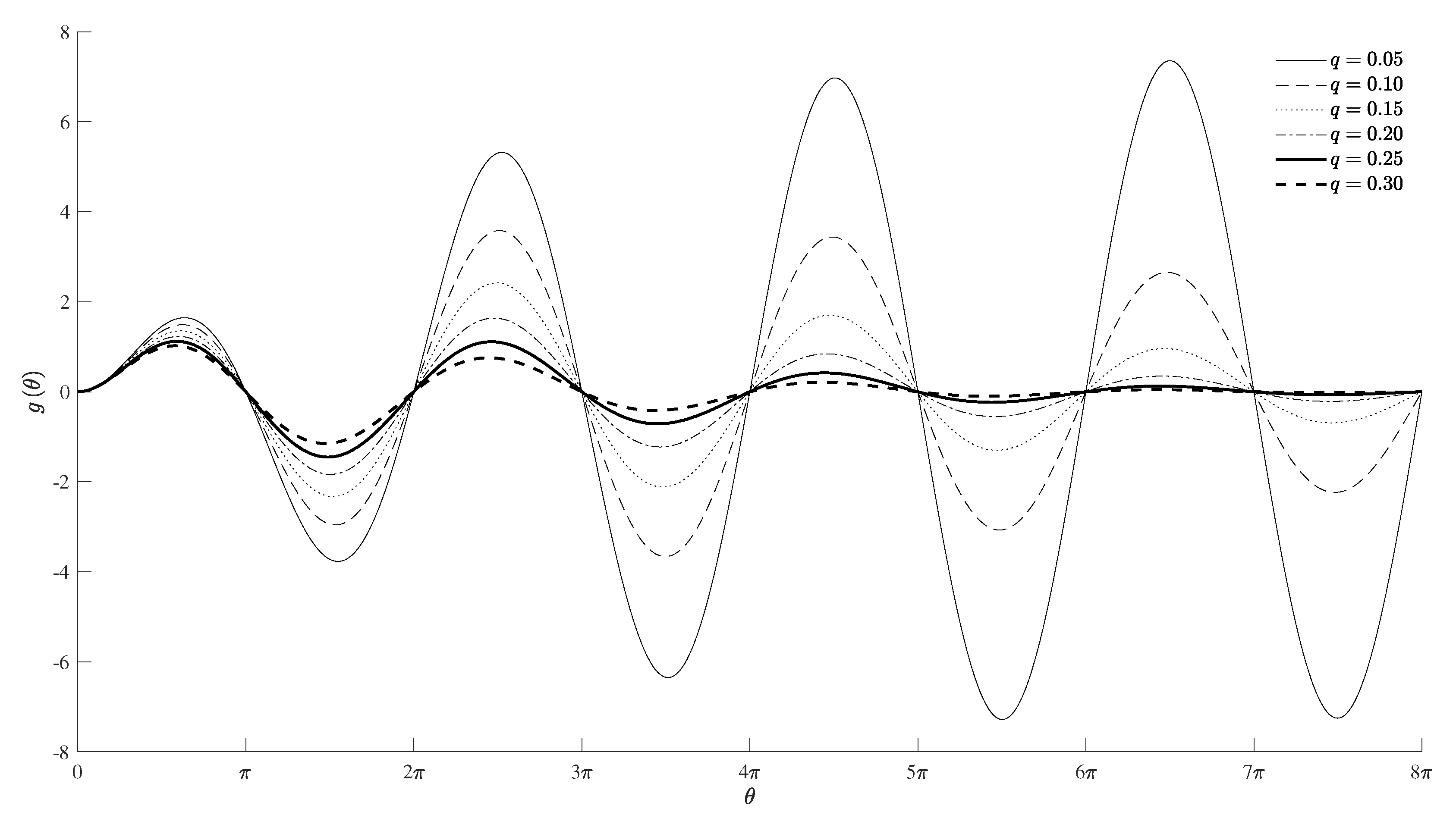
The time dependence (103) is illustrated in Figure 7 for several values of the parameter:
q = 0.05 , 0.10 , 0.15 , 0.20 , 0.25 , 0.30 .
The initial linear growth in θ is ultimately dominated by the exponential, with maximum at the root of:
0 = d g d θ = e q θ sin θ + θ + α cos θ q sin θ .
Thus the maximum is at
1 θ m + α = q sin θ m cos θ m sin θ m = q cot θ m .
Table 1 indicates for each value of (106) the values of θ m , corresponding to the time t m as fraction of the period:
t m τ = ω ˜ t m 2 π = θ m 2 π .
The peak amplitude at the time (109) is:
g θ m = θ m + α exp q θ m sin θ m .
The oscillation has a lower peak earlier as q increases, implying a reduction in the energy of oscillation.
Figure 7 illustrates the forced resonant oscillations (103) as a function of dimensionless time (101b) for different ratios (104) of damping to oscillation frequency. Resonance requires three conditions: (i) applied frequency equal to oscillation frequency (96); (ii) decay of the forcing equal to the damping (94a); (iii) matching (95a) of the phases of forcing β , damping ϕ and free oscillations α . The amplitude is given by (105). The oscillations with amplitude initially growing linearly with time are ultimately dominated by the exponential decay, sooner for larger decay.

6. Comparison of the Energies of Total and Free Oscillations

The total energy density (66) is the sum of kinetic and elastic energies. It may be averaged (69) over the length of the string. The time average over a period may be taken, not including a slowly decaying exponential term. The latter ensures a finite oscillation energy over all time (Section 6.1) that is compared between (a) the free damped oscillation and (b) the resonant forced oscillation with the same decay (Section 6.2).

6.1. Energy Averaged over Period and Length of String

The energy density (66) is given in terms of the dimensionless time (101b) by:
2 E x , θ = ρ ω ˜ 2 Y θ 2 + T Y x 2 .
The free oscillation corresponds to the first term in (93b):
Y ˜ x , θ = A sin k x e q θ cos θ ,
and the corresponding energy is:
2 E ˜ x , θ A 2 = e 2 q θ k 2 T cos 2 k x cos 2 θ + ρ ω ˜ 2 sin 2 k x sin θ + q cos θ 2 .
The spatial average (69) leads to:
2 A 2 E ˜ x , θ = e 2 q θ 2 ρ c 2 k 2 cos 2 θ + sin θ + q cos θ 2 ρ δ 2 sin θ + q cos θ 2 ,
that simplifies for weak damping δ 2 ω ˜ 2 k 2 c 2 or q 2 1 to:
e ˜ θ 4 E ˜ x , θ ρ c 2 k 2 A 2 = e 2 q θ 1 + q sin 2 θ .
The average over a period (77) leads to:
G ˜ θ e ˜ θ = e 2 q θ .
The total energy over all time of the damped oscillation is finite:
H ˜ 0 G ˜ θ d θ = 0 e 2 q θ d θ = 1 2 q = ω ˜ 2 δ ,
and larger for higher oscillation frequency and smaller damping. If there is no damping, δ 0 , the amplitude is constant and the energy is infinite over infinite time.
For the total oscillation, the forced oscillation (102) and (103) is added to the free oscillation (112):
Y x , θ = Y ˜ x , θ + Y ¯ x , θ = e q θ A cos θ + B θ + α sin θ sin k x .
Choosing opposite amplitudes, B = A , and setting α = 0 lead to:
Y x , θ = A sin k x e q θ cos θ θ sin θ .
The corresponding energy density is given by:
2 E x , θ A 2 = e 2 q θ T k 2 cos 2 k x cos θ θ sin θ 2 θ cos θ + 2 sin θ q cos θ θ sin θ 2 + ρ ω ˜ 2 sin 2 k x θ cos θ + 2 sin θ q cos θ θ sin θ 2 .
The weak damping approximation (64) implies q 2 1 in (104) and simplifies (120) to:
2 E x , θ ρ c 2 k 2 A 2 = e 2 q θ cos 2 k x cos θ θ sin θ 2 + sin 2 k x θ cos θ + 2 sin θ 2 2 q θ cos θ + 2 sin θ cos θ θ sin θ .
The spatial average (69) leads to:
e 2 q θ e θ 4 E x , θ ρ c 2 k 2 A 2 e 2 q θ = θ 2 + cos 2 θ + 4 sin 2 θ + θ sin 2 θ 2 q θ cos 2 θ 2 θ sin 2 θ + sin 2 θ θ 2 2 sin 2 θ .
The averages over a period are calculated in the Appendix A:
cos 2 θ = 1 2 = sin 2 θ ,
sin 2 θ = 0 ,
θ sin 2 θ = 1 2 ,
θ cos 2 θ = π 2 = θ sin 2 θ ,
θ 2 sin 2 θ = π .
Thus the average energy of the total oscillation is:
G θ = e θ = e 2 q θ θ 2 + 2 .
The total energy over all time is given by:
H 0 G θ d θ = I + 1 q ,
where:
I 0 θ 2 e 2 q θ d θ
is evaluated next to compare with the total energy of the free oscillation.

6.2. Total Energy of Total Oscillation over All Time

Noting the property:
q e 2 q θ = 2 θ e 2 q θ ,
the integral (126) is evaluated by:
I = 1 2 q 2 0 e 2 q θ d θ = 1 4 2 q 2 1 2 q = 1 4 q 3 .
Thus the energy of the total oscillation (125) is:
H = 1 4 q 3 + 1 q .
The ratio to the energy of the free oscillation (117) is:
J H H ˜ = 1 2 q 2 + 2 = ω ˜ 2 2 δ 2 + 2 = k 2 c 2 2 δ 2 + 2 = 2 k 2 χ 2 c 2 + 2
where we used (104), (96), and (15) in the weak damping approximation ω ˜ k c . Figure 8 shows as a function of 0.1 q 0.3 the energy over all time of the free oscillation (117), total oscillation (129), and their ratio (130).
The weak damping approximation (64) implies q 2 1 , which is satisfied by q < 0.3 . A positive value J > 0 in (130) requires:
1 2 q 2 + 2 > 0
which is met by all positive values of q and thus the results are consistent with the weak damping approximation. The suppression of damped free oscillations by resonant forcing at the same frequency (96) with opposite amplitude (94b), matched phase (95a), and decay equal to damping (94a), is limited because: (i) the forced oscillations have an amplitude initially increasing with time; (ii) the time decay is slow to limit the amplitude growth for weak decay equal to weak damping; (iii) the forced oscillation, in spite of starting at zero, may at intermediate times overwhelm the free oscillation, although both ultimately decay to zero; (iv) the final outcome may be that the energy over all time of the total oscillation may not be smaller, or indeed exceed the energy of the free oscillation for all time. This suggests the consideration of decaying forcing without resonance.

7. Non-Resonant and Resonant Forcing with Time Decay

The forcing of damped oscillations with the applied frequency equal to the oscillation frequency (96) leads to resonance (Section 5 and Section 6) if the decay rate of forcing equals the damping (94a). Making the latter distinct avoids resonance (Section 7.1) and the initially growing amplitude. This allows a comparison of the energy over all time of the total compared with the free oscillation for all ratios of forcing decay to damping (Section 7.2).

7.1. Matched Oscillations with Unequal Damping and Forcing Decay

The total oscillation (92) consists of the superposition of free oscillations with amplitude A, damping δ , oscillation frequency ω ˜ , and phase α , with the forced oscillations with amplitude c 2 F / E , decay ε , applied frequency ω ¯ , and phase β ϕ . If the oscillation ω ˜ and applied ω ¯ frequencies are distinct, the energies of the free and forced oscillations are added together, which is the opposite of the countering of the vibrations sought. Thus the oscillation and applied frequencies are assumed to be equal (96), and also choosing opposing amplitudes (93a), the total oscillation (92) simplifies to:
y ^ x , t = A sin k x e t δ cos ω ˜ t α e ε t cos ω ˜ t + β + ϕ .
Matching the phase (95a) leads to:
y ^ x , t = A sin k x e t δ e ε t cos ω ˜ t α ,
and the magnitude of the forcing (93a) is given by:
F = A δ ε c 2 δ ε 2 + 4 ω ¯ 2 1 / 2 ,
and simplifies for weak damping, δ 2 , ε 2 , ε δ ω ˜ 2 k 2 c 2 , and decay to:
F = 2 A ω ¯ c 2 δ ε = 2 A k c δ ε .
The case of resonance (Section 5 and Section 6) is excluded from (133) to (135) by having a forcing decay ε δ distinct from the damping.
The total, kinetic plus elastic, energy density (66) of the oscillation (133) is:
2 A 2 E ^ x , t = T k 2 cos 2 k x e t δ e ε t 2 cos 2 ω ˜ t α + ρ sin 2 k x ω ˜ e t δ e ε t sin ω ˜ t α + δ e t δ ε e ε t cos ω ˜ t α 2 .
Averaging over the length of the string (69) leads in the weak damping and decay approximation δ 2 , ε 2 , ε δ ω ˜ 2 k 2 c 2 to:
4 ρ c 2 k 2 A 2 E ^ x , t = e ^ t = e t δ e ε t 2 + 2 e t δ e ε t δ e t δ ε e ε t cos ω ˜ t α sin ω ˜ t α .
Averaging over a period (77), and using the results in the Appendix A, the second term on the right-hand side of (137) vanishes, leading to:
G ^ t e ^ t = e t δ e ε t 2 = e 2 t δ + e 2 ε t 2 e ε + δ t .

7.2. Comparison of the Free and Total Energies over All Time

The energy of the total oscillation over all time is:
H ^ 0 G ^ t d t = 1 2 δ + 1 2 ε 2 ε + δ ;
compared to the energy of the free oscillation:
H ˜ = 0 e 2 t δ d t = 1 2 δ ,
the ratio is:
H ^ H ˜ = 1 + δ ε 4 δ ε + δ = 1 δ ε 3 ε δ ε + δ .
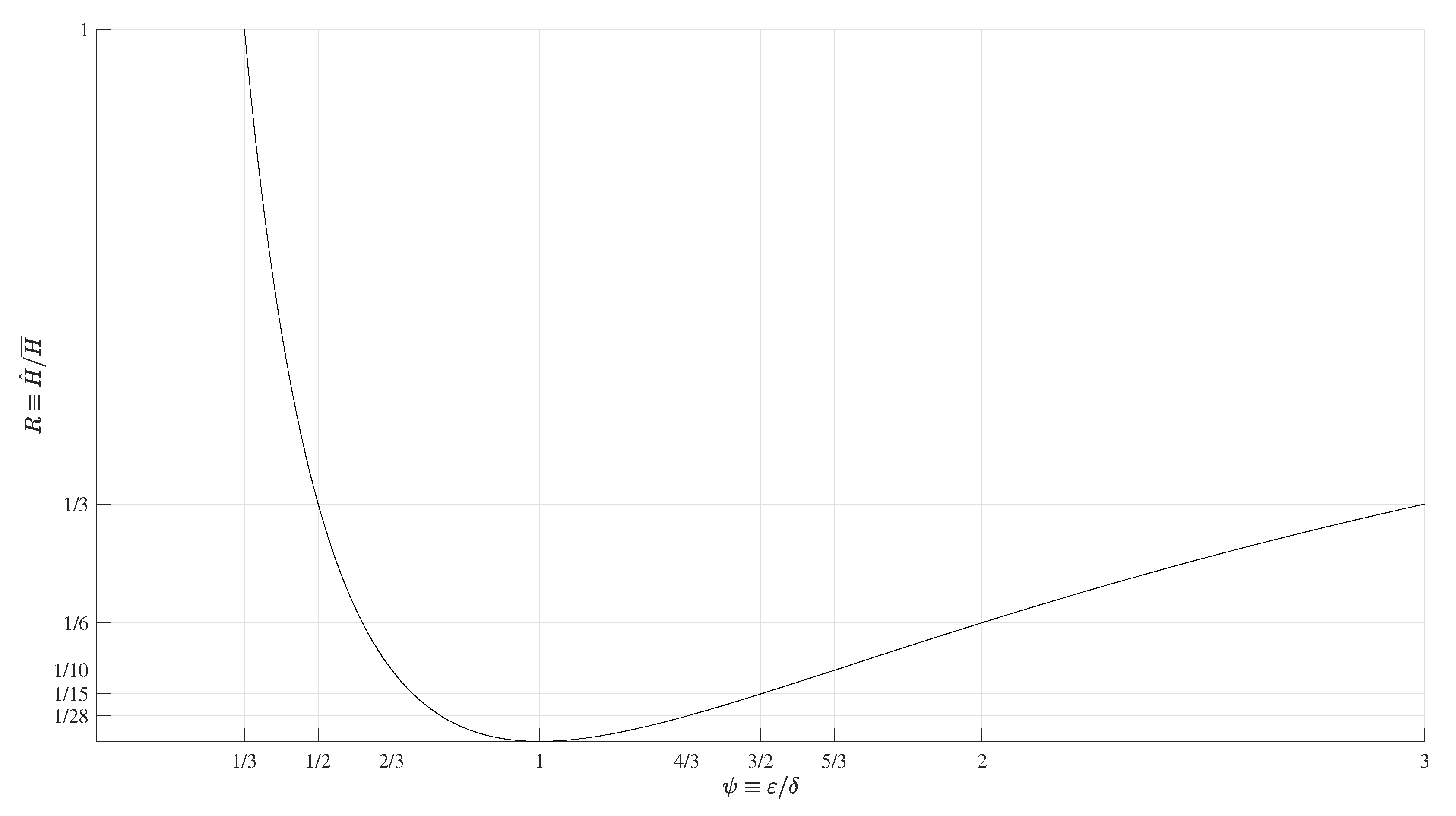
Thus the energy of the total oscillation is less than the energy of the free oscillation, H ^ < H ˜ , if the forcing decay exceeds one third of the damping, ε > δ / 3 . The ratio of energy for all time of the total to the free oscillation depends only on the ratio of damping to forcing decay, ψ ε / δ :
R ψ H ^ H ˜ = 1 1 ψ 3 ψ 1 ψ + 1 .
The ratio of energies must be positive, R > 0 , requiring 3 ψ 1 < ψ ψ + 1 . This last condition is always met for positive values of ψ , except ψ = 1 , since:
0 ψ 2 2 ψ + 1 = ψ 1 2 .
The extrema of the energy of total oscillation corresponds to ψ as a root of:
0 = d R d ψ = 2 ψ + 1 3 ψ 1 3 ψ ψ + 1 ψ 2 ψ + 1 2 ,
implying:
0 = 3 ψ 2 2 ψ 1 = ψ ψ + ψ ψ ;
the two roots are:
ψ ± = 1 ± 2 3 = 1 3 , 1 ;
Consequently: (i) the negative root is unphysical since the ratio of decays ψ must be positive, ψ > 0 , in (142) and the negative root would lead to R ψ = 8 < 0 ; (ii) the positive root marginally meets the condition R 0 and leads to:
R ψ + = 0
which would be a minimum with zero energy, but is actually invalid because it is the resonant case ε = δ when (133) does not apply. Thus, forcing decay should not be too close to the damping and moderate deviations lead to values of ψ with energy reduction as seen in the plot of R ψ in Figure 9 and is confirmed by the nine particular values indicated in Table 2.
The case ε = δ corresponds to resonance (Section 5 and Section 6) so the value R = 0 of zero total energy in (146b) for ψ + = 1 in (146a) is excluded and has similarities and differences to “beats”, (100a), (100b), when the applied frequency is close to the oscillation frequency, (99a) to (99d). When the forcing decay is close to the damping, the factor in curved brackets in (133) becomes:
e t δ e ε t = ε δ t + O ε 2 δ 2 t 2 ,
and to the leading order, there is, using (135), an amplitude growth linear on time:
y ¯ x , t = A ε δ t sin k x cos ω ˜ t α = F c 2 k t sin k x cos ω ˜ t α ,
which is typical of resonance. Values of ε not too close to δ are valid in (133) and lead to the results indicated in Table 2. Figure 9 shows the ratio of the energy of the total oscillation to the energy of the free oscillation as a function of the ratio of the forcing decay ε to the damping δ . For example, a forcing decay equal to 4 / 3 of the damping reduces the total energy over all time to 3.6 % of the energy of the free oscillation:
ψ e ε δ = 4 3 R ψ e = 0.036 .
These values of the forcing decay ε and damping δ in (148a) are sufficiently different:
ε δ = ψ e 1 δ = δ 3 = 1 1 ψ e ε = ε 4 ,
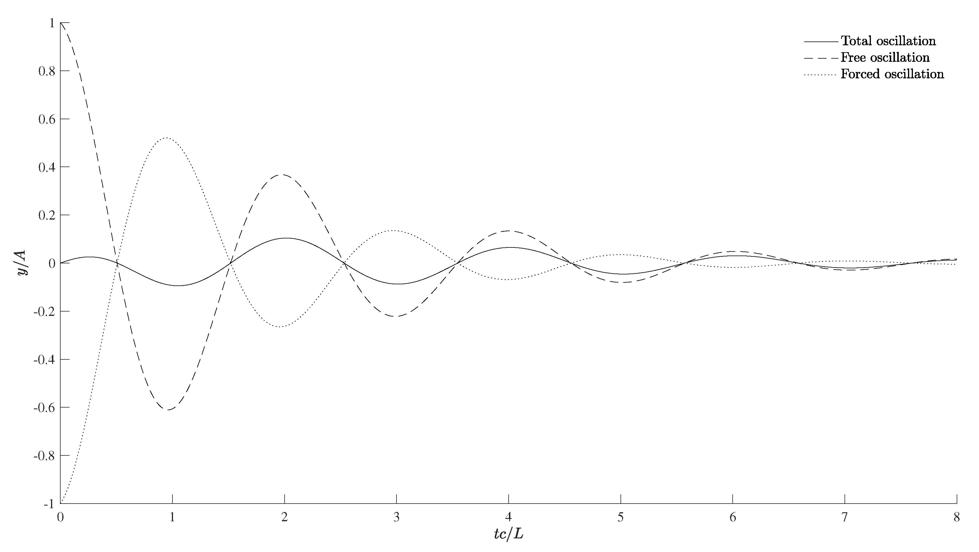
to be far from resonance ε = δ . Figure 10 shows that the oscillation is nearly suppressed by the forced oscillation for all times, including the first few periods when damping and forcing decay have not significantly reduced the oscillation.
The substantial reduction of the energy of oscillation, corresponding to a significant partial suppression of the free oscillation for an intermediate decay of forcing can be explained as follows: (i) if the decay of forcing is much smaller than the damping, ε < ψ e δ , the forced oscillation decays slowly, and dominates the faster damped free oscillation; (ii) if the decay of the forcing is much larger than the damping, ε > ψ e δ , the forced oscillation decays too quickly to counter the energy of the free oscillation; (iii) the effective forcing decay ε = ψ e δ is such that it extracts most energy from the free damped oscillation by decaying neither too slow (adds energy) or too fast (small effect). Thus, of the six strategies for suppression of free oscillations (Table 4), the most effective, with over 96% reduction, for ψ e = ε / δ = 4 / 3 or ε = 4 δ / 3 in Table 2, is forcing: (i) applied equal to oscillation frequency (96); (ii) applied phase (95a) equal to the sum of free oscillation phase (26b), and damping phase (32b); (iii) forcing with exponential time decay at the fraction 4 / 3 of the damping; (iv) amplitude of the forcing F related to the amplitude of the free oscillation A by (135):
F A = 2 k δ ε = 2 k δ 1 ψ e = k c 2 χ 1 4 3 = k c 2 3 χ .
Values of the forcing decay closer to the damping (Table 3) would lead to greater reductions of the total energy relative to the energy of free oscillation, at the risk of triggering resonance, which would render the result invalid. In order to avoid excessive proximity to resonance, the choice (148a), (148b), (149), of effective forcing decay 4 / 3 of the damping may be a safe compromise. A closer proximity to resonance may be possible depending on (i) the accuracy of the determination of the damping and (ii) the precision of application of the forcing decay, bearing in mind that the margins of error in both (i) and (ii) should not lead to an overlap.
The sixth most effective strategy of countering free oscillations is compared next (Section 8) with the five preceding strategies (Table 5).

8. Strategies for Partial Vibration Suppression

The usual method of active vibration suppression is to add to the oscillation (27) another out-of-phase by half a period:
y ˇ x , t = A exp t δ exp i k x ω t + τ 2 α = A exp t δ exp i k x ω t ω τ 2 i α = A exp t δ exp i k x ω t i π i α = A exp t δ exp i k x ω t α = y ˜ x , t ,
so that the sum is zero. This is best done by inserting through the boundary the opposite oscillation (150) to cancel (27). The opposite oscillation has: (i) the same wavenumber k; (ii) the same frequency ω ; (iii) the same amplitude A; and (iv) the opposite phase. The question of whether the “opposite” oscillation can be generated by forcing can be posed in the non-dissipative (part I) and dissipative (part II) cases, where it is shown that perfect cancellation is not possible. The question can be relaxed to the question of whether the addition of a forced oscillation can lead to a total energy less than that of the free oscillation. The answer is that this can be achieved with the constraints that are mentioned next. Six cases, I to VI, of partial vibration suppression, using (Table 5) forced oscillations to counter free oscillations, have been considered and evaluated comparing (Table 4) the energy of the total oscillation with that of the free oscillation.
The first four strategies, I–IV, are standard combinations of undamped or damped free oscillations with non-resonant and resonant forcing, and lead at best to a 75% reduction in energy. Two novel strategies, V–VI, are resonant and non-resonant forcing with magnitude decaying in time, and can lead to an energy reduction of over 96% Table 5. These six strategies, I–VI, are discussed briefly as a conclusion.
Starting with the non-dissipative case, the free oscillations are sinusoidal with constant amplitude. In the absence of damping, the (case I) non-resonant forced oscillations have a constant amplitude and different frequency from free oscillation and do not interact; thus, the energies of the free and forced oscillations add, which is the opposite of what was intended. The (case II) resonant forced oscillations have the same frequency as the free oscillations, but their amplitude increases linearly with time, thus eventually increasing the energy of the total oscillation. Considering a limited time span, say the first period of oscillation, it is possible to optimize the forcing to bring the total energy below that of the free oscillation by 75% at most.
Turning to the dissipative case, the free oscillations are sinusoidal in space-time with amplitude decaying exponentially with time due to damping. The (case III) dissipative non-resonant forcing involves a different frequency, a constant amplitude and a phase shift, which prevent perfect cancellation. The (case IV) dissipative resonant forcing involves the same frequency, and a constant amplitude, and there is a phase shift of π / 2 , again not allowing perfect cancellation. Furthermore, the decaying free oscillation is eventually dominated by the forced oscillation with constant amplitude both in the non-resonant and resonant cases, so the total energy increases in both cases of forcing for a sufficiently long time. In the resonant case, the forced oscillation is 90 degrees out-of-phase to the free oscillation, which tends to increase the total energy, but may be countered by a forcing phase.
Thus, there are four standard cases for the evolution of total energy as a function of time:
Undamped non-resonant forcing (case I): the free and forced oscillations have constant amplitude and different frequencies, so the energies are constant and added; the total energy increases and is independent of time;
Undamped resonant forcing (case II): the free oscillation has constant amplitude and is ultimately dominated by the forced oscillation that is out-of-phase and has an amplitude increasing linearly with time; optimized forcing may reduce the total energy over the first period (concentrated forces) or somewhat longer (distributed forces) before being overwhelmed by the energy of the forced oscillation growing such as the square of time; the highest possible energy reduction is 75% over the first period using distributed forcing optimized along the string; this favorable result is lost for times significantly exceeding one period, because for the forced resonant oscillation the amplitude increases linearly with time and the energy as the square;
Damped non-resonant forcing (case III): the free oscillation decays exponentially due to damping and is dominated by the forced oscillation with constant amplitude; since the natural and applied frequencies are different, the energies of the free and forced oscillation add, with the former decaying relative, to the latter; thus the decay of the free oscillation is overwhelmed by the non-decaying forced oscillation, which is counter productive;
Damped resonant forcing (case IV): although the natural and applied frequencies coincide, there is again the contrast between the free oscillations decaying exponentially in time and the forced oscillations out-of-phase and with constant amplitude; even optimizing the forcing to counter the free oscillation, the total energy is ultimately dominated by the forced oscillation, which is counter productive as in case III.
Since none of the standard cases I–IV are very effective at countering free oscillations over time for several periods, two novel cases V–VI are introduced. They apply to damped free oscillations and use forcing that decays in time. It is possible to consider: (i) opposing amplitudes of the free and forced oscillations; (ii) matched phases; (iii) equal oscillation and applied frequencies. The case of forcing decay equal to damping (case V) leads to resonance with the forcing causing an amplitude growing linearly with time, but ultimately dominated by the exponential time decay. This is less favorable than having distinct forcing decay and damping (case VI) for which both the energy of the free and forced oscillation are finite when integrated over all time. Tuning the decay of the forcing to a suitable fraction of the damping, ψ e = ε / δ = 4 / 3 , the total energy can be reduced, R ψ e = 0.036 , by more than 96%. This case is represented by Figure 10, which provides a graphic display of how the forced oscillation counters the free oscillation in an effective way, leading to substantial reduction or almost suppression, in the first few periods of oscillation, before the ultimate damping and decay for long time.
The consideration of forcing with non-constant amplitude suggests a generalized definition of resonance (Section 9).

9. A Generalized Definition of Resonance

The usual concept of resonance in its simplest terms can be considered for the classical wave Equation (4) with free wave solution (21) without damping δ = 0 for one mode:
y ˜ x , t = A sin k x cos k c t α ,
with amplitude A, wavenumber k, frequency ω ˜ = k c and phase shift α . The forcing with a generally distinct applied frequency ω ¯ , but with a same phase shift α , and with any amplitude F spatially distributed with the same wavenumber k:
2 y ¯ t 2 c 2 2 y ¯ x 2 = F sin k x cos ω ¯ t α ,
leads to distinct solutions in two cases. The non-resonant case of applied frequency ω ¯ distinct from the natural frequency ω ˜ = k c has the constant amplitude and the same phase:
y ¯ x , t = F c 2 k 2 ω ¯ 2 sin k x cos ω ¯ t α ,
but does not hold for ω ¯ = ± k c . The latter is the resonant case:
2 y ¯ t 2 c 2 2 y ¯ x 2 = F sin k x cos k c t α ,
leading to oscillations with amplitude increasing linearly with time:
y ¯ x , t = F 2 k c t sin k x sin k c t α ,
and with a phase shift of π / 2 . This suggests two definitions of “resonance”: (A) the usual “physical” definition of applied frequency ω ¯ equal to natural frequency; (B) the equivalent “mathematical” definition that the amplitude grows linearly with time. It is shown next that (B) is the more general definition, by considering a more general case.
Consider: (i) instead of the classical wave Equation (4), the wave-diffusion or telegraph Equation (2); (ii) instead of forcing (152) with same wavenumber k and applied frequency ω ¯ , a forcing (84) with also a generally distinct phase shift β and an amplitude F decaying exponentially with time at a decay rate ε . Now there are four forcing parameters (Table 4) and the resonance, in the sense of amplitude of forced oscillation initially growing linearly with time (98), requires three conditions: (i) applied frequency equal (96) to the oscillation frequency (16), which is the natural frequency k c modified by damping; (ii) matching (95a) of the phases of the forcing β in (84), of the free oscillation α in (19b) and of the damping ϕ in (32b); (iii) exponential decay ε of the forcing in (84) equal (94a) to the damping (15); (iv) matching of free A and forced F amplitudes (93a). Clearly the definition A of equal oscillation and applied frequencies, corresponding to one condition (i), is not sufficient to have oscillation with amplitude initially growing with time, because other conditions are needed as well.
This suggests the following definition of resonance: resonant forcing leads to oscillations with an amplitude initially increasing with time, and requires the matching of all parameters of forcing with those of the free oscillation, namely (Table 4): (i) the applied frequency must equal the free oscillation frequency; (ii) the forcing phase plus the damping phase must equal the phase of the free oscillation; (iii) the damping of the free oscillation must be matched by the exponential decay in time of the forcing. The linear growth with time of the forced oscillations for short time may be ultimately dominated by damping. To prevent resonance, it is sufficient to break one of the three conditions (i) to (iii) above. The most effective strategy VI for the suppression of free damped oscillation is: ( α ) to keep (i) applying equal to natural frequency and (ii) match applied, damping, and free phases; ( β ) avoid resonance by a forcing decay different from damping, being selected to substantially decrease the total energy (Table 2 and Figure 9); ( γ ) choose opposite amplitudes for the forced and free oscillations. Choosing ( β ) a forcing decay ε related to damping δ by ψ e = ε / δ = 4 / 3 in Table 2 reduces the total energy of oscillation over all time to 3.6% of the energy of the free oscillation, (148a) and (148b), and nearly suppresses the free oscillation (Figure 10) in the critical first periods before damping and decay take over.

10. Conclusions

The present paper has considered forcing as a physical mechanism to reduce the energy of free transverse oscillations of an elastic string with two contrasting results: (part I) limited effectiveness in all cases for undamped oscillations, which is a “negative” but genuine result, indicating the limitations arising from laws of physics; (part II) good effectiveness for damped oscillations using decaying forcing, which is a “desirable” result compatible with the laws of physics. The implementation of the forcing that is most effective is a follow-up problem that is not addressed here, as the results of the present paper provide the objective. The implementation of forcing decaying exponentially in time should be simple and well within the capabilities of control systems using actuators, sensors, and processing.
The main difference between the two parts of the present paper is that paper I deals with undamped and paper II with damped oscillations, hence the two papers deal with different equations, namely wave equation in paper I and wave-diffusion equation in paper II. The paper II considers only continuously distributed forces, whereas paper I considers also forcing at a single point and forcing at multiple points. Both papers comprehensively cover non-resonant and resonant forcing with constant amplitude, with significant differences between the two undamped cases in paper I and the four damped cases in paper II. Since forcing with constant amplitude is of limited effectiveness in partial vibration suppression, paper II considers forcing with amplitude decaying exponentially in time. The assessment of the effectiveness of partial vibration suppression is assessed by comparing the energy of the free vibration with the energy of the total, free plus forced, oscillation; this is done for all cases of undamped (part I) and damped (part II) oscillations, resulting in somewhat extensive calculations.
The calculations in the present paper are extensive because there are five cases to consider: (i) damped free oscillations (Section 2); (ii–iii) oscillations forced with constant amplitude without and with resonance (Section 3 and Section 4) including associated energies (Section 6); and (iv–v) oscillations forced with amplitude decaying exponentially with time in resonant and non-resonant cases (Section 6 and Section 7), including associated energies that are relevant to a comparison of strategies for partial vibration suppression (Section 8). This leads to a generalized definition of resonance (Section 9) before the conclusion (Section 10). The novel features of this paper are outlined in the introduction (Section 1).
The four key elements for effective vibration suppression are the following: (i) the applied frequency equals the natural frequency so that the forced oscillation can be kept at all times in opposition to the free oscillation; (ii) the free and forced oscillations will be in opposition at all time if the phases of the free oscillation and forcing are matched at the initial time, taking into account the phase associated with damping; (iii) the amplitude of the forced oscillation equals that of the free oscillation with opposite sign or phase at initial time; (iv) the forcing decays exponentially in time at a rate “close to but not equal to” the damping, because: (iv–a) if the forcing decay equals the damping, there is resonance, and the amplitude grows initially in time linearly, adding energy that is eventually dissipated, and failing to suppress oscillations in the near term; (iv–b) if the forcing decay is very different from the damping, one of the free and forced oscillations decays much faster than the other, preventing effective vibration suppression; (iv–c) a forcing decay “not equal to” the damping avoids resonance (iv–a), and being “close to” the damping allows a comparable decay in time (iv–b), so that partial vibration suppression (i–iii) is effective over time until both the free and forced oscillations become negligible.
In conclusion, free damped oscillations have a finite energy E 0 over infinite time due to damping. The forced oscillation with exponential decay in time also has finite energy E over all time due to decay. Partial vibration suppression reduces the total energy to E 0 E by keeping the free and forced oscillations out-of-phase. This requires (i) equal free and applied frequencies, (ii) matching of free, forced, and damping phases, and (iii) equal initial amplitudes with opposite signs or phases. The forcing decay and damping should not be equal to avoid resonance, but may be close enough to lead to suppression of more than 90% of the energy of vibration. The verification of this theoretical prediction of the most effective strategy for the partial vibration suppression can be subject to experimental demonstration, which is beyond the scope of the present paper.
The applications of the present theory of partial vibration suppression are undamped systems described by the classical wave equation (part I) and damped systems described by the wave-diffusion or telegraph equation (part II). The wave equation applies to acoustic, elastic, and electromagnetic waves, and the damping effects can be thermal conduction or radiation, viscosity, electrical resistance and mass diffusion. The most effective method of reduction of vibration energy by more than 90% is forcing at the natural frequency with amplitude decaying exponentially with time, and applies not only to continuous systems, but also to discrete systems such as: (i) mechanical oscillators consisting of masses, springs, dampers, and forcing actuators; (ii) electrical circuits consisting of inductors, capacitors, and resistors powered by batteries; (iii) analogous circuits in acoustics, hydraulics, and other fields.

Author Contributions

Conceptualization, L.M.B.C.C.; Methodology, L.M.B.C.C. and M.J.S.S.; Software, M.J.S.S.; Formal analysis, L.M.B.C.C. and M.J.S.S.; Investigation, L.M.B.C.C. and M.J.S.S.; Resources, L.M.B.C.C.; Writing—original draft, L.M.B.C.C.; Writing—review and editing, L.M.B.C.C. and M.J.S.S.; Visualization, M.J.S.S. All authors have read and agreed to the published version of the manuscript.

Funding

This work was supported by the Fundação para a Ciência e a Tecnologia (FCT), Portugal, through Institute of Mechanical Engineering (IDMEC), under the Associated Laboratory for Energy, Transports and Aeronautics (LAETA), whose grant numbers are SFRH/BD/143828/2019 to M.J.S. Silva and UIDB/50022/2020.

Institutional Review Board Statement

Not applicable.

Informed Consent Statement

Not applicable.

Data Availability Statement

Not applicable.

Conflicts of Interest

The authors declare no conflict of interest.

Appendix A. Averages over a Period

In (123a) to (123e) we used the following averages:
sin 2 θ , cos 2 θ = 1 2 π 0 2 π sin 2 θ , cos 2 θ d θ = 1 4 π cos 2 θ , sin 2 θ 0 2 π = 0 ,
cos 2 θ , sin 2 θ = 1 2 ± 1 2 cos 2 θ = 1 2 ,
θ sin 2 θ = 1 2 π 0 2 π θ sin 2 θ d θ = 1 4 π θ cos 2 θ 0 2 π + 1 4 π 0 2 π cos 2 θ d θ = 1 2
θ sin 2 θ , cos 2 θ = 1 2 π 0 2 π θ sin 2 θ , cos 2 θ d θ = 1 4 π 0 2 π θ θ cos 2 θ d θ = 2 π 2 8 π 1 8 π θ sin 2 θ 0 2 π ± 0 2 π sin 2 θ d θ = π 2 ,
θ 2 sin 2 θ = 1 2 π 0 2 π θ 2 sin 2 θ d θ = 1 4 π θ 2 cos 2 θ 0 2 π + 1 2 π 0 2 π θ cos 2 θ d θ = 2 π 2 4 π + 1 4 π θ sin 2 θ 0 2 π 1 4 π 0 2 π sin 2 θ d θ = π .

References

  1. Strutt, J.W.; Lindsay, R.B. The Theory of Sound, 2nd ed.; Dover Publications, Inc.: New York, NY, USA, 1945; Volume 1–2. [Google Scholar]
  2. Morse, P.M.; Ingard, K.U. Theoretical Acoustics; International Series in Pure and Applied Physics; McGraw-Hill Book Company: New York, NY, USA, 1968. [Google Scholar]
  3. Pierce, A.D. Acoustics: An Introduction to Its Physical Principles and Applications, 3rd ed.; Springer International Publishing: Cham, Switzerland, 2019. [Google Scholar] [CrossRef]
  4. Strutt, J.W. The Problem of the Whispering Gallery. London Edinburgh Dublin Philos. Mag. J. Sci. 1910, 20, 1001–1004. [Google Scholar] [CrossRef] [Green Version]
  5. Lighthill, M.J. Waves in Fluids, 1st ed.; Cambridge University Press: Cambridge, UK, 1978. [Google Scholar]
  6. Campos, L.M.B.C. On waves in gases. Part I: Acoustics of jets, turbulence, and ducts. Rev. Mod. Phys. 1986, 58, 117–182. [Google Scholar] [CrossRef]
  7. Campos, L.M.B.C. On 36 Forms of the Acoustic Wave Equation in Potential Flows and Inhomogeneous Media. Appl. Mech. Rev. 2007, 60, 149–171. [Google Scholar] [CrossRef]
  8. Nelson, P.A.; Elliott, S.J. Active Control of Sound, 1st ed.; Academic Press: London, UK, 1992. [Google Scholar]
  9. Campos, L.M.B.C.; Lau, F.J.P. On Active Noise Reduction in a Cylindrical Duct with Flow. Int. J. Acoust. Vib. 2009, 14, 150–162. [Google Scholar] [CrossRef]
  10. Love, A.E.H. A Treatise on the Mathematical Theory of Elasticity, 4th ed.; Dover Books on Engineering; Dover Publications, Inc.: New York, NY, USA, 1944. [Google Scholar]
  11. Timoshenko, S.P.; Monroe, J.G. Theory of Elastic Stability, 2nd ed.; McGraw-Hill Book Company, Inc.: New York, NY, USA, 1961. [Google Scholar]
  12. Prescott, J. Applied Elasticity, 1st ed.; Dover Publications: New York, NY, USA, 1946. [Google Scholar]
  13. Muskhelishvili, N.L. Some Basic Problems of the Mathematical Theory of Elasticity. Basic Equations, the Plane Theory of Elasticity, Torsion and Bending, 5th ed.; Nauka: Moscow, Russia, 1966. [Google Scholar]
  14. Landau, L.D.; Lifshitz, E.M. Theory of Elasticity, 2nd ed.; Course of Theoretical Physics; Pergamon Press Ltd.: Oxford, UK, 1970; Volume 7. [Google Scholar]
  15. Lekhnitskii, S.G. Theory of Elasticity of an Anisotropic Elastic Body; Mir Publishers: Moscow, Russia, 1981. [Google Scholar]
  16. Rekach, V.G. Manual of the Theory of Elasticity, 1st ed.; Mir Publishers: Moscow, Russia, 1979. [Google Scholar]
  17. Parton, V.Z.; Perline, P.I. Méthodes de la Théorie Mathématique de L’élasticité; Éditions Mir: Moscow, Russia, 1984; Volume 2. [Google Scholar]
  18. Antman, S.S. Nonlinear Problems of Elasticity, 1st ed.; Applied Mathematical Sciences; Springer Science+Business Media: New York, NY, USA, 1995; Volume 107. [Google Scholar] [CrossRef]
  19. Campos, L.M.B.C. Transcendental Representations with Applications to Solids and Fluids, 1st ed.; Mathematics and Physics for Science and Technology; CRC Press: Boca Raton, FL, USA, 2012; Volume 2. [Google Scholar] [CrossRef]
  20. Campos, L.M.B.C. Higher-Order Differential Equations and Elasticity, 1st ed.; Mathematics and Physics for Science and Technology; CRC Press: Boca Raton, FL, USA, 2019; Volume 4. [Google Scholar] [CrossRef]
  21. Kirchhoff, G. Ueber die Transversalschwingungen eines Stabes von veränderlichem Querschnitt. Ann. Der Phys. 1880, 246, 501–512. [Google Scholar] [CrossRef] [Green Version]
  22. Ono, A. Lateral vibrations of tapered bars. J. Soc. Mech. Eng. 1925, 28, 429–441. [Google Scholar] [CrossRef]
  23. Gaines, J.H.; Volterra, E. Transverse Vibrations of Cantilever Bars of Variable Cross Section. J. Acoust. Soc. Am. 1966, 39, 674–679. [Google Scholar] [CrossRef]
  24. Wang, H.C. Generalized Hypergeometric Function Solutions on the Transverse Vibration of a Class of Nonuniform Beams. J. Appl. Mech. 1967, 34, 702–708. [Google Scholar] [CrossRef]
  25. Naguleswaran, S. Vibration of an Euler-Bernoulli beam of constant depth and with linearly varying breadth. J. Sound Vib. 1992, 153, 509–522. [Google Scholar] [CrossRef]
  26. Downs, B. Transverse Vibrations of Cantilever Beams Having Unequal Breadth and Depth Tapers. J. Appl. Mech. 1977, 44, 737–742. [Google Scholar] [CrossRef]
  27. Zhou, D.; Cheung, Y.K. The free vibration of a type of tapered beams. Comput. Methods Appl. Mech. Eng. 2000, 188, 203–216. [Google Scholar] [CrossRef]
  28. Cazzani, A.; Rosati, L.; Ruge, P. The contribution of Gustav R. Kirchhoff to the dynamics of tapered beams. Z. Für Angew. Math. Und Mech. 2017, 97, 1174–1203. [Google Scholar] [CrossRef] [Green Version]
  29. Wang, C.Y. Vibration of a tapered cantilever of constant thickness and linearly tapered width. Arch. Appl. Mech. 2013, 83, 171–176. [Google Scholar] [CrossRef]
  30. Campos, L.M.B.C.; Marta, A.C. On the prevention or facilitation of buckling of beams. Int. J. Mech. Sci. 2014, 79, 95–104. [Google Scholar] [CrossRef]
  31. Campos, L.M.B.C.; Marta, A.C. On The Vibrations of Pyramidal Beams With Rectangular Cross-Section and Application to Unswept Wings. Q. J. Mech. Appl. Math. 2021, 74, 1–31. [Google Scholar] [CrossRef]
  32. Campos, L.M.B.C.; Silva, M.J.S. On the Countering of Free Vibrations by Forcing: Part I–Non-Resonant and Resonant Forcing with Phase Shifts. Appl. Mech. 2022, 3, 1352–1384. [Google Scholar] [CrossRef]
  33. Landau, L.D.; Lifshitz, E.M. Fluid Mechanics, 2nd ed.; Course of Theoretical Physics; Pergamon Press: Oxford, UK, 1987; Volume 6. [Google Scholar]
  34. Lamb, H. Hydrodynamics, 6th ed.; Dover Publications, Inc.: New York, NY, USA, 1945. [Google Scholar]
  35. Batchelor, G.K. An Introduction to Fluid Dynamics; Cambridge Monographs on Mechanics and Applied Mathematics; Cambridge University Press: Cambridge, UK, 1967. [Google Scholar]
  36. Bateman, H. The Mathematical Analysis of Electrical and Optical Wave-Motion on the Basis of Maxwell’s Equations; Cambridge University Press: Cambridge, UK, 1915. [Google Scholar]
  37. Rutherford, D.E. Fluid dynamics, 1st ed.; University Mathematical Texts, Oliver and Boyd: Edinburgh, UK, 1959. [Google Scholar]
  38. Duncan, W.J.; Thom, A.S.; Young, A.D. Mechanics of fluids, 2nd ed.; Edward Arnold: London, UK, 1970. [Google Scholar]
  39. Loitsyanskii, L.G. Mechanics of Liquids and Gases, 2nd ed.; International Series of Monographs in Aeronautics and Astronautics; Pergamon Press: Oxford, UK, 1966; Volume 6. [Google Scholar]
  40. Dyke, M.V. Perturbation Methods in Fluid Mechanics; The Parabolic Press: Stanford, CA, USA, 1975. [Google Scholar]
  41. Dyke, M.V. An Album of Fluid Motion; The Parabolic Press: Stanford, CA, USA, 1982. [Google Scholar]
  42. Lighthill, M.J. An Informal Introduction to Theoretical Fluid Mechanics; The Institute of Mathematics and Its Applications Monograph; Oxford University Press: Oxford, UK, 1986; Volume 2. [Google Scholar]
  43. Schlichting, H.; Gersten, K. Grenzschicht-Theorie, 10th ed.; Martinus Nijhoff Publishers: Dordrecht, The Netherlands, 2006. [Google Scholar] [CrossRef]
  44. Young, A.D. Boundary Layers; AIAA Education Series; American Institute of Aeronautics & Astronautics, Inc.: Reston, VA, USA, 1989. [Google Scholar]
  45. Lin, C.C. The Theory of Hydrodynamic Stability; Cambridge Monographs on Mechanics and Applied Mathematics; Cambridge University Press: Cambridge, UK, 1955. [Google Scholar]
  46. Drazin, P.G.; Reid, W.H. Hydrodynamic Stability, 2nd ed.; Cambridge Mathematical Library; Cambridge University Press: Cambridge, UK, 2004. [Google Scholar]
  47. Sokolnikoff, I.S. Mathematical Theory of Elasticity, 2nd ed.; McGraw-Hill Book Company: New York, NY, USA, 1956. [Google Scholar]
  48. Prager, W. Introduction to Mechanics of Continua; Dover Publications, Inc.: Mineola, NY, USA, 1973. [Google Scholar]
  49. Timoshenko, S.P.; Goodier, J.N. Theory of Elasticity, 2nd ed.; Engineering Societies Monographs; McGraw-Hill Book Company: New York, NY, USA, 1951. [Google Scholar]
  50. Hill, R. The Mathematical Theory of Plasticity; Oxford University Press: Oxford, UK, 1950. [Google Scholar]
  51. Findley, W.N.; Lai, J.S.; Onaran, K. Creep and Relaxation of Nonlinear Viscoelastic Materials with an Introduction to Linear Viscoelasticity; Dover Publications, Inc.: New York, NY, USA, 1989. [Google Scholar]
  52. Rabotnov, Y.N. Elements of Hereditary Solid Mechanics; Mir Publishers: Moscow, Russia, 1980. [Google Scholar]
  53. Parton, V.Z.; Morozov, E.M. Elastic-Plastic Fracture Mechanics; Mir Publishers: Moscow, Russia, 1978. [Google Scholar]
  54. Eirich, F.R. Rheology Theory and Applications; Academic Press: New York, NY, USA, 1956–1969; Volume 1–5.
  55. Chandrasekharaiah, D.S.; Debnath, L. Continuum Mechanics; Academic Press, Inc.: San Diego, CA, USA, 1994. [Google Scholar]
  56. Duvaut, G. Mécanique des Milieux Continus; Masson: Paris, France, 1990. [Google Scholar]
  57. Goodier, J.N.; Hodge, P.G. Elasticity and Plasticity; Surveys in Applied Mathematics; John Wiley & Sons, Inc.: New York, NY, USA, 1958; Volume 1. [Google Scholar]
  58. Lin, T.H. Theory of Inelastic Structures; John Wiley & Sons, Inc.: New York, NY, USA, 1968. [Google Scholar]
  59. Sih, G.C.; Michopoulos, J.G.; Chou, S.C. Hygrothermoelasticity, 1st ed.; Springer: Dordrecht, The Netherlands, 1986. [Google Scholar] [CrossRef]
  60. Planck, M. Treatise on Thermodynamics, 5th ed.; Dover Publications, Inc.: New York, NY, USA, 1917. [Google Scholar]
  61. Fermi, E. Thermodynamics; Dover Publications, Inc.: New York, NY, USA, 1956. [Google Scholar]
  62. Guggenheim, E.A. Thermodynamics: An Advanced Treatment for Chemists and Physicists; Monographs on Theoretical and Applied Physics; North-Holland Publishing Co.: Amsterdam, The Netherlands, 1949; Volume 2. [Google Scholar]
  63. Callen, H.B. Thermodynamics: An Introduction to the Physical Theories of Equilibrium Thermostatics and Irreversible Thermodynamics; John Wiley & Sons, Inc.: New York, NY, USA, 1960. [Google Scholar]
  64. Tisza, L. Generalized Thermodynamics; The MIT Press: Cambridge, MA, USA, 1966. [Google Scholar]
  65. Prigogine, I. Introduction to Thermodynamics of Irreversible Processes, 3rd ed.; John Wiley & Sons, Inc.: Hoboken, NJ, USA, 1967. [Google Scholar]
  66. Truesdell, C.A. Rational Thermodynamics, 2nd ed.; Springer: New York, NY, USA, 1984. [Google Scholar] [CrossRef]
  67. De Groot, S.R.; Mazur, P. Non-Equilibrium Thermodynamics; Dover Publications, Inc.: New York, NY, USA, 1984. [Google Scholar]
  68. Lamé, G. Leçons sur la Théorie Analytique de la Chaleur; Mallet-Bachelier: Paris, France, 1861. [Google Scholar]
  69. Carslaw, H.S.; Jaeger, J.C. Conduction of Heat in Solids, 2nd ed.; Oxford Science Publications; Oxford University Press: Oxford, UK, 1959. [Google Scholar]
  70. Özışık, M.N. Boundary Value Problems of Heat Conduction; Dover Publications, Inc.: Mineola, NY, USA, 1989. [Google Scholar]
  71. Roberts, J.K. Heat and Thermodynamics, 3rd ed.; Blackie & Son: London, UK, 1941. [Google Scholar]
  72. Zemansky, M.W.; Dittman, R.H. Heat and Thermodynamics: An Intermediate Textbook, 7th ed.; The McGraw-Hill Companies, Inc.: New York, NY, USA, 1997. [Google Scholar]
  73. Campos, L.M.B.d.C.; Vilela, L.A.R. Vector Fields with Applications to Thermodynamics and Irreversibility, 1st ed.; Mathematics and Physics for Science and Technology; CRC Press: Boca Raton, FL, USA, 2022; Volume 5. [Google Scholar]
  74. Landau, L.D.; Lifshitz, E.M. Statistical Physics, 2nd ed.; Course of Theoretical Physics; Pergamon Press: Oxford, UK, 1969; Volume 5. [Google Scholar]
  75. Planck, M. The Theory of Heat Radiation, 2nd ed.; P. Blakiston’s Son & Co.: Philadelphia, PA, USA, 1914. [Google Scholar]
  76. Chandrasekhar, S. Radiative Transfer; Dover Books on Advanced Mathematics; Dover Publications, Inc.: New York, NY, USA, UK, 1960. [Google Scholar]
  77. Denbigh, K. The Principles of Chemical Equilibrium with Applications in Chemistry and Chemical Engineering, 4th ed.; Cambridge University Press: Cambridge, UK, 1997. [Google Scholar]
  78. Davies, J.T.; Rideal, E.K. Interfacial Phenomena, 2nd ed.; Academic Press: New York, NY, USA, 1963. [Google Scholar]
  79. Frank-Kamenetskii, D.A. Diffusion and Heat Exchange in Chemical Kinetics; Princeton University Press: Princeton, NJ, USA, 1955. [Google Scholar]
  80. Barrère, M.; Prud’Homme, R. Aérothermochimie des Écoulements Homogènes; Gauthier-Villars: Paris, France, 1971. [Google Scholar]
  81. Kuo, K.K.Y. Principles of Combustion, 2nd ed.; John Wiley & Sons, Inc.: Hoboken, NJ, USA, 2005. [Google Scholar]
  82. Candel, S. Mécanique des Fluides: Cours, 2nd ed.; Dunod: Paris, France, 2001. [Google Scholar]
  83. Poinsot, T.; Veynante, D. Theoretical and Numerical Combustion, 2nd ed.; R.T. Edwards, Inc.: Philadelphia, PA, USA, 2005. [Google Scholar]
  84. Campos, L.M.B.C.; Vilela, L.A.R. Compressible Flow with Applications to Engines, Shocks and Nozzles, 1st ed.; Mathematics and Physics for Science and Technology; CRC Press: Boca Raton, FL, USA, 2022; Volume 5. [Google Scholar]
  85. Landau, L.D.; Lifshitz, E.M. The Classical Theory of Fields, 4th ed.; Course of Theoretical Physics; Butterworth-Heinemann: Oxford, UK, 1980; Volume 2. [Google Scholar]
  86. Maxwell, J.C. A Treatise on Electricity and Magnetism, 1st ed.; Clarendon Press: Oxford, UK, 1873; Volume 1–2. [Google Scholar]
  87. Hertz, H. Electric Waves Being Researches on the Propagation of Electric Action with Finite Velocity through Space; Dover Books on History of Science and Classics of Science; Dover Publications, Inc.: New York, NY, USA, 1962. [Google Scholar]
  88. Jeans, J.H. The Mathematical Theory of Electricity and Magnetism, 2nd ed.; Cambridge University Press: Cambridge, UK, 1911. [Google Scholar]
  89. Stratton, J.A. Electromagnetic Theory; International Series in Pure and Applied Physics; McGraw-Hill Book Company, Inc.: New York, NY, USA, 1941. [Google Scholar]
  90. Jones, D.S. The Theory of Electromagnetism; Pergamon Press: Oxford, UK, 1964. [Google Scholar]
  91. Slater, J.C.; Frank, N.H. Electromagnetism; Dover Publications, Inc.: New York, NY, USA, 1969. [Google Scholar]
  92. Campos, L.M.B.C. Generalized Calculus with Applications to Matter and Forces, 1st ed.; Mathematics and Physics for Science and Technology; CRC Press: Boca Raton, FL, USA, 2014; Volume 3. [Google Scholar] [CrossRef]
  93. Landau, L.D.; Lifshitz, E.M. Mechanics, 3rd ed.; Course of Theoretical Physics; Butterworth-Heinemann: Oxford, UK, 1976; Volume 1. [Google Scholar]
  94. Mathieu, É.L. Dynamique Analytique; Gauthier-Villars: Paris, France, 1878. [Google Scholar]
  95. Routh, E.J. A treatise on Dynamics of a Particle with Numerous Examples; Cambridge University Press: Cambridge, UK, 1898. [Google Scholar]
  96. Whittaker, E.T. A Treatise on the Analytical Dynamics of Particles and Rigid Bodies; with an Introduction to the Problem of Three Bodies, 4th ed.; Cambridge University Press: Cambridge, UK, 1937. [Google Scholar]
  97. Hamel, G. Elementare Mechanik; BG Teubner: Leipzig, Germany, 1912. [Google Scholar]
  98. Webster, A.G. The Dynamics of Particles and of Rigid, Elastic, and Fluid Bodies Being Lectures on Mathematical Physics, 2nd ed.; Dover Publications, Inc.: New York, NY, USA, 1959. [Google Scholar]
  99. MacMillan, W.D. Statics and the Dynamics of a Particle; McGraw-Hill Book Company, Inc.: New York, NY, USA, 1927. [Google Scholar]
  100. Ames, J.S.; Murnaghan, F.D. Theoretical Mechanics: An Introduction to Mathematical Physics, 1st ed.; Dover Publications, Inc.: New York, NY, USA, 1957. [Google Scholar]
  101. Synge, J.L.; Griffith, B.A. Principles of mechanics, 3rd ed.; McGraw-Hill Book Company, Inc.: New York, NY, USA, 1959. [Google Scholar]
  102. Goldstein, H.; Poole, C.; Safko, J. Classical Mechanics, 3rd ed.; Addison-Wesley: San Francisco, CA, USA, 2001. [Google Scholar]
  103. Cabannes, H. Mécanique; Dunod: Paris, France, 1968. [Google Scholar]
  104. Stoker, J.J. Nonlinear Vibrations in Mechanical and Electrical Systems; Pure and Applied Mathematics; Interscience Publishers, Inc.: New York, NY, USA, 1950; Volume 2. [Google Scholar]
  105. Urabe, M. Nonlinear Autonomous Oscillations: Analytical Theory; Mathematics in Science and Engineering; Academic Press: New York, NY, USA, 1967; Volume 34. [Google Scholar]
  106. Hayashi, C. Nonlinear Oscillations in Physical Systems; Princeton Legacy Library; Princeton University Press: Princeton, NJ, USA, 1986; Volume 432. [Google Scholar] [CrossRef]
  107. Leimanis, E.; Minorsky, N.F. Dynamics and Nonlinear Mechanics: Some Recent Advances in the Dynamics of Rigid Bodies and Celestial Mechanics; The Theory of Oscillations; Surveys in Applied Mathematics; John Wiley & Sons, Inc.: New York, NY, USA, 1958; Volume 2. [Google Scholar]
  108. Migouline, V.; Medvédev, V.; Moustel, E.; Paryguine, V. Fondements de la Théorie des Oscillations; Mir Publishers: Moscow, Russia, 1991. [Google Scholar]
  109. Campos, L.M.B.C. Non-Linear Differential Equations and Dynamical Systems, 1st ed.; Mathematics and Physics for Science and Technology; CRC Press: Boca Raton, FL, USA, 2019; Volume 4. [Google Scholar] [CrossRef]
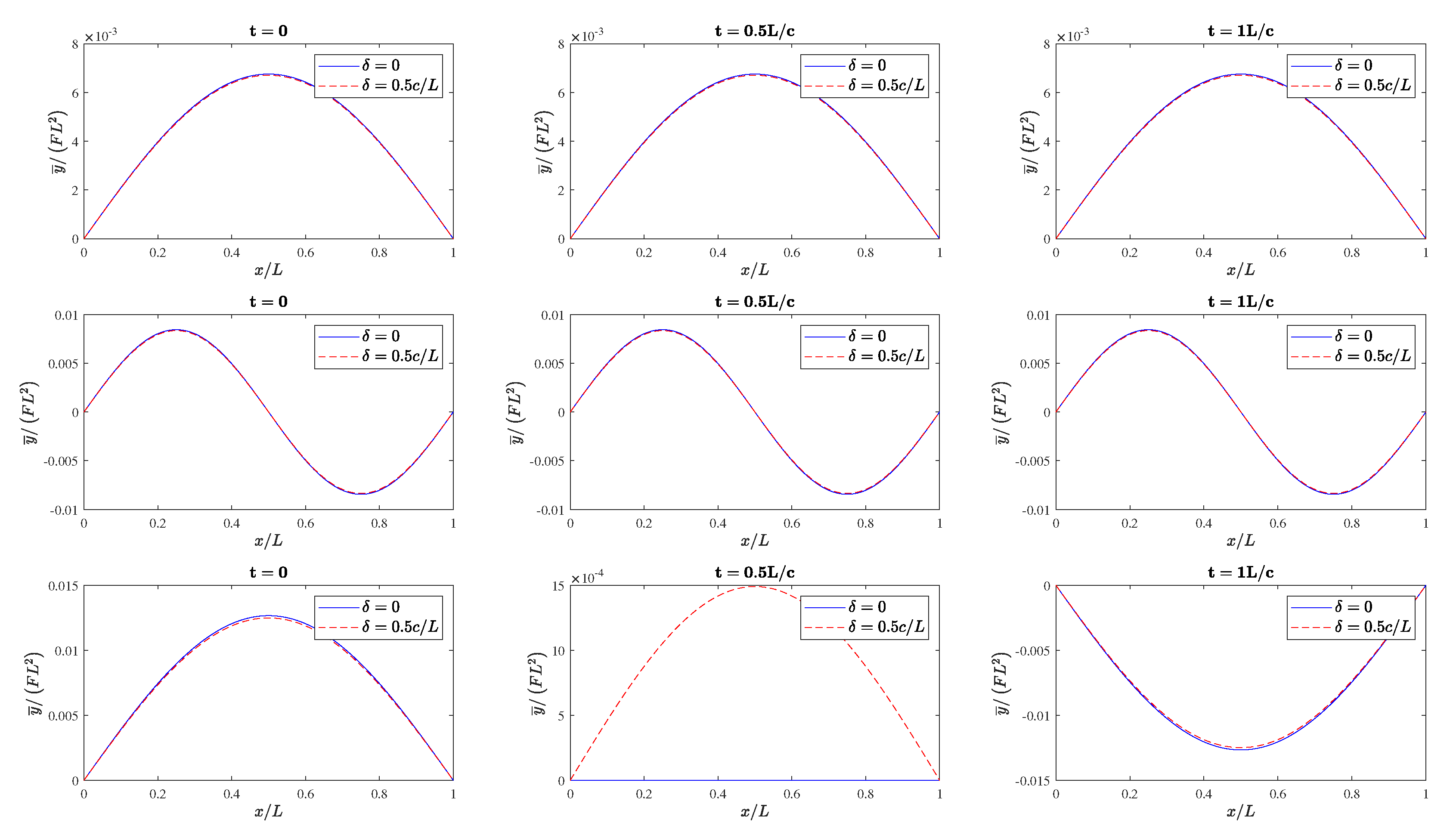
  110. Landau, L.D.; Lifshitz, E.M. Electrodynamics of Continuous Media, 2nd ed.; Course of Theoretical Physics; Butterworth-Heinemann: Oxford, UK, 1984; Volume 8. [Google Scholar]
  111. Campos, L.M.B.C. Complex Analysis with Applications to Flows and Fields, 1st ed.; Mathematics and Physics for Science and Technology; CRC Press: Boca Raton, FL, USA, 2011; Volume 1. [Google Scholar] [CrossRef]
  112. Campos, L.M.B.C. Simultaneous Differential Equations and Multi-Dimensional Vibrations, 1st ed.; Mathematics and Physics for Science and Technology; CRC Press: Boca Raton, FL, USA, 2019; Volume 4. [Google Scholar] [CrossRef]
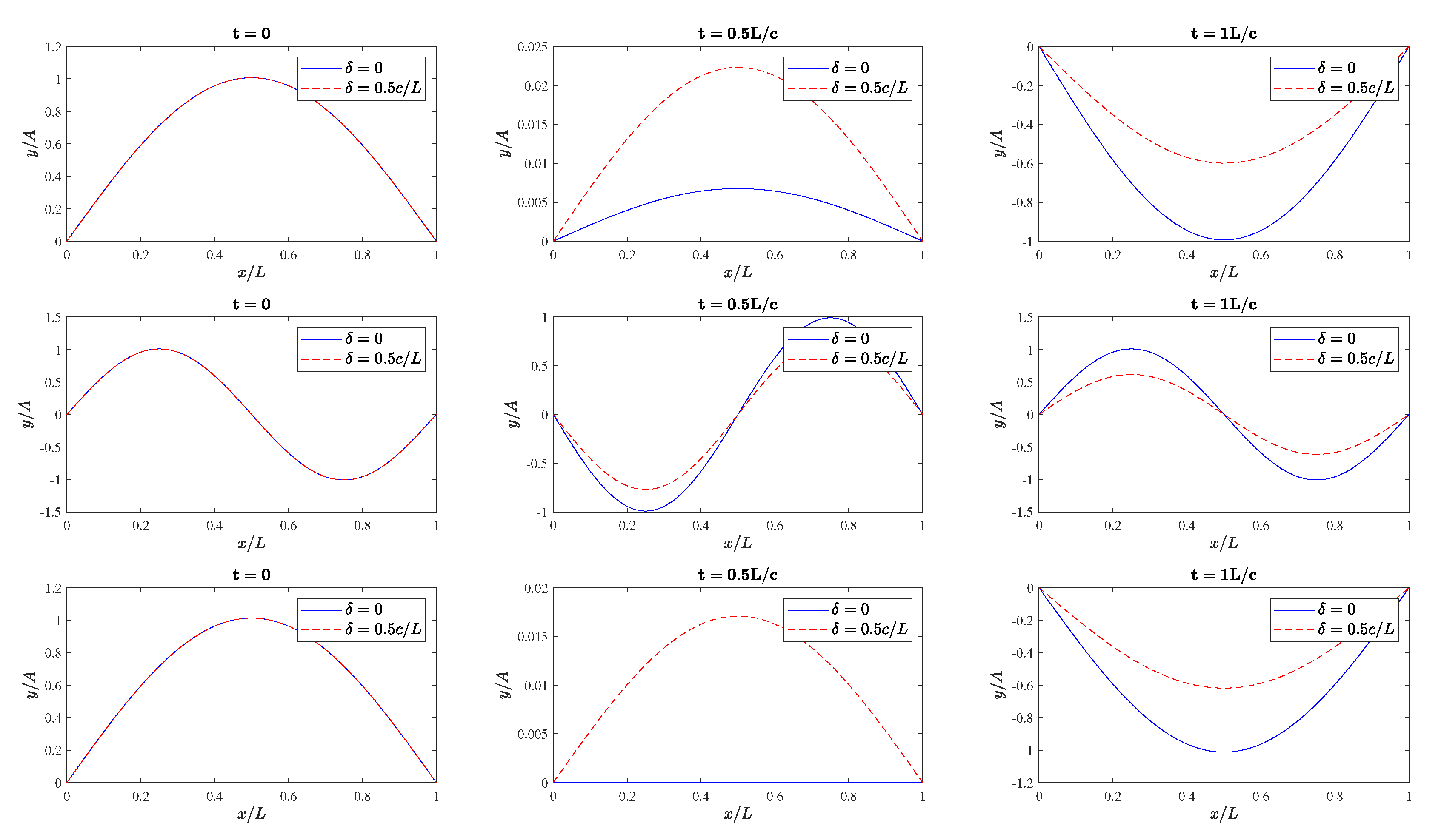
  113. Jackson, J.D. Classical Electrodynamics, 3rd ed.; John Wiley & Sons, Inc.: New York, NY, USA, 1999. [Google Scholar]
  114. Kuo, F.F. Network Analysis and Synthesis, 2nd ed.; John Wiley & Sons, Inc.: New York, NY, USA, 1966. [Google Scholar]
  115. Hayt, W.H., Jr.; Kemmerly, J.E.; Phillips, J.D.; Durbin, S.M. Engineering Circuit Analysis, 9th ed.; McGraw-Hill Education: New York, NY, USA, 2019. [Google Scholar]
  116. Campos, L.M.B.C. Linear Differential Equations and Oscillators, 1st ed.; Mathematics and Physics for Science and Technology; CRC Press: Boca Raton, FL, USA, 2019; Volume 4. [Google Scholar] [CrossRef]
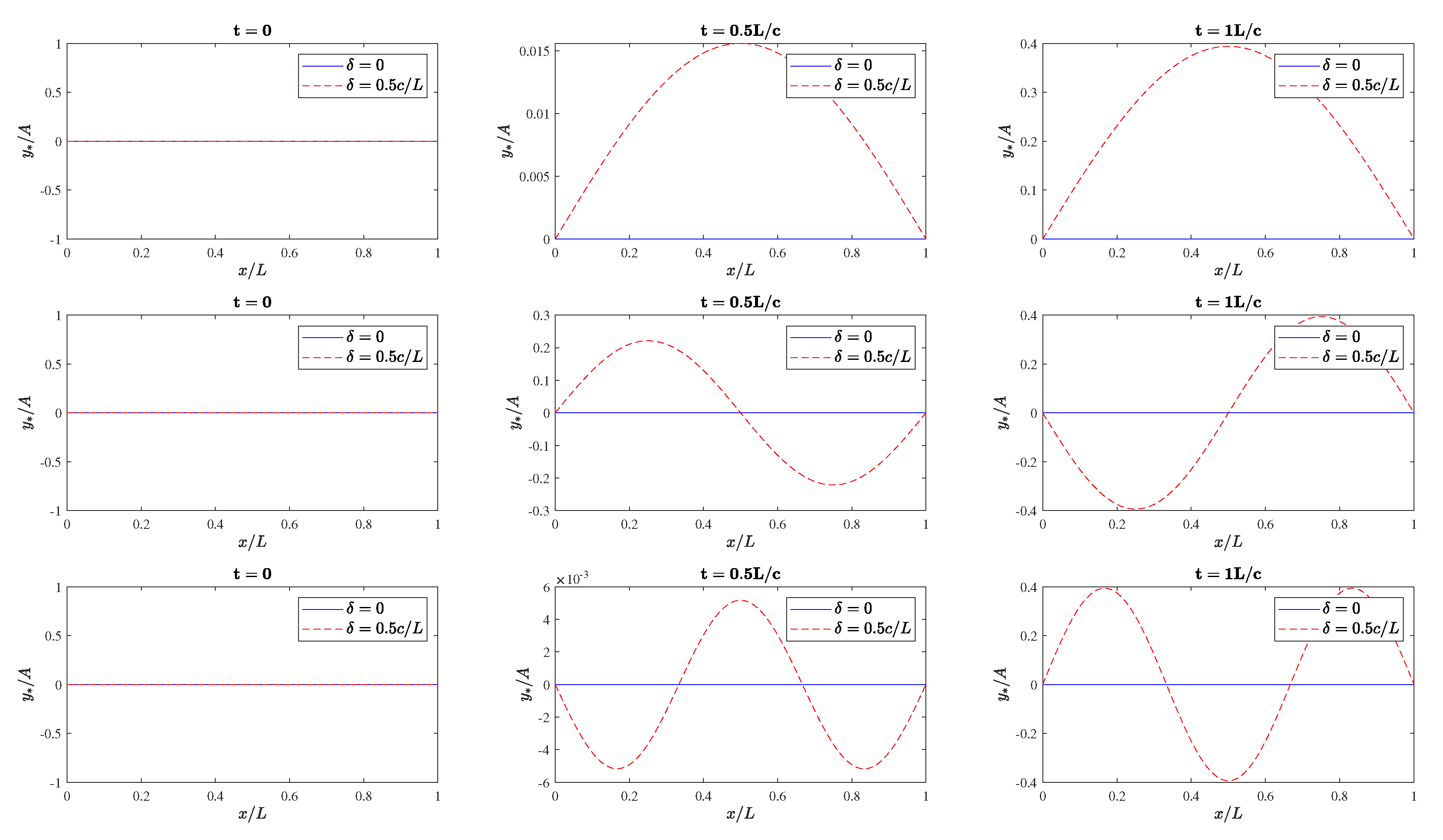
Figure 1. Free damped oscillations (for instance, of a string) at three distinct times. The blue solid lines are shown for no damping and the red dashed lines represent the oscillations with damping, δ = 0.5 c / L . Each row corresponds to a distinct set of values of the mode of free oscillation n and consequently on the value of wavenumber k n : the upper row is for n , k n = 1 , π / L , the middle row is for n , k n = 2 , 2 π / L , and the bottom row is for n , k n = 3 , 3 π / L . The plots are obtained for α n = 0 .
Applmech 04 00009 g001
Figure 2. Forced non-resonant oscillations at three distinct times. The blue solid lines correspond to no damping, δ = 0 , whereas the red dashed lines correspond to oscillations with damping, δ = 0.5 c / L . Each row corresponds to a distinct set of values of the mode of oscillation n (which influences the value of spatial wavenumber k) and ω ¯ : the upper row is for n , ω ¯ = 1 , 4 π c / L , the middle row is for n , ω ¯ = 2 , 4 π c / L , and the bottom row is for n , ω ¯ = 1 , 3 π c / L . In all the cases, the wavenumber is related to n by k n = n π / L . The plots are obtained for β = 0 .
Applmech 04 00009 g002
Figure 3. Total, free plus forced, non-resonant oscillations at three distinct times. The blue solid lines correspond to no damping, δ = 0 , whereas the red dashed lines correspond to oscillations with damping, δ = 0.5 c / L . Each row corresponds to a distinct set of values of the mode of oscillation n (which influences the value of spatial wavenumber k) and ω ¯ : the upper row is for n , ω ¯ = 1 , 4 π c / L , the middle row is for n , ω ¯ = 2 , 4 π c / L , and the bottom row is for n , ω ¯ = 1 , 3 π c / L . In all the cases, the wavenumber is related to n by k = n π / L . The plots are obtained for α = 0 = β . The plots are also obtained by setting A = F L 2 .
Applmech 04 00009 g003
Figure 4. Total free plus forced resonant oscillations with opposing amplitudes at three distinct times. The blue solid lines correspond to no damping, δ = 0 , whereas the red dashed lines correspond to oscillations with damping, δ = 0.5 c / L . In all the cases, the wavenumber is related to n by k = n π / L . Each row corresponds to a distinct set of values of the mode of free oscillation n and consequently on the value of wavenumber k n : the upper row is for n , k n = 1 , π / L , the middle row is for n , k n = 2 , 2 π / L and the bottom row is for n , k n = 3 , 3 π / L . The forced frequency is given by ω ¯ = k c . The plots are obtained for α = 0 and β = π / 2 α .
Applmech 04 00009 g004
Figure 5. Total non-resonant oscillations with forcing, canceling the initial free oscillation at time zero at three distinct times. The blue solid lines correspond to no damping, δ = 0 , whereas the red dashed lines correspond to oscillations with damping, δ = 0.5 c / L . Each row corresponds to a distinct set of values of the mode of oscillation n (which influences the values of spatial wavenumber k and free oscillation ω ˜ ) and ω ¯ : the upper row is for n , ω ¯ = 1 , 4 π c / L , the middle row is for n , ω ¯ = 2 , 4 π c / L , and the bottom row is for n , ω ¯ = 1 , 3 π c / L . In all the cases, the wavenumber is related to n by k = n π / L . The plots are obtained for α = 0 = β .
Applmech 04 00009 g005
Figure 6. Energy of total oscillation G divided by the energy of free oscillation G ˜ as a function of dimensionless time t c / L . The plots are shown as functions of k and δ L / c whereas in all cases k = n π / L .
Applmech 04 00009 g006
Figure 7. Forced resonant oscillations of a linear damped oscillator as a function of dimensionless time θ ω ˜ t where the applied frequency ω ¯ is equal to the oscillation frequency ω ˜ , that is, ω ¯ = ω ˜ . The plots are obtained for α = 0 . The forcing decays exponentially with time at the same rate as the free wave damping. The phases are matched to lead to oscillations that initially increase with time, ultimately decaying to damping, and even sooner for stronger damping.
Applmech 04 00009 g007
Figure 8. Total energy over all time of the total oscillation H , total energy over all time of the free oscillation H ˜ and the ratio J H / H ˜ , plotted as functions of the ratio of damping to oscillation frequency, q δ / ω ˜ .
Applmech 04 00009 g008
Figure 9. Ratio of the total to the free energy of oscillations as a function of the ratio of forcing decay ε to free damping δ showing a minimum at ψ = 1 in agreement with Table 2.
Applmech 04 00009 g009
Figure 10. Free oscillation for the first mode of oscillation leading to k = k 1 = π / L , with damping δ = 0.5 c / L , no phase shift, α = 0 , and at the middle of the string, x = L / 2 (dashed line); forced oscillation, also for the first mode of oscillation, k = k 1 = π / L , with opposing amplitude to the free oscillation, F = E A / c 2 , with applied phase shift, β = ϕ α , and with damping ε = 4 δ / 3 0.667 c / L , representing the case VI (dotted line); total oscillation as the sum of free and forced oscillations, in these conditions given by (133) (solid line). The three oscillations are represented as functions of dimensionless time t c / L .
Applmech 04 00009 g010
Table 1. Resonant forcing with exponential time decay. The results are obtained for α = 0 .
q θ m rad θ m t m / τ g θ m
0.051.9949114.30.31751.6456
0.101.9600112.30.31191.4906
0.151.925111.030.30641.3527
0.201.9650108.00.30001.2297
0.251.8535106.20.29501.1198
0.301.8169104.10.28921.0217
Table 2. Several values of the ratio ψ of forcing decay to free damping and the corresponding total energy of oscillation as a fraction R of the energy of the free oscillation, showing large reductions, which means strong vibration suppression.
FormulasValues
ψ 1 / 3 1 / 2 2 / 3 1 4 / 3 3 / 2 5 / 3 23
R ψ 1 1 / 3 1 / 10 0 1 / 28 1 / 15 1 / 10 1 / 6 1 / 3
1 0.330 0.100 0 0.036 0.067 0.100 0.167 0.333
Table 3. As the forcing decay comes closer to the damping, the reduction of total relative to free oscillation energy is more significant at the risk of coming too close to resonance, which could invalidate the result.
FormulasValues
ψ 4 / 3 5 / 4 6 / 5 7 / 6 8 / 7 9 / 8 10 / 9 11 / 10
R ψ 1 / 28 1 / 45 1 / 66 1 / 91 1 / 120 1 / 153 1 / 171 1 / 210
0.0357 0.0222 0.0152 0.0110 0.0083 0.0065 0.0058 0.0048
Table 4. Comparison of free and forced oscillations.
OscillationsFreeForced
AmplitudeA F = E A / c 2
Frequency ω ˜ = k 2 c 2 δ 2 ω ¯
Phase α β
Exponential decay in time δ = c 2 / 2 χ ε
Table 5. Six cases to counter free oscillations (I–II: undamped; III–VI: with damping) and forcing with constant (III–IV) or decaying (V–VI) amplitude. Both non-resonant (I, III, VI) and resonant (II, IV, V) cases are considered.
NumberCaseMain PhenomenonEnergy
INon-resonant forcingDistinct frequency adds energyIncreases
IIResonant forcingApplied frequency equal to natural frequencyUp to 75% reduction in first period
IIINon-resonant without decayForcing with constant amplitude dominatesSmall reduction in first period
IVResonant without decayForcing with constant amplitude dominatesSmall reduction over fraction of first period
VResonant with decayDamping slow to dominate resonant growthReduction only for strong damping
VINon-resonant with decayDecay of total oscillationReduction up to over 96% in energy over all time
Disclaimer/Publisher’s Note: The statements, opinions and data contained in all publications are solely those of the individual author(s) and contributor(s) and not of MDPI and/or the editor(s). MDPI and/or the editor(s) disclaim responsibility for any injury to people or property resulting from any ideas, methods, instructions or products referred to in the content.