Structural Analysis of a Composite Passenger Seat for the Case of an Aircraft Emergency Landing


Abstract
:1. Introduction
2. Materials and Methods
3. Results
4. Weight Reduction
5. Discussion
Author Contributions
Funding
Institutional Review Board Statement
Informed Consent Statement
Data Availability Statement
Conflicts of Interest
References
- Guida, M.; Marulo, F.; Caprio, F.; Russo, S. Occupants’ Injury during a Drop Test of an Advanced Composite Fuselage Section. Aerotec. Missili Spaz. 2018, 97, 129–134. [Google Scholar] [CrossRef]
- Olschinka, C.; Schumacher, A. Dynamic Simulation of Flight Passenger Seats. In Proceedings of the 5th LS-DYNA Conference, Ulm, Germany, 12–13 October 2006. [Google Scholar]
- Meola, C.; Boccardi, S.; Carlomango, G.M. Composite Materials in the Aeronautical Industry. In Infrared Thermography in the Evaluation of Aerospace Composite Materials; Elsevier Science: Amsterdam, The Netherlands, 2017; pp. 1–24. [Google Scholar]
- Yi, X.S. Development of Multifunctional Composites for Aerospace Application. In Multifunctionality of Polymer Composites; William Andrew: Norwich, NY, USA, 2015; pp. 367–418. [Google Scholar]
- Kassapoglou, C. Design and Analysis of Composite Structures with Applications to Aerospace Structures; Wiley: Hoboken, NJ, USA, 2013; ISBN 9781118401606. [Google Scholar]
- Campbell, F.C. Structural Composite Materials; ASM International: Almere, The Netherlands, 2010. [Google Scholar]
- David Müzel, S.; Bonhin, E.P.; Guimarães, N.M.; Guidi, E.S. Application of the Finite Element Method in the Analysis of Composite Materials: A Review. Polymers 2020, 12, 818. [Google Scholar] [CrossRef] [PubMed] [Green Version]
- Dandekar, C.R.; Shin, Y.C. Modeling of machining of composite materials: A review. Int. J. Mach. Tools Manuf. 2012, 57, 102–121. [Google Scholar] [CrossRef]
- Cook, R.D. Finite Element Modeling for Stress Analysis, 1st ed.; John Wiley & Sons, Inc.: Hoboken, NJ, USA, 1995. [Google Scholar]
- Tenek, L.T.; Argyris, J. Finite Element Analysis for Composite Structures. In Solid Mechanics and Its Applications; Gladwell, G.M., Ed.; Springer: Dordrecht, The Netherlands, 1998; Volume 59. [Google Scholar]
- Zhao, L.G.; Warrior, N.A.; Long, A.C. Finite element modelling of damage progression in non-crimp fabric reinforced composites. Compos. Sci. Technol. 2006, 66, 36–50. [Google Scholar] [CrossRef]
- Mkaddem, A.; Demirci, I.; Mansori, M.E. A micro–macro combined approach using FEM for modelling of machining of FRP composites: Cutting forces analysis. Compos. Sci. Technol. 2008, 68, 3123–3127. [Google Scholar] [CrossRef]
- Zhao, S.Y.; Xue, P. New Two-Dimensional Polynomial Failure Criteria for Composite Materials. Adv. Mater. Sci. Eng. 2014, 2014, 503483. [Google Scholar] [CrossRef] [Green Version]
- Paris, F. A Study of Failure Criteria of Fibrous Composite Materials; NASA/CR-2001-210661; NASA: Hampton, UK, 2001.
- Camanho, P.P.; Dávila, C.G. Mixed-Mode Decohesion Finite Elements for the Simulation of Delamination in Composite Materials; NASA/TM-2002-211737; NASA: Hampton, UK, 2002.
- Madenci, E. Free vibration and static analyses of metal-ceramic FG beams via high-order variational MFEM. Steel Compos. Struct. 2021, 39, 493–509. [Google Scholar] [CrossRef]
- Bhonge, P. A Methodology for Aircraft Seat Certification by Dynamic Finite Element Analysis; Wichita State University: Wichita, KS, USA, 2008. [Google Scholar]
- U.S.Department of Transportation. Federal Aviation Administration. Available online: https://www.faa.gov/ (accessed on 22 June 2022).
- Dhole, N.E. Development and Validation of a Finite Element Model of a Transport Aircraft Seat Under Part 25.562 Dynamic Test Conditions; Wichita State University: Wichita, KS, USA, 2010. [Google Scholar]
- Lamanna, G.; Vanacore, A.; Guida, M.; Caputo, F.; Marulo, F.; Vitolo, B.; Cicatiello, S. Development of a Head Injury Criteria-Compliant Aircraft Seat by Design of Experiments. Aerospace 2019, 6, 95. [Google Scholar] [CrossRef] [Green Version]
- DeWeese, R.; Moorcroft, D.; Philippens, M.M.G.M. Assessment of Head and Neck Injury Potential During Aircraft Longitudinal Impacts; Office of Aerospace Medicine: Washington, DC, USA, 2016.
- Chen, E. Aircraft Seat Row-to-row Head Injury Criteria (HIC) Simulation Using LS-DYNA. In Proceedings of the 15th International LS-DYNA Users Conference, Dearborn, MI, USA, 10–12 June 2018. [Google Scholar]
- Quigley, C.; Southall, D.; Freer, M.; Moody, A.; Porter, J.M. Anthropometric Study to Update Minimum Aircraft Seating Standards; Loughborough University: Loughborough, UK, 2001. [Google Scholar]
- Hallquist, J. LS-DYNA Theory Manual; Livermore Software Technology Corporation: Livermore, CA, USA, 2006. [Google Scholar]
- Camanho, P.; Matthews, F. Stress analysis and strength prediction of mechanically fastened joints in FRP: A review. Compos. Part A Appl. Sci. Manuf. 1997, 28, 529–547, ISSN 1359-835X. [Google Scholar] [CrossRef] [Green Version]
- Guha, S.; Bhalsod, D.; Krebs, J. LSTC Hybrid III 50th Fast Dummy Positioning & Post-Processing; Livermore Software Technology Corporation: Troy, MI, USA, 2011. [Google Scholar]
- Lin, M.P.; Chang, C.M.; Tsai, C.H.; Tai, C.H.; Lee, C.-T. Usage of LSTC_NCAC Hybrid III 50th Dummy in Frontal Ocupant Simulation. In Proceedings of the 13th International LS-DYNA Users Conference, New Taipei City, Taiwan, 5–7 October 2021. [Google Scholar]
- Administration, F.A. Methodology for Dynamic Seat Certification by Analysis for Use in Parts 23, 25, 27, and 29 Airplanes and Rotorcraft; Office of the Federal Register, National Archives and Records Administration: Washington, DC, USA, 2003.
- Dhole, N.; Yadav, V.; Olivares, G. Certification by Analysis of a Typical Aircraft Seat. In Proceedings of the 12th International LS-DYNA Users Conference, Dearborn, MI, USA, 3–5 June 2012. [Google Scholar]
- Erden, S.; Yayla, P. Finite Element Stress Analysis of Airplane Seat. Eur. Mech. Sci. 2021, 5, 6–13. [Google Scholar] [CrossRef]
- Xiang, G.; Pownuk, A.; Kosheleva, O.; Starks, S.A. Von Mises Failure Criterion in Mechanics of Materials: How to Efficiently Use it Under Interval and Fuzzy Uncertainty. In Proceedings of the NAFIPS 2007—2007 Annual Meeting of the North American Fuzzy Information Processing Society, San Diego, CA, USA, 24–27 June 2007. [Google Scholar]
- Feraboli, P.; Wade, B. Crushing Behavior of Laminated Composite Structural Elements: Experiment and LS-DYNA Simulation; DOT/FAA/TC-15/25; U.S. Department of Transportation Federal Aviation Administration Office of Aviation Research: Washington, DC, USA, 2016.
- Feraboli, P.; Wade, B. Simulation Laminated Composite Materials Using LS-DYNA Material Model MAT54: Single-Element Investigation; Federal Aviation Administration: Egg Harbor Township, NJ, USA, 2015.
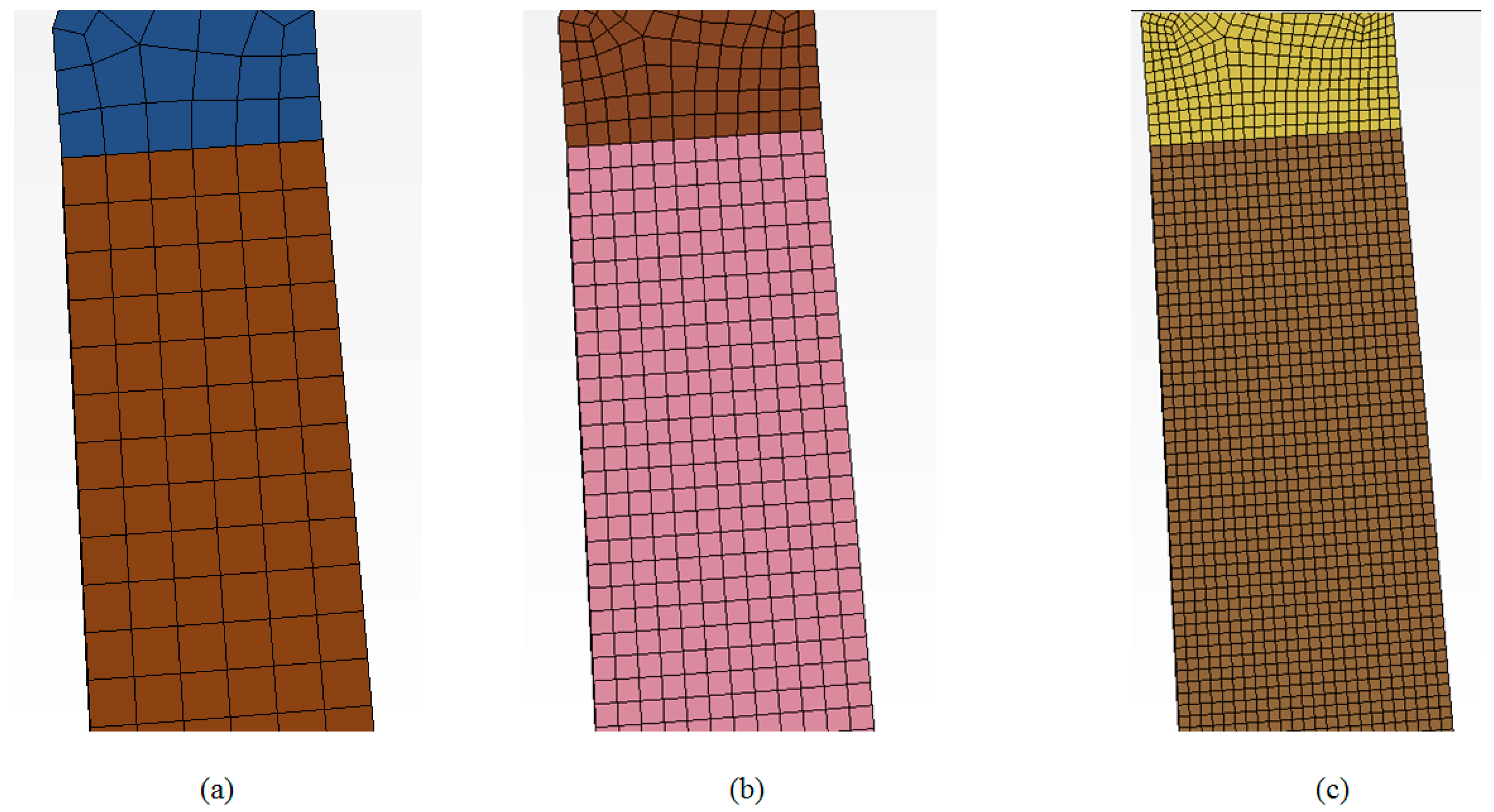
- Bjorkman, G.; Molitoris, D. Mesh Convergence Studies for Thin Shell Elements Developed by the ASME Task Group on Computational Modeling. In Proceedings of the ASME 2011 Pressure Vessels and Piping Conference, American Society of Mechanical Engineers, Baltimore, MD, USA, 17–21 July 2011. [Google Scholar]
- LSTC. LS-Dyna Keyword User’s Manual Volume I; Livermore Software Technology Corporation: Livermore, CA, USA, 2015. [Google Scholar]
- LSTC. LS-Dyna Keyword User’s Manual Volume II Material Models; Livermore Software Technology Corporation: Livermore, CA, USA, 2015. [Google Scholar]


| Test 1 | Test 2 |
|---|---|
 |  |
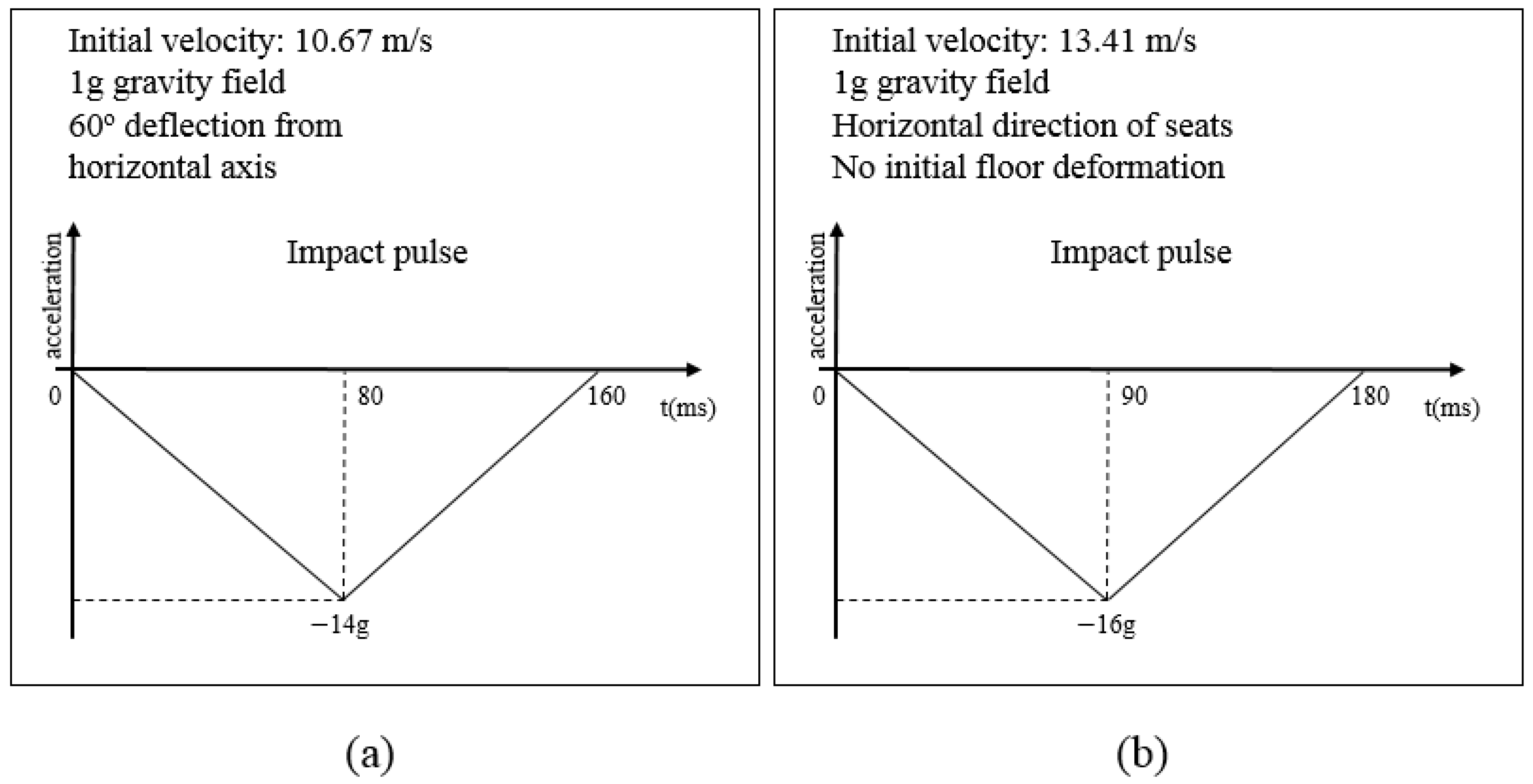
| Vertical loading | Horizontal loading |
| Seat rotation: 60° | 10° pitch, 10° yaw, 10° roll |
| Initial velocity: 10.67 m/s | Initial velocity: 13.41 m/s |
| Maximum deceleration: 14 g at 80 ms | Maximum deceleration: 16 g at 90 ms |
| Injury criteria: Spinal loading | Injury criteria: HIC, Femur loading |
| Test 3 |
|---|
 |
| Horizontal loading |
| 10° pitch, 10° yaw, 10° roll |
| Initial velocity: 13.41 m/s |
| Maximum deceleration: 16 g at 90 ms |
| Injury criteria: HIC, Femur loading |
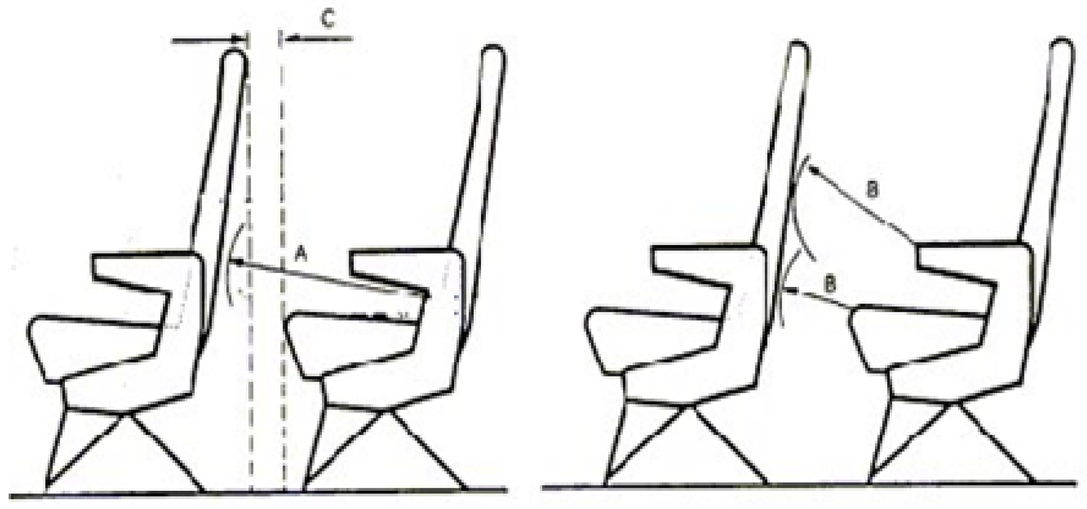
| Dimension | Description | Minimum |
|---|---|---|
| A | The minimum distance between the back support cushion of a seat and the back of the seat or another fixed structure in the front | 26 inches (660 mm) |
| B | The minimum distance between a seat and the seat or another fixed structure in the front | 7 inches (178 mm) |
| C | The minimum vertically projected distance between seat rows or between a seat and any fixed structure in front of the seat | 3 inches (76 mm) |
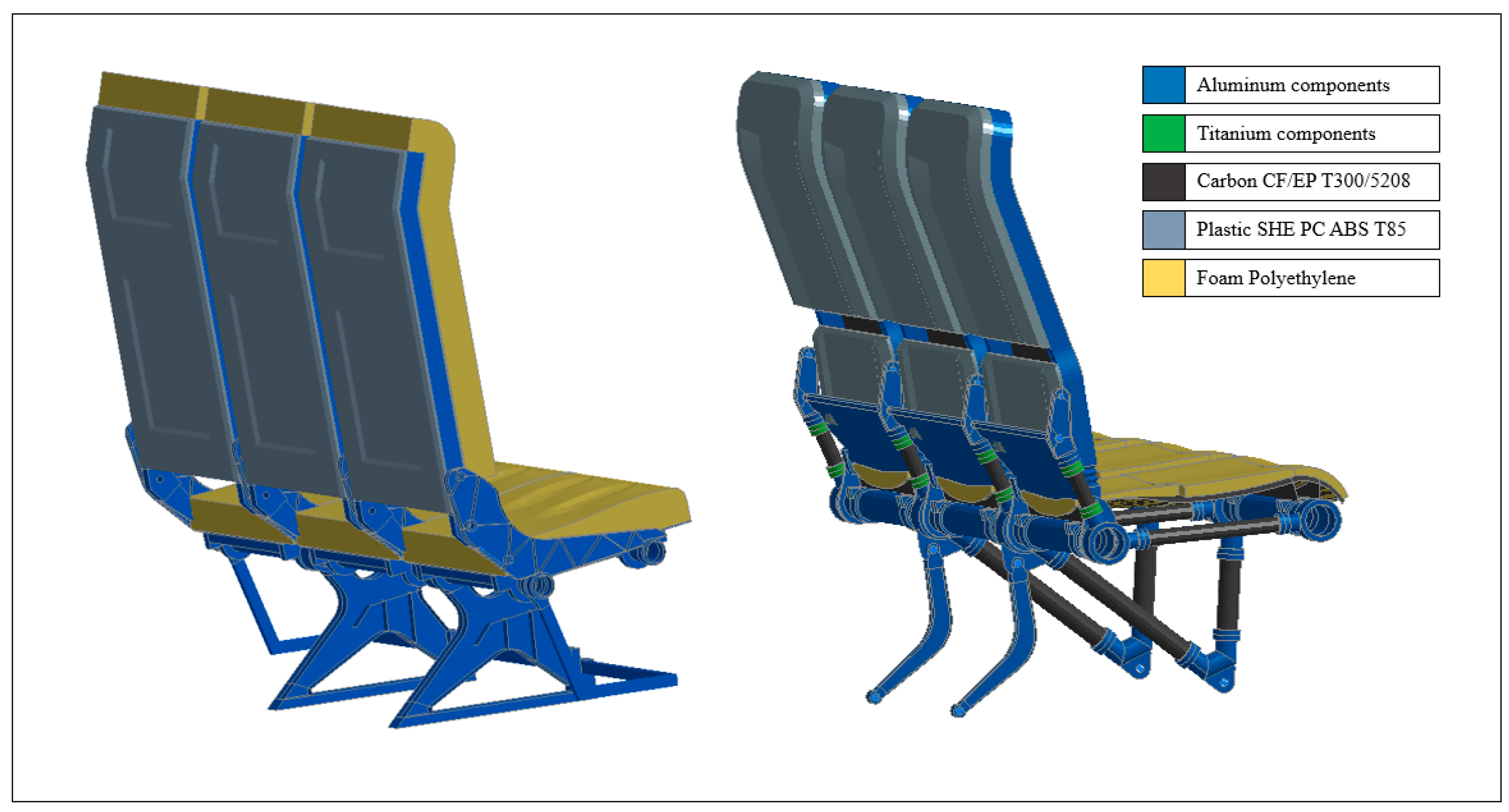
| Material | Density | Young Modulus | Ultimate Strength (σSU) | Yield Strength (σSF) | Poisson’s Ratio | Elongation at Break |
|---|---|---|---|---|---|---|
| Aluminum 2024-T3 | 2780 kg/m3 | 73.1 GPa | 483 MPa | 345 MPa | 0.33 | 18% |
| Aluminum 6082-T6 | 2700 kg/m3 | 70.0 GPa | 300 MPa | 255 MPa | 0.33 | 10% |
| Aluminum 7075-T6 | 2810 kg/m3 | 71.7 GPa | 572 MPa | 502 MPa | 0.33 | 11% |
| Titanium 3AL-2.5V | 4480 kg/m3 | 107 GPa | 790 MPa | 690 MPa | 0.33 | 15% |
| PC ABS T85 | 1115 kg/m3 | 2.3 GPa | 54 MPa | 50 MPa | 0.35 | 80% |
| Material | Density | Compressive Deflection |
|---|---|---|
| Polyethylene foam ETHAFOAM 4191FR | 35.2 kg/m3 | 10% 0.055 MPa |
| 25% 0.069 MPa | ||
| 50% 0.138 MPa |
| Property | Value |
|---|---|
| Ply thickness, t | 0.125 mm |
| Modulus of elasticity 0°, E1 | 181 GPa |
| Modulus of elasticity 90°, E2 | 10.3 GPa |
| Poisson’s ratio, v12 | 0.28 |
| Shear Modulus, G12 | 7.17 GPa |
| Tensile strength 0°, Xt | 1500 MPa |
| Compressive strength 0°, Xc | 1500 MPa |
| Tensile strength 90°, Yt | 40 MPa |
| Compressive strength 90°, Yc | 246 MPa |
| Shear strength, Sc | 68 MPa |
| Density, ρ | 1760 kg/m3 |
| Element Type | Element Formulation |
|---|---|
| Shell elements | Formulation (2) Belytscho–Tsay |
| Solid elements | Formulation (1) Constant stress solid element & Formulation (2) Fully integrated S/R solid |
| Beam elements | Formulation (1) Hughes–Liu with cross-section integration |
| 1D seatbelt elements | Seatbelt formulation |
| 2D seatbelt elements | Formulation (9) Fully integrated Belytscho–Tsay membrane |
| Mass | Length | Time | Force | Stress | Energy | Gravity |
|---|---|---|---|---|---|---|
| kg | mm | ms | kN | GPa | ΚN-mm | 9.806 × 10⁻³ |
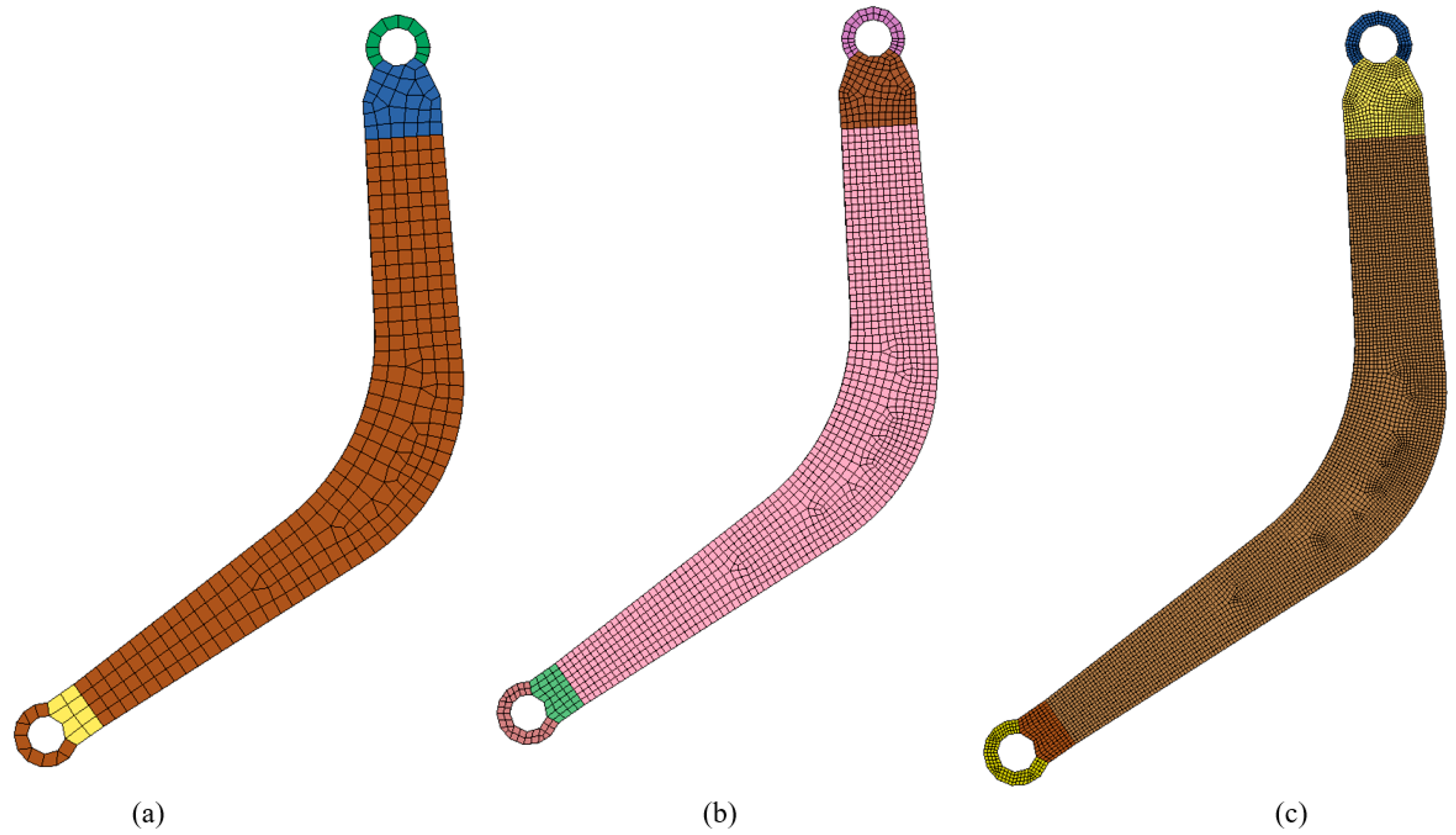
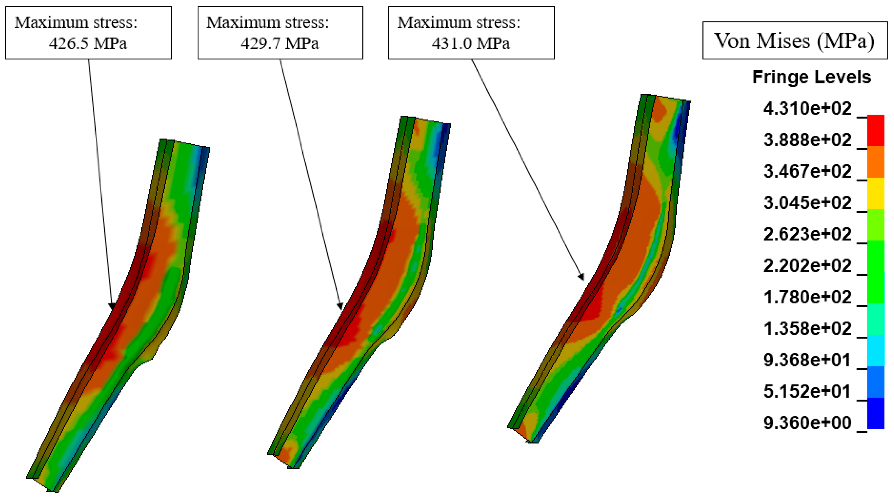
| Element Number | Maximum Stress, Von Mises | Computational Time | Hardware |
|---|---|---|---|
| 692 elements | 426.5 MPa | 35 s | DDR4 24 GB RAMIntel core i7-6700K, 4.00 GHz |
| 2768 elements | 429.7 MPa | 144 s | |
| 11,052 elements | 431.0 MPa | 550 s |
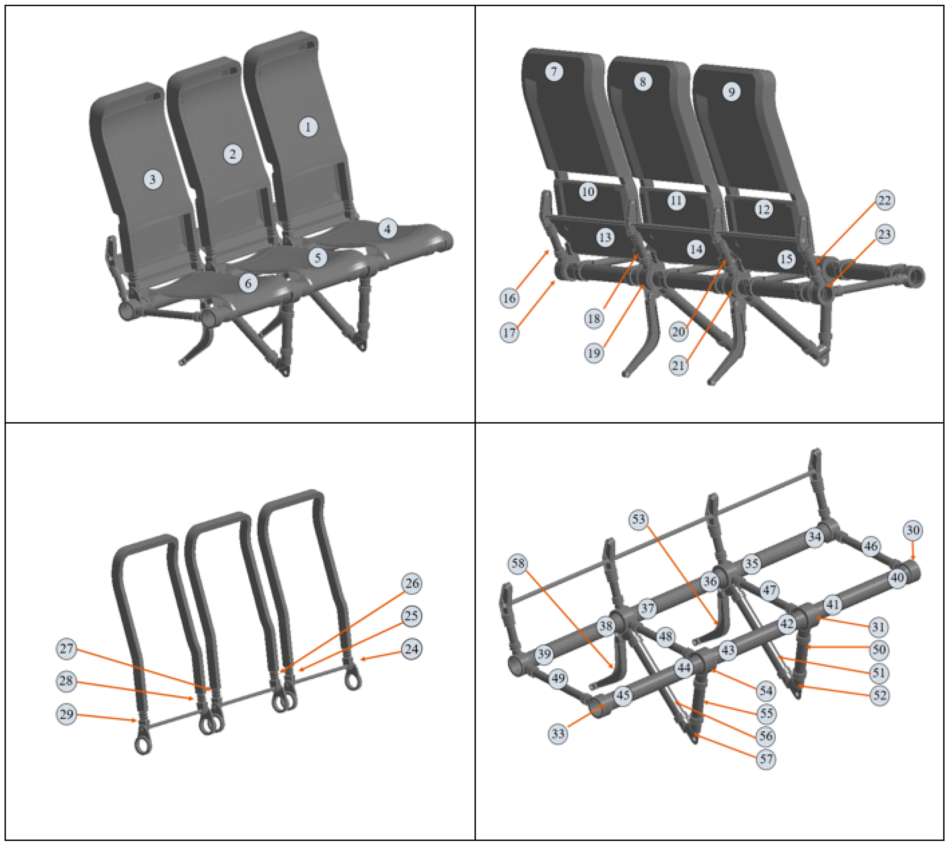
| Seat Component Location | Material | Frontal Seat Row Safety Factor | Rear Seat Row Safety Factor |
|---|---|---|---|
| 7 | PC ABS T85 | 1.10 | 5.56 |
| 8 | PC ABS T85 | 1.12 | 7.66 |
| 9 | PC ABS T85 | 1.07 | 5.04 |
| 10 | PC ABS T85 | 1.12 | 2.82 |
| 11 | PC ABS T85 | 1.12 | 1.95 |
| 12 | PC ABS T85 | 1.17 | 4.35 |
| 13 | Aluminum 6082-T6 | 1.63 | 1.80 |
| 14 | Aluminum 6082-T6 | 1.57 | 2.38 |
| 15 | Aluminum 6082-T6 | 1.22 | 1.22 |
| 17 | Titanium 3AL-2.5V | 3.51 | 11.62 |
| 19 | Titanium 3AL-2.5V | 3.24 | 13.39 |
| 21 | Titanium 3AL-2.5V | 3.97 | 13.28 |
| 23 | Titanium 3AL-2.5V | 3.50 | 13.37 |
| 24 | Aluminum 2024-T3 | 1.41 | 4.47 |
| 25 | Aluminum 2024-T3 | 1.40 | 3.83 |
| 26 | Aluminum 2024-T3 | 1.40 | 4.95 |
| 27 | Aluminum 2024-T3 | 1.40 | 4.47 |
| 28 | Aluminum 2024-T3 | 1.39 | 3.72 |
| 29 | Aluminum 2024-T3 | 1.41 | 4.09 |
| 30 | Aluminum 7075-T6 | 2.60 | 2.05 |
| 31 | Aluminum 7075-T6 | 2.50 | 1.40 |
| 32 | Aluminum 7075-T6 | 2.49 | 2.04 |
| 33 | Aluminum 7075-T6 | 2.32 | 2.25 |
| 34 | Aluminum 2024-T3 | 1.50 | 3.80 |
| 35 | Aluminum 2024-T3 | 1.67 | 5.60 |
| 36 | Aluminum 2024-T3 | 1.73 | 5.08 |
| 37 | Aluminum 2024-T3 | 1.64 | 5.55 |
| 38 | Aluminum 2024-T3 | 1.68 | 4.31 |
| 39 | Aluminum 2024-T3 | 1.50 | 3.83 |
| 40 | Aluminum 2024-T3 | 2.68 | 3.80 |
| 41 | Aluminum 2024-T3 | 1.37 | 1.45 |
| 42 | Aluminum 2024-T3 | 1.53 | 1.52 |
| 43 | Aluminum 2024-T3 | 1.45 | 1.57 |
| 44 | Aluminum 2024-T3 | 1.37 | 1.47 |
| 45 | Aluminum 2024-T3 | 2.30 | 4.03 |
| 52 | Aluminum 2024-T3 | 1.40 | 1.80 |
| 53 | Aluminum 2024-T3 | 1.13 | 1.37 |
| 56 | Aluminum 2024-T3 | 1.42 | 1.67 |
| 57 | Aluminum 2024-T3 | 1.12 | 1.38 |
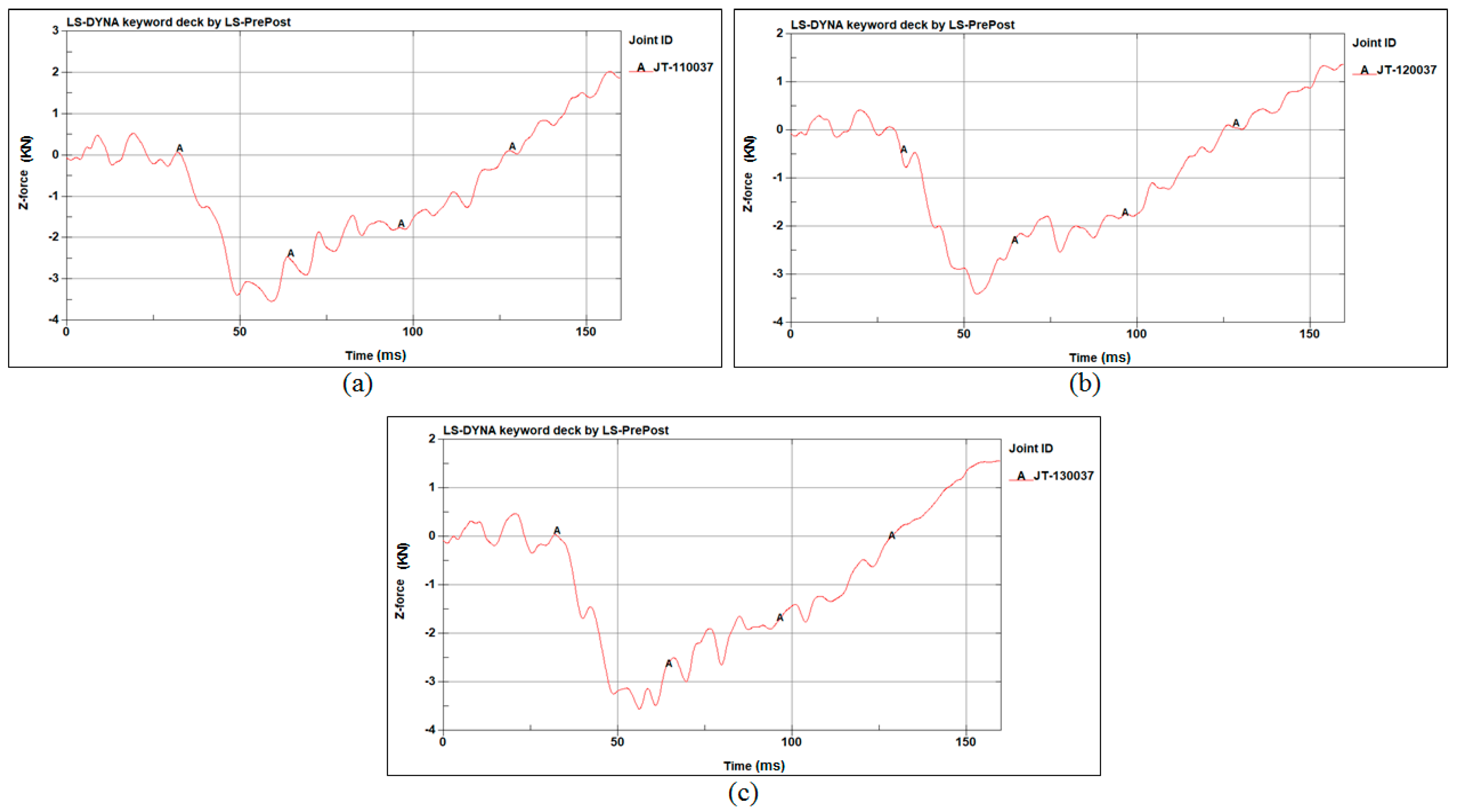
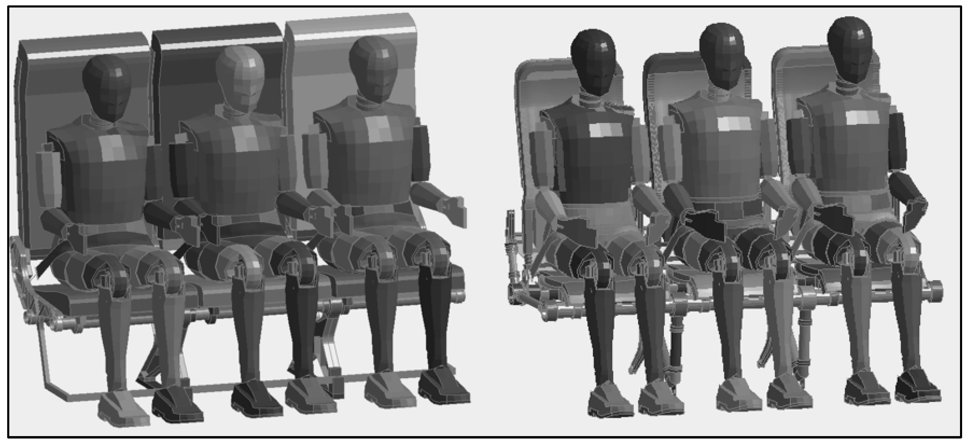
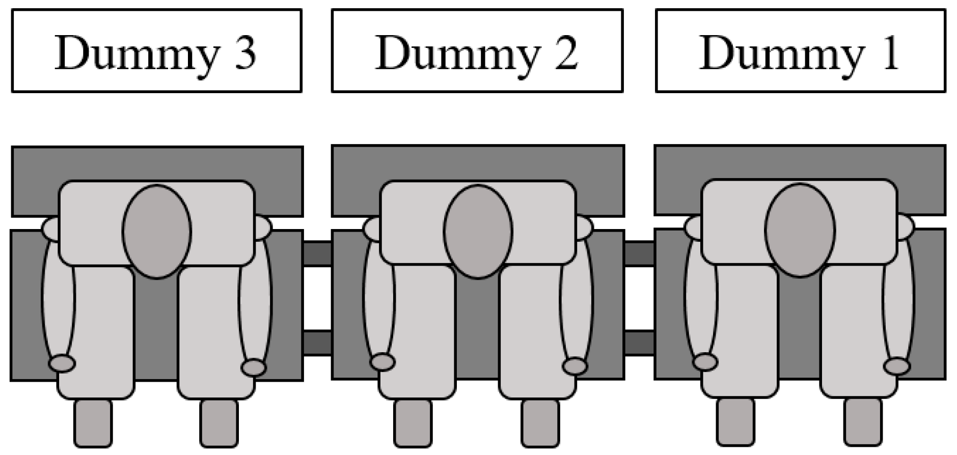
| Dummy Position | Lumbar Compressive Load | Critical Value |
|---|---|---|
| 1 | −3.53 KN | −6.67 KN |
| 2 | −3.40 KN | −6.67 KN |
| 3 | −3.54 KN | −6.67 KN |
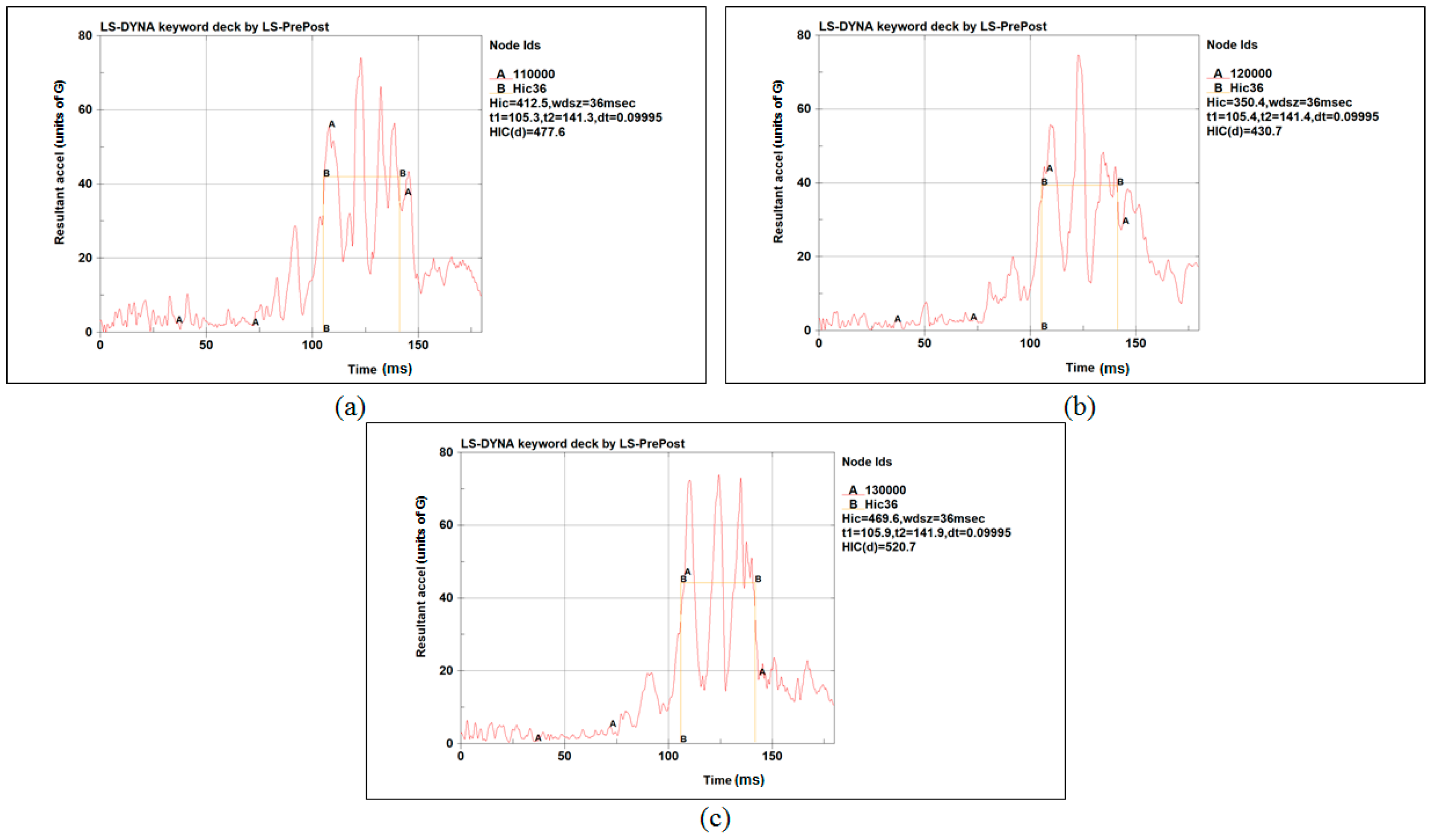
| Dummy Position | HIC | Critical Value |
|---|---|---|
| 1 | 477.6 units | 1000 units |
| 2 | 430.7 units | 1000 units |
| 3 | 520.7 units | 1000 units |
| Dummy Position | Left Femur Compressive Load | Right Femur Compressive Load | Critical Value |
|---|---|---|---|
| 1 | −2.19 KN | −2.12 KN | −10.012 KN |
| 2 | −1.99 KN | −3.15 KN | −10.012 KN |
| 3 | −2.06 KN | −4.51 KN | −10.012 KN |
| Structural Component | Model 1 Weight (kg) | Model 2 Weight (kg) | Weight Reduction |
|---|---|---|---|
| Back rests | 15 | 8.42 | 43.8% |
| Seat pans | 13.6 | 6.93 | 49.0% |
| Spreaders | 4.73 | 4.45 | 5.9% |
| Tubular axis | 6 | 2.62 | 56.3% |
| Seat legs | 12.67 | 4.61 | 63.6% |
| Total | 52 | 27.02 | 48% |
Disclaimer/Publisher’s Note: The statements, opinions and data contained in all publications are solely those of the individual author(s) and contributor(s) and not of MDPI and/or the editor(s). MDPI and/or the editor(s) disclaim responsibility for any injury to people or property resulting from any ideas, methods, instructions or products referred to in the content. |
© 2022 by the authors. Licensee MDPI, Basel, Switzerland. This article is an open access article distributed under the terms and conditions of the Creative Commons Attribution (CC BY) license (https://creativecommons.org/licenses/by/4.0/).
Share and Cite
Tzanakis, G.; Kotzakolios, A.; Giannaros, E.; Kostopoulos, V. Structural Analysis of a Composite Passenger Seat for the Case of an Aircraft Emergency Landing. Appl. Mech. 2023, 4, 1-19. https://doi.org/10.3390/applmech4010001
Tzanakis G, Kotzakolios A, Giannaros E, Kostopoulos V. Structural Analysis of a Composite Passenger Seat for the Case of an Aircraft Emergency Landing. Applied Mechanics. 2023; 4(1):1-19. https://doi.org/10.3390/applmech4010001
Chicago/Turabian StyleTzanakis, Georgios, Athanasios Kotzakolios, Efthimis Giannaros, and Vassilis Kostopoulos. 2023. "Structural Analysis of a Composite Passenger Seat for the Case of an Aircraft Emergency Landing" Applied Mechanics 4, no. 1: 1-19. https://doi.org/10.3390/applmech4010001
APA StyleTzanakis, G., Kotzakolios, A., Giannaros, E., & Kostopoulos, V. (2023). Structural Analysis of a Composite Passenger Seat for the Case of an Aircraft Emergency Landing. Applied Mechanics, 4(1), 1-19. https://doi.org/10.3390/applmech4010001