Article

A New Coupled Approach for Enthalpy Pumping Consideration in a Free Piston Stirling Engine (FPSE)

1
Université de Lorraine, CNRS, LEMTA, F-54000 Nancy, France
2
IMT Atlantique, GEPEA, UMR CNRS 6144, F-44307 Nantes, France
*
Author to whom correspondence should be addressed.
Appl. Mech. 2022, 3(2), 339-359; https://doi.org/10.3390/applmech3020021
Submission received: 23 February 2022 / Revised: 21 March 2022 / Accepted: 23 March 2022 / Published: 25 March 2022
(This article belongs to the Special Issue Applied Thermodynamics: Modern Developments)

Abstract

:
One group of losses that can considerably affect the performance of Free Piston Stirling Engines’ (FPSE) is the enthalpy pumping and the shuttle effect, which are due to the gap standing between the cylinder and the displacer. The shuttle effect is induced by the periodic displacer motion between the hot and the cold sources. The enthalpy pumping, which is the subject of the present study, is due to the short-circuit-like flow between the hot and cold spaces. To study these losses, first, a fine nonlinear dynamic model of the FPSE is developed and validated. Then, to study the enthalpy pumping based on that, a coupled model (for the first time) and a decoupled model are presented. The difference between the two models is that the first one provides a dynamic and a thermic linkage between the Stirling and loss model, while the second one studies them separately. The effect of the gap size on both loss models was investigated. The coupled and decoupled modeling results were quite different due to the considerable effect of the enthalpy pumping on the FPSE response. The results showed that the enthalpy pumping in the decoupled model exceeds the total output power when the gap exceeds 30   μ m , and when the gap exceeds 70   μ m , the enthalpy pumping is around ten times larger than the output power. In contrast, the enthalpy pumping in the coupled model is always less than the output power, which is logical. Thus, the coupled one was presented as the adapted model that should be considered for further FPSE studies.

1. Introduction

One of the most important parameters in heat-work conversion machines is their internal energy losses. These losses have a significant impact on the machine’s performance and decrease its efficiency. Thus, taking these losses into account when modeling heat-work conversion machines is very important to have accurate results. A Stirling engine is one of these machines for which internal energy losses play a vital role. Based on the transmission mechanism point of view and other parameters, these engines can be categorized into different types [1,2]. The focus of the present study is on the Free Piston Stirling Engine (FPSE) that was invented by W.T. Beale in 1964. Displacer gap losses have been underestimated in the Stirling engines in the past [3]. These losses can be divided into two categories: enthalpy pumping and shuttle effect [3,4]. The first is significant, especially for FPSEs, because, due to stability and starting issues, these systems usually use relatively higher clearances around pistons [5,6]. This clearance causes gas leakage between expansion and compression spaces, which results in the so-called enthalpy pumping [7,8]. Moreover, each time that the displacer moves from one side to another side, it absorbs some heat from the hot side and rejects it to the cold side. This last effect is called the shuttle heat transfer or loss [7,8]. Since the enthalpy pumping directly affects the pressure variation and energy balance of the expansion and compression spaces due to the gas leakage between them, the focus of the present study is on the enthalpy pumping in the FPSE.

1.1. Literature Review

Despite the importance of the losses on the Stirling engines, there are just a few numbers of studies that focused on these losses in the Stirling engines and analyzed them. Rios [9] provided an approximate solution for shuttle heat transfer losses of a reciprocating machine by linearization and use of the Fourier series. He has not provided a model of the engine. Berchowitz [10] also, by assuming sinusoidal movement for the displacer of a Stirling engine, calculated the enthalpy pumping and the shuttle heat transfer losses. Baik and Chang [11], by assuming a known sinusoidal movement for a Stirling engine displacer, calculated the shuttle heat transfer. They did not take into account the gas compressibility nor the pressure gradient in the gap. They also neglected the effect of the gas flow between the cylinder and the displacer and only considered the heat conduction in the displacer and the cylinder bodies. Chang et al. [12], using the same assumption as Baik and Chang [11], and considering the effect of the gap flow, calculated the shuttle heat transfer. Kotsubo and Swift [13] used the thermoacoustic theory to calculate the enthalpy pumping and shuttle heat transfer losses. They considered the leakage flow rate as a known parameter. Mabrouk et al. [7,8] studied the enthalpy pumping and shuttle effect in Stirling engines. They provided a comprehensive study for flow velocity and temperature profile in the gap for a Stirling engine with a mechanically driven displacer. They compared and optimized the gap size based on the enthalpy pumping and shuttle heat transfer losses. Their calculation method, since they considered that the gap is open from both sides, is suitable for the FPSEs [3]. However, their model was a one-way model since they did not consider the effect of the enthalpy pumping on the compression-expansion spaces pressure difference. Pfeiffer and Kuehl [14], assuming parallel plates and known sinusoidal movement for the displacer, studied the shuttle heat transfer for a perfectly sealed displacer without any leakage mass flow rate. Sauer and Kuehl [3] theoretically and experimentally studied the appendix gap losses for a sealed displacer without leakage. They compared the experimental results with some other loss calculation methods and compared them together to find the best formulation.

1.2. Contribution

The literature review shows that there is not a specified study to consider enthalpy pumping in a Free Piston Stirling Engine (FPSE) taking into account its model in parallel. It means none of the previous studies considered the loss effect on an FPSE system dynamic behavior in real-time. Most of the studies considered the losses based on the predefined sinusoidal oscillations of the system. Others considered the system model to identify the pistons’ oscillations, did not couple the loss model with the Stirling one, and did not consider the loss effect on the dynamic results of the Stirling engine. Thus, there is a gap between the loss model and the Stirling model to study their simultaneous effects on each other. The goal of the present study is to develop an adapted enthalpy pumping analysis for an already developed nonlinear FPSE model by authors [15,16] through a coupled approach. This enthalpy analysis will be developed based on the already existing loss model [7,8] to study its real-time effect on the FPSE nonlinear model. The main contributions of the present paper considering the enthalpy pumping can be highlighted as follows:
-
The enthalpy pumping is studied in a Free Piston Stirling Engine.
-
The enthalpy pumping idea is developed based on a precise nonlinear dynamic model of an FPSE [15].
-
The real-time enthalpy pumping effect on the FPSE behavior through a coupled model is studied taking into account the following parameters: pressure difference between expansion and compression spaces, mean temperatures of expansion and compression spaces, and output power.
The paper is organized as follows: In Section 2, the studied system is defined. In Section 3, a precise non-linear dynamic model of an FPSE is developed and validated based on the study by Majidniya et al. [15]. After that, two different methods of enthalpy pumping calculations are presented and compared in Section 4. Then in Section 4.1, a so-called “decoupled” model of the enthalpy pumping for the FPSE is developed, and the results are presented and discussed. This decoupled model is a special adaptation for the FSPE case of the general study Mabrouk and al. [7,8]. Then in Section 4.2, a new coupled model is proposed to compute the enthalpy pumping. This method consisted of an iterative computation procedure that considers the mutual effects between the gap gas leakage, the two spaces pressure difference, and the free displacer motion. Two energy balance equations are also used to consider the gas leakage effect on the energy balances of the compression and expansion spaces. Furthermore, the effect of enthalpy pumping on the FPSE output power is studied. Moreover, the effect of the gap size on the enthalpy pumping for both models is studied, and the results of the coupled and decoupled model are compared. Then, the effect of the coupled model on the FPSE performance is discussed.

2. Problem Formulation

The schematic of the considered FPSE (Free Piston Stirling Engine) is shown in Figure 1.
As shown in Figure 1, there are two gaps: the first one between the displacer and the cylinder and the second one between the power piston and cylinder. The last might be null under special consideration, and in any case, it is not considered in the present study. The first causes the gas to flow through it. It is a short-circuit-like flow that results in so-called enthalpy pumping [7] and leads to efficiency loss. This leakage also affects the expansion and compression respective pressure and the overall energy balances in the engine. The free motion of the displacer is also affected as a consequence of expansion and compression pressure modification. To compute the enthalpy pumping, it is assumed that the flow remains fully developed and laminar [7] in the gap. Considering the low gas velocity and the narrowness of the gap, this assumption is valid.

3. FPSE Dynamic Model

3.1. Methodology

To compute the enthalpy pumping, one has to know the motion of the engine pistons that are the displacer and the power position. In this goal, the non-linear model developed by Majidniya et al. [15,16,17] is used here.
The schematic of the system is shown in Figure 1. The dynamic equations around the power piston and the displacer are [15]:
m p x ¨ p = A p ( P c P b ) F l o a d
m d x ¨ d = A d P e ( A d A r o d ) P c A r o d ( P g s ) = A d ( P e P c ) + A r o d ( P c P g s )
By assuming reversible and adiabatic conditions for perfect gas in both buffer and displacer gas spring spaces, the following equations can be written [4,15]:
P b = P m e a n ( V b   m e a n V b ) γ = P m e a n ( V b   m e a n V b   m e a n A p x p ) γ
P g s = P m e a n ( V g s   m e a n V g s ) γ = P m e a n ( V g s   m e a n V g s   m e a n A r o d x d ) γ
The compression space pressure P c is also assumed that can be calculated as [4]:
P c = M R ( V c T k + V e T h + V h T h + V k T k + V R T R ) 1
M is the total mass of the gas in all spaces. V h , T h , V k ,   T k ,   V R , and T R = ( T h T k ) / l n ( T h / T k ) are constant. Expansion and compression volumes are related to the positions of the power piston and the displacer, and are defined as [15]:
V c = A p ( x p + C c ) ( A d A r o d ) x d
V e = A d ( x d + C e )
In Equation (2), P e P c = Δ P that can be calculated as [15]:
Δ P = i = h , k , r 1 2 ρ i ( C f i L i d H y d r a u l i c i ) u i | u i | ;   i = k ; h ; r
u i in Equation (8) is the instantaneous gas velocity at each space i than can be calculated as:
u i = V ˙ A i = V ˙ c V ˙ e A i = A p x ˙ p ( 2 A d A r o d ) x ˙ d A i ;   i = k ; h ; r
u i is also used to calculate the Reynolds number. The method of C f calculation based on the Reynolds number is shown in Table 1.
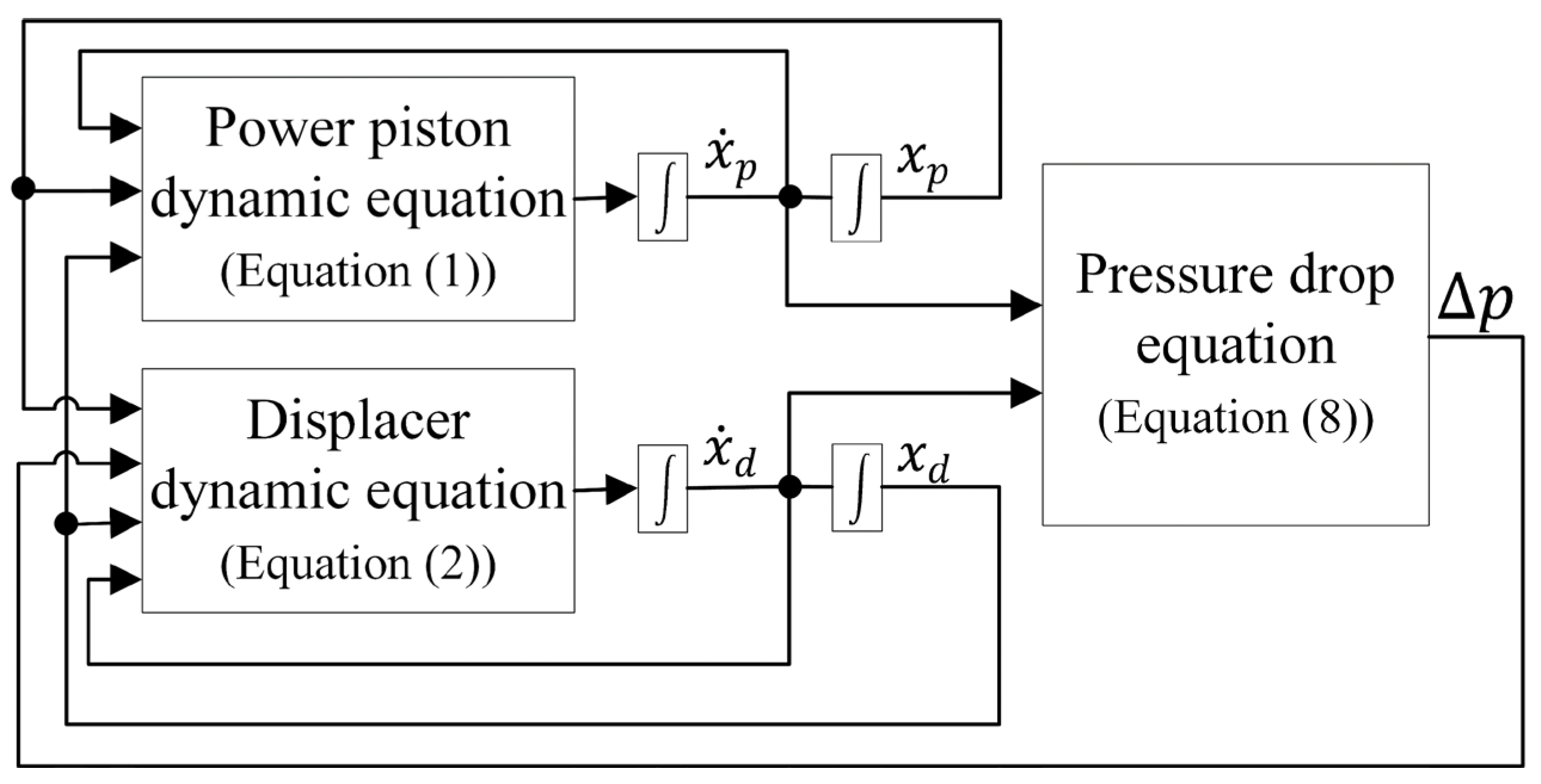
Based on the developed equations, the MATLAB Simulink® R2020b (The MathWorks, Natick, MA, USA) block diagram, which is used to model the FPSE, is shown in Figure 2.

3.2. Results

Now, the proposed dynamic model of the FPSE needs to be validated. The presented FPSE system is a RE-1000 Stirling engine (NASA Lewis Research Center Cleveland, OH, USA) [18]. Based on the input data of Table 2, the results of the model are validated with the presented experimental data by Urieli and Berchowitz [4] and are shown in Table 3.
As can be seen in Table 3, the results given by the presented FPSE dynamic model are close to the experimental ones for the output power, frequency, and amplitude ratio. However, a difference of 20% remains for the phase angle. This difference may be explained by the considered hypothesis in the present model: on the one hand, the hypothesis that the gas behaves a reversible and adiabatic path in both buffer and displacer gas spring spaces, and on the other hand, the fact that the displacer gap fluid flow is not yet considered at this level. Because the present study is focused on the effect of the enthalpy pumping and since the models permit to compute the produced energy with good accuracy, it will be considered valid as the FSPE dynamic model for the further computation in the present study.
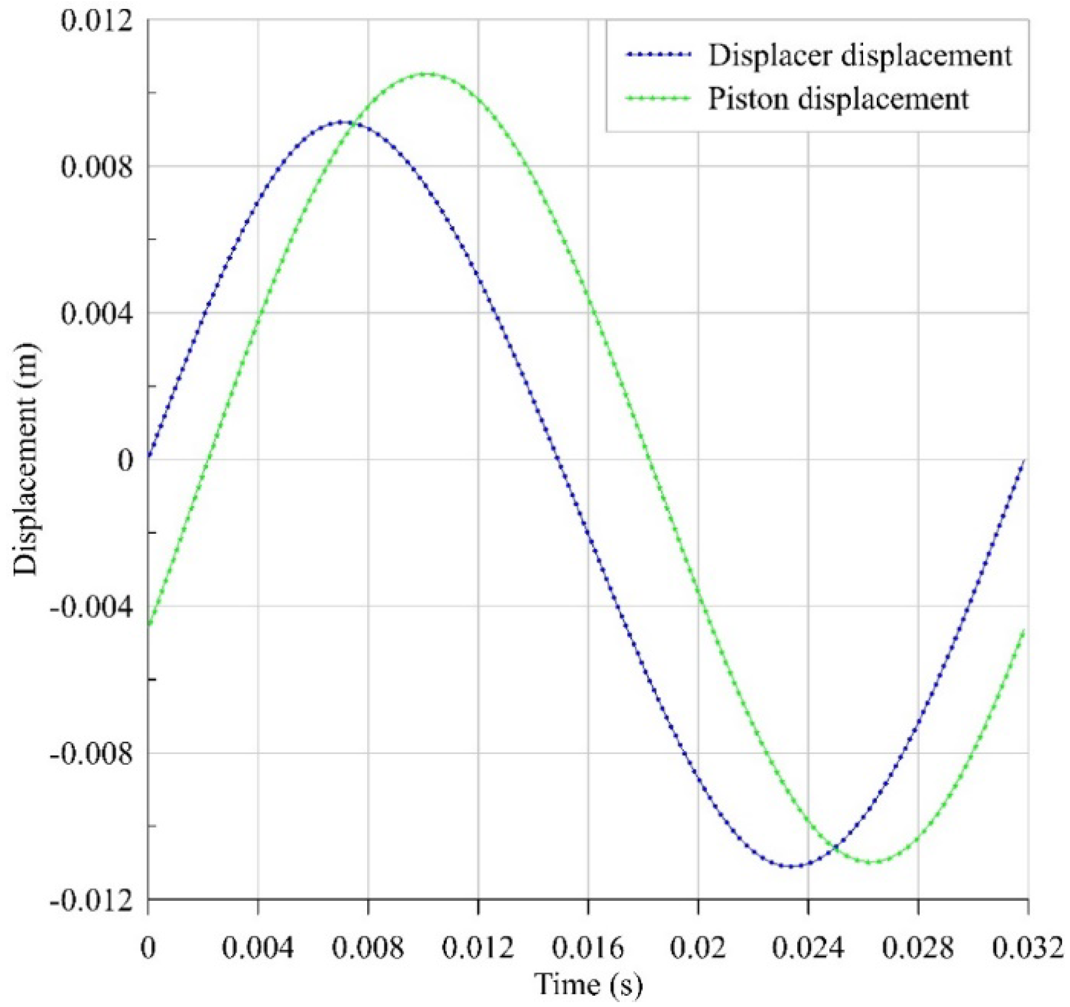
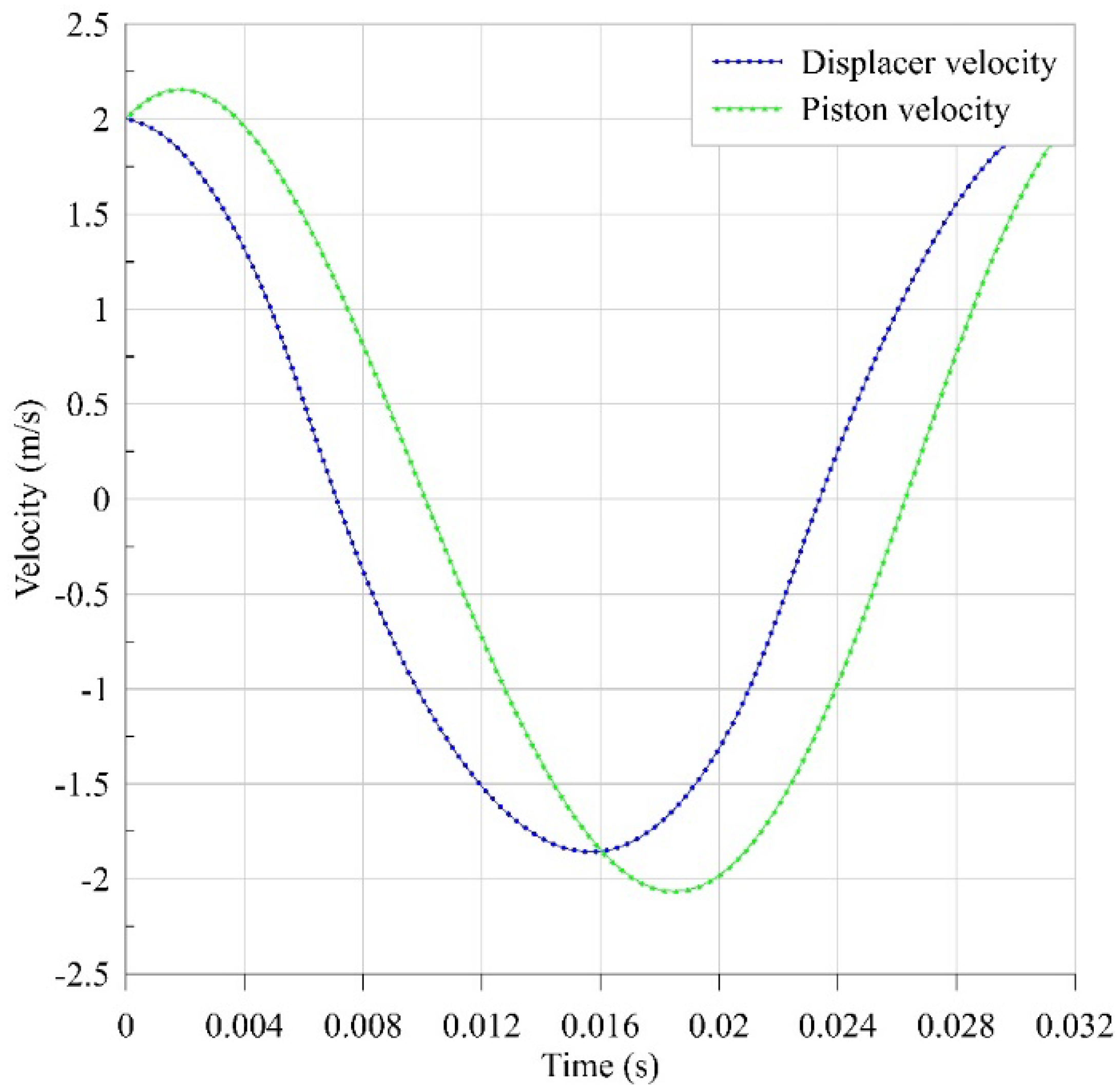
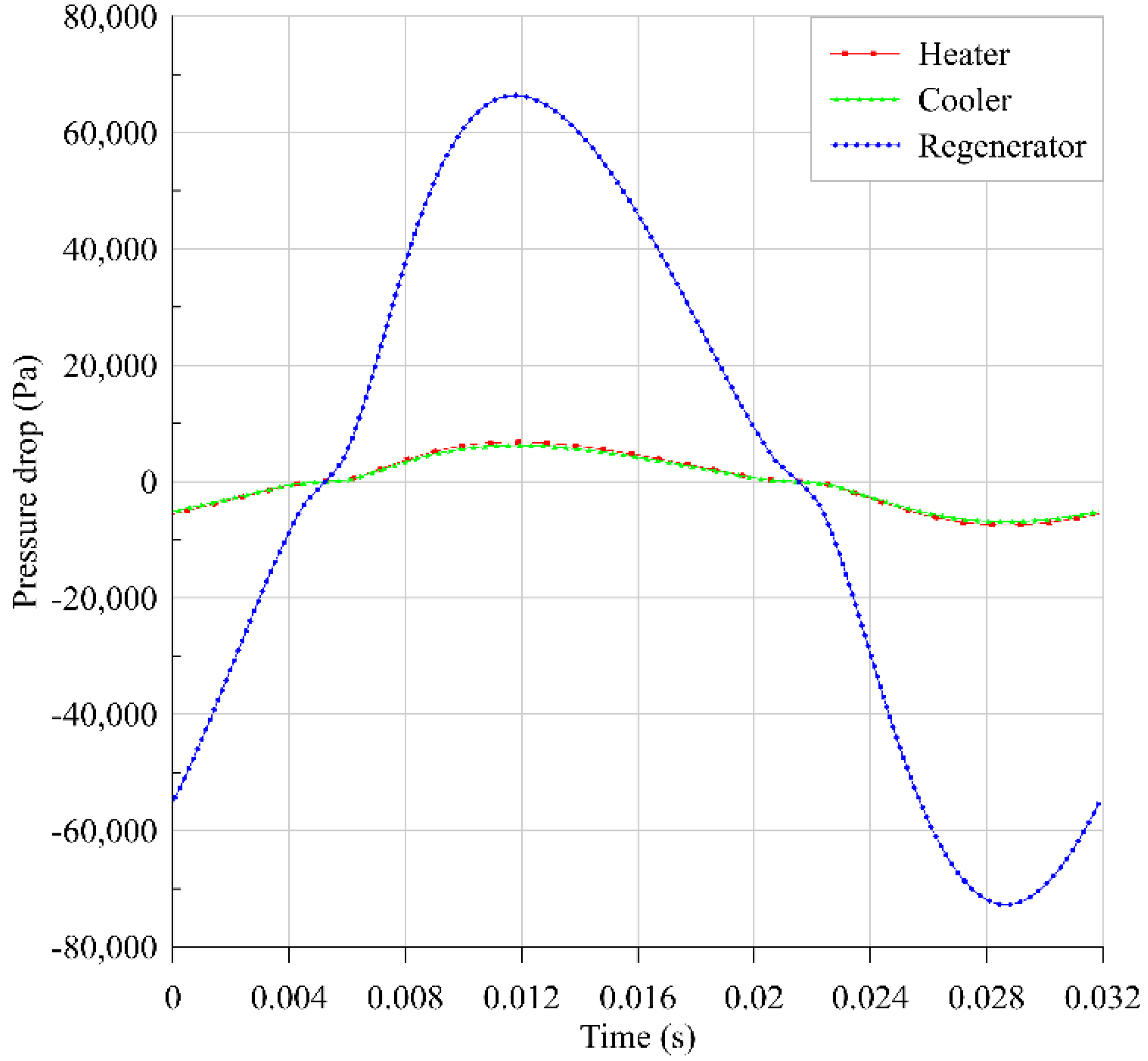
The results of the FPSE modeling for one cycle in a steady-state mode are presented in Figure 3, Figure 4 and Figure 5. These results are extracted after a few cycles in which the system meets its steady conditions.
Based on the displacement and velocity figures (Figure 3 and Figure 4) for the pistons, the behavior of the system is nearly sinusoidal as expected. As shown in the Figure 5, due to its porous media, the regenerator has the greatest pressure drop. Furthermore, the pressure drop associated with the heater and cooler are of the same order of magnitude and are much smaller than the pressure drop associated with the regenerator.

4. Enthalpy Pumping through Displacer Gap

Now, based on the developed dynamic model of the FPSE, the enthalpy pumping can be computed. The input data used in this section are identical to those used in the FPSE simulation (Table 2). Enthalpy pumping happens due to the short-circuit-like flow between the compression and the expansion spaces. This short-circuit-like flow through the cylinder-displacer gap is due to the instantaneous pressure difference between the compression and expansion spaces as well as to the displacer periodic motion. First of all, one should notice that the enthalpy pumping value affects the performance of the Stirling engine: less enthalpy pumping means better engine performances and vice versa. However, the enthalpy pumping does not directly represent a value to be deduced from the computed engine useful work obtained without this gap flow effects. The enthalpy pumping appears as a criterion that one must reduce for better engine performances. In this goal, reducing the displacer-cylinder gap reduces the flow through, but it enhances the fluid flow viscous friction in the gap. Hence, there are prior optimal values of this gap that depend on the engine functioning parameters and also on the working fluid and the temperature, and the pressure levels.
Two methods may be used to compute the enthalpy pumping that are the one-way (or decoupled) method or the two-way (or coupled) method. In fact, the gas flow through the displacer gap and the compression-expansion spaces pressure difference are interconnected, and each affects the other, as will be shown in the following sections. In the coupled method, which is an iterative method, the gas leakage flow computed in each iteration is used to correct the spaces’ pressure difference for the next iteration. The coupled model is more effective since it appears to be closer to the actual physical effect. One of the goals of the present work is to compare the result given by the coupled and the decoupled models. The decoupled method is considered in Section 4.1 using the approach of Mabrouk et al. [7,8] for the computation of the gas flow through the displacer gap. The coupled method is considered in Section 4.2, and it is based on the Hagen–Poiseuille equation approach for the gas leakage computation.

4.1. Decoupled Model

4.1.1. Methodology

The decoupled model developed here is an adaptation of the general study of Mabrouk et al. [7,8] to the special case of the FPSE. At first, the dynamic model (Equations (1) to (8)) of the FPSE is developed separately, and the required data (velocities, pressures, and displacements of the different interior components and spaces) are extracted. Then, the displacer gap gas flow is computed as well as the resulting enthalpy leakage. The flowchart of the decoupled model is shown in Figure 6. As can be seen in Figure 6, there is no coupling here since the engine dynamic simulation, and the displacer-cylinder gap flow computations are performed sequentially without any computation iterative schema.
Figure 7 shows the schematic of the gap with respected coordinates.
The formulation of the momentum and energy equation of the fluid flowing in the gap is developed based on the coordinates shown in Figure 7. As can be seen in Figure 7, two coordinates are defined: one stationary coordinate ( z ), related to the cylinder, and one moving coordinate ( z d ), related to the displacer.
It is assumed that the temperature variation along z and z d axis is linear with a slope equal to Γ = ( T e T c ) / L d . Based on this assumption and also on the fact that the gas flow between the compression and the expansion spaces related to the displacer, displacement introduces a periodic boundary condition on the cylinder and the displacer surfaces. The respective displacer and cylinder temperatures can be divided, concerning the time t, into an oscillating part and a constant part. They can be identified as [7]:
T c ( z , r , t ) = T r e f Γ z + T ˜ c ( r , t )
T d ( z d , r , t ) = T r e f Γ z d + T ˜ d ( r , t )
z d = z x d (   t )
T d ( z , r , t ) = T r e f Γ z + Γ x d ( t ) + T ˜ d ( r , t )
T f ( z , r , t ) = T r e f Γ z + T ˜ f ( r , t )
T r e f is the reference temperature, which is the cylinder temperature at z = 0 , and x d ( t ) is the displacer position.
For the fluid flow into the cylinder-displacer gap, based on the periodic displacer motion and the compression and expansion spaces pressure variations and assuming fully developed flow in the gap, the gas pressure, the gas flow velocity, the displacer position, and the displacer velocity can also be defined as
P f ( z , t ) = P 0 ( z ) + P ˜ f ( z , t )
u f ( r , t ) = u ˜ f ( r , t )
x d ( t ) = x ˜ d ( t )
x ˙ d ( t ) = x ˙ ˜ d ( t )
Notice that for the Stirling general case, the displacer position x d ( t ) that appears in Equations (12) and (17) is imposed by the engine mechanism following a predefined choice (e.g., Rhombic mechanism). For the present case of FPSE, this displacer position is not imposed but obeys the dynamic model that was defined by Equations (1) and (2).
With the hypothesis mentioned above of laminar and fully developed flow in the gap, the momentum and energy equations for the fluid flow inside the gap can be written as [7]
u ˜ t = 1 ρ f 0 P ˜ z + υ f 0 ( 2 u ˜ r 2 + 1 r u ˜ r )
T ˜ f t + T f 0 z u ˜ T f 0 β 0 ρ f 0 C p f 0 P t = α f 0 ( 2 T ˜ f r 2 + 1 r T ˜ f r )
Heat conduction in displacer and cylinder can be considered by the following equations:
T c t = α c 0 ( 2 T c r 2 + 1 r T c r )
T d t = α d 0 ( 2 T d r 2 + 1 r T d r )
To solve all these equations, the boundary conditions should be defined. For the gas velocity, the non-slip boundary condition is applied:
u f ( R d , t ) = x ˙ d ( t )
u f ( R c , t ) = 0
Relating to the conductive heat transfer concerning the radial direction in the displacer and the cylinder, since the frequency of the surface periodic boundary layers in the cylinder and the displacer are relatively high, the respective penetration depths, δ c and δ d , are small. Hence, one may assume that in the cylinder and displacer, the respective penetration depths, δ c and δ d , are steady and are not affected by the gas flow inside the gap. It gives the two following boundary conditions:
T ˜ c ( R c + δ c , t ) = 0
T ˜ d ( R d δ d , t ) = 0
On the contact surfaces with the flowing gas, it can be assumed that the temperature of the latter is equal to the respective surface temperature of the cylinder and the displacer:
T c ( z , R c , t ) = T f ( z , R c , t )
T d ( z , R d , t ) = T f ( z , R d , t )
On these contact surfaces, one had to consider also the heat flux continuity. It gives the two following boundary conditions:
K c 0 T c ( z , R c ) r = K f 0 T f ( z , R c ) r
K d 0 T d ( z , R d ) r = K f 0 T f ( z , R d ) r
At this level, all the governing Equations (10)–(22) and the boundary conditions (23)–(30) are known for the cylinder, the displacer, and the fluid that flows in the gap. Then, the system of the equations can be solved based on the study by Mabrouk et al. [7,8] using a perfect gas assumption. The final enthalpy pumping expression based on Mabrouk et al. [7,8] is as follows:
H ˙ p u m p i n g = 2 π R d R c ( ρ f 0 C p f 0 u f ( T f ) ) r d r
However, from the author’s point of view, since the enthalpy flow in both sides (from compression to expansion space and vice versa) should be taken into account as enthalpy pumping and these two values should not neutralize each other’s effect, the absolute value of the fluid speed u f is considered in the present study:
H ˙ p u m p i n g = 2 π R d R c ( ρ f 0 C p f 0 | u f | ( T f ) ) r d r
Equation (32) physically represents the arithmetic sum of the instantaneous total enthalpy that crosses the displacer-piston gap. T f will first considered in the equation according to the study of Mabrouk et al. [7] and will also be replaced with ( T e T c ) to be similar to the method that is used for the decoupled model. This provides two methods of enthalpy calculation for the decoupled model that will be compared with the developed coupled model. As stated above, it should be noted that this value of the enthalpy pumping that will be calculated based on Equation (32) is not the engine net power loss value that will be taken into account but just the total enthalpy that will be transferred through the gap. This is the reason that the gas velocity in the gap in both directions (from compression space to expansion space and vice versa) is assumed to be positive, and | u f | is used for enthalpy pumping computations. To have a better view of the enthalpy and its real effect on the system as a loss, it should be considered in the frame of a complete thermodynamic model.

4.1.2. Results

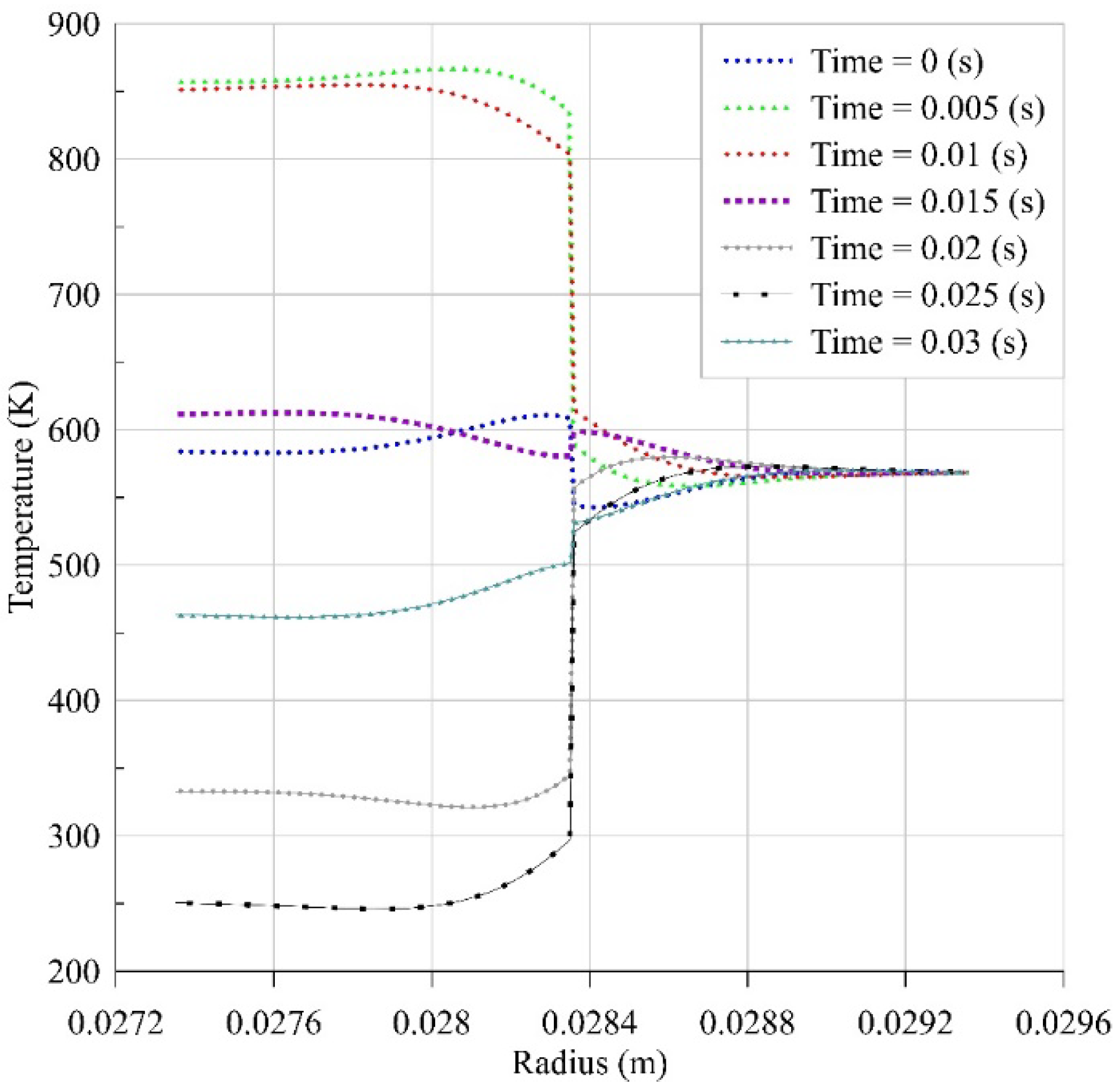
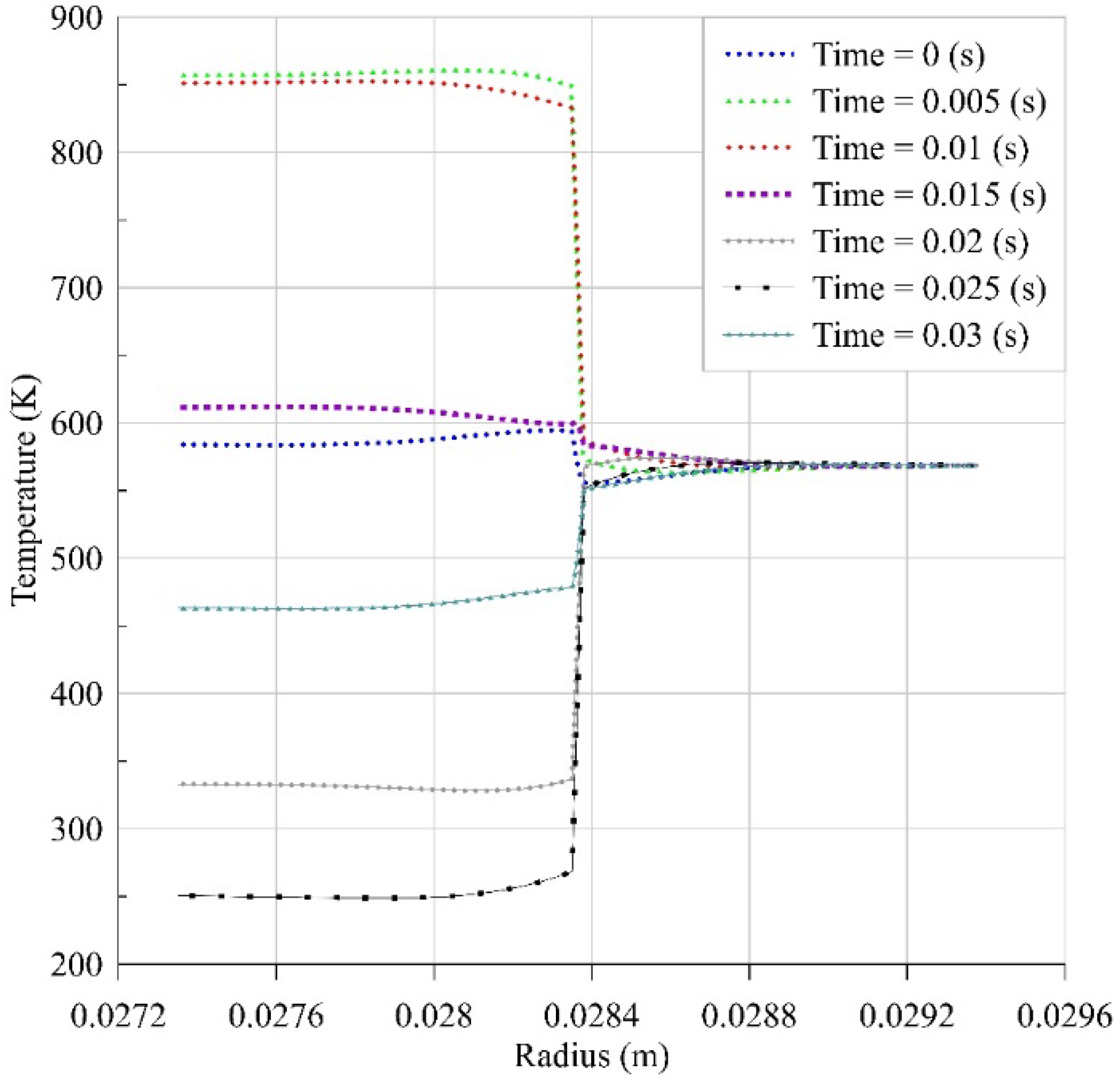
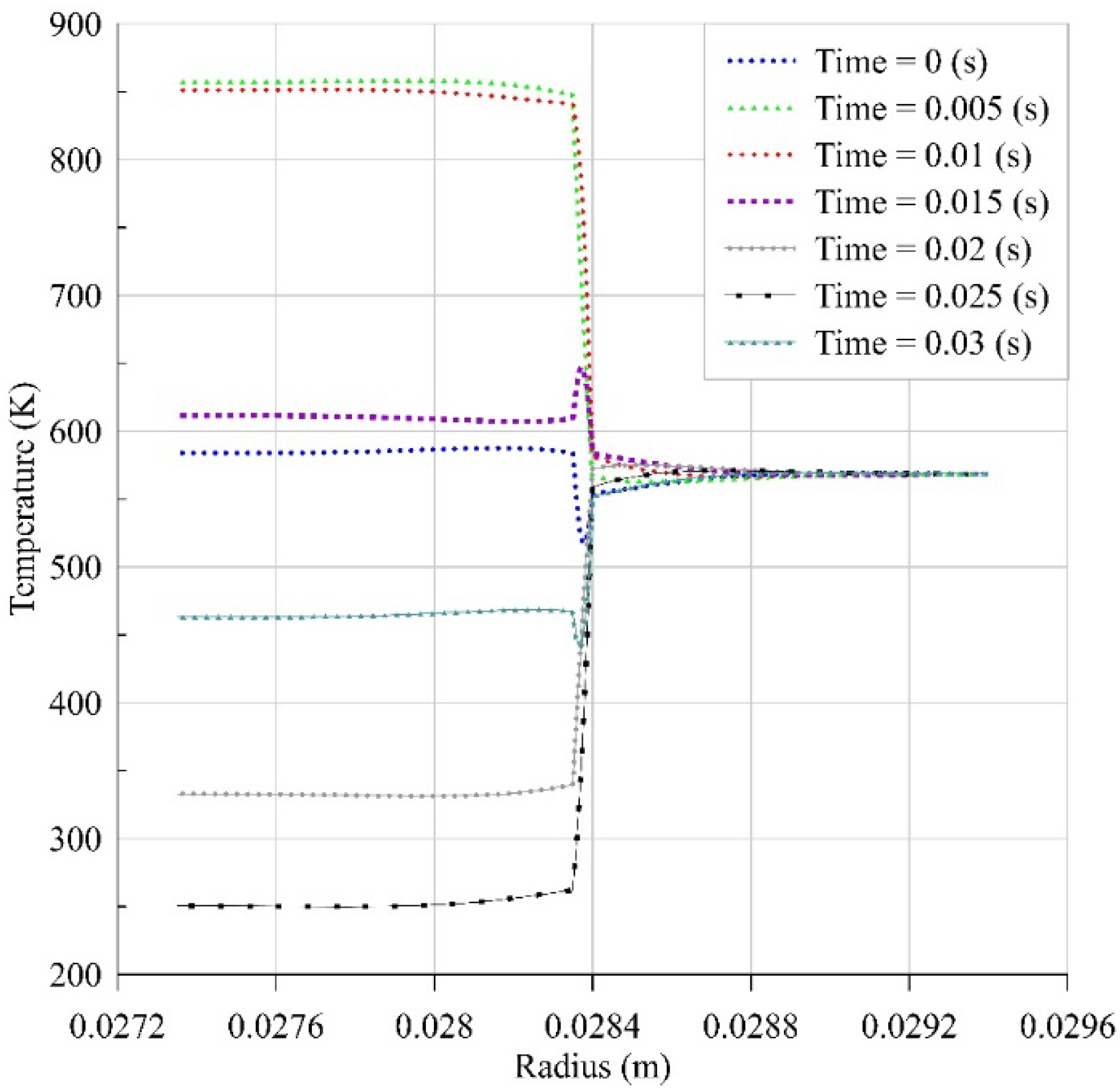
Now, the results of the decoupled model are presented. As can be seen in Equation (32), the gas flow temperature in the gap ( T f ) is required to calculate the enthalpy pumping through the original equation (Equation (32)). Thus, the temperature variations at different times and different gap sizes are presented in Figure 8, Figure 9, Figure 10 and Figure 11.
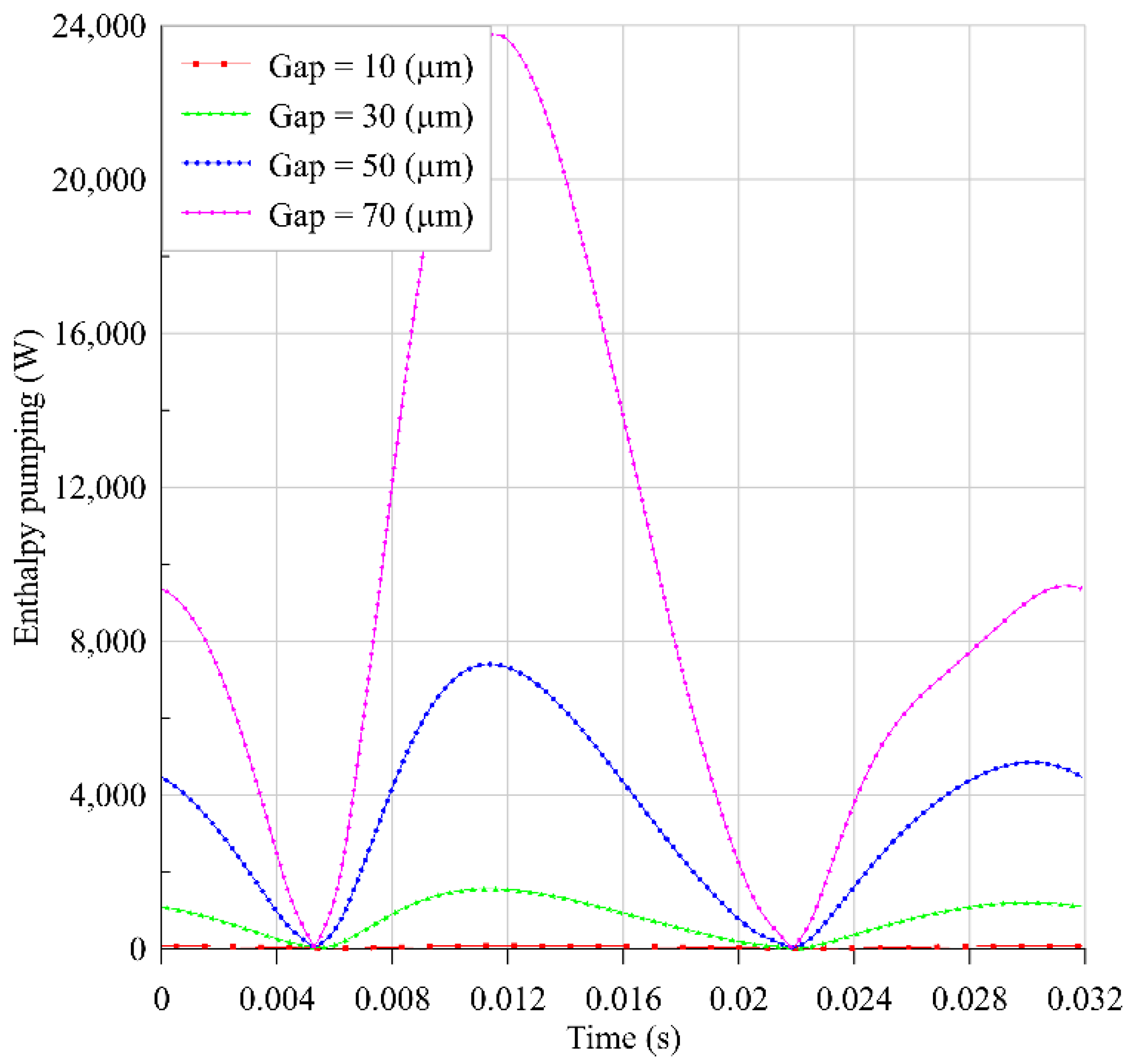
As shown in Figure 8, Figure 9, Figure 10 and Figure 11, the gas follows the boundary conditions and has a continuous temperature. By decreasing the gap size, the shape of the gas temperatures in the gap is getting more linear. Thus, as can be seen in Figure 8, for a gap equal to 10 μm, the gas temperature in the gap, which starts at 0.02835 (m), is almost linear at different times. Another important point is that for large gaps such as 70 μm, which can be seen in Figure 11, the maximum gas temperature in the gap gets so high/low that it may not be physically correct. It seems that from a physical point of view the recognized discrepancies are due to the fact that in the decoupled model, the computed gas leakage during a computing step is not considered for adjusting the pressure drop in the following computing step. This fact induces the cumulative error found in the final computed values of temperatures and pressures in the gap and in the compression and expansion spaces. These results will be discussed later in detail. Here, it may be concluded that using T f in Equation (32) might not be precise enough for large gaps. Now, based on these temperatures ( T f ) and also on the idea of replacing T f with ( T e T c ) that was explained after Equation (32), the enthalpy pumping is calculated through these methods for different gap sizes, and the results for a steady cycle of the FPSE are presented in Figure 12 and Figure 13.
The results of the decoupled model are in the same order as Mabrouk et al. [7] achieved in their research studies. As can be seen in Figure 12 and Figure 13, the computed values of the enthalpy pumping are too high, especially with the method of T f computation. A part of this problem may be due to the unrealistic computed gas temperatures in the gap, as already discussed. Having an enthalpy pumping with an instantaneous maximum value of 24 kW for an FPSE with a net power of 1 kW, as it is shown in Figure 12, cannot be physically explained. Moreover, the maximum values around 7.5 kW in Figure 13 may not be realistic. This might be due to the fact that there is no interaction between the enthalpy pumping model and the FPSE dynamic model.
These results on Figure 12 and Figure 13 confirm that the fact of omitting to correct the pressure drop during the computing loop leads to unrealistic physical values. One may be tempted by inducing such a correction in the computing loop, but the heaviness of the model (Equations (10)–(32)) to run between each two very close time steps induces very long computing time durations that are incompatible with an optimization approach of the whole systems with FPSE.
All these come to the point that the decoupled model may not be the most accurate one for all the conditions, especially when the gap size is large, and another method of enthalpy pumping computation should be developed. Thus, a simpler but accurate coupled model to compute the enthalpy pumping will be developed in the next section to consider the interaction between the enthalpy pumping model and the FPSE model.

4.2. Coupled Model

4.2.1. Methodology

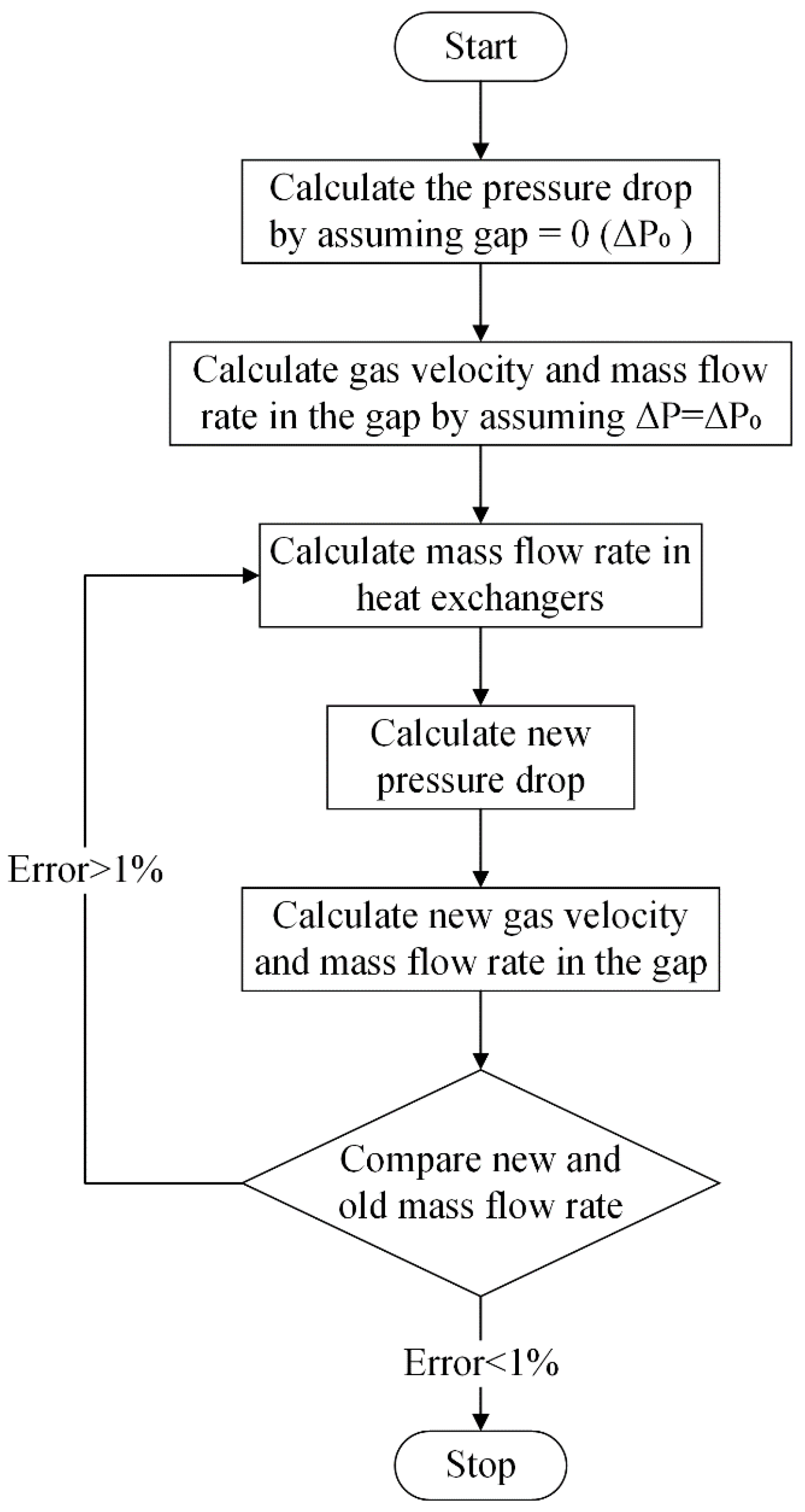
In order to have a better estimation of the enthalpy pumping, a new method to calculate it which is based on the instantaneous coupling between the FPSE dynamic model and enthalpy pumping model is developed in this section. In the coupled model, an iterative loop is set up to correct the pressure difference between the compression and expansion spaces, as shown in the Flowchart of Figure 14.
In fact, the pressure difference that stands between the compression and expansion spaces depends on the gas velocity through the engine Regenerator–Cooler–Heater path (Figure 1), and this velocity also depends on the gas leakage through the gap that obeys the compression-expansion pressures difference. The interrelationship between these two effects explains the need for an iterative computation procedure.
To calculate the enthalpy pumping in the coupled model, the first important parameter that should be calculated is the average gas velocity in the gap with respect to r . To calculate this velocity at each time t , the above-mentioned iterative computing loop is performed starting with a compression-expansion pressure difference Δ P 0 which is computed assuming no-gas flow leakage through the gap, and the gas mass flow through the Heater–Regenerator–Cooler path (Figure 1) using Darcy law with a classic expression of friction coefficient (Equation (8)). Then the gas velocity in the displacer-cylinder gap is computed as follows: assuming that the flow of the gas inside this gap consists of an annular Poiseuille flow, the momentum differential equation of the fluid velocity is a Hagen–Poiseuille equation [19]:
1 r r ( r u f r ) = 1 μ P f z
The analytical solution of this equation is
u f ( r ) = Δ P 4 μ L d r 2 + D 1 l n r + D 2
To calculate the constants, boundary conditions are needed. For the gas velocity, the non-slip boundary condition is applied:
u f ( R d , t ) = x ˙ d ( t )
u f ( R c , t ) = 0
D 1 and D 2 can be calculated based on these boundary conditions as
D 1 = Δ P 4 μ L d ( R c 2 R d 2 ) x ˙ d l n R c / R d
D 2 = Δ P 4 μ L d ( R d 2 l n R c R c 2 l n R d ) + x ˙ d l n R c l n R c / R d
The mass flow rate in the gap is computed with the gas velocity given by Equations (34), (37), and (38). Then, to start the next iteration, this mass flow is subtracted from the former mass flow that passes through the Heater–Regenerator–Cooler path. Now, based on this new mass flow rate, the new pressure drop Δ P is calculated (Equation (8)) to start a new iteration. This iterative procedure shown in Figure 14 is carried out for each time step and allows to rectify the mass flow rates by considering the leakage mass flow rate between the expansion and compression spaces.
When the iteration loop converges, on the one hand, the resulting Δ P is used for the displacer free-motion computation following Equations (1) and (2), and on the other hand, the resulting gap mass flow is used for the enthalpy pumping calculations.
Knowing the gas velocity in the gap, the advected (i.e., transported) enthalpy by this gas flow may be deduced [7]:
H ˙ p u m p i n g = 2 π R d R c ( ρ f 0 C p f 0 | u f | ( T e T c ) ) r d r
Knowing the enthalpy pumping, and depending on the displacer motion direction, the temperature of the expansion or the compression space is corrected using a heat balance. In fact, for each space, the total entering thermal energy is constituted by the enthalpy rate Q ˙ i n of the gas that flows through the Cooler–Regenerator–Heater path and the enthalpy rate H ˙ g a p of the gas that flows through the displacer-cylinder gap. This balance is written as follows:
( Q ˙ i n + H ˙ g a p ) W ˙ = C v d d t ( m T )
Notice that in the current specialized literature, based on the best knowledge of the authors, this temperature correction has never been done. Furthermore, notice the special case that the FPSE constitutes in this frame related to the work W ˙ that appears in the left term of this balance: this work interacts with the free movement of the displacer as described by Equation (2).

4.2.2. Results

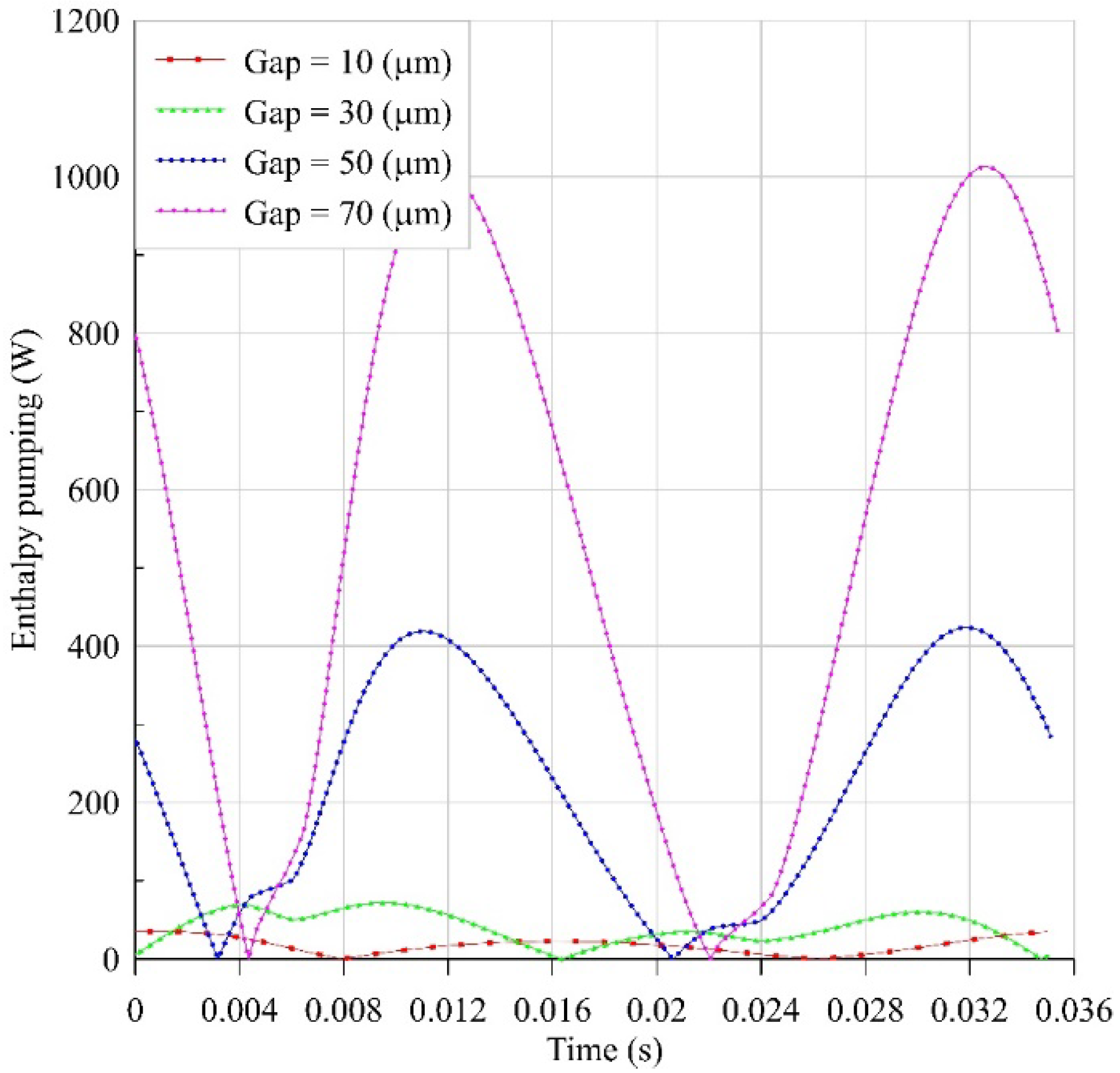
The results of the coupled enthalpy pumping model at different gap sizes are presented in Figure 15.
As can be seen in Figure 12, Figure 13, and Figure 15, the similar behavior for the coupled and decoupled models is that the enthalpy pumping is increasing dramatically with the gap size increment.
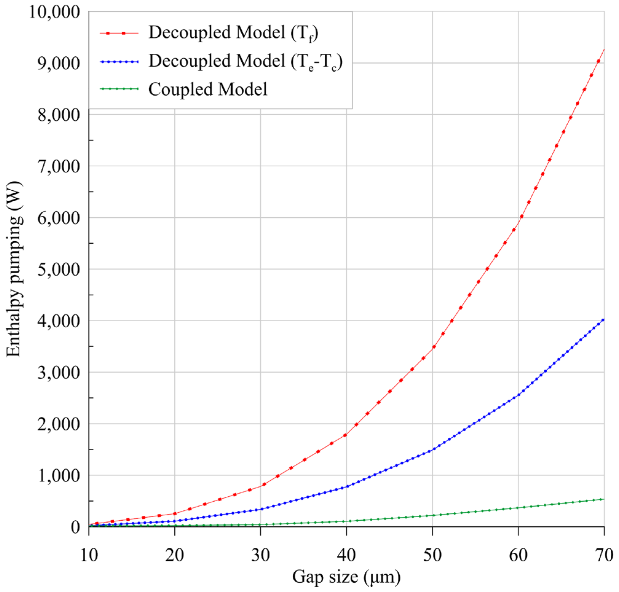
To have a better comparison between the coupled and decoupled models, the time average values of the enthalpy pumping for one cycle are shown in Figure 16 for a gap of 10–70 µm. Although the fact that the decoupled model gives more details about the gas flow in the gap, it is important to note that for a 1 kW Stirling engine, the amount of enthalpy pumping, which is calculated based on the decoupled models and Equation (32), is too high. Indeed, the value of the enthalpy exceeds the total output power for gap sizes larger than ~ 30   μ m when it is calculated using T f and gap sizes larger than ~ 40   μ m when it is calculated using ( T e T c ) . This can be explained by the fact that it does not take into account the impact of gas leakage on the pressure drop and the temperatures in the compression and expansion spaces. Another important point is that with the gap size variations, since the results of the decoupled model do not have any effect on the Stirling model (on the contrary to the coupled model that will update the pressure drop and modify the dynamic model), the output power and dynamic behavior of the system remain unchanged. Thus, the output power, amplitude ratio, phase change, frequency, and pressure drop are not changed by considering the decoupled model. On the other hand, in the coupled model, all these operating parameters are affected by the enthalpy pumping, and conversely, this effect is reflected in the enthalpy pumping calculation. Moreover, as it can be seen in Figure 15, the values of enthalpy pumping calculated based on the coupled model are much more consistent compared to the decoupled models that are shown in Figure 12 and Figure 13 for a 1 kW FPSE. The same remark applies in Figure 16, where, even for large gap sizes, the average enthalpy pumping computed using the coupled model stays in a more consistent range.
The difference between the coupled and the decoupled model results is due to the gas leakage effect on the compression and expansion space that was ignored in the decoupled model. In the coupled model, this gas leakage affects the system behavior, and as a result, this effect will be reflected on the enthalpy pumping and does not allow it to increase as it is for the decoupled model. As a result, it can be concluded that the effect of the enthalpy pumping on the operating parameters of the Stirling Engine is too high to be neglected. Thus, a decoupled model may not be the best alternative to estimate enthalpy pumping values as was used by Mabrouk et al. [7,8]. In their approach, even if the gap flow computation is sophisticated (Equations (10)–(32)), their computation procedure is one-way based and shall be further considered in an iterative frame take into account the compression-expansion spaces pressure correction at each step.
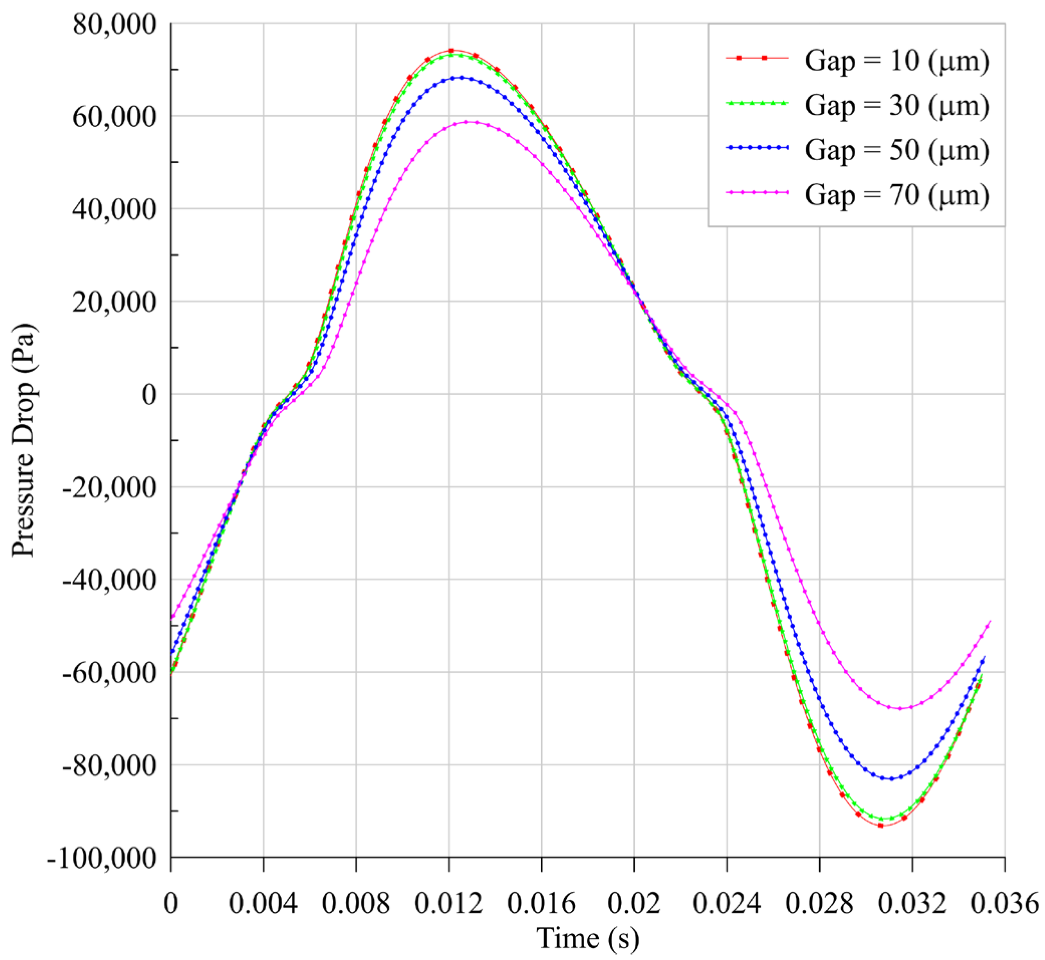
As already discussed, in the coupled model, the leakage will affect the system’s operating parameters. Here, this effect on three important parameters of the system is studied. The first is pressure drop. This parameter is affected by the gas leakage, as was already shown in Figure 14. The effect of gap size variations on the pressure drop is shown in Figure 17.
As can be seen in Figure 17, by gap size increment, the pressure drop is decreasing. The source of the pressure drop is the gas flow through the heat exchangers and regenerator. Due to the leakage and the short circuit flow between expansion and compression spaces, the gas flow through heat exchangers and regenerator decreases, and as a result, the pressure drop also decreases. As much as the gap size increases, the short circuit flow increases, resulting in the pressure drop decrement. This decrease of the pressure drop will decrease the leakage mass flow rate through the gap of the displacer.
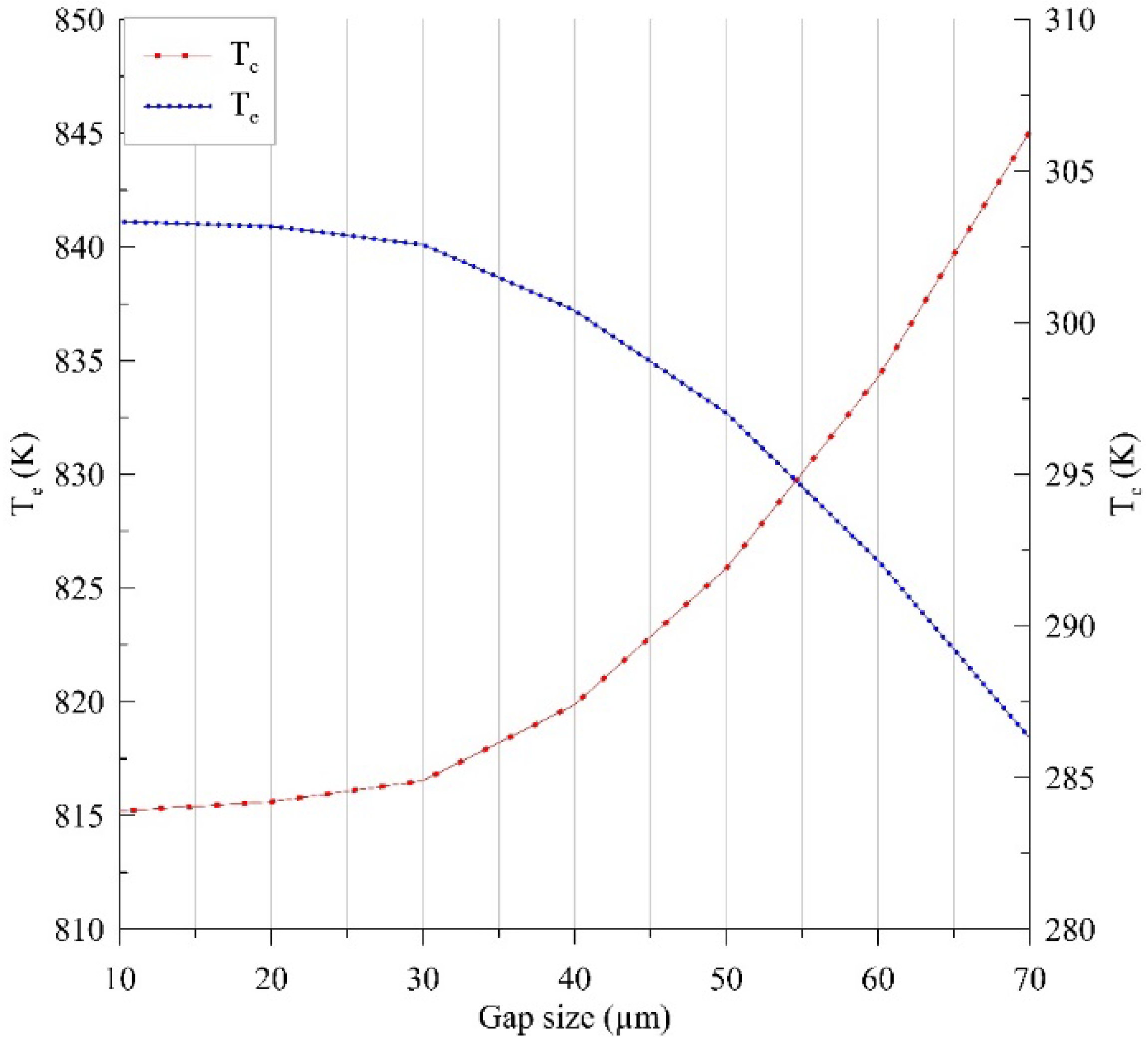
The second parameter that is studied here is the gas temperature in expansion and compression spaces. The average gas temperature in each space varies due to the gas leakage between two spaces according to the energy balance equation (Equation (40)). This temperature variation in different gap sizes is shown in Figure 18.
As can be seen in Figure 18, due to the gas leakage, the average gas temperature in expansion space decreases, and the average gas temperature in compression space increases. This temperature variation without any power production affects the system performance.
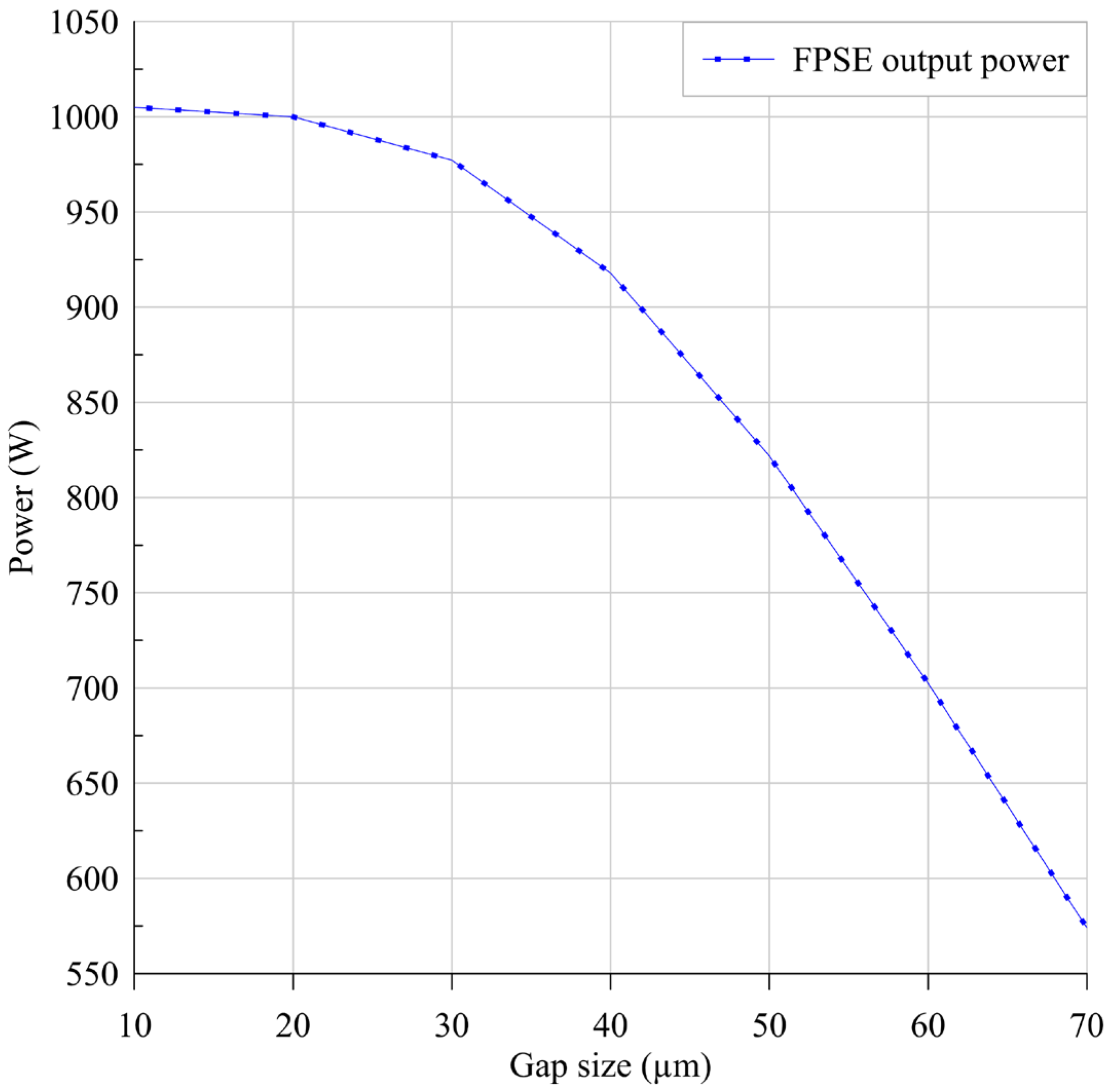
The output power is the last and the most important parameter on which the effect of the enthalpy pumping is studied. Both recently studied parameters affect this final output of the system. The effect of enthalpy pumping on the FPSE power production at different gap sizes is shown in Figure 19.
As shown in Figure 19, as much as the gap size and enthalpy pumping increase (as shown in Figure 16), the output power decreases. By gap size increment, since the gas leakage increases, the gas volume that already did work also decreases. Moreover, the temperatures of the expansion and compression spaces are affected due to this leakage. Thus, the output power of the system decreases because of these two effects.
Furthermore, the output power decrement rate has the same behavior as the enthalpy pumping increment rate (as shown in Figure 16), and by gap size increment, this rate is also growing. This rate, after around 40 μm of the gap size, gets almost constant.
As it is shown in Figure 19, the effect of the gap size on the output power is so significant that it cannot be ignored. These results confirm the inability of the decoupled model, proposed by Mabrouk et al. [7,8] and investigated in Section 4.1, to predict the correct enthalpy pumping values for the FPSE system.

5. Conclusions

In the present study, enthalpy pumping for an FPSE system was analyzed. At first, a nonlinear dynamic model of an FPSE was developed and validated. Then, a decoupled model to calculate the enthalpy pumping based on this dynamic model of the FSPE was developed. Two approaches for the decoupled enthalpy pumping calculation were also considered. After that, since the decoupled model did not present realistic results in all the conditions, an iterative coupled model was developed. In the coupled model, the effect of the gas leakage on three parameters was investigated. The first parameter was the pressure drop that, through an iterative procedure, was modified. The second studied effect was the thermal balance in compression and expansion spaces due to this leakage. In order to study this effect, the thermal balance in each space by taking into account the enthalpy pumping was considered in the system modeling. The last parameter was the FPSE produced power. After developing the coupled and decoupled models, the enthalpy pumping of each model during a cycle at different gap sizes was calculated, and the results were extracted. Then, to have a comparison between two developed models, the average values of the enthalpy pumping at different gap sizes were calculated, and the results were compared. Moreover, to show the effect of the coupled enthalpy pumping on the FPSE performance, the pressure drop, the average gas temperature in expansion and compression spaces, and the output power of the system at different gap sizes were shown.
The results presented two important points. The first point is that enthalpy pumping has a considerable effect on the system performance that cannot be neglected. Secondly, due to the coupling between the FPSE and the enthalpy pumping, it will be affected by the system behavior, and the enthalpy pumping value will not be in the same order as the decoupled model. The enthalpy pumping values in the decoupled model were really high compared to the produced power, and it is not realistic, as already discussed.
As a final result, it can be concluded that the decoupled enthalpy pumping method, as it was proposed by other researchers, is not a precise model. Thus, to evaluate the enthalpy pumping, the proposed coupled method in the present study should be considered. This model is less time-consuming compared to the decoupled model and due to the much fewer mathematical computations, easier to understand and apply.
Moreover, considering the enthalpy pumping in a thermodynamic FPSE coupled model instead of the dynamic one may have more effect on both thermic and dynamic behaviors of the system, which can be studied later.

Author Contributions

Conceptualization, M.M. and M.T.M.; methodology, M.M. and M.T.M.; software, M.M.; validation, M.M.; formal analysis, M.M.; investigation, M.M.; data curation, M.M.; writing—original draft preparation, M.M.; writing—review and editing, M.M., M.T.M. and A.K.; visualization, M.M.; supervision, A.K.; project administration, B.R. and T.B. All authors have read and agreed to the published version of the manuscript.

Funding

This research received no external funding.

Conflicts of Interest

The authors declare no conflict of interest.

Nomenclature

A Area, m2 x ¨ Acceleration, m/s2
C Clearance, m z Axis
C f Darcy friction factorGreek symbols
C p Specific heat capacity at constant pressure, J/( kg·K) α Thermal diffusivity, m2/s
C v Specific heat capacity at constant volume, J/( kg·K) β Isochoric thermal pressure coefficient, 1/K
d Diameter, m Γ Temperature variation, K/m
F Force, N γ Specific heat ratio
H ˙ Enthalpy rate, W δ Thickness, m
K Thermal Conductivity, W/(m·K) μ Dynamic viscosity, Pa.s
L Length, m ν Kinematic viscosity, m2/s
M ; m Mass, kg   ρ Density, kg/m3
P Pressure, PaIndex and exponent
Q ˙ Heat transfer rate, W 0 Time average
R Gas constant, Radius, m   ˜ Oscillating part
r Radius, m   b Buffer
R e Reynolds number   c Compression, Cylinder
T Temperature, K   d Displacer
t Time, s   e Expansion
u Gas velocity, m/s   f Flow
V Volume, m3 g s Gas spring
V ˙ Volumetric rate, m3/s   h Heater
W ˙ Work rate, W   k Cooler
X Maximum stroke, m   p Power piston
x Displacement, m   R Regenerator
x ˙ Piston velocity, m/s w Wire

References

  1. Zare, S.; Tavakolpour-Saleh, A.R. Frequency-Based Design of a Free Piston Stirling Engine Using Genetic Algorithm. Energy 2016, 109, 466–480. [Google Scholar] [CrossRef]
  2. Wang, K.; Sanders, S.R.; Dubey, S.; Choo, F.H.; Duan, F. Stirling Cycle Engines for Recovering Low and Moderate Temperature Heat: A Review. Renew. Sustain. Energ. Rev. 2016, 62, 89–108. [Google Scholar] [CrossRef] [Green Version]
  3. Sauer, J.; Kuehl, H.D. Theoretically and Experimentally Founded Simulation of the Appendix Gap in Regenerative Machines. Appl. Therm. Eng. 2020, 166, 114530. [Google Scholar] [CrossRef]
  4. Urieli, I.; Berchowitz, D. Stirling Cycle Engine Analysis; Adam Hilger Ltd.: Bristol, UK, 1984; ISBN 978-0996002196. [Google Scholar]
  5. Redlich, R.W.; Berchowitz, D.M. Linear Dynamics of Free-Piston Stirling Engines. Proc. Inst. Mechan. Eng. Part Power Proc. Eng. 1985, 199, 203–213. [Google Scholar] [CrossRef]
  6. Walker, G.; Senft, J.R. Free-Piston Stirling Engines. In Free Piston Stirling Engines; Springer: Berlin/Heidelberg, Germany, 1985; pp. 23–99. [Google Scholar]
  7. Mabrouk, M.T.; Kheiri, A.; Feidt, M. Displacer Gap Losses in Beta and Gamma Stirling Engines. Energy 2014, 72, 135–144. [Google Scholar] [CrossRef]
  8. Mabrouk, M.T.; Kheiri, A.; Feidt, M. Effect of Leakage Losses on the Performance of a β Type Stirling Engine. Energy 2015, 88, 111–117. [Google Scholar] [CrossRef]
  9. Rios, P.A. An Approximate Solution To the Shuttle Heat-Transfer Losses in a Reciprocating Machine. J. Eng. Power 1971, 93, 177–182. [Google Scholar] [CrossRef]
  10. Berchowitz, D.M. Stirling Cycle Engine Design and Optimisation. Ph.D. Thesis, University of the Witwatersrand, Johannesburg, South Africa, 1986. [Google Scholar]
  11. Baik, J.H.; Chang, H.M. An Exact Solution for Shuttle Heat Transfer. Cryogenics 1995, 35, 9–13. [Google Scholar] [CrossRef]
  12. Chang, H.M.; Park, D.J.; Jeong, S. Effect of Gap Flow on Shuttle Heat Transfer. Cryogenics 2000, 40, 159–166. [Google Scholar] [CrossRef]
  13. Kotsubo, V.; Swift, G. Thermoacoustic Analysis of Displacer Gap Loss in a Low Temperature Stirling Cooler. In Proceedings of the AIP Conference Proceedings; American Institute of Physics: College Park, MA, USA, 2006; Volume 823, pp. 353–360. [Google Scholar]
  14. Pfeiffer, J.; Kuehl, H.D. New Analytical Model for Appendix Gap Losses in Stirling Cycle Machines. J. Therm. Heat Transf. 2016, 30, 288–300. [Google Scholar] [CrossRef]
  15. Majidniya, M.; Boileau, T.; Remy, B.; Zandi, M. Nonlinear Modeling of a Free Piston Stirling Engine Combined with a Permanent Magnet Linear Synchronous Machine. Appl. Therm. Eng. 2020, 165, 114544. [Google Scholar] [CrossRef]
  16. Majidniya, M.; Boileau, T.; Remy, B.; Zandi, M. Performance Simulation by a Nonlinear Thermodynamic Model for a Free Piston Stirling Engine with a Linear Generator. Appl. Therm. Eng. 2021, 184, 116128. [Google Scholar] [CrossRef]
  17. Majidniya, M.; Boileau, T.; Benjamin, R.; Zandi, M. Modélisation Thermo-Électrique d’un Moteur Stirling à Piston Libre et d’une Machine Synchrone Linéaire à Aimant Permanent Avec Sa Commande. In Proceedings of the congrès annuel de la Société Française de Thermique, Nantes, Toulouse, France, 3–6 June 2019. [Google Scholar]
  18. Schreiber, J. Testing and Performance Characteristics of a 1-Kw Free Piston Stirling Engine. NASA Technical Memorandum. 1983. Available online: https://ntrs.nasa.gov/citations/19830016765 (accessed on 20 March 2022).
  19. Batchelor, C.K.; Batchelor, G.K. An Introduction to Fluid Dynamics; Cambridge University Press: Cambridge, UK, 1959. [Google Scholar]
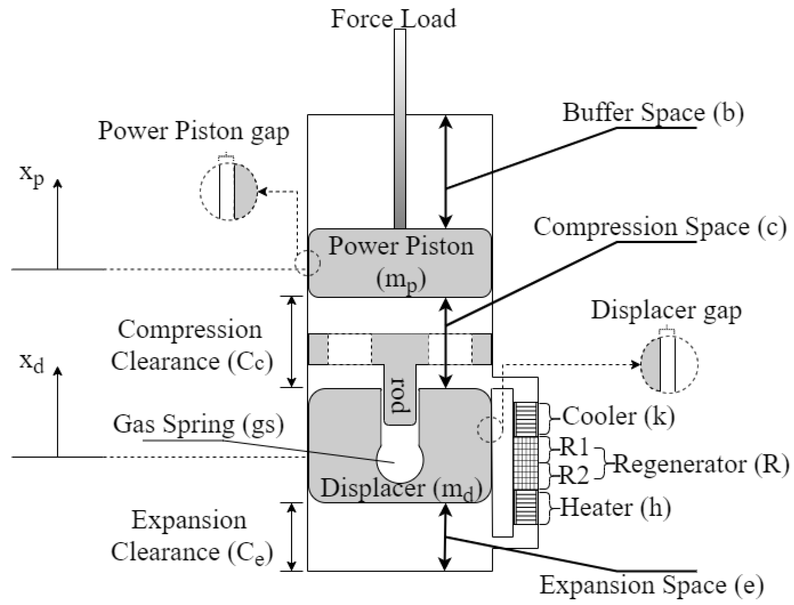
Figure 1. Mechanical schematic of the Free Piston Stirling Engine (FPSE).
Applmech 03 00021 g001
Figure 2. FPSE block diagram [15].
Applmech 03 00021 g002
Figure 3. Displacer and piston displacement.
Applmech 03 00021 g003
Figure 4. Displacer and piston velocity.
Applmech 03 00021 g004
Figure 5. Pressure drops in the exchangers.
Applmech 03 00021 g005
Figure 6. Flowchart of the decoupled enthalpy pumping model.
Applmech 03 00021 g006
Figure 7. Gap coordinates.
Applmech 03 00021 g007
Figure 8. Flow temperature in the gap = 10 μm.
Applmech 03 00021 g008
Figure 9. Flow temperatures in the gap = 30 μm.
Applmech 03 00021 g009
Figure 10. Flow temperature in the gap = 50 μm.
Applmech 03 00021 g010
Figure 11. Flow temperature in the gap = 70 μm.
Applmech 03 00021 g011
Figure 12. Decoupled enthalpy pumping at different gap sizes with T f .
Applmech 03 00021 g012
Figure 13. Decoupled enthalpy pumping at different gap sizes with T e T c .
Applmech 03 00021 g013
Figure 14. Flowchart of pressure drop correction based on the coupled model.
Applmech 03 00021 g014
Figure 15. Coupled enthalpy pumping at different gap sizes.
Applmech 03 00021 g015
Figure 16. Coupled and decoupled enthalpy pumping comparison.
Applmech 03 00021 g016
Figure 17. Effect of the gap size on the pressure drop.
Applmech 03 00021 g017
Figure 18. Effect of the gap size on the average gas temperature in the spaces.
Applmech 03 00021 g018
Figure 19. Effect of the gap size on the FPSE power production.
Applmech 03 00021 g019
Table 1. Calculating C f based on Reynolds number [15].
For Heater and Cooler: R e   < 2000 C f = 64 / R e
R e > 2000 C f = 0.316 R e 0.25
For Regenerator: R e < 60 C f = 4 × 10 ( 1.73 0.93 l o g R e )
60 < Re < 1000 C f = 4 × 10 ( 0.714 0.365 l o g R e )
R e > 1000 C f = 4 × 10 ( 0.015 0.125 l o g R e )
Table 2. FPSE input parameters [15].
T h 814.3 K d h 0.2362 cm C e 1.861 cm
T k 322.8 K d w 0.00889 cm V b   m e a n 2615 cm3
P m e a n 71 bars L k 7.92 cm V g s   m e a n 37.97 cm3
Porosity 75.9% L h 18.34 cm V R 56.37 cm3
m d 0.426 kg L R 6.44 cm   Wetted   perimeter k 115.2 cm
m p 6.2 kg A h 1.4898 cm2 Passage   dimension k 50.8 mm × 376 mm
d p 5.718 cm A k 2.6163 cm2 Passage   number k 135
d d 5.67 cm A R 8.745 cm2 X p 4.20 cm
d r o d 1.663 cm C c 1.83 cm X d 4.04 cm
Table 3. FPSE validation.
Frequency (Hz) Phase   Angle   ( ° ) Amplitude   Ratio   ( X d / X p ) Output Power (kW)
Exp. Results [4]30−42.51.061.00
Present Model31.25−33.750.9451.005
Publisher’s Note: MDPI stays neutral with regard to jurisdictional claims in published maps and institutional affiliations.