Article

Paint Coating Removal by Heating for High-Strength Bolted Joints in Steel Bridge and Its Influence on Bolt Axial Force

1
Japan Bridge Corporation, Kobe 650-0023, Japan
2
Graduate School of Engineering, Osaka University, Osaka 565-0871, Japan
3
Sumitomo Osaka Cement Co., Ltd., Osaka 551-0021, Japan
4
Furuichi Co., Ltd., Osaka 565-0832, Japan
*
Author to whom correspondence should be addressed.
Appl. Mech. 2021, 2(4), 728-738; https://doi.org/10.3390/applmech2040042
Submission received: 12 August 2021 / Revised: 22 September 2021 / Accepted: 26 September 2021 / Published: 30 September 2021
(This article belongs to the Special Issue Mechanical Design Technologies for Beam, Plate and Shell Structures)

Abstract

:
A series of experiments were carried out for developing a paint coating removal method for high-strength bolted joints in steel bridges. The paint-coated bolted joint specimens were heated to the target temperature of 200 °C by using a sheet-type ceramic heater. The maximum temperature of specimens could be controlled within 10% of the target value. The paint coating was easily removed by using general tools after heating. The behaviour of bolts with thermal expansion and shrinkage was monitored by strain gauges attached to the bolts during heating. It was estimated that the axial forces of the bolts were reduced by 2.6% of the initially installed axial forces, on average.

1. Introduction

Steel structures used in corrosion environments such as ships, buildings, bridges, and any other mechanical structures have risks of corrosion damage. The corrosion damage reduces the thickness of steel members so that the mechanical performances of steel members are reduced. Therefore, the steel structural members should be properly protected against corrosion damage. There are typical corrosion protection methods such as painting, Zn hot-dip galvanising, and thermal spraying. The most general corrosion protection method is paint coating.
The paint coating is applied to the surface of steel members with multiple layers. Firstly, the surface of the steel member is cleaned by grinding or blasting for ensuring adhesion between the undercoat of paint coating and the steel substrate. Then, the middle coat and topcoat are applied for achieving the required performance and durability. However, the paint coating of steel structures gradually deteriorates under severe corrosion environments. In the case of steel bridges in Japan, the service life of paint coating is determined to range from 15 years to 60 years depending on the corrosion environments [1]. In Japan and elsewhere, paint coating systems with a zinc-rich primer, an epoxy intermediate layer, and a polyurethane topcoat with long-term service life between 25 to 30 years have been reported [2]. Other reports have shown that the zinc-rich primer-based coating system may have 30 years of service life. Furthermore, the age of the coating might reach 55 to 80 years if the zinc-rich primer is not damaged [3].
However, the deteriorated paint coating should be repaired or renewed to protect the steel member under the coating. Then, it is important to clean the surface of the steel substrates properly because the remaining rust and other materials strongly reduce the performance of renewed paint coating [4]. For cleaning the steel surface, including the removal of the deteriorated paint coating, several mechanical methods such as grinding by power tools, blasting, and water jets are used [5]. However, the generation of dust and waste should be managed for the surrounding environments and the health conditions of workers. A chemical method with a paint coating removal agent is an effective countermeasure for collecting the dust and waste easily. However, the removed paint coating includes the viscous liquid of the agent. This means that the amount of waste is increased. Furthermore, impregnating the paint coating removal agent from the surface to the inside of the existing paint coating before removing it takes a long time. Therefore, the chemical method is not effective for removing thick paint coating or tight rust [5].
For solving these difficulties in paint coating-removal, several innovative methods have been developed and examined. Recently, laser paint stripping has been noted in the field of automobile and aircraft engineering [6]. Not only the single use of the laser, but also the combination of the water jet and the laser has been applied for paint coating removal [7]. Among the innovative paint coating removal methods, a thermal method with induction heating (IH) is expected as a countermeasure for the existing methods from the viewpoints of less dust, rapid work, and low environmental load [5]. That is, the paint-coated steel member is heated by high-frequency induction heating. The paint coating becomes easily removed by the temperature rise because the adhesion is decreased. It is widely used as a commercial method in several products such as storage tanks, pipelines, steel structures, ships, and offshore structures [8]. However, there are few reports of the academic study or investigation of paint coating removal by heating including the IH method. We previously conducted a fundamental investigation of the applicability of the induction heating to paint coating removal [9]. There are some construction reports of the application of the IH method to the paint coating removal of the steel bridges in Japan [10,11]. It is known that the IH method is reasonable for applying flat parts of steel members, but is difficult to apply to bolted joints with complicated shapes. Moreover, the influence of rapid temperature rise by the induction heating on the axial force of the bolts is unknown. Therefore, the application of the IH method to the bolted joints in steel bridges is limited.
As a countermeasure of this limitation to the IH method, this study aims to develop a paint coating removal method with heating as well as the IH method. However, the method in this study does not use induction heating. On the contrary, a slow but high-controllable heat source, which is a ceramic heater, is used for managing the temperature accurately. We previously confirmed the accurate controllability of the temperature in the heat treatment experiments of the specimens assuming the steel bridge members [12,13]. Furthermore, we experimentally examined the application of this ceramic heater for the paint coating removal of bolted joints specimens [14]. In this experiment, the accurate temperature control could be confirmed for the bolted joints. However, the influence of heating on the axial force installed into the bolts has not been sufficiently elucidated. In this study, the influence of heating for the paint coating removal on the axial force of the bolt was examined.

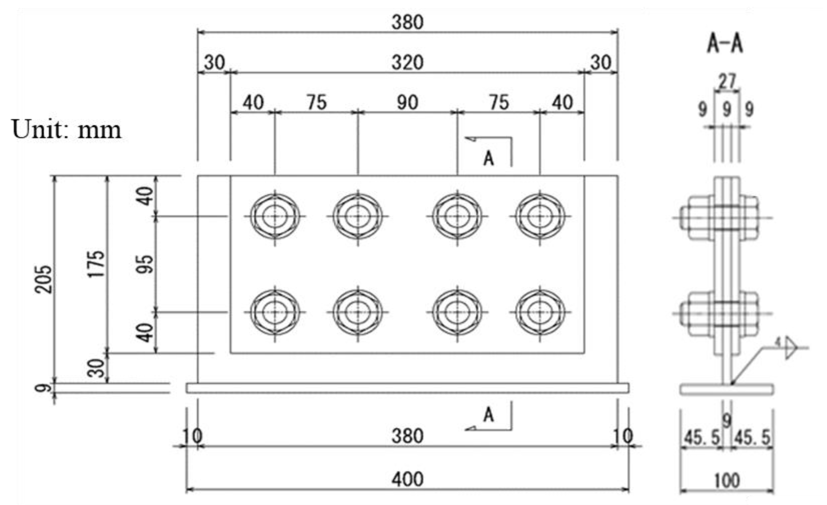
2. Experimental Specimen

Figure 1 shows the shape and dimension of the experimental specimen in this study. A base plate with 205 mm × 380 mm was sandwiched between two cover plates with 175 mm × 320 mm. A steel plate with 400 mm × 100 mm was welded to the base plate for preventing the rollover of the specimen. The material of these plates was SS400, and they were 9 mm thick. The base plate and cover plates had 2 × 4 bolt holes with a diameter of 24.5 mm. High-strength bolts of F10T and M22 were inserted into the holes and tightened by the specified axial force [15]. The mechanical properties of the steel plate and the bolts are shown in Table 1. There were two manufacturing lots of the bolts because of a time lag of the procedure; however, there was a slight difference in the mechanical properties of these bolts. The number of specimens was two.
Two specimens were painted by the A-type paint coating system. The specifications of the A-type paint coating systems are shown in Table 2 [16]. The A-type paint coating system is for steel structural members under normal corrosion environments such as mountainous or rural areas away from the seaside, where they have been used for many years. Even though the heavy-duty paint coating system is promoted for newly constructed steel structures at present, there are a lot of existing steel structures with the A-type paint coating system.

3. Experimental Procedure

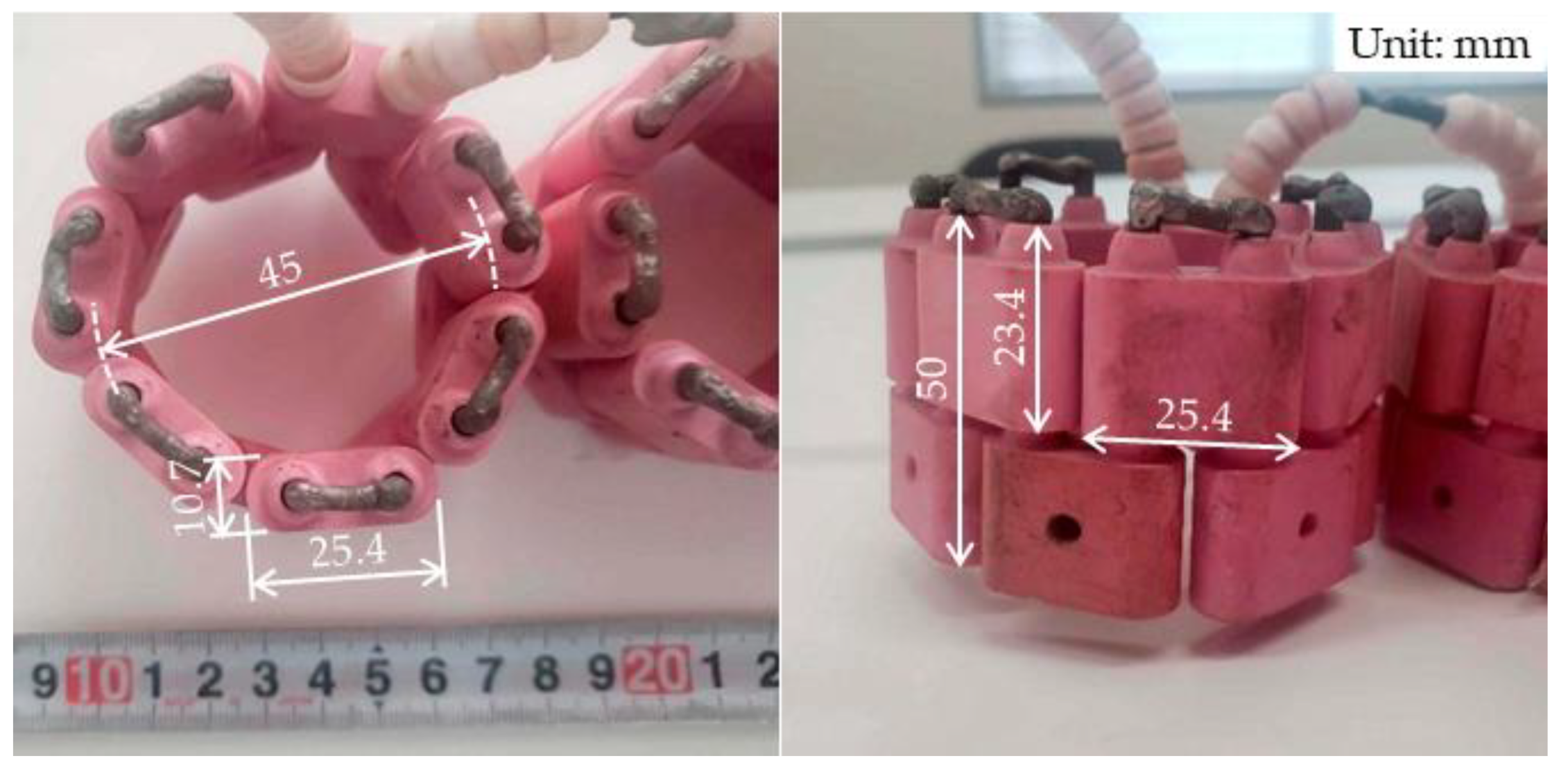
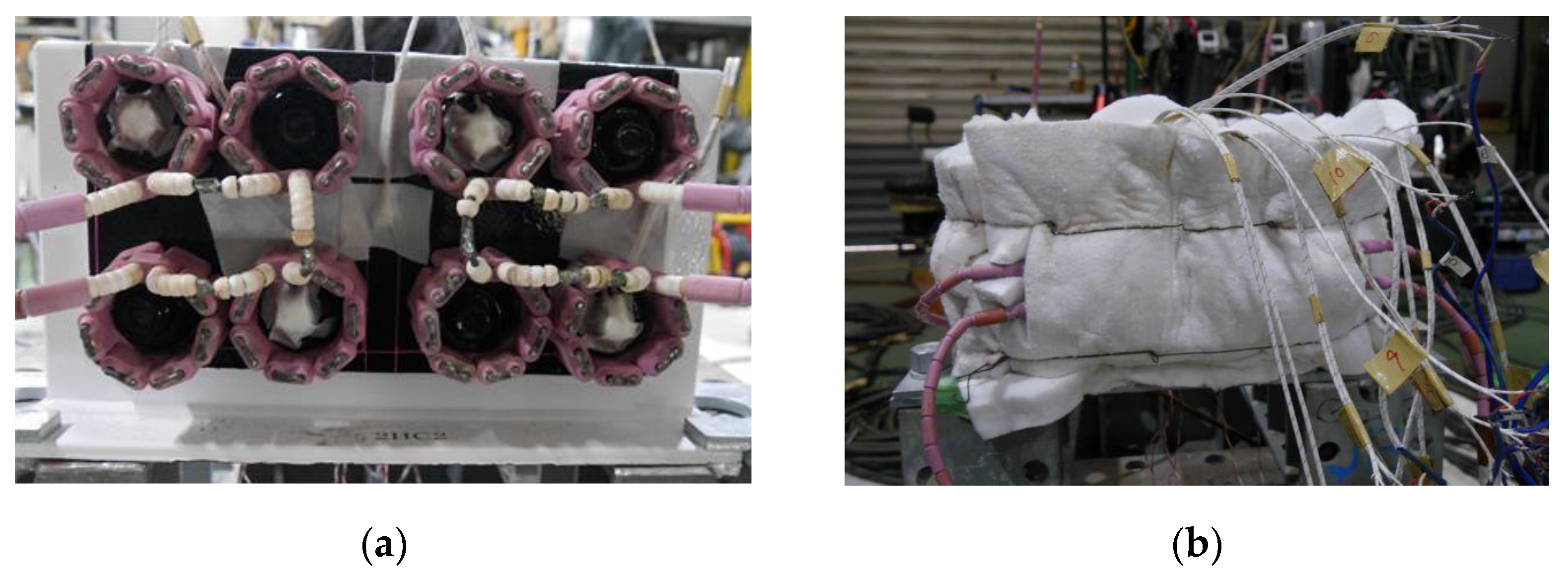
3.1. Device for Heating of Bolted Joints

Figure 2 shows the assembly of the ceramic heater for surrounding the nut in a ring shape. The ceramic pieces of 25.4 mm wideth, 23.4 mm hight, and 10.7 mm thickness were assembled to fit the nut of 32 mm wideth and 22 mm hight. The inner diameter and the height of the assembled heater were around 45 mm and 50 mm, respectively. The Ni-Cr electric wire with the diameter of 3.5 mm was covered by the ceramic pieces. The electric resistance of the wire was 0.11 Ω/m. The electric power of the heater was 0.2 kW per ring.
Figure 3a shows the heating device for the paint coating removal of bolted joints. The ceramic heater was assembled so that it surrounded each nut. The specimen and the heater were covered by thermal insulation material, as shown in Figure 3b. Figure 4 shows the positions of thermocouples. The thermocouples from TC1 to TC8 were attached to the tip of each bolt shaft. The thermocouples from TC9 to TC11 were attached to both surfaces of the cover plates. The thermocouple of TC3 was used for controlling the heat input and monitoring the temperature.
One previous research showed that the glass transformation temperature (Tg) of the fire-resistant alkyd resin for the paint coating was around 163 °C [17]. Another study reported that the alkyd resin coating for the mild steel was stable under the temperature 170 °C [18]. When the temperature was higher than this value, there was considerable mass loss by the base resin degradation. Therefore, the paint coating with the alkyd resin for the specimens in this study was estimated to be softened and prone to be removed by heating to 200 °C. To suppress the influence of the heating on the bolt axial force, the target temperature of the paint coating removal was set as 200 °C in this study. The target temperature was also determined by considering the reports that there was no change in the mechanical properties and shear strengths of the high-strength steel bolts after being subjected to heating up to 300 °C [19]. The heating was stopped when the temperature of TC3 reached 200 °C. To ensure the accurate control of temperature, the heating time was set as around 1800 s based on previously performed trial experiments. The actual heating time was 1680 s for Specimen No.1 and 1950 s for Specimen No.2.

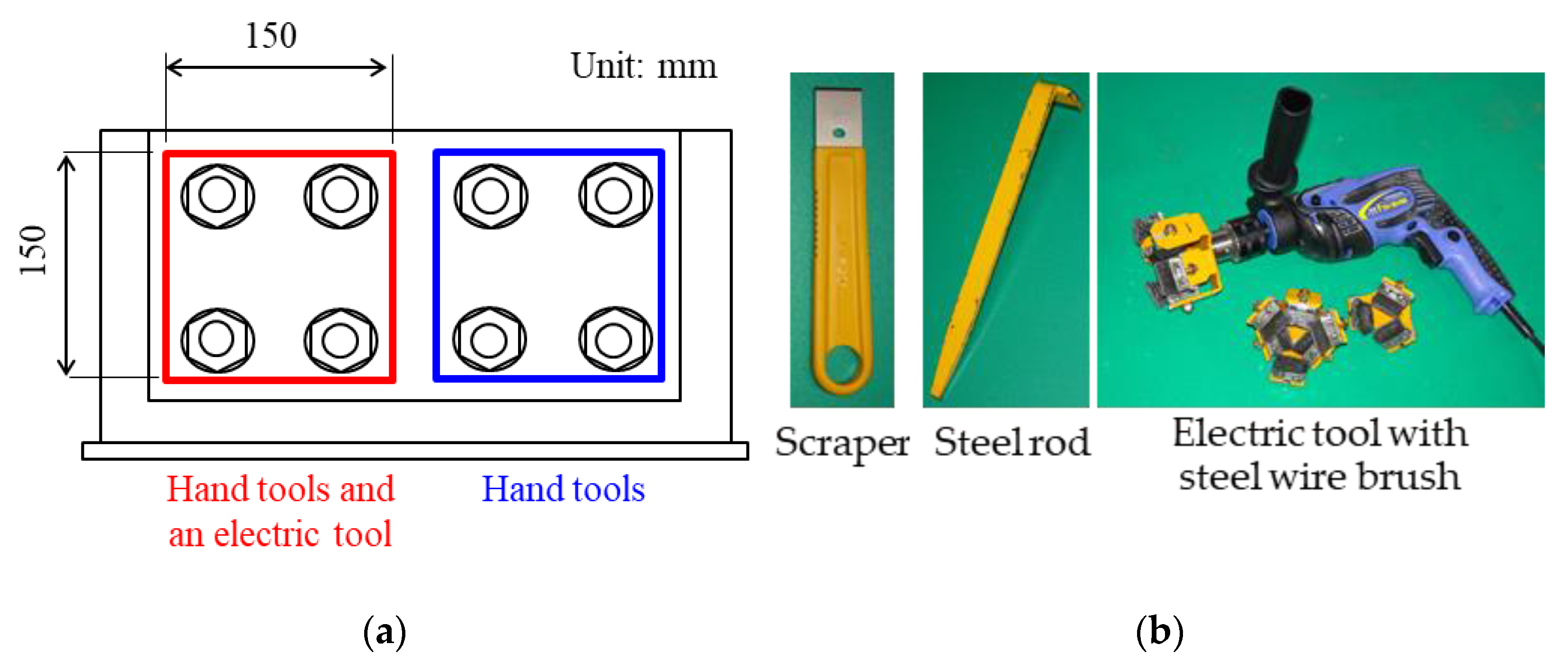
3.2. Paint Coating Removal

After reaching the target temperature of 200 °C, the paint coating on the specimens was removed using hand tools such as a scraper and a steel rod. Figure 5a shows the areas of paint coating removal. The paint coating of the right sides of the specimen including four bolts was removed by using these hand tools. The time for paint coating removal work by the hand tools was 240 s. The paint coating of the left side of the specimen was removed by the hand tools as well as the right side by 240 s. After that, the paint coating of the left side of the specimen was removed by an electric brushing tool with steel wire. Figure 5b shows the tools of paint coating removal work. The electric wire brush was a general commercial product. The wire brush was connected to an electric hand drill with the power consumption of around 700 W. It was recommended that the rotation speed is adjusted to no more than 600 rpm when used for the paint coating removal. The brushing time was roughly 30 s per nut.

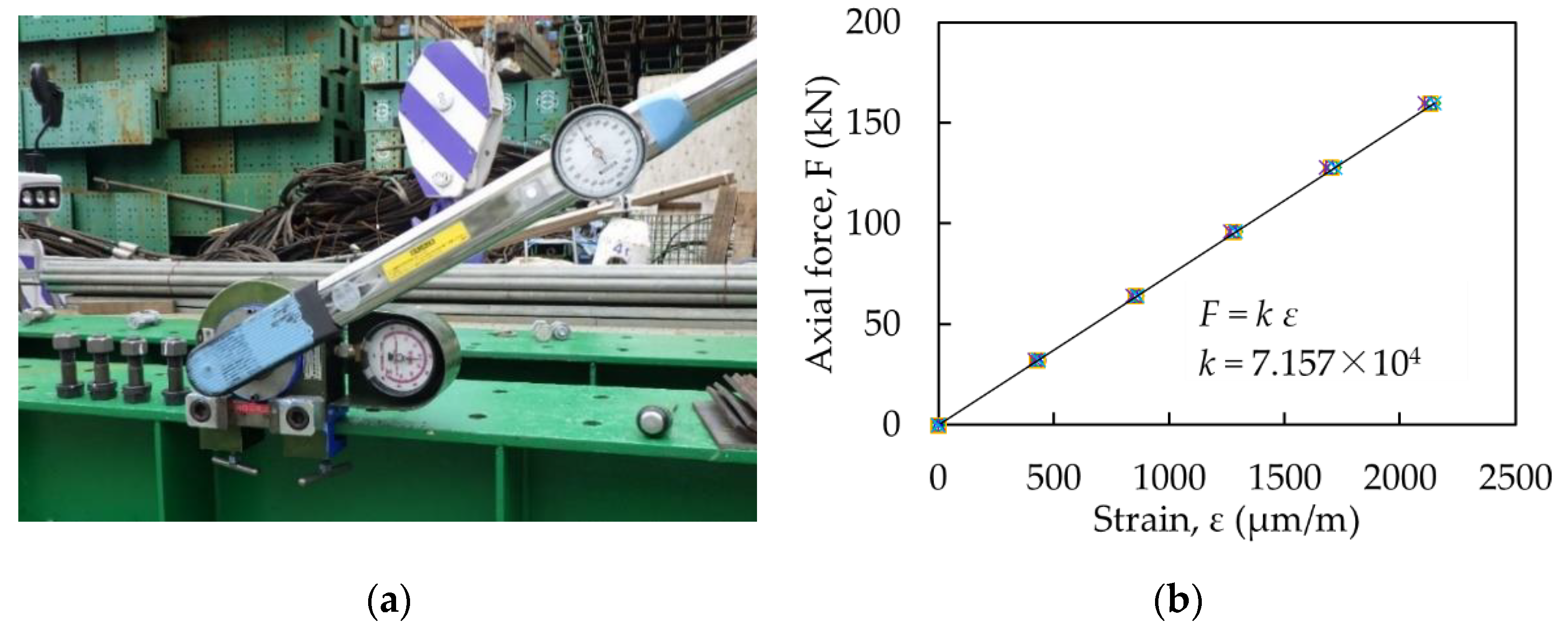
3.3. Strain Measurement of Bolts

For measuring the change in axial force during heating, strain gauges were attached to the surfaces of the bolt axes. Figure 6 shows the process of attaching the strain gauges. Two holes with a diameter of 3 mm were drilled into the bolt head. The lead wires of strain gauges were inserted into the holes. The strain gauges were attached to the position 12.5 mm away from the lower surface of the bolt head. Two strain gauges were attached on three bolts (#1, #3, and #6) per specimen.
The axial forces of the bolts were estimated by using a calibration coefficient previously obtained. The relationship between the axial force and the strain was obtained using five bolts. Figure 7a shows the appearance of the calibration experiment. Figure 7b shows the results of the calibration experiment. The slope of the relationship between the axial force and the strain corresponds to the calibration coefficient, which is 7.517 × 10⁴. The change in axial force during the heating experiment was obtained by multiplying this coefficient to the measured strain value.

4. Results and Discussions

4.1. Temperature Histories

Figure 8 shows the temperature histories during the heating (Figure 8a: Specimen No.1, Figure 8b: Specimen No.2). Because the tendencies of temperature histories of similar positions (TC1 to TC4, TC5 to TC8, TC10 and TC11) were almost the same with each other, only the temperature histories of TC2 (the upper bolt), TC6 (the lower bolt), TC9 (the cover plate of heated side), and TC10 (the cover plate of not heated side) are shown as representatives.
The temperature of TC2 could be accurately controlled. The maximum temperatures of TC2 in specimens No.1 and No.2 were 216 °C and 212 °C, respectively. They were within 10% of the target value. The temperatures of TC6 in specimens No.1 and No.2 were lower by 30 °C than those of TC2 because the heat was transferred to the frame for fixing the specimens. The temperatures of TC9 and TC10 attached to the cover plates were around 170 °C.

4.2. Degree of Paint Coating Removal

Figure 9a shows the appearance of the specimen being heated. Although some water vapor was generated when the temperature reached around 100 °C, substantial fumes and gas did not arise from the heated specimens even in the target temperature state. Figure 9b shows the appearance of the specimen when the thermal insulation and the ceramic heater were detached from the specimen after reaching the target temperature. The blisters of the paint coating were locally observed. Then, the paint coating was removed by the hand tools and the electric tool. The electric tool generated minor noise because the steel wire brush was stable under the recommended conditions and did not create a hitting sound with adjacent nuts.
Figure 10 shows the appearance of the specimens after the paint coating removal. The paint coating of bolts could be removed by heating and using hand tools. However, the paint coating at the boundaries between the nut and washer or between the washer and cover plates was difficult to remove using the hand tools (right side). When using the electric brushing tool in addition to the hand tools, more of the paint coating around these parts could be removed (left side). The steel substrate at this part was exposed due to the brushing.

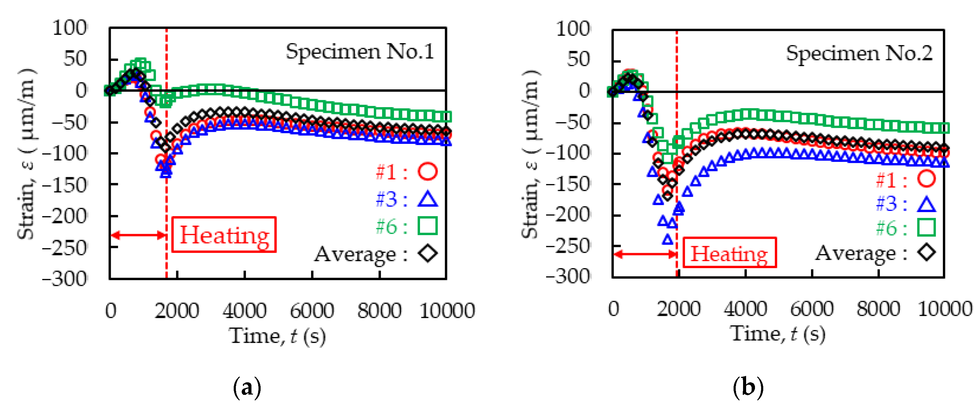
4.3. Behaviour of Axial Strain of Bolts

Figure 11 shows the behaviours of axial strains measured by three bolts in each specimen (Figure 11a: Specimen No.1, Figure 11b: Specimen No.2). In this experiment, the nuts were surrounded by the heater and heated. The thermal expansion of nuts elongated the bolts. Therefore, the strain increases in the bolts were observed at 750 s in Specimen No.1 and 450 s in Specimen No.2 from the start of heating. The maximum positive strains, on average, were 28.8 μm/m (standard deviation: 10.7 μm/m) in Specimen No.1 and 22.3 μm/m (standard deviation: 7.8 μm/m) in Specimen No.2. After that, the strain was reduced and changed to a negative value by the end of the heating. The minimum negative strains, on average, were −89.5 μm/m (standard deviation: 62.1 μm/m) in Specimen No.1 and −168.2 μm/m (standard deviation: 65.5 μm/m) in Specimen No.2. The high tensile axial forces originally were installed to the bolts. The additional expansions of bolts due to the heating of nuts might cause the yielding of the bolts in the former heating stage at 750 s in Specimen No.1 and 450 s in Specimen No.2. At that time, the temperatures of the bolt tips measured by the thermocouples TC2 and TC6 were around 80 °C in Specimen No.1 and 46 °C in Specimen No.2, respectively. The thermal strain, εT, of the steel material can be calculated by the following Equation (1).
εT = αΔT
where εT is the thermal strain, α (1/°C) is the linear expansion coefficient (in the case of a general steel material, α = 1.2 × 10⁻⁵), and ΔT (°C) is the temperature change. When using the initial temperature of the bolts as 25 and the temperatures of the bolt tips at the time of 750 s in Specimen No.1 (80 °C) and 450 s in Specimen No.2 (80 °C), the thermal strains might be 660 μm/m in Specimen No.1 and 252 μm/m in Specimen No.2, respectively. Even though the temperatures of the nuts were not measured directly, they might be close to the temperatures at the bolt tips (TC2 and TC6). Then, the thermal strain of the nuts might be larger than the measured strain values of the bolt axes. This means that the thermal expansion of the bolt might be restrained and the bolts may not be expanded freely in the former heating stage. At the same time, the base plates and the cover plates were also expanded in the thickness direction by the heating. The expansions might be restrained by the bolts and the nuts. The high tensile axial forces of bolts and the expansions of the plates might cause the yielding of cover plates around the bolt holes. The yielding of cover plates around the bolt holes might release the elastic deformations of bolts. Therefore, the decrease in strain might occur in the later heating stage.
In the cooling stage, the deformations of the nuts, bolts, and cover plates might reduce. However, the bolts were not recovered to their original lengths because of the plastic deformation in the heating stage. As a result, the negative strain values might remain. The values of the remaining strains, on average, were −63.3 μm/m (standard deviation: 19.4 μm/m) in Specimen No.1 and −89.5 μm/m (standard deviation: 28.2 μm/m) in Specimen No.2.

4.4. Estimation of Axial Forces of Bolts

It is known that the axial force of the bolt directly influences the slip resistance of the bolted joint. ISO10721 (Steel structures—Part 1: Materials and design) shows the slip resistance of the bolted joints, which is proportional to the preloading force of the bolt (the axial force) [20]. Previous research reported that not only the slip resistance but also the fretting fatigue resistance of the bolt hole might be influenced by the magnitude of the pre-tension (the axial force) of the bolt [21]. It can be said that the reduction in axial force strongly influences the basic structural performance of the bolted joints. Therefore, the effect of the sectional damage of the nut assuming the corrosion on the clamping force of the bolt connections was examined [22]. The image-based or audio-based inspection technologies for the bolt-loosening were investigated [23,24]. These references show the importance of the reduction in the axial force of the bolts in the structural performance of the steel bridges.
Table 3 shows the estimated axial forces of bolts from the values of strains. The axial forces after tightening were estimated by multiplying the calibration coefficient by the strain values obtained when the bolts were tightened. The reduction in the axial forces of bolts due to heating was also estimated by multiplying the calibration coefficient by the changes in the strain values after heating. The reduction in the axial forces of bolts was 2.6% of the initially tightened axial forces, on average. It is known that the reduction in the axial forces of bolts generally occurs due to relaxation of bolts. Considering this reduction in axial forces and a certain safety margin, the target axial forces when initially tightened is specified as 10% higher than the designed axial forces in Japan and Korea [25]. The reduction in axial forces of the bolts by the heating for paint coating removal was relatively smaller than that by the relaxation of bolts. Although the influence of the heating on the bolt axial force was experimentally examined, a more detailed investigation will be numerically and analytically performed in future work.

4.5. Power Consumption Estimation and a Proposal of Work Procedure for Paint Coating Removal

The ceramic heater used in this study had the electric power of 0.2 kW per ring. Assuming the heating time of 1800 s, which was the original target value, the power consumption for heating a nut might be estimated as 0.1 kWh. The electric tool used for brushing the nut in this study consumed 700 W. The brushing time per nut was 30 s. The power consumption for brushing a nut might be estimated as 0.006 kWh.
The ceramic heaters used in this study were assembled so that the nuts were surrounded one by one. The ring-shaped heater units were connected to each other. Therefore, the number of the heater units might be selected as matching the number of the nuts or the bolts in the actual bolted joints in the steel bridges. However, it may be difficult to heat many bolts and nuts in one joint simultaneously because the section will be heated. Our previous research [14] recommended that bolts and nuts in some rows are heated at one cycle. After heating the first group, the other groups of bolts and nuts can be heated. During the second cycle of heating, the paint coating removal work for the first group, which has already been heated, can be performed. By repeating this procedure, the waiting time for the heating can be utilised. The actual working procedure should be considered by the number of the bolts and the nuts in the joints.

5. Conclusions

A series of experiments were conducted for proposing a paint coating removal method with heating by a ceramic heater for bolted joints in steel bridges. Based on the experimental results, the influence of the heating on the bolt axial force was examined. The main results obtained are as follows.
(1)
The accuracy of temperature control by the heating device was confirmed. The bolted joints specimens could be heated to the target temperature of 200 °C without extreme overheating. After the heating, the paint coating around the bolts and the nuts could be removed by using hand tools and an electric tool with a wire brush.
(2)
The reduction in the axial force of the bolts was examined by monitoring the change in strain during the heating process. The heating of the nuts expanded the bolts in the former stage and the bolts might be yielded. The thermal expansion of the base plates and the cover plates were restrained by the bolts in the later heating stage; therefore, the plates around the bolt holes might be yielded. These yielding might cause the reduction in the axial force of the bolts.
(3)
The reduction in the axial force of the bolts was 2.6% of the originally installed axial force, on average. It was within the safety margin in the design of bolted joints for steel bridges.
In this study, the influence of the heating for the paint coating removal on the bolt axial force was experimentally examined. The mechanism of the change in the bolt axial force was discussed. However, a more detailed investigation will be numerically and analytically performed in future work.

Author Contributions

Conceptualisation, M.H.; methodology, T.N., T.F. and M.H.; experiment, S.K. and T.N.; validation, T.N. and M.H.; writing—original draft preparation, T.N.; writing—review and editing, M.H. All authors have read and agreed to the published version of the manuscript.

Funding

This research was funded by Rent All Scholarship Foundation in 2020.

Institutional Review Board Statement

Not applicable.

Informed Consent Statement

Not applicable.

Data Availability Statement

Not applicable.

Acknowledgments

Engineers of JEMIX Co., Ltd. supported the experiment by using the ceramic heater. The authors greatly appreciate their support.

Conflicts of Interest

The authors declare no conflict of interest.

References

  1. Kage, I.; Matsui, K.; Kawabata, F. Minimum maintenance steel plates and their application technologies for bridge—Life cycle cost reduction technologies with environmental safeguards for preventing social infrastructure assets. JFE Tech. Rep. 2005, 5, 37–44. [Google Scholar]
  2. Kreisolva, K.; Geiplova, H. Evaluation of corrosion protection of steel bridges. Procedia Eng. 2012, 40, 229–234. [Google Scholar] [CrossRef] [Green Version]
  3. Kline, E.S. Steel bridges: Corrosion protection for 100 years. J. Prot. Coat. Linings 2008, 25, 20–31. [Google Scholar]
  4. Itoh, Y.; Hirohata, M.; Hosoi, A.; Sugiura, Y. Anticorrosive performance of repair painting as remedy for deterioration in metallised steel. Corros. Eng. Sci. Technol. 2013, 48, 537–551. [Google Scholar] [CrossRef]
  5. Hopwood, T., II; Oberst, C.M. The Removal of Lead-Based Paint from Steel Bridges. In Research Report; Kentucky Transportation Center: Lexington, KY, USA, 1993; pp. 20–23. [Google Scholar]
  6. Li, X.; Wang, H.; Yu, W.; Wang, L.; Wang, D.; Cheng, H.; Wang, L. Laser paint stripping strategy in engineering application: A systematic review. Opt. Int. J. Light Electron Opt. 2021, 241, 167036. [Google Scholar] [CrossRef]
  7. Madhukar, Y.K.; Mullick, S.; Nath, A.K. Development of a water-jet assisted laser paint removal process. Appl. Surf. Sci. 2013, 286, 192–205. [Google Scholar] [CrossRef]
  8. RPR Technologies. Available online: https://www.rprtech.com/ (accessed on 16 September 2021).
  9. Nakamura, M.; Hirohata, M.; Inoue, K.; Konishi, H. Applicability of Induction Heating on Paint Coating Removal of Steel Bridge Member. In Proceedings of the 9th International Symposium on Steel Structures, Jeju, Korea, 1–4 November 2017; pp. 401–403. [Google Scholar]
  10. Konishi, H.; Suzuki, N.; Tanaka, M.; Sameshima, C.; Nishitani, T.; Hirohata, M. Application of induction heating for removal coating in Kyoda steel bridges. Bridge Found. Eng. 2017, 7, 14–20. (In Japanese) [Google Scholar]
  11. Konishi, H.; Ihaya, T.; Fukushima, N.; Matsui, T.; Hayashi, M.; Hirohata, M. Field test of coating removal by induction heating in Ichikawa bridge. Bridge Found. Eng. 2020, 6, 18–23. (In Japanese) [Google Scholar]
  12. Hirohata, M. Effect of post weld heat treatment on steel plate deck with trough rib by portable heat source. Weld. World 2017, 61, 1225–1235. [Google Scholar] [CrossRef]
  13. Aung, M.P.; Hirohata, M. Numerical study on post-weld heat treatment of non-stiffened welded box section member. Int. J. Steel Struct. 2019, 19, 1521–1533. [Google Scholar] [CrossRef]
  14. Hirohata, M.; Toyoshima, D.; Konishi, H. Paint coating removal technique for bolted joints by portable heating device. In Proceedings of the 10th International Symposium on Steel Structures, Jeju, Korea, 13–16 November 2019; p. O-022. [Google Scholar]
  15. Uno, N.; Nagata, M.; Kanisawa, H.; Azuma, K. Super-high-strength bolt, “SHTB®”. Nippon. Steel Tech. Rep. 2008, 97, 95–104. [Google Scholar]
  16. Kim, I.T.; Itoh, Y. Accelerated exposure tests as evaluation tool for estimating life of organic coatings on steel bridges. Corros. Eng. Sci. Technol. 2007, 42, 242–252. [Google Scholar] [CrossRef]
  17. Gündüz, G.; Kisakürek, D.; Kayadan, S. Flame retardant alkyd paint. Polym. Degrad. Stab. 1999, 64, 501–504. [Google Scholar] [CrossRef]
  18. Gonçalves, G.S.; Baldissera, A.F.; Rodrigues, L.F., Jr.; Martini, E.M.A.; Ferreira, C.A. Alkyd coatings containing polyanilines for corrosion protection of mild steel. Synth. Met. 2011, 161, 313–323. [Google Scholar] [CrossRef] [Green Version]
  19. Kodur, V.; Yahyai, M.; Rezaeian, A.; Eslami, M.; Poormohamadi, A. Residual mechanical properties of high strength steel bolts subjected to heating-cooling cycle. J. Constr. Steel Res. 2017, 131, 122–131. [Google Scholar] [CrossRef]
  20. International Organization for Standardization. ISO10721-1 Steel Structures—Part 1: Materials and Design; International Organization for Standardization: Geneva, Switzerland, 1997; pp. 75–76. [Google Scholar]
  21. Jiménez-Peña, C.; Talemi, R.H.; Rossi, B.; Debruyne, D. Investigations on the fretting fatigue failure mechanism of bolted joints in high strength steel subjected to different levels of pre-tension. Tribol. Int. 2017, 108, 128–140. [Google Scholar] [CrossRef]
  22. Ahn, J.-H.; You, J.M.; Huh, J.; Kim, I.-T.; Jeong, Y.-S. Residual clamping force of bolt connections caused by sectional damage of nuts. J. Constr. Steel Res. 2017, 136, 204–214. [Google Scholar] [CrossRef]
  23. Park, J.H.; Kim, T.H.; Kim, J.T. Image-based bolt loosening detection technique of bolt joint in steel bridge. In Proceedings of the 6th International Conference on Advances in Experimental Structural Engineering, 11th International Workshop on Advanced Smart Materials and Smart Structures Technology, Urbana, IL, USA, 1–2 August 2015. [Google Scholar]
  24. Zhang, Y.; Zhao, X.; Sun, X.; Su, W.; Xue, Z. Bolt loosening detection based on audio classification. Adv. Struct. Eng. 2019, 22, 2882–2891. [Google Scholar] [CrossRef]
  25. Nah, H.-S.; Lee, H.-J.; Kim, K.-S.; Kim, J.-H.; Kim, W.-B. Evaluating relaxation of high-strength bolts by parameters of slip faying surfaces of bolted connections. Int. J. Steel Struct. 2010, 10, 295–303. [Google Scholar] [CrossRef]
Figure 1. Shape and dimension of the specimen.
Applmech 02 00042 g001
Figure 2. Assembly of the ceramic heater.
Applmech 02 00042 g002
Figure 3. (a) Ceramic heater surrounding nuts; (b) thermal insulation material covering the specimen.
Applmech 02 00042 g003
Figure 4. Positions of thermocouples.
Applmech 02 00042 g004
Figure 5. (a) Areas of paint coating removal work; (b) tools for paint coating removal.
Applmech 02 00042 g005
Figure 6. Process and position of a strain gauge in a bolt.
Applmech 02 00042 g006
Figure 7. (a) Appearance of calibration experiment; (b) relationship between strain and axial force of the bolts.
Applmech 02 00042 g007
Figure 8. (a) Temperature history of Specimen No.1; (b) temperature history of Specimen No.2.
Applmech 02 00042 g008
Figure 9. (a) The specimen being heated; (b) the specimen just after detaching thermal insulation.
Applmech 02 00042 g009
Figure 10. Appearance of the specimen after paint coating removal.
Applmech 02 00042 g010
Figure 11. (a) Strain change of Specimen No.1; (b) strain change of Specimen No.2.
Applmech 02 00042 g011
Table 1. Mechanical properties of the materials.
MaterialYield Strength
(N/mm2)
Tensile Strength
(N/mm2)
Elongation
(%)
Plate: SS40032344033
Bolt (rot 1): F10T1022107620
Bolt (rot 2): F10T1023107720
Table 2. Specifications for A-type paint coating system (Bolted joints).
ProcessPaint TypeThickness (μm)
Surface preparationGrinding, ISO St3-
UndercoatAnti-corrosion paint without Pb and Cr35 × 3 layers
Middle coatLong oil alkyd resin30
TopcoatLong oil alkyd resin25
Table 3. Reduction in bolt axial force.
Specimen No.1Specimen No.2Average
(Standard Deviation)
#1#3#6#1#3#6
Initial axial force (kN)241232221217234243231 (10.5)
Axial force reduction (kN)5.65.73.28.09.24.76.1 (2.2)
Reduction percentage (%)2.32.41.43.63.91.92.6 (0.97)
Publisher’s Note: MDPI stays neutral with regard to jurisdictional claims in published maps and institutional affiliations.

