Abstract
In previous studies, a smeared truss model based on a refinement of the rotating-angle softened truss model (RA-STM) was proposed to predict the full response of structural concrete panel elements under in-plane monotonic loading. This model, called the “efficient RA-STM procedure”, was validated against the experimental results of reinforced and prestressed concrete panels, steel fiber concrete panels, and reinforced concrete panels externally strengthened with fiber-reinforced polymers. The model incorporates equilibrium and compatibility equations, as well as appropriate smeared constitutive laws of the materials. Besides, it incorporates an efficient algorithm for the calculation procedure to compute the solution points without using the classical trial-and-error technique, providing high numerical efficiency and stability. In this study, the efficient RA-STM procedure is adapted and checked against some experimental data related to reinforced concrete (RC) panels tested under in-plane cyclic shear until failure and found in the literature. Being a monotonic model, the predictions from the model are compared with the experimental envelopes of the hysteretic shear stress–shear strain loops. It is shown that the predictions for the shape (at least until the peak load is reached) and for key shear stresses (namely, cracking, yielding, and maximum shear stresses) of the envelope shear stress–shear strain curves are in reasonably good agreement with the experimental ones. From the obtained results, the efficient RA-STM procedure can be considered as a reliable model to predict some important features of the response of RC panels under cyclic shear, at least for a precheck analysis or predesign.
1. Introduction
Reinforced concrete (RC) wall-type structures, such as shear walls or deep beams, and RC shell-type structures, such as containers or curved shell roofs, are widely designed and built all over the world. A rational way to analyze such structures is to consider that they result from the union of small two-dimensional (2D) RC membrane or panel elements under in-plane stresses. Then, rational and simplified models can be developed to study such RC panel elements before they are incorporated into more general models—for instance, in a finite element program—which allows analyzing the whole structure [1]. Such simplified models can also be used to check locally a critical zone of the structure as a complement to a more global analysis.
During the last three decades, several models to study RC panel elements were developed based on the smeared-crack concept. Such models are built in the form of a plain stress field (or, simply, plain truss) approach and have proven to be sufficiently reliable and easy to be implemented in a computer. These models satisfy Navier’s three principles for mechanics of materials, which are stress equilibrium, strain compatibility, and constitutive laws of materials. Both the stresses and strains are evaluated in a sufficiently wide zone in order to include the average influence of several cracks. Hence, smeared constitutive laws, experimentally calibrated and accounting for the existing biaxial stress state in the RC panel elements, must be incorporated. As a result, the obtained smeared truss models allow accounting for the nonlinear behaviors and interactions between each of the material components in the RC panel elements—namely, concrete in compression, concrete in tension, and steel (reinforcement) in tension. Below, a brief reference to some of the most important proposed smeared truss models is presented, which were mainly developed from studies performed in the University of Toronto and in the University of Houston, where special devices were specifically built (the so-called Shear Rig and Universal Panel Tester, respectively) to test structural concrete panels under controlled biaxial stress states.
Based on the experimental results obtained in the University of Toronto, Vecchio and Collins in 1981 [2] and 1982 [3] developed the Compression Field Theory (CFT) which idealizes the resistance mechanism as a nonlinear plain truss, where steel bars resist to axial tensile stresses and concrete resists to compressive stresses. In addition, it assumes that the angles of both the principal compressive stresses and strains in concrete coincide, alongside the angle of cracks, which coincides with the angle of the principal compressive stresses. Since this angle evolves during the loading history due to internal redistributions, the model assumes that the crack rotates until failure occurs. The CFT proved its efficiency to model the shear behavior of RC panels after cracking and up to failure. Later, Vecchio and Collins in 1986 [4] extended the model to incorporate the tensile stresses in concrete, which can significantly increase the post-cracking stiffness of the RC panels, as experimentally observed. The new model was called Modified Compression Field Theory (MCFT). Variants of the models from Vecchio and Collins were developed and proposed during the later years [5,6,7,8,9].
Based on several additional experimental data from the RC panels tested at the University of Houston, Prof. Thomas Hsu and collaborators successively developed and refined alternative smeared truss models. The first major innovation was to propose and incorporate in the models new and calibrated smeared constitutive stress ()–strain () laws for the materials [10,11]. The first proposed model was the so-called Rotating-Angle Softened Truss Model (RA-STM) [12], which was extended later so that it incorporates high-strength concrete panels [13]. The RA-STM neglects the contribution of concrete in shear, because, for simplicity, both equilibrium and compatibility equations are stated in a reference frame, which coincides with the rotating principal directions of internal stresses in concrete. To incorporate the referred contribution, a new fixed reference frame was considered to state the equations, which coincided with the constant principal directions of the external stresses applied to the RC panel. In addition, new experimental data allowed to calibrate a smeared shear stress ()–shear strain () relationship for concrete in shear to be incorporated in the model. The new model was called the Fixed-Angle Softened Truss Model (FA-STM) [14,15]. Later, aiming to improve the prediction of the post-peak response of the RC panels, and based on additional experimental results, the Poisson’s effect in the cracking state was incorporated into the model through new calibrated parameters called Hsu/Zhu ratios [16,17,18]. A new model was proposed, called the Softened Membrane Model (SMM). Variants of the models with fixed reference frames were also developed and proposed by other authors [6,19].
Finally, new experimental results on RC panels under cyclic shear, perfomed at the University of Toronto (where three RC panels were tested) and at the University of Houston (where twelve RC panels were tested), allowed to calibrate smeared cyclic constitutive laws for the materials and to refine the Hsu/Zhu ratios [20,21,22,23]. This allowed extending both the MCFT and the SMM (for this latter, the new model was called the Cyclic Softened Membrane Model (CSMM)) to RC panels under cyclic shear [20,22,24]. It should be also noted that, before the referred studies, experimental tests with five RC panels under cyclic shear were carried on at Kajima Corporation in Japan [25] with the sole objective of finding the constitutive laws of concrete and steel. From all the three facilities where RC panels were tested under cyclic shear, the Universal Panel Tester from the University of Houston was the only one that incorporated a servo control system for strain-controlled tests, allowing to register the post yield hysteretic loops of the RC panels with much more accuracy and for a longer shear strain range [26]. For this reason, the experimental results and proposals for the smeared cyclic constitutive laws for the materials from the University of Houston can be considered more accurate [21,22,23]. Finally, it should also be referred to that a recent alternative smeared truss model for RC panels under cyclic shear was proposed as well, the Fixed Strut Angle Model (FSAM), which incorporates additional friction-based constitutive law to compute the shear stresses along crack surfaces [27].
In spite of how some of the referred cyclic smeared truss models have been shown to predict well the global hysteretic response of RC panels under cyclic shear, such as the the CSMM and FSAM, they are not easy to implement, because they incorporate smeared cyclic constitutive laws for the materials. Such laws have a complex development to account for the possibility of several loading–unloading cycles at different points and, also, for the damage of concrete during the loading history. For a precheck analysis or a predesign, it is usually sufficient to compute the envelope of the hysteretic behavioral curves, such as for the – loops of the RC panels under cyclic shear. For such a purpose, previous studies have showed that the main features of such envelope curves are reasonably well-depicted by using a monotonic smeared truss model—for instance, the MCFT—at least until the peak load is reached [20,25]. This is also true for the other referred monotonic models, such as the RA-STM, the FA-STM, and the SMM. Hence, the goal of this study is to explore the use of a simpler monotonic smeared truss model to predict the main features of the envelope – curves of RC panels under cyclic shear.
Among the referred monotonic smeared truss models, the RA-STM is the one with the simplest calculation procedure. This model was shown to be sufficiently reliable to predict the full response of RC panels under monotonic shear [12,13]. These features of the model justify why it continues to be used as a base model, including being extended to analyze different structural members than RC panels [28,29,30,31]. In addition, in the last years, the RA-STM has also been extended and refined in order to provide better predictions and, also, to increase the efficiency and stability of the numerical calculation procedure [18,32,33,34,35]. In fact, the calculation procedure of the original RA-STM, as for the other previously referred smeared truss models, is based on a trial-and-error technique, which may require a large calculation effort and lose numerical efficiency because of the large number of initial estimates that are required to start the calculations. To solve these drawbacks, the RA-STM was recently reformulated as a system of nonlinear equations with constraints that are solved with an optimization algorithm instead of using the trial-and-error technique [34]. The new version of the RA-STM was called the “efficient RA-STM procedure” and was shown to be numerically very efficient and stable, as well as reliable, to predict the full response of RC panels under monotonic shear.
To the best of the authors’ knowledge, no previous study extensively checked the applicability of a simpler monotonic smeared truss model to predict the main features of the response of RC panels under cyclic shear. Hence, in this study, the monotonic efficient RA-STM procedure previousy proposed by the corresponding author and verified for RC panels under monotonic shear is used to predict the envelope – curves of RC panels under cyclic shear. The predictions from the model are checked against the experimental envelope – curves from twelve RC panels under cyclic shear tested at the University of Houston. From the obtained results, it is shown that the model is able to predict reasonably well the shape and some important features, such as key shear stresses, of the envelope – curves.
2. Efficient RA-STM Procedure
The details of the model used in this study, the efficient RA-STM procedure for RC panels under monotonic shear, can be found in a previous article [34]—namely, the hypothesis, the derivation of the equations, and the description of the efficient numerical calculation procedure to compute the solution points. However, for the sake of the readers, this section summarizes both the fundamental equations and the numerical solution procedure of the model. Since the monotonic character of the model is preserved, the equations and the numerical solution procedure remain unchanged. However, since the model is applied here to RC panels under cyclic shear, a new damage coefficient is introduced in the smeared constitutive law for concrete in compression (as explained in Section 2.2.1). The relevance of this modification is discussed in detail in Section 3.
2.1. Equilibrium and Compatibility Equations
In Figure 1, an RC plate element under in-plane normal stresses in the longitudinal () and transverse () directions and shear stresses () are illustrated. The L-T reference frame coincides with the direction of the longitudinal and transverse reinforcements. For the analysis, the RC panel element can be viewed as the superposition of a concrete element with in-plane stresses , and and a steel grid element (steel reinforcing bars) with normal tensile stresses and . In Figure 1, and stand for the normal stress in steel reinforcement and for the reinforcement ratio, respectively.
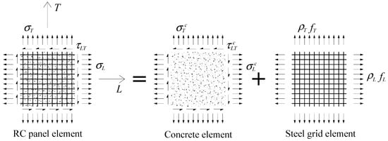
Figure 1.
Reinforced concrete (RC) plate element under in-plane stresses.
From Figure 1, the following matrix equilibrium equation for stresses can be stated in the L-T reference frame:
Figure 2 illustrates the principal stresses ( and ) applied in the concrete element and the variable angle between the L-T and D-R reference frames. From Figure 2, the in-plane stresses in the L-T reference frame can be related in a matrix form with the principal stresses and the variable angle as follows:
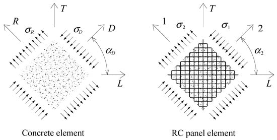
Figure 2.
Principal directions and principal stresses.
By using a similar transformation law, the average normal and shear strain components in the L-T reference frame (, and , respectively) can be related in a matrix form with the principal strains ( and ) and the variable angle as follows:
In addition, the following invariant equation can be derived from Mohr’s circle for strains:
Equations (3) and (4) are the compatibility equations.
2.2. Smeared Constitutive Laws
The smeared constitutive laws for the materials used in this study—namely, for concrete in compression, concrete in tension, and embedded steel reinforcement in tension—are basically the same ones used and justified in a previous study for RC panels under monotonic shear [34]. This option can be considered valid, because this study solely aims to compute the envelope – curves of RC panels under cyclic shear. As discussed by Mansour and Hsu in 2005 [24], previous studies on concrete and steel specimens under uniaxial cyclic loading showed that the hysteretic loops of the – curves produced an envelope curve practically identical to the curve obtained under monotonic loading. This was also experimentally observed by Mansour et al. in 2001 [21] for the envelope curves obtained for cyclic loading—namely, to validate the monotonic curves proposed by Belarbi and Hsu in 1994 [10] and 1995 [11]—and, also, the softening coefficient for concrete in compression proposed by Zhang and Hsu in 1998 [13].
2.2.1. Concrete
For concrete in compression, the smeared softened – relationship proposed by Belarbi and Hsu in 1995 [11] (Equation (5), see Figure 3), incorporating the softening coefficient from Zhang and Hsu in 1998 [13] (refined latter by Zhu et al. in 2001 [18]), is used. As discussed by Mansour and Hsu in 2005 [24], the constitutive law for concrete in compression must consider the damage caused by the history of reversal tensile and compressive stress normal to the compression direction being analyzed. This can be done by incorporating the damage coefficient from Equation (6), which was proposed and calibrated by the referred authors based on their experimental results. In this study, is applied to the smeared monotonic curves (Equation (5)).
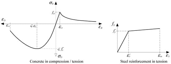
Figure 3.
Smeared constitutive laws.
In the previous equations, the meaning of the new parameters is the following: is the uniaxial cylinder compressive strength of concrete, is the strain corresponding to the peak cylinder stress (), is the ratio of the transverse to the longitudinal tensile strength of steel reinforcements, and () is the yielding stress for the longitudinal (transverse) reinforcement. To compute the damage coefficient , Mansour and Hsu [24] defined as the maximum compression strain normal to the compression direction under consideration that occurred in the previous loading cycle and considered to be constant and equal to 0.4 (a value that showed to best fit the test results of the cyclic – curves [22]). For this study, some considerations regarding the damage coefficient are stated in Section 3.
For concrete in tension, the smeared, softened – relationship proposed by Belarbi and Hsu in 1994 [10] (Equation (10), see Figure 3) was used in this study.
is the You’s Modulus for concrete, and is the tensile strain corresponding to the peak stress (concrete tensile strength). and can be computed from the correlation with by using codes’ rules. can be considered constant and equal to 0.00008 [10].
2.2.2. Steel Reinforcement
To model the behavior of steel bars in tension embedded in concrete, the smeared and bilinear – stiffened relationship proposed by Jeng and Hsu in 2009 [36] (Equation (11), see Figure 3), which constitutes a simplification of the nonlinear relationship from Belarbi and Hsu in 1994 [10], is used.
In the previous equations, and are the average tensile stress and strain in the steel reinforcement, respectively, is the yielding stress, and is Young’s modulus for steel. The subscript “” must be replaced by “” and “” for the longitudinal and transverse steel reinforcements, respectively.
2.3. Efficient Solution Procedure
2.3.1. Equations for Proportional Loading
For proportional loading, the ratios of the applied in-plane stresses in the RC panel element are constant. This condition is incorporated through the proportionality coefficients (Equation (15)), (Equation (16)), and (Equation (17)). These coefficients relate the applied in-plane stresses in the L-T reference frame (, and , see Figure 1) with the applied principal tensile stress in the 1 and 2 reference frames (see Figure 2).
Substituting , and from Equations (15) to (17) into Equations (1) and (2) after some algebraic manipulations and considering the applied principal tensile stress in the RC panel element (see Figure 2) as the independent variable, a quadratic equation (Equation (18)) can be stated, with Equation (22) as the solution equation for [34].
From Mohr’s circle for stresses, can be related with the stresses in the L-T reference frame system as follows [34]:
2.3.2. Residual Function for the Initial Estimates
The average strains , , and are chosen to be the initial estimates to start the efficient RA-STM procedure. For this, additional algebraic manipulations to those that led to Equations (18) to (23) allow to write Equations (24)–(26) to compute the average strains as a function of the proportionality coefficients (, and ); the applied principal stress ; and the variable angle (see Figure 2) [34]. To obtain Equations (24)–(26), and for the early stage (first loading increment), the tensile concrete was neglected, and the materials were considered to behave in the linear and elastic stages so that Hooke’s law holds (, and ).
From Equation (3), the variable angle (Figure 2) can be written as a function of the average strains in both the L-T and R-D reference frames through Equation (27) [34].
From Equation (27), a nonlinear residual function () is stated (Equation (28)) where the average strains are defined from Equations (24) to (26). This residual function is set to zero (Equation (29)) and numerically solved for . The solution angle , the value which minimizes , is used to compute the initial estimates , , and by using Equations (24)–(26) again. Such values are used to start the efficient RA-STM procedure, as explained below.
2.3.3. Residual Functions for the Efficient RA-STM Procedure
In the efficient RA-STM procedure, the average strains and are chosen to be the primary variables. To numerically compute these variables, two nonlinear residual functions ( and defined in the matrix Equation (30)) were stated from additional algebraic manipulations involving the equations resulting from the substitution of Equations (15)–(17) into the equilibrium Equations (1) and (2) and, also, the equations relating the variable angle and the average strains in both the L-T and R-D reference frames [34]. Both residual functions are set to zero (Equation (31)), constituting a system of two nonlinear equations numerically solved for and . The solution’s average strains and are the values that minimize both residual functions and .
2.3.4. Algorithm for the Efficient RA-STM Procedure
Figure 4 illustrates the flowchart for the algorithm to implement the efficient RA-STM procedure with a programming language [34]. The steps of the calculation procedure can be summarized as follows:
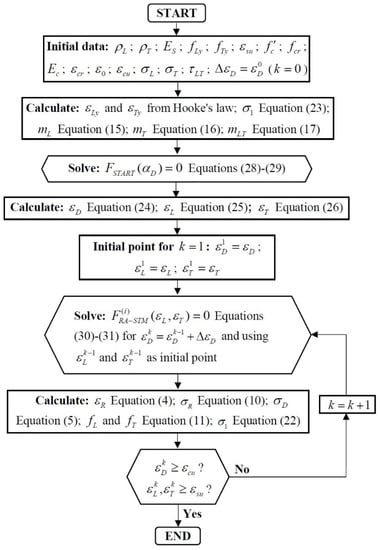
Figure 4.
Flowchart.
- Specify the initial data: , , , , , , , , , , , , , , , and . The meaning of the new parameters is: is the path’s increment for the principal compressive concrete strain (), and and are the conventional ultimate values for steel reinforcement in tension and concrete in compression, respectively. The first value for the principal compressive strain is defined as (with superscript representing the step number of the calculation procedure).
- Calculate: and from Hooke’s law ( and , respectively); the applied principal tensile stress from Equation (23); and the proportionality coefficients (, and ) from Equations (15) to (17).
- Solve (minimize) the residual function (Equations (28) and (29)) for the variable angle .
- Calculate the average strains (, , and ) from Equations (24) to (26). These values are defined to be the initial estimates (, and ) to compute the first solution point and start the efficient RA-STM procedure.
- Compute, for each step and each incremented strain , the primary variables and by solving (minimizing) the residual functions and (Equations (30) and (31)). For each step , the initial point is defined as the solution point from the previous one ().
- Calculate, for each step , the principal tensile strain from Equation (4), the principal tensile stress in concrete from Equation (10), the principal compressive stress in concrete from Equation (5), and the tensile stresses in the longitudinal () and transverse () steel reinforcements from Equation (11) and recalculate the applied principal tensile stress from Equation (22).
- If one of the failure criteria is reached (, or ), the calculation procedure ends; otherwise, repeat steps 5 and 6.
In this study, the ultimate strains ( and ) were defined from Eurocode 2 clauses [37]. The code for the efficient RA-STM procedure was implemented in MATLAB [38], and Equations (29) and (31) were numerically solved with the least-squares method.
3. Comparative Analysis with Experimental Results
In this section, the predictions from the efficient RA-STM procedure for the envelope – curves of RC panels under cyclic shear are compared with the experimental results found in the literature. For this, the experimental results from twelve RC panels tested under proportional cyclic shear with the Universal Panel Tester at the University of Houston were used—namely, series CA, CB, CD, CE, and CF [23]. As referred to in the introduction section, the number of tested RC panels under cyclic shear in the University of Houston is much higher than the ones in the other referred facilities. In addition, the used testing device incorporated a servo control system that was able to perform strain-controlled tests with proportional loading, allowing them to record the post-yield hysteretic loops with much more accuracy. This feature was considered to be important in this study in order to draw with accuracy the envelope curves from the given experimental hysteretic – loops. Furthermore, unlike the other referred studies [20,25], reference [23] reported the numerical values related to the key points and properties of the experimental hysteretic loops. It should also be mentioned that three additional RC panels were tested by Mansour in 2001 [22] (Series CVE) under different loading conditions—namely, 1-D cyclic loading—with the aim to study the effects of the loading stress state. The experimental results of these panels were not used in this study, because the panels were not tested under proportional loading.
Figure 5 illustrates the loading condition and reinforcement layout of the reference RC panels from reference [23]. Two variables were studied: the angle of steel reinforcement with respect to the applied vertical stress () and the reinforcement ratios ( and ), which can be symmetrical or not. The RC panels with #4 or #6 rebars were 1397 × 1397 × 178 mm in size, while the RC panels with #8 rebars mm were 1397 × 1397 × 203 mm in size. All the panels incorporated two layers of steel grids. The steel reinforcements consisted of grade 60 deformed bars with cross-sectional areas of 129 mm2 (#4 rebar), 284 mm2 (#4 rebar), and 510 mm2 (#8 rebar), with spacing ranging from 188 to 267 mm in both the L and T directions. The concrete compressive strength was maintained approximately constant with a target value of 42 MPa.
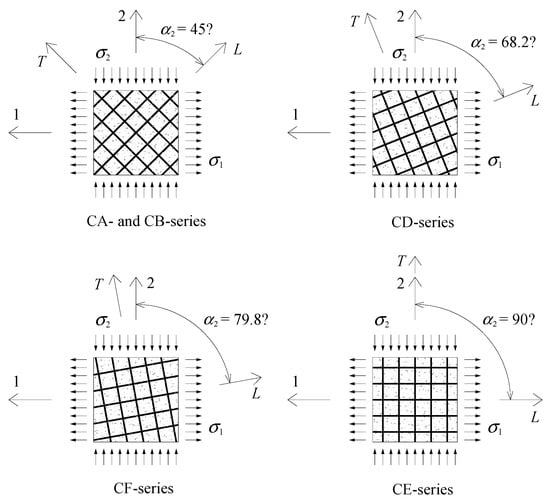
Figure 5.
Loading condition and reinforcement layout of the reference RC panels.
As illustrated in Figure 5, the panels were tested under symmetrical biaxial stresses in the 1 and 2 reference frames (). As a consequence, all the panels were tested under pure cyclic shear () in the reference frame with an angle of 45° for the 1 and 2 reference frames (see Figure 5). Under cyclic loading, the shear stresses alternated between positive and negative values with the increasing magnitude until failure of the RC panels. More details about the RC panels and the loading procedure can be found in reference [23].
Table 1 summarizes some of the main properties for each of the reference RC panels. The Young’s modulus and the yielding strength for the steel reinforcements varied from 188.9 to 223.2 GPa and from 424 MPa and 453 MPa, respectively, depending on the used rebars. Other properties for the materials not specified in reference [23] were computed in this study from Eurocode 2 [38]—namely, by a correlation with . This was done for the tensile concrete strength under a biaxial state (), and Young’s modulus for concrete ().

Table 1.
Main properties of the reference reinforced concrete (RC) panels [23].
The monotonic response of each reference RC panel from Table 1—namely, the envelope – curves—was computed with the efficient RA-STM procedure. For all tested panels, the presented experimental – loops in reference [23] refer to a reference frame with the angle of 45° with respect to the 1 and 2 reference frames (see Figure 5). As referred to before, in such reference frames, the panels were tested under pure cyclic shear. For RC panels from the CA and CB series, such a 45° reference frame (called here the L′-T′ reference frame) coincides with the L-T reference frame, which coincides with the direction of the longitudinal and transverse reinforcements (Figure 5). However, for RC panels from CD, CE and CF series, the L′-T′ reference frame does not coincide with the L-T reference frame (Figure 5). In this study, the theoretical monotonic – curves for all the RC panels were computed with respect to the L′-T′ reference frame and considering the RC panels under pure monotonic shear (such curves are named “envelope curves” from now on). Hence, for the RC panels from CD, CE and CF series, an equivalent steel grid reinforcement with equivalent ratios and was computed by using the usual transformation rules for reference frames under rotation by knowing and , and the angle the L-T reference frame must rotate to coincides with the L′-T′ reference frame. For such panels, the equivalent reinforcements ratios and were considered as inputs in the efficient RA-STM procedure.
Regarding the damage coefficient to be incorporated in the monotonic - curve for concrete in compression (Section 2.2.1, Equations (5) and (6)), in this study, the strain cannot be considered as Mansour and Hsu [24] defined it, i.e., the maximum compression strain normal to the compression direction under consideration and which occurred in the previous loading cycle. In this study, the strain was simply incremented monolithically with small steps until the conventional failure of the RC panel was reached (Section 2.3.4). Initially, a conventional definition of the strain was adopted for this study—namely, being the compression strain in concrete considered in the previous step of the numerical calculation procedure. After some calculation attempts, the following was observed:
- For RC panels whose failure was imposed by the steel reinforcement in tension, it was observed that the incorporation of the damage coefficient had no noticeable effect on the theoretical envelope curves.
- For RC panels whose failure was imposed by the concrete in compression, the incorporation of the damage coefficient led to some convergence problems after the peak shear stress.
Mansour in 2001 [22] studied the variation of the parameter in Equation (6) in order to find which value better fitted his experimental results. From this analysis, it can be observed that the incorporation and modification of the damage parameter mainly influenced the post-peak part of the hysteretic loops. In fact, until the peak shear stress is reached, no noticeable influence in the envelope - curve for concrete in compression due to the incorporation of the damage coefficient is observed when compared to the monotonic one. This explains the observation previously stated for RC panels whose failure was imposed by the steel reinforcement in tension. For such panels, the envelope curves do not show a descending branch in the ultimate stage, since the ultimate behavior is determined by the yielding of the reinforcement. Unlike RC panels whose failure is imposed by the concrete in compression, the experimental curves usually show a descending branch after the peak load. As discussed in the introduction section, the RA-STM does not predict very well the post-peak behavior of RC panels under in-plane loading. This can explain the convergence issues previously reported for such panels when the damage coefficient is incorporated.
Based on the above, and since no noticeable influence is observed until the peak load is reached in the envelope curves due to the incorporation of the damage coefficient, it was decided to not incorporate such parameter in the monotonic - curve for concrete in compression to compute the envelope curves of each reference RC panel from Table 1 with the efficient RA-STM procedure.
In Figure 6 and Figure 7, the theoretical envelope curves from the efficient RA-STM procedure are drawn against the experimental ones for each reference RC panel. It should be referred to that the experimental envelope curves were drawn from the experimental hysteretic loops reported in reference [23], as illustrated in Figure 8. Figure 6 and Figure 7 includes graphs with two envelope curves, the theoretical one computed with the efficient RA-STM procedure (“eff RA-STM”) and the experimental one (“Exp.”). Both envelope curves for positive (“(+)”) and negative (“(−)”) shear loading directions are presented. Since only envelope curves are studied here, neither the experimental hysteretic loops nor the theoretical hysteretic loops computed with the CSMM and reported in references [22,23] are presented in Figure 6 and Figure 7.
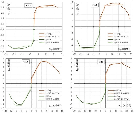
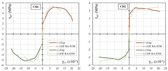
Figure 6.
Envelope curves for the reference RC panels (CA2, CA3, CA4, CB3, CB4 and CD2).
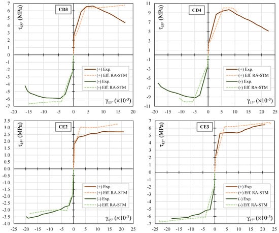
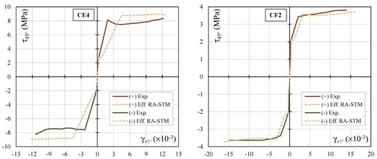
Figure 7.
Envelope curves for the reference RC panels (CD3, CD4, CE2, CE3, CE4 and CF2).
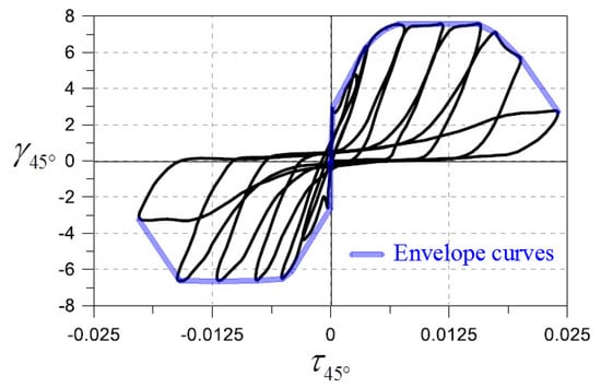
Figure 8.
Drawing the experimental envelope curve from the hysteretic loops.
Figure 6 and Figure 7 shows that, in general, the theoretical envelope curves computed with the efficient RA-STM procedure are in reasonably good agreement with the experimental ones, for both positive and negative shear loading. The results show that, for most of the reference RC panels, the efficient RA-STM procedure captures well the global response of the reference RC panels until the maximum shear stress, including the transition from the uncracked to the cracked stage and, also, the yielding point. Regarding the descending branch observed for some RC panels after the peak shear stress, the less good results from the efficient RA-STM procedure were previously justified. However, for a precheck analysis or a predesign, this feature of the envelope curves is not very important.
For a quantitative comparative analysis, Table 2, Table 3, Table 4 and Table 5 present, for each reference RC panel, the experimental and theoretical coordinates for some important key points of the envelope curves—namely, the points corresponding to concrete cracking, reinforcement yielding, and maximum shear stress. Table 2 and Table 3 present the referred values associated with the positive (“+”) loading shear direction, while Table 4 and Table 5 present the same values for the negative (“−”) loading shear direction. In the referred tables, the following experimental (“exp”) and theoretical (“th”) values are presented: the cracking shear stresses ( and ) and corresponding shear strains ( and ), the yielding shear stresses ( and ) and corresponding shear strains ( and ), and the peak shear stresses ( and ) and corresponding shear strains ( and ). For RC panels with asymmetrical reinforcement ratios, and for each shear loading direction, the yielding point corresponds to the one where the first reinforcement (longitudinal or transverse) yielded. In addition to the previous parameters, the experimental and theoretical values for the envelope shear ductility factor ( and ), as defined in reference [23], are also presented. Such a parameter, which constitutes a measure of the ductility of the RC panels under shear, is calculated as follows:
where is the ultimate shear strain, which is defined as follows [23]: (1) When the envelope curve exhibits no descending branch, is simply the shear strain corresponding to the last point of the curve; (2) when the envelope curve exhibits a descending branch, is defined as the shear strain of the point in the curve corresponding to in the descending branch.

Table 2.
Comparative analysis: positive (+) loading shear direction (cracking and yielding points).

Table 3.
Comparative analysis: positive (+) loading shear direction (peak point and ductility).

Table 4.
Comparative analysis: negative (−) loading shear direction (cracking and yielding points).

Table 5.
Comparative analysis: negative (−) loading shear direction (peak point and ductility).
The experimental values of the parameters referred previously and incorporated into Table 2 and Table 3 were reported in reference [23]. Finally, Table 2 also presents the ratios of the experimental to the theoretical incorporated values and, also, for each of them, the mean (), the standard deviation (), and the coefficient of variation ().
The results in Table 2, Table 3, Table 4 and Table 5 show that the efficient RA-STM procedure predicts reasonably well both the cracking shear stress and the yielding shear stress (with ) and with a very acceptable degree of dispersion (). For the peak shear stress, , the predictions are better ( and ).
For the shear strains corresponding to the cracking shear stress (), the results show that the model noticeably tends to underestimate this parameter () and with a high degree of dispersion (). This is probably because this parameter is very small to be recorded experimentally or to be obtained from the experimental hysteretic loops with sufficient accuracy. This problem was also reported in previous studies [33,34]. Regarding the shear strains corresponding to the yielding shear stress () and the peak shear stress (), the results show that these parameters tend to be somewhat underestimated () and with a high degree of dispersion (). As observed in previous studies, smeared truss models, such as the RA-STM, show a higher difficulty in predicting the deformation of RC panels at the ultimate stages very well. A smeared truss model constitutes a discontinuous model that does not consider with a very high accuracy the influence of the real stiffness of the member, even if it incorporates a smeared constitutive law for tensile concrete. In addition, the used model in this study did not incorporate cyclic constitutive laws that usually account for the stiffness loss of the materials during the loading cycles, which influences the global stiffness of the RC panel in the ultimate stage. This can explain why the predicted deformations at the ultimate stage tend to be underestimated by the model. However, the previously referred parameters related to the shear strains can be considered not very important for the design, at least for the first check analysis.
Regarding the shear ductility factor (), the results show that the model somewhat tends to overestimate the shear ductility of the reference panels () and with a high degree of dispersion (). This is mainly due to the reasons stated in the previous paragraph and also because, as previously explained in this article, the efficient RA-STM procedure shows difficulties to predict well the post-peak behavior of the envelope curves—namely, the descending branch. The shear ductility factor depends on the shear strains at the ultimate stage.
4. Conclusions
In this study, the monotonic version of the efficient RA-STM procedure was used to predict the envelope curves of RC panels under cyclic shear. From the results obtained through this study, the following main conclusions can be drawn:
- In spite of being a monotonic model, previously proposed and checked for RC panels under monotonic shear, the efficient RA-STM procedure is able to predict with reasonably good agreement the shape of the experimental envelope curves of the studied RC panels under cyclic shear. This is true, at least, until the peak shear stress is reached. The obtained theoretical curves capture well the global experimental envelope response of the RC panels under cyclic shear, including the transition from the uncracked to the cracked stage.
- In particular, the monotonic efficient RA-STM procedure predicts reasonably well some key shear stresses that are important for the design—namely, the cracking shear stress, the yielding shear stress, and the peak shear stress of the RC panels under cyclic shear.
- For the shear strains corresponding to the studied key shear stresses, the monotonic efficient RA-STM procedure showed a higher difficulty in predicting well the experimental values (they tend to be underestimated by the model). However, this drawback can be considered less important, because such parameters are not very important for the design, at least for a first check analysis.
- As a consequence of the stated in the previous point, the monotonic model also showed a higher difficulty in predicting well the ductility of the RC panels under cyclic shear (it tends to be overestimated by the model). This drawback can be considered somewhat relevant, since ductility is a key parameter for the design—namely, for the structures located in seismic areas.
The above-mentioned shows that the efficient RA-STM procedure, in spite of being a model for RC panels under monotonic shear, can be considered a reliable model to predict reasonably well the envelope curves for RC panels under cyclic shear, at least until the peak shear stress is reached. In addition, it also predicts reasonably well important key shear stresses—namely, the ones corresponding to the cracking, yielding, and maximum shear capacities. These good results do not include the prediction of the shear ductility, which tends to be overestimated. In spite of this last drawback, it can be concluded that the monotonic efficient RA-STM procedure can be used at least for a precheck analysis or a predesign of RC panels under cyclic shear before more complex and reliable models are used.
Author Contributions
Conceptualization, L.B.; methodology, L.B.; validation, L.B.; formal analysis, S.S.; investigation, S.S.; data curation, S.S.; writing—original draft preparation, L.B.; writing—review and editing, L.B. and S.S.; and supervision, L.B. All authors have read and agreed to the published version of the manuscript.
Funding
This research received no external funding.
Institutional Review Board Statement
Not applicable.
Informed Consent Statement
Not applicable.
Data Availability Statement
Data is contained within the article.
Conflicts of Interest
The authors declare no conflict of interest.
References
- Hsu, T.T.C.; Mo, Y.L. Unified Theory of Concrete Structures; John Wiley & Sons Ltd.: Chichester, UK, 2010; p. 500. [Google Scholar]
- Vecchio, F.; Collins, M.P. Stress-strain Characteristic of Reinforced Concrete in Pure Shear. IABSE Colloquium, Advanced Mechanics of Reinforced Concrete, Delft, Final Report; International Association of Bridge and Structural Engineering: Zurich, Switzerland, 1981; pp. 221–225. [Google Scholar]
- Vecchio, F.J.; Collins, M.P. Response of Reinforced Concrete to in Plane Shear and Normal Stresses; Report No.82-03; University of Toronto: Toronto, ON, Canada, 1982. [Google Scholar]
- Vecchio, F.J.; Collins, M.P. The modified Compression-Field Theory for Reinforced Concrete Elements Subjected to Shear. ACI J. 1986, 83, 219–231. [Google Scholar]
- Balakrishnan, S.; Murray, D.W. Prediction of R/C Panels and Deep Beam Behavior by NLFEA. J. Struct. Eng. 1988, 114, 2323–2342. [Google Scholar] [CrossRef]
- Crisfield, M.A.; Wills, J. Analysis of R/C Panels Using Different Concrete Models. J. Eng. Mech. 1989, 115, 578–597. [Google Scholar] [CrossRef]
- Kaufmann, W.; Marti, P. Structural Concrete: Cracked Membrane Model. J. Struct. Eng. 1998, 124, 1467–1475. [Google Scholar] [CrossRef]
- Vecchio, F.J. Disturbed Stress Field Model for Reinforced Concrete: Formulation. J. Struct. Eng. 2000, 126, 1070–1077. [Google Scholar] [CrossRef]
- Vecchio, F.J. Disturbed Stress Field Model for Reinforced Concrete: Implementation. J. Struct. Eng. 2001, 127, 12–20. [Google Scholar] [CrossRef]
- Belarbi, A.; Hsu, T.T.C. Constitutive Laws of Concrete in Tension and Reinforcing Bars Stiffened by Concrete. Struct. J. Am. Concr. Inst. 1994, 91, 465–474. [Google Scholar]
- Belarbi, A.; Hsu, T.T.C. Constitutive Laws of Softened Concrete in Biaxial Tension-Compression. Struct. J. Am. Concr. Inst. 1995, 92, 562–573. [Google Scholar]
- Pang, X.B.; Hsu, T.T.C. Behavior of Reinforced Concrete Membrane Elements in Shear. Struct. J. Am. Concr. Inst. 1995, 92, 665–679. [Google Scholar]
- Zhang, L.X.; Hsu, T.T.C. Behavior and Analysis of 100 MPa Concrete Membrane Elements. J. Struct. Eng. 1998, 124, 24–34. [Google Scholar] [CrossRef]
- Pang, X.B.; Hsu, T.T.C. Fixed-Angle softened truss model of reinforced concrete. Struct. J. Am. Concr. Inst. 1996, 93, 197–207. [Google Scholar]
- Hsu, T.T.C.; Zhang, L.X. Nonlinear Analysis of Membrane Elements by Fixed-Angle Softened-Truss Model. Struct. J. Am. Concr. Inst. 1997, 94, 483–492. [Google Scholar]
- Hsu, T.T.C.; Zhu, R.R.H. Softened Membrane Model for Reinforced Concrete Elements in Shear. Struct. J. Am. Concr. Inst. 2002, 99, 460–469. [Google Scholar]
- Zhu, R.H.; Hsu, T.T.C. Poisson Effect of Reinforced Concrete Membrane Elements. Struct. J. Am. Concr. Inst. 2002, 99, 631–640. [Google Scholar]
- Zhu, R.H.; Hsu, T.T.C.; Lee, J.Y. Rational Shear Modulus for Smeared Crack Analysis of Reinforced Concrete. Struct. J. Am. Concr. Inst. 2001, 98, 443–450. [Google Scholar]
- Belletti, B.; Cerioni, R.; Iori, I. Physical Approach for Reinforced-Concrete (PARC) Membrane Elements. J. Struct. Eng. 2001, 127, 1412–1426. [Google Scholar] [CrossRef]
- Stevens, N.J.; Uzumeri, S.M.; Collins, M.P. Reinforced Concrete Subjected to Reversed Cyclic Shear—Experiments and Constitutive Model. Aci Struct. J. 1991, 88, 135–145. [Google Scholar]
- Mansour, M.; Lee, J.Y.; Hsu, T.T.C. Cyclic stress-strain curves of concrete and steel bars in membrane elements. J. Struct. Eng. 2001, 127, 1402–1411. [Google Scholar] [CrossRef]
- Mansour, M. Behavior of Reinforced Concrete Membrane Elements under Cyclic Shear: Experiments to Theory. Ph.D. Thesis, University of Houston, Houston, TX, USA, 2001. [Google Scholar]
- Mansour, M.; Hsu, T.T.C. Behavior of reinforced concrete elements under cyclic shear. I: Experiments. J. Struct. Eng. 2005, 131, 44–53. [Google Scholar] [CrossRef]
- Mansour, M.; Hsu, T.T.C. Behavior of reinforced concrete elements under cyclic shear. II: Theoretical model. J. Struct. Eng. 2005, 131, 54–65. [Google Scholar] [CrossRef]
- Ohmori, N.; Takahashi, T.; Tsuboto, H.; Inoue, N.; Kurihara, K.; Watanabe, S. Experimental studies on nonlinear behavior of reinforced concrete panels subjected to cyclic in-plane shear. J. Struct. Constr. Eng. AIJ 1989, 403, 105–118. (In Japanese) [Google Scholar]
- Hsu, T.T.C.; Belarbi, A.; Pang, X.B. A universal panel tester. J. Test. Eval. 1995, 23, 41–49. [Google Scholar]
- Orakcal, K.; Massone, L.M.; Ulugtekin, D. A Hysteretic Constitutive Model for Reinforced Concrete Panel Elements. Int. J. Concr. Struct. Mater. 2019, 13, 51. [Google Scholar] [CrossRef]
- Greene, G.G.; Belarbi, A. Model for Reinforced Concrete Members under Torsion, Bending, and Shear. I: Theory. J. Eng. Mech. 2009, 135, 961–969. [Google Scholar] [CrossRef]
- Silva, J.; Horowitz, B.; Bernardo, L. Efficient Analysis of Beam Sections Using Softened Truss Model. Aci Struct. J. 2017, 114, 765–774. [Google Scholar] [CrossRef][Green Version]
- Wong, H.F.; Kuang, J.S. Predicting shear strength of RC interior beam-column joints by modified rotating-angle softened-truss model. Comput. Struct. 2014, 133, 12–17. [Google Scholar] [CrossRef]
- Bernardo, L.F.A.; Andrade, J.M.A.; Nunes, N.C.G. Generalized softened variable angle truss-model for reinforcement concrete beams under torsion. Mater. Struct. 2015, 48, 2169–2193. [Google Scholar] [CrossRef]
- Ji, T. A new algorithm for the rotating-angle, softened-truss model of reinforced concrete elements. Mag. Concr. Res. 2005, 57, 353–360. [Google Scholar] [CrossRef]
- Bernardo, L.F.A.; Filho, B.M.V.C.; Horowitz, B. Predicting the behavior of prestressed concrete membrane elements by refined rotating-angle softened-truss model with efficient solution procedure. Struct. Concr. 2020, 21, 934–948. [Google Scholar] [CrossRef]
- Bernardo, L.F.A.; Filho, B.M.V.C.; Horowitz, B. Refinement of the rotating-angle softened truss model with efficient solution for RC membranes. Eng. Struct. 2020, 213, 110552. [Google Scholar] [CrossRef]
- Bernardo, L.F.A.; Filho, B.M.V.C.; Horowitz, B. Predicting the Behavior of FRP-Strengthened RC Membrane Elements with Efficient Rotating-Angle Softened-Truss Model Procedure. Mater. Struct. 2021, in press. [Google Scholar] [CrossRef]
- Jeng, C.H.; Hsu, T.T.C. A softened membrane model for torsion in reinforced concrete members. Eng. Struct. 2009, 31, 1944–1954. [Google Scholar] [CrossRef]
- NP EN 1992–1-1. Eurocode 2: Design of Concrete Structures—Part 1: General Rules and Rules for Buildings; European Committee for Standardization—CEN: Brussels, Belgium, 2010. [Google Scholar]
- MathWorks. MATLAB_R2018a. 2018
Publisher’s Note: MDPI stays neutral with regard to jurisdictional claims in published maps and institutional affiliations. |
© 2021 by the authors. Licensee MDPI, Basel, Switzerland. This article is an open access article distributed under the terms and conditions of the Creative Commons Attribution (CC BY) license (http://creativecommons.org/licenses/by/4.0/).