1. Introduction
As the core equipment of underwater detection systems, the stable operation and safety of towed line arrays directly impact a vessel’s underwater early warning, surveillance, and reconnaissance capabilities. During combat training and operations, towed line arrays must maintain stable formation and safe diving depths in complex marine environments. However, when subjected to the combined effects of currents, waves, towing speed, cable length, and other factors, towed array systems are prone to depth instability, array instability, or even structural damage. Excessively low speed or short cable length causes the array to approach the surface too closely, leading to severe interference from surface turbulence and navigation noise, resulting in a sharp decline in detection performance. Conversely, excessively high speed or cable length can cause winches and cables to exceed tension limits, posing major safety hazards such as cable breakage and equipment damage. Therefore, systematically studying the “safe operating limits” of towed array systems under multi-parameter constraints and defining their safe operating parameter ranges under different conditions holds significant engineering value for ensuring long-term stable operation, enhancing detection accuracy, and improving mission success rates.
Tao optimized the streamlined designs of tow cables and tow bodies for high-speed, deep-draft towing systems using Fluent simulations [
1]. Focusing on cable and body drag, the drag coefficient was significantly reduced, enabling stable towing at 100 m depth during 15 knots of ship speed. This validated the system’s feasibility at high speeds. Findings indicate that at low ship speeds, increasing cable length markedly accelerates the towing body’s descent rate. At high speeds, however, the sinking effect flattens as cable length increases. Li et al. analyzed the influence of wing plate angle of attack, speed, and cable length on towed body depth control, spread width, and dry-end tension through lake trials [
2]. They fitted a multivariate nonlinear regression function and proposed depth control and spreading strategies suitable for short-cable systems. Zhang studied the dynamic response of a towed body under disturbances using a 3000 m ultra-deepwater towing system [
3]. Employing a coupled simulation method combining the concentrated mass approach with STAR-CCM+ catenary theory and DFBI modules, they optimized attitude stability by adding stabilizing wings. This provides crucial reference for stability design in deepwater towing systems. However, this research has yet to clearly define the system’s safe operating limits under complex sea conditions. Sun et al. proposed the Node Position Finite Element Method to directly compute cable positions, eliminating the need for decoupling rigid body motion from overall motion in traditional finite element methods [
4]. Yang et al. employed the ALE-ANCF (Absolute Node Coordinate Framework with Arbitrary Lagrangian-Eulerian description) to model variable-length flexible towing cables [
5]. They analyzed the dynamic relationship between cable length and towing depth under scenarios of minor and major cable length adjustments, investigating the influence of varying towing speeds and sea conditions on cable tension and towed body attitude. Xu employs a concentrated mass approach to establish a discrete model of the cable in a reverse towing system, deriving its kinematic and dynamic equations. The study focuses on the dynamic prediction of cable length during deployment [
6].
From the macro-perspective of regulatory compliance and operational safety, classification society standards, the “Marine Towage Guide” of China Classification Society, which incorporates the IMO guidelines, enforce strict quantitative constraints on towing systems, including the Minimum Breaking Load of towlines and minimum safe speeds [
7]. Furthermore, Flag State administrations legally enforce these operational limits by mandating statutory verifications and the issuance of a ‘Certificate of Fitness for Towage’. To meet these regulatory limits in engineering practice, Liu proposed empirical calculation methods for towline tension during ocean towing, integrating the resistance from wind, waves, and currents to ensure structural safety [
8]. Ni systematically analyzed the selection of towing vessels and the configuration criteria for towing rigging, providing practical evaluation methods to prevent secondary maritime risks induced by structural failure [
9].
In summary, significant scientific breakthroughs have been achieved in hydrodynamic drag optimization, advanced numerical modeling of flexible cables, and specific operational control strategies. Existing studies primarily focus on single-parameter hydrodynamic responses at specific speeds or emphasize the purely mechanical convergence of numerical solvers. There is a lack of a holistic, multi-parameter coupled safety evaluation framework. Specifically, systematic research is still needed on how to integrate hard physical limits with complex towing parameters during high-speed dynamic shifts.
This paper aims to investigate the design of safe operating limits for towed line arrays under multiple parameter constraints. Common towed cable modeling methods include the finite difference method [
10], the lumped mass method [
11,
12,
13], the direct integration method [
14], and the finite element method [
15]. Among these, the lumped mass method possesses clear physical significance and a straightforward algorithm, making it widely applied in research on towing system manipulation. Based on the concentrated mass method, this study employs OrcaFlex to establish a parametric numerical model of the towing system [
16]. Utilizing the Python 3.9.12 interface, batch calculations and data analysis are performed across the entire parameter space of speeds ranging from 2 to 18 knots and cable lengths from 100 to 2400 m. The key issue addressed in this study is how to precisely quantify the coupled influence of speed and cable length on the diving depth of the line array and the tension at the winch end. Based on this, an intuitive “Safe Maneuvering Envelope” is synthesized by integrating tension and depth constraints. The research outcomes will provide a comprehensive theoretical foundation and quantitative guidance for the safe operation of this towed array type, holding significant practical value for enhancing the operational safety and reliability of underwater towed systems.
To achieve the aforementioned objectives and provide quantitative operational guidance, the remainder of this paper is organized as follows.
Section 2 details the dynamic modeling process of the towed array based on the Lumped Mass Method and establishes a multi-constraint optimization model integrating cable structural variables with operational parameters.
Section 3 presents the parametric numerical simulation results, analyzing the impact of main cable outer diameter on system safety, investigating the dynamic response under the dual-parameter coupling of vessel speed and deployed cable length, and ultimately constructing the Safe Maneuvering Envelopes (SME) for different main cable specifications.
Section 4 provides an in-depth discussion on the “interval drift” characteristics and “tension truncation” effects of the safety boundaries revealed by the simulations, evaluates the engineering applicability of different designs, and explores the practical value of this visualized decision-making tool. Finally,
Section 5 summarizes the main findings of the study, elucidates the evolutionary laws of the safety boundaries under multi-parameter coupling, and offers prospects for future research on dynamic envelopes in complex marine environments.
2. Materials and Methods
2.1. Modeling of Towed Array Using the Lumped Mass Method
The towed array’s dynamic model is established by discretizing it using the Lumped Mass Method. This approach divides the towed cable of length L into N nodes and N-1 elements from the trailing end to the leading end. Node numbers range from 1 at the winch end to N at the array’s trailing end. Each node
possesses a concentrated mass
, encompassing both the structural mass of that array segment and added mass. Adjacent nodes
and
+ 1 are connected by a massless spring-damper unit, simulating the cable’s axial stiffness
and internal damping
[
17,
18,
19].
For any node , analyze all forces acting at that point, including axial elastic force , gravitational and buoyant forces , and hydrodynamic forces .
(1) Axial elastic force :
Generated by the expansion/contraction between two adjacent segments (element
and element
).
where:
is the tension vector on element
(connecting nodes
and
+ 1),
.
Based on Hooke’s law and damping, the magnitude of
is:
In the equation: is the original length of the th element in an unloaded state; is the rate of change of length for the th element; represents the axial strain rate of this element; is the axial damping coefficient of the th element, which is governed by the material properties of the cable.
The direction of the tension
is along the unit vector pointing from node
to node
.
where:
is the instantaneous velocity of the
th element.
(2) Gravity and buoyancy
:
where:
is the concentrated mass at node
;
is the density of seawater;
is the volume of displaced water at node
;
is the gravitational acceleration vector.
(3) Hydrodynamics :
When the cable moves through water, it experiences fluid drag and lift. Based on the Morison equation, to accurately simulate the hydrodynamic characteristics of the slender flexible cable, the fluid dynamic force is decomposed into a normal component
perpendicular to the cable deflection and a tangential component
parallel to the cable direction:
where the normal and tangential drag forces are calculated respectively as:
where:
and
are the normal and tangential fluid drag coefficients, respectively;
and
are the outer diameter and instantaneous length of the
th element;
and
are the normal and tangential components of the relative fluid velocity vector
;
According to Newton’s second law, for each node
:
where:
is the acceleration vector of node
.
Substituting the force analysis yields a system of second-order ordinary differential equations:
where
.
The first segment node
= 1 is connected to the tugboat. In the global coordinate system, this point’s position is fixed at the vessel’s towing point, and its velocity matches the vessel’s speed [
20,
21].
where:
represents the spatial coordinates of the towing point, which is a constant value in static analysis. In this simulation, the coordinates
are set to (0, 0, 0);
denotes the ship’s speed, i.e., the towing velocity.
Node
= N represents the trailing end of the line array. Since the flexible line array does not carry a heavy towed body at its tail. This model simplifies it as a free end, meaning this point is unaffected by elastic tension from adjacent elements. Its boundary condition is derived from mechanical equilibrium:
where
is the tension vector of the terminal element (connecting nodes N − 1 and N). Based on Equations (2) and (11), we have
In static analysis,
, thus the condition simplifies to the instantaneous length of the terminal element equaling its original length
. This indicates the element is in its natural state, neither under tension nor compression [
22,
23].
This study primarily conducts static analysis to determine the equilibrium configuration of the system at constant cruise speed. At static equilibrium, the acceleration and velocity of all nodes are zero (
). Consequently, the control equations simplify to a nonlinear system of algebraic equations concerning node positions
:
where
.
This system of equations, together with the aforementioned boundary conditions, constitutes a complete boundary value problem. The solution is obtained using the Newton-Raphson iteration method. This algorithm iteratively solves the system’s Jacobian matrix, enabling rapid and stable convergence to the system’s static equilibrium solution.
2.2. Optimization Model for Towed Line Array Design Parameters
Based on simulation analysis data, a system optimization model integrating cable structural parameters and operational parameters was constructed. The model uses the main cable outer diameter as the design dimension and incorporates the functional relationship between unit length, mass, and outer diameter, thereby achieving integrated joint optimization from “cable selection” to “operational settings”. Its core objective is to translate the safety performance boundaries obtained from simulation into explicit constraints. Under these stringent physical safety limits, the model identifies optimal cable specifications and corresponding safe operating parameter combinations for different mission scenarios, presenting the optimization results in an intuitive “safe operating window” format [
24,
25,
26].
The model development follows a “structure-operation coupling optimization” technical approach. First, through serial simulations of three main cable outer diameters , dynamic response datasets were obtained for combinations of ship speed and deployed cable length . Key outputs include steady-state diving depth and winch-end breaking tension . The model establishes a physical link between cable structural properties and dynamic responses via known functions . Subsequently, the system’s physical safety limits—namely the permissible depth constraint for the cable array and the allowable tension considering safety factors —were mapped as constraint boundaries onto this dataset. Finally, the optimization problem is defined as follows: within the hybrid design space spanned by discrete variables and continuous variables , identify the feasible region satisfying all safety constraints and maximize the operational range within this region—the Safe Maneuvering Envelope—to establish an optimal decision space for setting parameters during towing operations.
Mathematically, this objective is formulated to maximize the Feasible Operational Area of the system for a given main cable outer diameter
. The objective function
is defined as the integral of the Safe Maneuvering Envelope over the two-dimensional velocity-cable length
plane:
where:
denotes the valid feasible domain satisfying all physical safety limitations. The construction of this mathematical domain is strictly governed by the following variables and constraints:
The design variables in the optimization model comprise two categories: discrete structural variables and continuous operational variables:
(1) Discrete structural variable: Main cable outer diameter , constrained by the manufacturing specifications of the towed cable, its values are selected from a predefined Cable Library: .
(2) Continuous operational variables:
Sailing speed (knots): . Its range is jointly defined by tugboat capacity and mission requirements. In this simulation, the sailing speed range is 2–18 knots.
Cable length
(m):
. Its upper and lower limits are constrained by the winch’s cable capacity and the required working depth [
27,
28].
The optimization model’s constraints originate from the system’s physical limitations and operational requirements, all established based on simulation data.
(1) Diving depth safety constraint: To prevent reduced shallow detection performance due to excessive submersion of the towed line array or damage to internal components caused by excessive pressure at deep diving depths.
(2) Breaking Tension Safety Constraint:
(3) Variable Range Constraint:
Given that the discrete variable has only three possible values, a two-stage method combining discrete enumeration and continuous optimization is employed for efficient and robust solution:
(1) Outer-layer enumeration: Iterate through each main cable outer diameter value within the set .
(2) Inner-layer optimization: For each fixed , invoke the original continuous optimization model. Use the variables (sailing speed) and (cable deployment length) to solve for the corresponding safe operating window.
(3) Comprehensive Comparison: Compare the optimal objective function values achievable under the three outer diameter schemes—such as maximum safe operating speed and maximum operational window area—and combine with other factors like engineering costs and towing noise to recommend the overall optimal
combination [
29].
2.3. Validation of the Numerical Model
The subsequent construction of the Safe Maneuvering Envelope (SME) in this paper heavily relies on the prediction accuracy of the numerical model regarding the array’s depth and tension under various vessel speeds and deployed cable lengths. To comprehensively verify the accuracy of the proposed numerical model in complex fluid–structure interaction calculations, a classic three-dimensional towing benchmark in the field of ocean engineering is introduced for comparative testing.
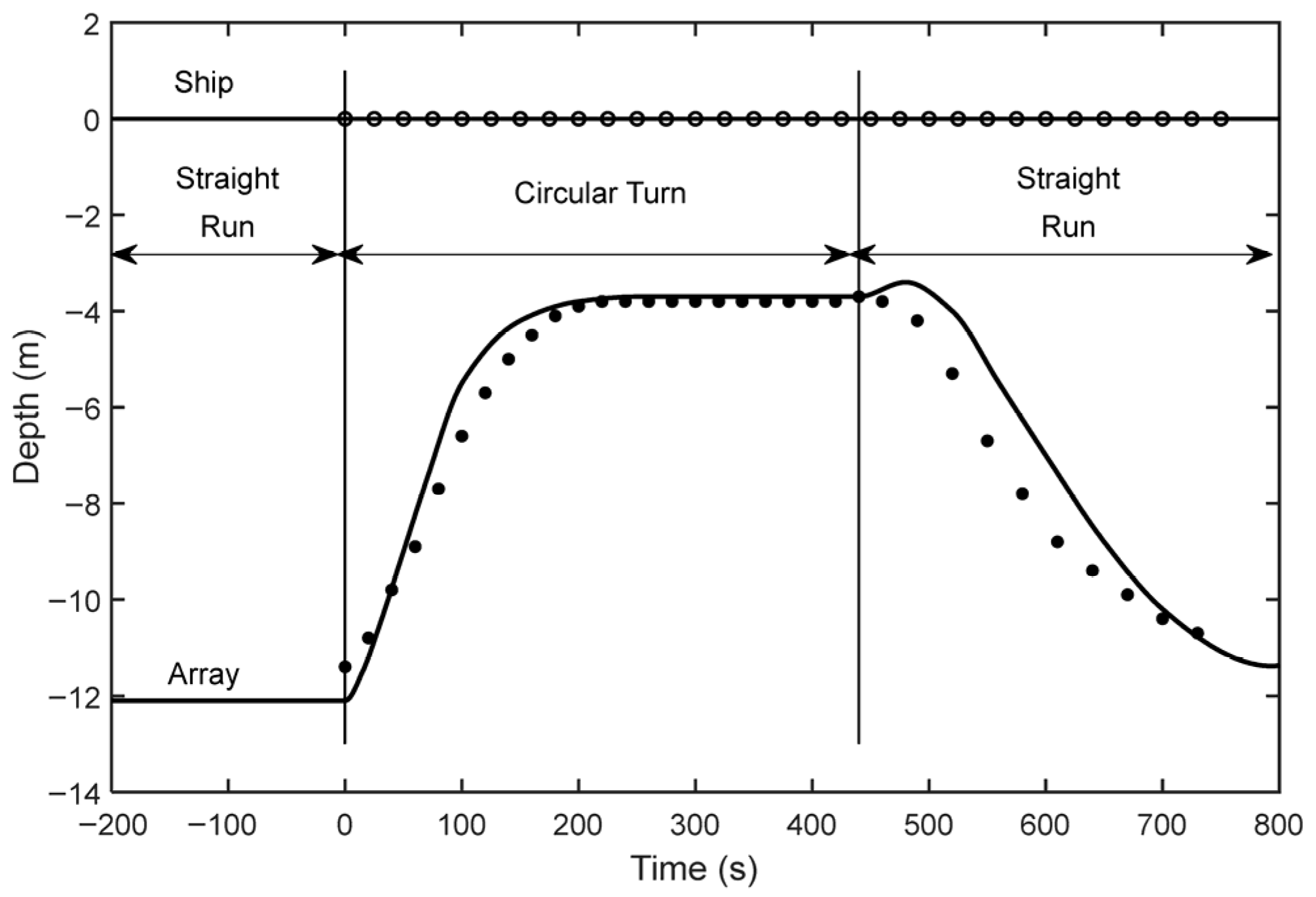
This benchmark encompasses a complete straight-line and turning maneuvering process. The system consists of a 723 m negatively buoyant tow cable, a 273.9 m neutrally buoyant horizontal line array, and a 30.5 m drogue. The simulated operating conditions are as follows: the tugboat initially performs a straight-line tow at a constant speed of 9.52 m/s, then enters a circular trajectory with a radius of 640 m for a continuous 375° turn (lasting 440 s), and finally resumes straight-line navigation. The time-history depth data of a node located 8.2 m downstream from the head of the horizontal array was extracted and compared with the classical literature results, as shown in
Figure 1.
As illustrated in
Figure 1, the simulation results of the numerical model established in this study exhibit a highly compelling agreement with the benchmark data from the classical literature. Particularly during the straight-run phases before and after the turn, the model accurately solves for the steady-state equilibrium depth of approximately −12.1 m. Furthermore, during the abrupt velocity changes induced by the turn, the model precisely reproduces the complex spatial trajectory of the array rising to the −3.8 m plateau.
This high-precision comparative result demonstrates that the adopted Lumped Mass Method model can perfectly capture the 3D spatial configuration and force characteristics of large-span towed arrays under strong fluid–structure coupling. Consequently, applying this thoroughly validated underlying model to perform multi-parameter sweep solutions under steady-state conditions (i.e., eliminating transient acceleration terms) ensures extremely high physical reliability for the output terminal tension and diving depth data. This provides a solid and credible foundation for delineating the SME boundaries in this study.
3. Results
3.1. Subsection Main Cable Specifications for Towed Array
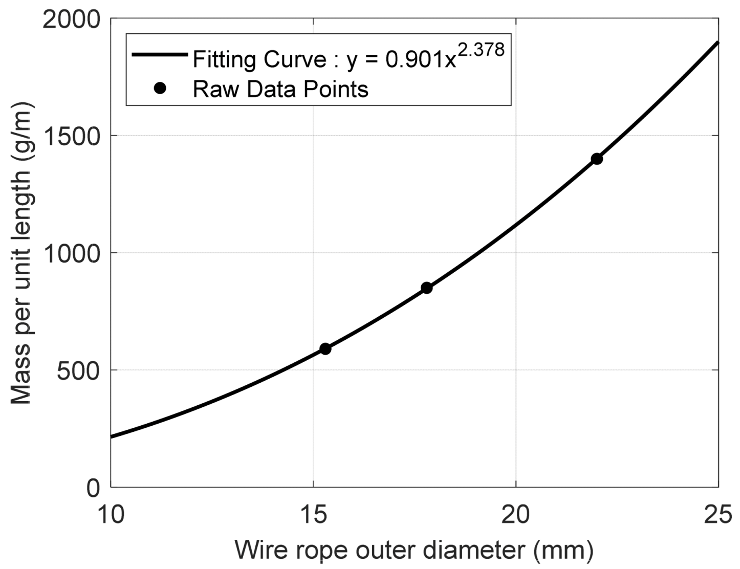
This study employs a fitting analysis of the functional relationship between experimentally measured wire rope outer diameter and its unit length mass data. From the perspectives of material mechanics and geometric structure, the unit length mass of wire rope primarily depends on its cross-sectional area and material density. For ropes with circular cross-sections, under conditions of uniform material and consistent structure, the unit length mass should be proportional to the square of the outer diameter. The cable type library table
Table 1 and fitting curve diagram
Figure 2 are shown below:
This study conducted a fitting analysis of the functional relationship between the measured outer diameter and mass per unit length of steel wire cables. Based on material mechanics and geometric structure, the mass per unit length of steel wire cables primarily depends on their cross-sectional area and material density. For cables with circular cross-sections, under conditions of uniform material and consistent structure, the mass per unit length should be proportional to the square of the outer diameter.
Through least squares regression analysis, the fitted relationship is expressed as:
The coefficient of determination exceeds 0.999, indicating the model accurately reflects the variation pattern between the two variables. The empirically determined power index of 2.378 significantly exceeds the theoretical value of 2. This deviation primarily stems from the fact that steel wire ropes are not perfectly compact solid cylinders. Their internal structure typically consists of multiple strands, and as rope diameter increases, both the number of strand layers and the proportion of gaps between wires may undergo nonlinear changes. Furthermore, to enhance the load-bearing capacity and torsional resistance of larger-diameter cables in engineering applications, the strength grade of wires is often increased or the stranding method adjusted. This causes the linear density to increase at a rate exceeding the square of the diameter, deviating from a purely geometric relationship. Thus, the fitted index b = 2.378 fundamentally reflects the influence of the actual structural complexity of steel wire ropes and their mechanical design factors on linear density [
31].
3.2. Influence of Cable Outer Diameter on Line Array Safety
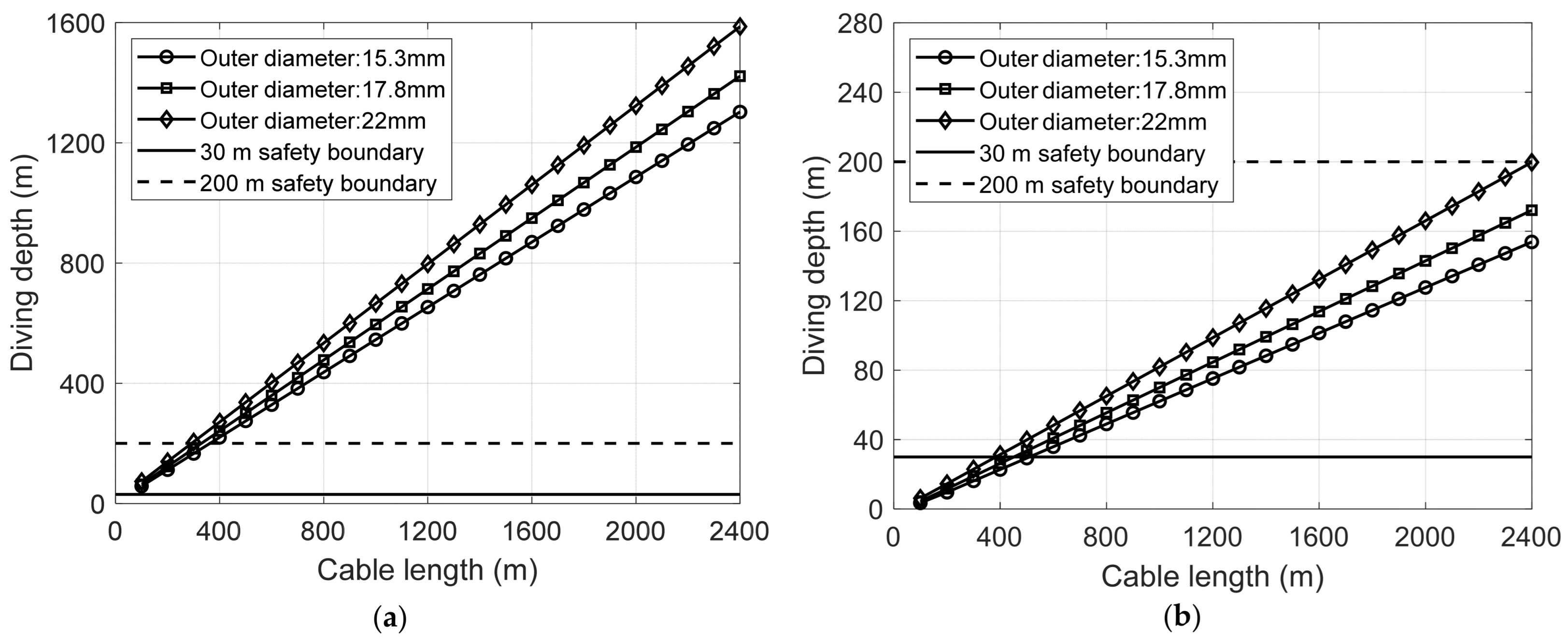
Figure 3 illustrates the variation in diving depth with cable length for three main cable specifications at 2 knots and 18 knots.
Analysis indicates that cable diameter significantly influences diving depth, exhibiting a positive correlation between the two. Under identical sailing speeds and cable deployment lengths, the 22 mm outer diameter cable achieves the greatest diving depth, while the 15.3 mm outer diameter cable reaches the shallowest depth. This disparity stems from differences in specific mass per unit length; larger-diameter cables possess greater negative buoyancy in seawater, resulting in a more pronounced sinking tendency.
Sailing speed is a key determinant of diving depth. At low speeds of 2 knots, gravitational forces primarily govern the system. With minimal fluid resistance, the cable exhibits a typical catenary curve, showing a substantial linear increase in diving depth with cable length. When fully deployed at 2400 m, all three main cable outer diameter specifications achieved submergence depths exceeding 1200 m, far surpassing the 200-m lower limit. This demonstrates that during low-speed cruising, the line array possesses substantial submergence capability, eliminating concerns about failing to achieve the 200-m maximum depth.
At high-speed operating conditions of 18 knots, hydrodynamic forces become dominant. Tangential and normal resistances on the cables increase sharply, causing severe “lifting effects” and significantly degrading diving capability. At this point, the 22 mm outer diameter main cable, leveraging its greater mass per unit length, effectively counteracts hydrodynamic lift, demonstrating optimal array position retention capability. When the cable is fully deployed to its full length of 2400 m, it just reaches the 200-m maximum diving depth threshold. In contrast, the 15.3 mm outer diameter main cable, due to its lighter self-weight, achieves only a diving depth of 155 m at the same cable deployment length. Additionally, during the initial phase with cable lengths under 400 m, substantial lift at high speeds made it difficult for some configurations to maintain depths below the minimum safe depth of 30 m. Thus, submergence depth at high speeds primarily defines the geometric lower and upper limits of the safe operating window, with larger-diameter main cables better suited for maintaining effective working depths under high-speed conditions.
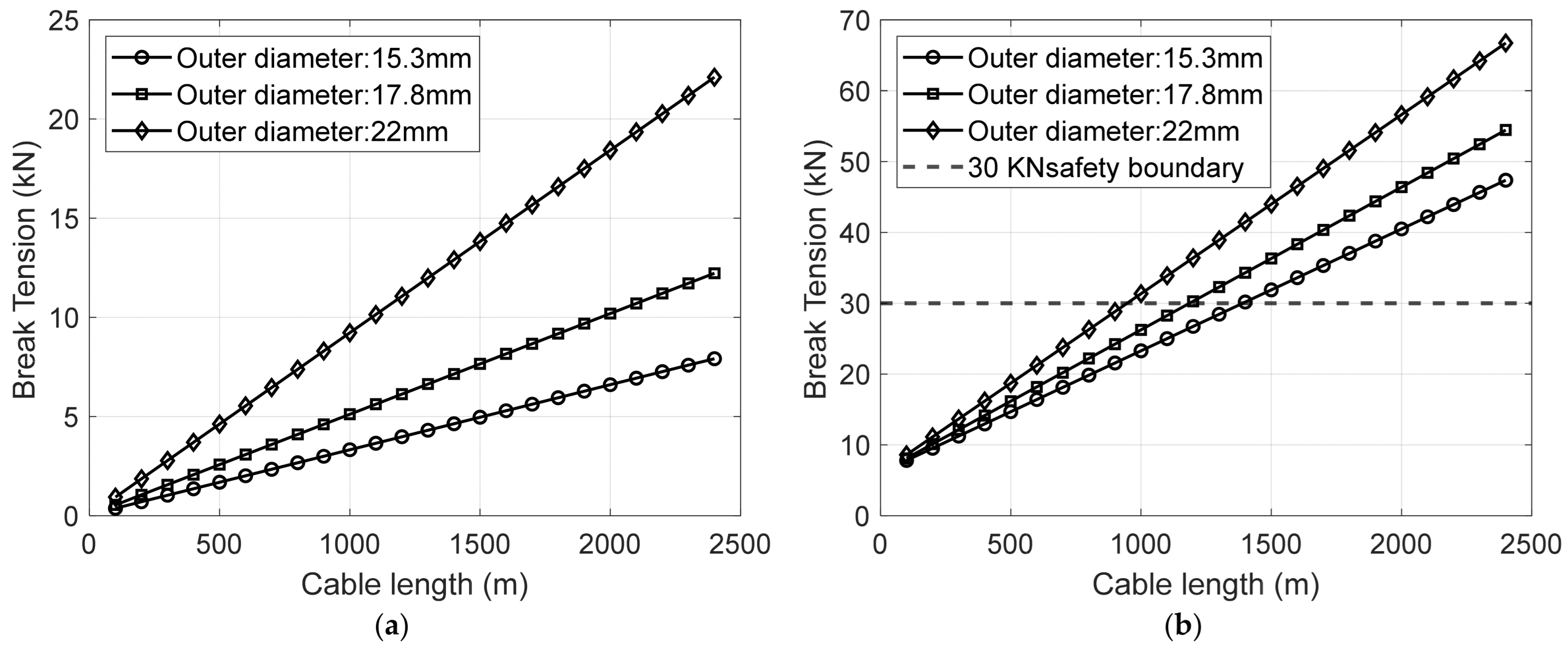
As shown in
Figure 4, the breaking tension variation characteristics of three main cables with different outer diameters at 2-knot and 18-knot speeds are compared and analyzed. A safety threshold of 30 kN is introduced as the constraint condition for the breaking tension of the line array.
Analysis indicates that the outer diameter of the main cable significantly influences breaking tension, exhibiting a positive correlation. Under identical speed and cable-laying length conditions, the 22 mm outer diameter main cable experiences the highest breaking tension, while the 15.3 mm cable exhibits the lowest. This disparity stems from the combined effects of fluid resistance characteristics and cable self-weight. Larger-diameter cables possess greater frontal area in seawater, significantly increasing tangential and normal resistance within the flow field, which in turn causes a sharp rise in top-end system tension.
At the low speed condition of 2 knots, breaking tension primarily stems from the underwater weight of the towing system itself. As the deployed cable length increases, tension rises linearly at a gradual rate. Even for the 22 mm outer diameter main cable, the maximum tension at a full length of 2400 m was only 22.11 kN, well within the 30 kN safety limit. This indicates that within the low-speed operating range, the towing system possesses ample structural safety margin for tension and is not the primary bottleneck for optimization.
However, conditions reverse at high speeds of 18 knots. Hydrodynamic drag increases proportionally to the square of speed, causing tension values to surge dramatically. Here, the dual effect of outer diameter parameters becomes pronounced. While the 22 mm main cable facilitates greater submersion depth, its larger frontal area significantly amplifies hydrodynamic drag, resulting in the steepest break tension curve.
22 mm main cable outer diameter: At a deployment length of just 95 m, breaking tension approaches the 30 kN safety threshold.
17.8 mm main cable outer diameter: Safe deployment length extends to approximately 1150 m.
15.3 mm main cable diameter: Experiences minimal resistance, enabling a safe deployment length of up to 1400 m.
In summary, tension characteristics at high speeds impose physical strength constraints on towed array systems. While larger main cable diameters improve submergence depth, they significantly narrow the operational window, meeting tension safety standards. This trade-off between submergence depth and tension reduces the maximum permissible cable deployment length.
3.3. Impact of Speed and Cable Length on Array Safety
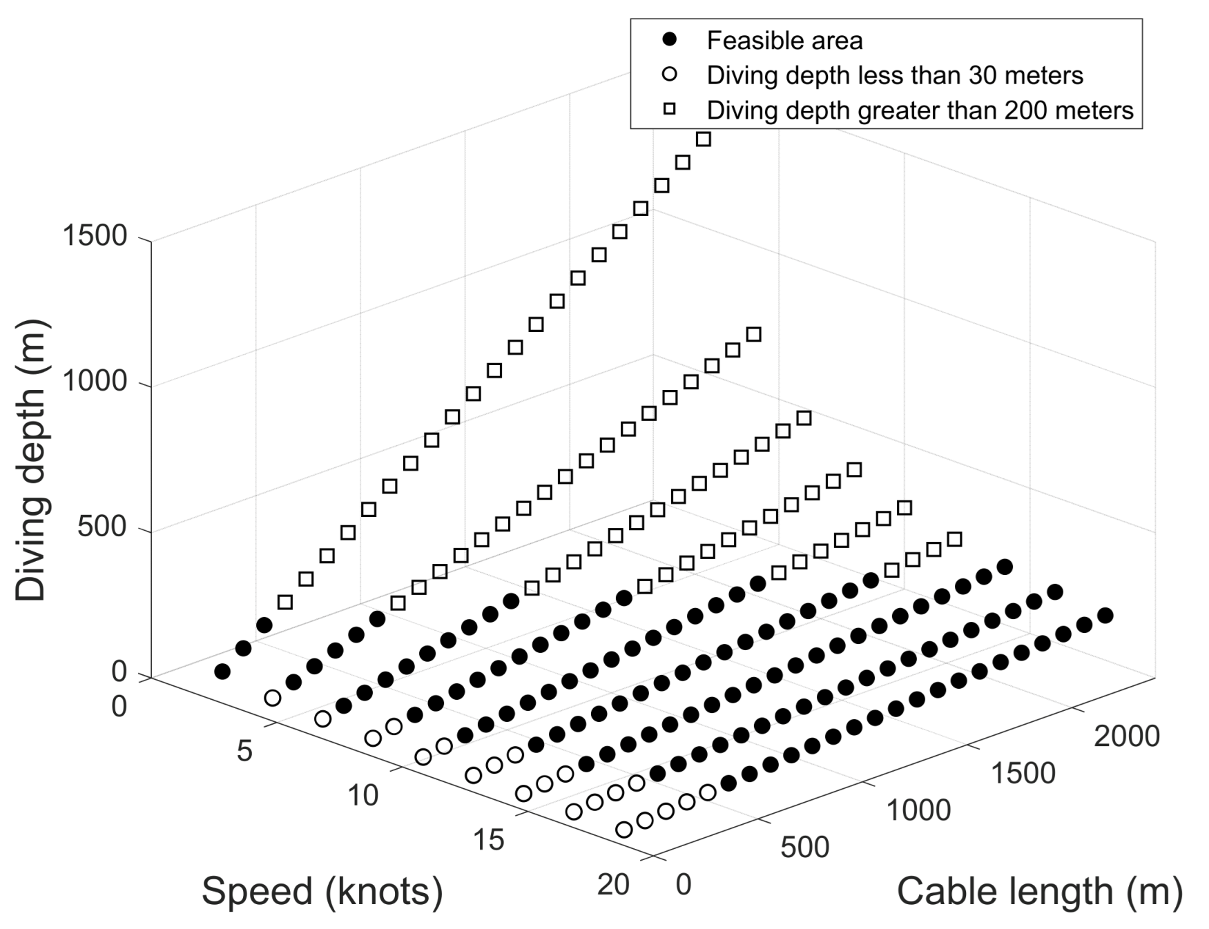
Using a 15.3 mm diameter main cable as the test subject, a dual-parameter variable experiment (“speed-cable length”) was conducted. At speeds ranging from 2 to 18 knots and cable lengths from 100 to 2400 m, the constraints on diving depth and breaking tension safety limits were analyzed. A total of 216 simulation data sets yielded the following results:
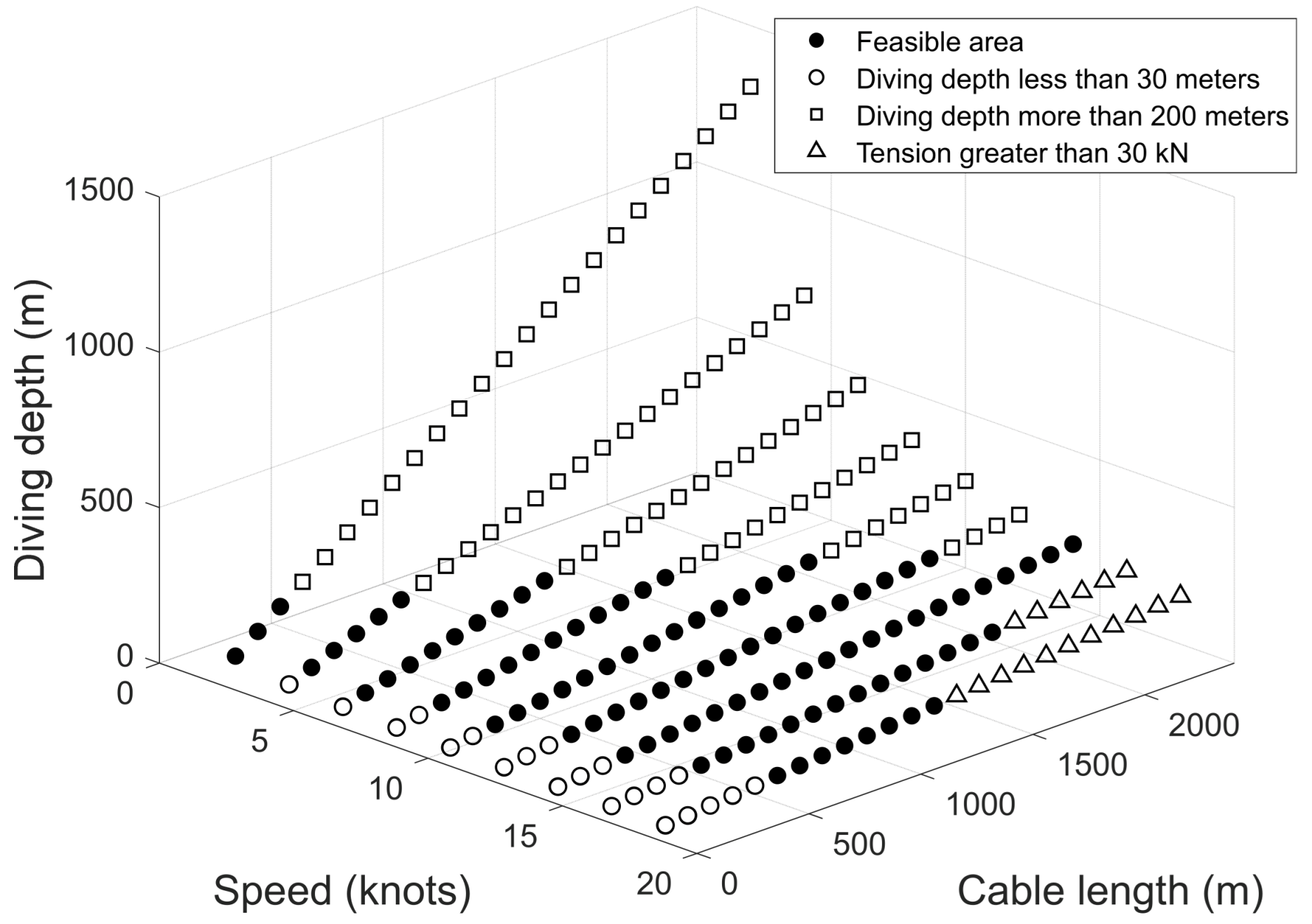
As shown in
Figure 5, when diving depth alone serves as the safety limit constraint, 120 feasible operating points exist, accounting for 55.6% of the total. Among these, 9.7% exhibit excessively shallow diving depth, while 34.7% show excessively deep diving depth. The results indicate that excessively deep diving depth represents the primary depth-related safety risk for towed line arrays, whereas excessively shallow diving depth has a relatively minor impact on safety limits.
In the depth-constrained scenario of towed array systems, the influence of cable payout length and vessel speed on diving depth fundamentally stems from the coupled effects of the cable’s force equilibrium state and motion posture in water. Cable length is the core parameter determining the vertical distribution and net weight force of the cable. The towed cable experiences two vertical forces in water: its own weight and buoyancy. As cable length increases, the cable’s volume proportionally expands, causing both weight and buoyancy to rise simultaneously. However, since the main cable’s density far exceeds that of water, the increase in its own weight far outweighs the buoyancy gain, ultimately manifesting as increased diving depth.
Ship speed is a key parameter affecting the horizontal forces on the cable. It influences diving depth by altering the cable’s “horizontal drag force” and “attitude angle.” As the towed array moves with the mother ship, the cable experiences horizontal drag resistance from the water flow. This resistance is proportional to the square of the ship speed, meaning even a slight increase in speed significantly amplifies the horizontal drag force. Cable tension can be decomposed into horizontal and vertical components: the horizontal component balances the water current drag resistance, while the vertical component balances the net weight of the cable.
As speed increases, the horizontal drag force grows, reducing the cable’s attitude angle and consequently diminishing the vertical component. If the vertical component fails to fully counterbalance the net gravitational force, the cable’s downward tendency is suppressed, resulting in reduced diving depth. Conversely, when speed decreases, the horizontal drag force diminishes, the attitude angle increases, the vertical component grows, and ultimately, the diving depth increases.
Cable length and speed do not independently affect diving depth but interact through the equilibrium relationship between net weight force and vertical component force. Specifically:
When the deployed cable length is excessively long and the ship’s speed is simultaneously too low, the reduced horizontal drag force, increased attitude angle, and amplified vertical component force can cause the diving depth to rapidly exceed specifications. This combination of operating conditions resulting in excessive diving depth accounts for 34.7% of cases. Increasing speed at this point boosts horizontal drag force, reduces the attitude angle, and lowers the vertical component force. This partially offsets the downward pull of net gravity, maintaining depth within safe limits.
When the cable length is too short, even at low speeds where net gravitational force is minimal and cable sag is limited, excessive depth is unlikely. However, at high speeds, further suppression of sag may cause the depth to become too shallow. This aligns with the 9.7% occurrence of shallow depth points in the figure, predominantly resulting from the “high speed-short cable” combination.
Figure 6 illustrates the variation in the safe operating envelope when incorporating breaking tension constraints. Considering the impact of breaking tension on the main cable reduces the number of viable operating points from 120 to 103, with 17 points (7.9%) exhibiting excessively high breaking tension.
As shown in
Figure 6, depth and tension exhibit a coupled constraint relationship. The feasible region under single-parameter constraints is further compressed by the synergistic effects of multiple parameters. During towing, the total tensile force on the main cable results from the vector sum of horizontal towing force and vertical net weight force. This implies that increases in either speed or cable length directly elevate total tensile force. When either parameter exceeds a certain threshold, the total tensile force may surpass permissible limits even if diving depth remains within safety ranges, creating operational points where depth is compliant but tensile force is excessive. From the parameter distribution, points with excessive tension are primarily concentrated in the “high speed-long cable” combination. High speed dramatically increases the horizontal towing force on the cable. Excessive cable length increases the vertical net weight force, and the combined total tension exceeds the tension limit.
This distribution pattern validates the “coupled constraint of tension and depth,” where the two parameter combinations—dominated by “horizontal force” and “vertical force” respectively—compress the original safe depth feasibility range. While increasing cable length facilitates greater diving depths during high-speed operations, this comes at the cost of sacrificing the safety margin of breaking tension. Consequently, under high-speed conditions, breaking tension replaces diving depth as the primary constraint, becoming the decisive factor limiting maximum cable deployment length.
3.4. Safe Maneuvering Envelope for Towed Cable Array
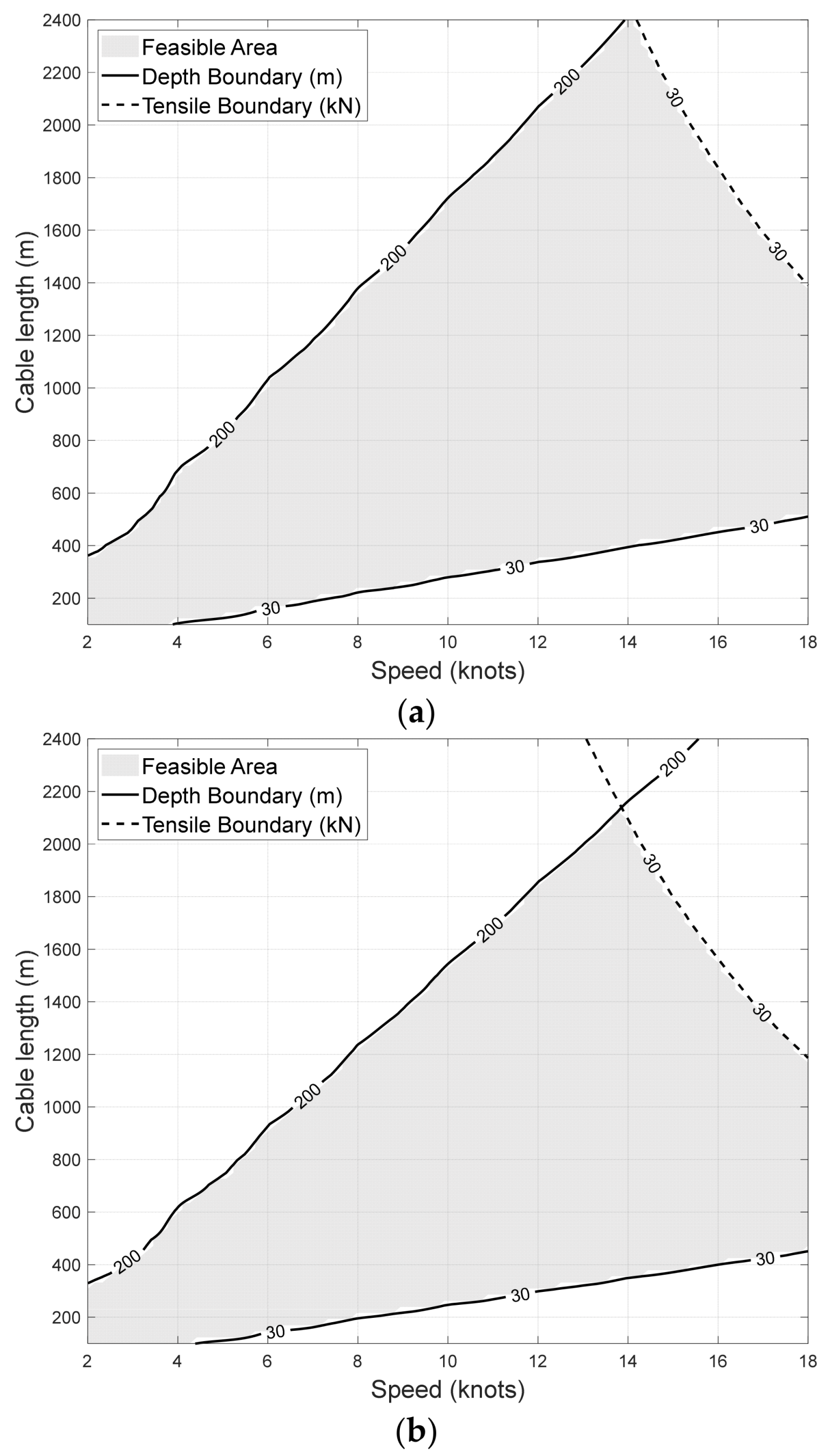
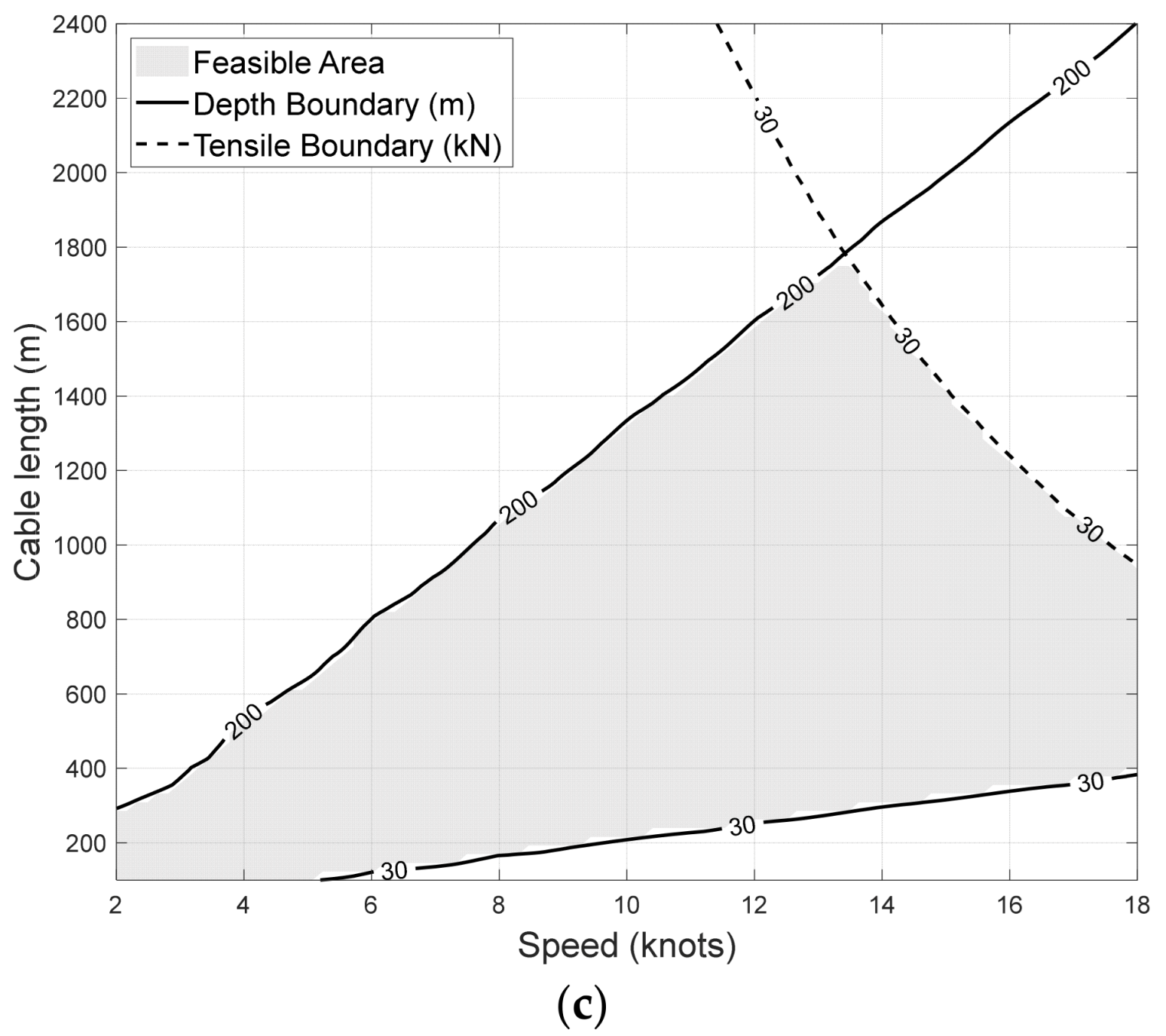
The safe operating limits for towed array systems are constrained by both diving depth and maximum winch pull force, creating a complex multi-parameter optimization problem. To accurately construct a continuous and smooth operational envelope from the finite discrete simulation cases, a high-resolution data mapping procedure was implemented. Specifically, the scattered simulation results for steady-state depth and terminal tension were interpolated onto a high-density 100 times 100 regular grid spanning the entire velocity-length parameter space. This process utilized Delaunay triangulation-based linear interpolation, which ensures localized accuracy while preventing the artificial overshoots typical of higher-order polynomial splines. Subsequently, robust iso-contour tracking algorithms were applied to this dense grid to precisely extract the nonlinear intersection boundaries corresponding to the safety thresholds. Based on this high-resolution projection of three-dimensional constraints onto a two-dimensional parameter space, the complete safe operating window for the towed array is constructed and visualized, as illustrated below:
By comprehensively integrating the aforementioned analytical results, a complete safe operation window for the dragline array was established. The figure indicates the 30-m and 200-m safety boundaries along with the 30 kN safety boundary. The gray area enclosed by these three safety boundary lines, combined with a ship speed of 2 knots and a cable deployment length of 2400 m, represents the feasible operational domain that simultaneously satisfies all safety requirements. The delineation of this area provides a clear parameter range for the system’s safe operation. Boundary feature analysis reveals the dominant mechanisms under different constraints. The lower boundary—the minimum diving depth line—defines the minimum cable deployment length required to prevent cables from approaching the water surface too closely, thereby avoiding interference from surface turbulence, ship wakes, and other disturbances while ensuring acoustic detection equipment operates at effective depths. This boundary monotonically increases with rising vessel speed. The left boundary, representing the maximum submergence depth line, defines the maximum cable deployment length considering structural strength to prevent damage to line array equipment, primarily applicable in low-speed zones. The right boundary, denoting the maximum breaking tension line, constitutes a hard constraint of physical strength. As the main cable outer diameter increases, this boundary exhibits a steeper slope and shifts downward, becoming the core bottleneck for high-speed deep-towing operations.
In
Figure 7, as the main cable outer diameter increases from 15.3 mm to 22 mm, the topology and coverage area of the safe operating window exhibit significant evolutionary characteristics, profoundly reflecting the interdependent relationship between cable gravity and fluid resistance under different operating conditions.
For the 15.3 mm outer diameter main cable, the operating window is dominated by fluid lift effects, exhibiting a “high starting point, long span” characteristic. Due to its lower mass per unit length, this configuration exhibits weaker resistance to lifting at high speeds. To meet minimum submersion depth requirements, increased cable deployment length is necessary, significantly shifting the initial deployment threshold to the right and encroaching on the low-cable-length operational space in the high-speed segment. However, its smaller frontal area results in relatively relaxed tension constraints, allowing safe tension maintenance over a longer deployment range.
For the 22 mm outer diameter main cable, the operational window is dominated by fluid drag effects, causing a reversal in behavior. The significantly increased self-weight effectively suppresses high-speed lift-off, substantially reducing the minimum safe cable deployment length and expanding the feasible range of submergence depths. However, its large wetted surface area causes fluid drag to surge dramatically, significantly lowering the tension safety margin. At the 18-knot maximum speed, the permissible maximum cable deployment length is severely constrained, with physical strength limitations becoming markedly tighter.
The 17.8 mm outer diameter main cable configuration demonstrates a dynamic equilibrium between these two mechanisms. Compared to the 15.3 mm design, its moderate self-weight gain significantly enhances position-holding capability at high speeds. This improvement results in a reduction in minimum safe cable length that exceeds the maximum length reduction caused by increased drag. This boundary evolution enables the design to maintain a relatively ample effective operating bandwidth within high-current zones. It provides more robust parameter adjustment margins while ensuring structural safety, demonstrating strong adaptability to operating conditions and operational robustness.
3.5. Case Study
To further verify the applicability of the proposed Safe Maneuvering Envelope model under practical restricted engineering conditions, this section introduces a real-world physical towed line array system from published literature for case validation. Referring to the study by Zhang et al., a three-section composite towing computational model consisting of a lead cable, a sensor array, and a tail rope is established. The core benchmark physical parameters of the system are presented in
Table 2 [
32].
Based on the practical engineering parameters presented in
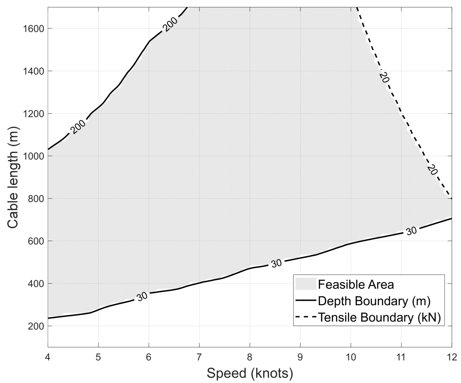
Table 2, the proposed multi-parameter coupled optimization method was utilized to calculate the response dataset of diving depth and breaking tension for the system at towing speeds ranging from 4 to 12 knots and cable payout lengths from 100 to 1700 m. The limiting constraints are set as a diving depth of 30 to 200 m and a breaking tension of 30 kN. Subsequently, its Safe Maneuvering Envelope within the operational space was solved and plotted, as shown in
Figure 8.
Combining
Figure 8 and
Table 3, it is evident that among the discrete operational conditions, both Case 1 and Case 2 fail to meet the depth constraints required for the line array’s operation. For Case 4, although its diving depth is adequate, the coupled effect of high towing speed and long cable payout induces immense hydrodynamic drag, causing the system tension to breach the 20 kN safety threshold and posing a risk of structural damage. In contrast, Case 3 falls accurately within the gray feasible domain of the envelope, achieving a balance between the target diving depth and the tension safety margin among various discrete operational combinations. These verification results indicate that even under the practical limitations where engineering equipment can only adopt discrete operational parameters, this method can intuitively and efficiently assist the system in mitigating risks. Consequently, the optimization model proposed above is fully demonstrated in practical engineering applications.
4. Discussion
Based on the theory of flexible cable dynamics, this study proposes a method for constructing a Safe Maneuvering Envelope that integrates both geometric and physical strength constraints, aiming to analyze the safe operational mechanisms of towed line arrays under multi-parameter coupling environments. By constructing a dynamic response model across the full parameter space, we found that the safety bottlenecks of the towing system are not static but exhibit a significant “interval drift” characteristic as operational conditions change. In the low-speed regime, the system is primarily gravity-dominated, and the cable assumes a typical catenary shape; here, the safety limit mainly manifests as the geometric risk of “excessive diving.” However, as vessel speed increases, hydrodynamic forces gradually become dominant, and safety limits evolve into a synergistic constraint of depth and tension. Particularly in the high-speed regime (>12 kn), physical strength constraints induced by fluid drag rapidly escalate into the decisive factor. This “tension truncation” effect is especially pronounced in thicker cable scenarios, significantly compressing the system’s effective operational window.
This shift in dominant mechanisms is further verified through the comparison of different cable diameter schemes. The analysis indicates that the selection of cable diameter is essentially a trade-off between the “gravity sinking benefit” and the “drag tension penalty.” However, this study further points out that this geometric advantage comes at the cost of a significant increase in tension. Due to the increased wet surface area, the frictional drag of the thicker cable rises sharply at high speeds, causing its Safe Maneuvering Envelope to be strictly limited by the tension boundary in the high-speed section. Conversely, the thinner cable offers the largest tension safety margin but suffers severely from lift effects at high speeds, resulting in insufficient diving depth. These mechanism shifts are not merely empirical trends but align closely with established theoretical frameworks of marine cable dynamics (such as the classical formulations by Ablow and Schechter). From a deeper theoretical perspective, the envelope limits represent a transition from a linear spatial boundary—governed strictly by the non-dimensional ratio of submerged weight to winch tension in a catenary state—to a highly nonlinear hydrodynamic boundary, strictly dictated by the coupling of quadratic fluid drag and axial elastic constraints.
From an engineering application perspective, the proposal of the Safe Maneuvering Envelope aims to establish a logical link between theoretical dynamic calculations and practical maneuvering decisions. Traditional towing operations often rely on the empirical judgment of operators, making it difficult to cope with multi-variable dynamic adjustments under complex sea conditions. The two-dimensional safe operating window constructed in this study attempts to translate abstract dynamic constraints—such as depth limits and breaking tension thresholds—into intuitive visual zones, providing a quantitative reference for decision-makers. This enables operators to more clearly identify whether the current operational state is within the safety envelope and to anticipate the potential risks of accelerating or deploying cables. For instance, when rapid maneuvering is required, the envelope chart can assist operators in planning an optimized path of “retrieving the cable before accelerating” to avoid high-tension risks associated with long cables at high speeds. This visualized decision support serves as a beneficial supplement to traditional experience-based operations and holds positive practical value for enhancing the reliability of ocean detection missions.
It is important to note that the safety limits defined in this study are currently based on idealized, steady-state towing conditions. In realistic, complex marine environments, however, factors such as wave-induced vessel heave and sharp maneuvers can cause severe cable oscillation—often referred to as a “whipping effect”—resulting in instantaneous tension spikes that may exceed the static safety boundaries established here. Additionally, complex underwater currents and variations in seawater density can compromise the stability of the array’s attitude. Therefore, the deterministic boundaries of the proposed SME should not be interpreted as absolute operational limits, but rather as critical thresholds enveloped by areas of uncertainty. To translate these theoretical limits into actionable maritime regulations and Safe Operating Procedures, the introduction of an ‘Uncertainty Buffer Zone’ is imperative. From a regulatory perspective, conservative safety margins must be applied to the theoretical SME—reserving specific percentages for the ultimate breaking tension and the allowable depth range. By highlighting these areas of uncertainty and delineating a recommended operational domain, the proposed Safe Maneuvering Envelope framework provides a direct quantitative basis for policymakers to establish risk-averse towing regulations, thereby ensuring the system possesses sufficient dynamic resilience against unforeseen marine disturbances.
Future research will focus on these time-varying dynamic processes by incorporating realistic environmental parameters into the model. We aim to refine the model boundaries using full-scale sea trial data to establish a more flexible “Dynamic Safe Maneuvering Envelope,” thereby providing more precise theoretical support for intelligent marine detection and autonomous control.